TECHNOLOGIES FOR DELIVERY OF PROTON AND ION BEAMS FOR RADIOTHERAPY HYWEL OWEN 1 , DAVID HOLDER School of Physics and Astronomy, Schuster Laboratory University of Manchester/Cockcroft Institute Manchester M13 9PL, United Kingdom [email protected],[email protected]JOSE ALONSO Accelerator and Fusion Research Division Lawrence Berkeley National Laboratory 1 Cyclotron Road, Berkeley CA 94720, USA [email protected]RANALD MACKAY Christie Medical Physics and Engineering The Christie NHS Foundation Trust Manchester United Kingdom [email protected]1. Introduction to External Beam Radiotherapy Soon after the discovery of x-rays in by R¨ ontgen in 1895, the therapeutic properties of radiation were being explored. Radiation was used initially as a treatment for a number of non-cancerous and cancerous conditions. In modern times radiotherapy has been used almost exclusively in the curative and palliative treatment of cancer, often in combination with surgery and chemotherapy. 1 Radiotherapy may be divided into two principal categories: 1 Preprint submitted to Int. J. Mod. Phys. A October 2, 2013 arXiv:1310.0237v1 [physics.acc-ph] 1 Oct 2013
Transcript
TECHNOLOGIES FOR DELIVERY OF PROTON
AND ION BEAMS FOR RADIOTHERAPY
HYWEL OWEN1, DAVID HOLDER
School of Physics and Astronomy, Schuster LaboratoryUniversity of Manchester/Cockcroft Institute
Soon after the discovery of x-rays in by Rontgen in 1895, the therapeuticproperties of radiation were being explored. Radiation was used initially asa treatment for a number of non-cancerous and cancerous conditions. Inmodern times radiotherapy has been used almost exclusively in the curativeand palliative treatment of cancer, often in combination with surgery andchemotherapy.1 Radiotherapy may be divided into two principal categories:
1
Preprint submitted to Int. J. Mod. Phys. A October 2, 2013
arX
iv:1
310.
0237
v1 [
phys
ics.
acc-
ph]
1 O
ct 2
013
• Brachytherapy - the use of sealed and unsealed radioactive sourcesplaced near to or within the tumour requiring treatment;2,3
• External beam therapy (originally termed teletherapy) - the use of anexternal beam of radiation, usually produced by a particle accelera-tor4,5, 6 but also by radioactive sources.7,8, 9, 10
Teletherapy beams are provided either directly or from a source of sec-ondary radiation; for example x-ray generation from electrons striking aBremsstrahlung target. Fast neutrons, or more exotic particles such as pions,are also possible. In addition there are treatment involving two steps, such asboron neutron-capture therapy (BNCT), in which epithermal neutrons areabsorbed by 10B nuclei which have chemically bound to tumour cells, givingrise to alpha particle emission and hence a very local radiation dose.
The amount of energy deposited as radiation passes through a given depthof tissue is referred to as the linear energy transfer (LET). X-rays and pro-tons are considered to be low LET radiations, while other hadronic particlebeams such as neutrons and carbon ions are considered to have high LET.The predominant type of external beam radiotherapy is x-ray therapy, wherea small (typically less than 2 metres) standing-wave or travelling-wave lin-ear accelerator (linac) accelerates electrons to an energy of around 10 MeVtypically. When incident upon a transmission target these electrons produceBremsstrahlung radiation. This photon beam can then be collimated andflattened to produce a uniform beam of defined field size. In the UK around130,000 treatments a year are presently delivered involving 2.5 million atten-dances, more than half of which are for breast and prostate treatment.11
Although the linacs used for x-ray therapy are both relatively compactand produced in large numbers, and therefore relatively inexpensive com-pared to proton and other ion accelerators, the resultant radiation dose de-livered by the photons within the patient is not ideal. Whilst photons give alow surface dose - providing valuable skin sparing - this dose rises rapidly to amaximum within the first ≈2.5 cm of tissue before falling with depth due toattenuation and the inverse-square law. A single beam direction will there-fore deliver lower dose at the depth of the tumour than it does to healthytissue upstream and will unnecessarily irradiate healthy tissue downstreamthe tumour. These inherent limitations may be partly overcome to give bet-ter conformation to the tumour of the delivered dose by:
• Bringing beams onto the target volume from a number of directions;
2
• Defining the transverse shape each beam using a multi-leaf collimator(MLC);
• Varying the intensity of each beam through the technique known asintensity-modulated radiation therapy (IMRT).
Through these means modern x-ray radiotherapy can provide good con-formation of the high-dose volume to the target, but inherent in the treat-ment is the irradiation of large amounts of healthy tissue with medium andlow doses. Good treatment planning seeks to optimise this tradeoff and tominimise dose to sensitive structures.12,13,14,15,16 There are presently around265 linacs in clinical use in the UK and a funded programme to dramaticallyexpand the use of IMRT.11 Three-dimensional computed tomography (CT)provides sufficient resolution of the electron density to x-rays17,18,19 giventhat the depth-dose curve for x-ray absorption is rather smooth. This issupported by magnetic resonance imaging (MRI) to improve targeting, par-ticularly in soft tissues. Computer-aided optimisation of the treatment doseis used with a number of irradiation fields to spare tissues and organs at riskthat are near to the tumour.12,20,13,21,5, 22, 23
2. Particle Therapy
In contrast to x-ray therapy, radiotherapy with charged hadronic speciessuch as protons feature a depth-dose curve that concentrates the dose aroundthe Bragg peak, a characteristic of the Bethe-Bloch energy loss for these par-ticles.24,25,26,27,28 The depth at which the peak occurs increases with particleenergy; for incident protons above 70 MeV an approximate rule of thumb isthat protons lose around 1 MeV per millimetre of water traversed, althoughthis reduces with increasing incident energy. The range of a 230 MeV pro-ton is roughly 33 cm in water, so that this energy is sufficient to be usedfor tumour treatment in a typical adult patient. For a given depth of theBragg peak, heavier particle species such as carbon ions require greater en-ergy; for example, to treat to a depth of 33 cm would require a C 6+ ionof 400 MeV/nucleon. Both accelerators and beam delivery systems to thepatient must cope with the significantly greater beam rigidity if carbon ionsare used (see later), leading to greater magnetic bending and focusing fieldsand thus larger accelerators.
With efficient ion sources and compact accelerators, protons are the mostaccessible of hadronic beams and deliver tangible benefits over photons when
3
traded-offs against accelerator size and cost.24 However, heavier ions havethe distinct advantages of greater radio-biological effectiveness (RBE) andsmaller lateral scattering; carbon ions in particular have been used for patienttreatment for this reason.29
The sharp peak in the hadron depth-dose curve means that accurate imag-ing and planning are very important; a 1 cm range error in x-ray radiotherapywill change the dose to the tumour or normal tissue by approximately 2 %along the beam path, whereas a 1 cm range error in hadron therapy will shiftthe distal edge of the dose distribution and may thereby give a much largerchange to the dose delivered at a particular location.
Whilst CT provides sufficient tissue density information for planning x-ray treatments, the conversion of Hounsfield numbers to tissue density isnot accurate enough to provide optimal proton planning.24 Hence there issignificant interest in improving existing imaging techniques with, for ex-ample, a number of researchers developing proton computed tomography(PCT)30,31,32,33 and positron emission tomography (PET)-based dose moni-toring, the latter utilising the 11C and 15O generated during proton or carbonirradiation.34
In order to provide PCT, particularly in adult patients, the proton energymust be larger than that required for treatment; protons exit the patient witha residual energy which is measured and - by comparison with the already-known entrance energy - used to determine the integral of the patient tissuedensity along the line between entrance and exit.35,32 Tomographic recon-struction from many such tracks is undertaken in the same manner to otherimaging techniques, but since the density determined here is proton-specificit may be translated directly into a required proton energy for treatment.This method may thereby reduce range error if the proton energy can bemeasured accurately enough.
As well as photons, protons and carbon ions, radiotherapy has also utilisedother particle species. Very high-energy electron therapy (VHEET) uses anelectron beam (of energy up to 250 MeV) directly rather than using it tocreate x-rays;36,37 at sufficiently large energies there is believed to be a ther-apeutic benefit compared to photons, but compact facilities require larger ac-celerating field gradients than are yet commercially available. Fast neutronswere used in clinical studies during the 1960s and 1970s but poor dose local-isation overshadowed the high-LET benefits.38,39,40,41 Finally, exotic speciessuch as pions and antiprotons are also candidates for radiation therapy. Thepotential advantage of these latter two species is the additional energy pro-
4
duced from the nuclear absorption of the stopped particles, adding to theenergy released at the Bragg peak depth; this is referred to as a star dose.42
The use of antiprotons has also been studied, particularly at the Antipro-ton Cell Experiment (ACE) at CERN;43 the proposed advantages are theRBE enhancement adjacent to the Bragg peak from the antiproton annihi-lation, and the possibility of using the pions generated for dose monitoring.Recent studies confirm such an RBE enhancement, but at present there isdisagreement about the acceptability of the longer-range halo dose.44,45,46
Held out as a great hope for treatment of glioblastoma, boron neutron-capture therapy (BNCT) is a combined technique in which epithermal neu-trons (from a suitable reactor or accelerator-based source) are shaped inenergy by a moderator assembly to optimise their spectrum to be absorbedby 10B nuclei bound chemically to (possibly dispersed) tumour cells, giv-ing rise to alpha particle emission and hence a (very) local radiation dose.47
The main challenges for BNCT use are the availability of a compact, high-flux neutron source, the subsequent shaping of the source spectrum to avoidneutron irradiation that can cause very substantial damage to tissue outsidethe tumour region and the development of suitable boron compounds thatcan penetrate the blood-brain barrier and bind to tumour cells.48,49 PresentBNCT facilities utilise either a neutron source derived via a graphite columnfrom a nuclear reactor, or moderate the fast, broad-spectrum neutron out-put from a thick lithium or beryllium target struck by protons with energiestypically between 2 and 30 MeV.50
3. History of Particle Therapy
Following Robert Wilson’s suggestion of using protons for radiation ther-apy,51 experimentation was started using the 184-inch synchrocyclotron atLawrence Berkeley Laboratory;52,53 the first patients were treated in 1952,but not with stopped beams.54 At that time diagnostic devices were notavailable to provide adequate tissue-density information to determine thecorrect beam energy for the protons to stop in the tumour; this level ofsophistication did not emerge until CT scanning became available in the1970s. The earliest treatments used plateau irradiation, in which the full en-ergy beam of up to 900 MeV was collimated and passed through the targetvolume. Incident beams were delivered to the patient at a variety of angles,overlapping the delivered fields to concentrate the dose at the desired loca-tion.55,56 Target volumes were small (for example at the pituitary gland)
5
and ablation studies for treatment of endocrine-related diseases (Cushingsacromegaly) were highly successful. Over 2000 patients were treated by thistechnique in Berkeley. Russian programmes at ITEP and at St. PetersburgNuclear Physics Institute/CRIRR were also quite successful.57,58,59,60 Fol-lowing experiments initiated at NIRS (Chiba) and at Tsukuba at the endof the 1970s,61,62 Japan has become one of the world’s largest users of bothproton and heavy ion therapy.63
Stopped-beam treatments with protons (i.e. utilising the concentratedenergy loss at the Bragg peak depth) were started at the Gustav Werner In-stitute in Uppsala (Sweden) and at the 160 MeV Harvard Cyclotron (USA)in the early 1970s,55,64,65 although stopped helium ions had been used a fewyears earlier.54 Heavier ions were pioneered at the Berkeley accelerators, the184-inch synchrocyclotron producing helium beams and the Bevalac gener-ating therapeutic beams from carbon to argon. Over 2000 patients weretreated with these heavier ions, with the majority of Bevalac patients (closeto 500) receiving treatments with neon ions.
The first dedicated hospital facility was developed at Loma Linda usinga Fermilab-designed 250 MeV synchrotron and opened in 1990.66,67,68,65 Asynchrotron was chosen as it was considered that a synchrotron could pro-vide the rapid energy variation and dose rate control required for accuratepatient treatment. Subsequently cyclotrons, synchrotrons and latterly othertechnologies were developed for proton therapy, initially at accelerator labo-ratories and then commercialised by a number of providers.65,64 The LomaLinda facility pioneered the delivery of a single source beam to more thanone treatment room, enabling multiple patient treatment, although not si-multaneously due to the time required to switch from one room to another.Loma Linda also demonstrated the clinical use of rotating gantry systemsthat deliver protons into a patient from a number of directions, which avoidsthe need to rotate the patient other than in the horizontal plane, whilstessentially still providing treatment beams from any angle.
Extensive trials with pion beams were conducted at Paul Scherrer Insti-tute (PSI), TRIUMF and LAMPF in the 1970s, of which the most creativebeam delivery concept was developed at PSI; called the Pion Concentrator(or Piotron),69 the production target was struck with 590 MeV protons with60 channels fanning out in a cone from the optimum production angle ofabout 60 ◦. These channels transported purified and energy-selected pionsand brought the beamlets to an image point of the target at the site of thepatient; a sufficient dose rate of pions could be achieved so that a daily frac-
6
tion could be delivered in a few minutes. Several thousand patients weretreated with pions at these facilities;70,71,72,73 clinical results were unsatisfac-tory, in part due to the relatively poor dose localisation from greater multiplescattering of the pions compared to the substantially heavier protons. Therehave been studies of more cost-effective pion sources, such as PIGMI.74
Heavy ions for therapy first became available in the early 1970s at thePrinceton-Pennsylvania Accelerator75,76 and at the Bevalac in Berkeley,77
with measurements of the stopping profile and biological effects being madequickly.78,79 Being more massive than protons, heavy ions such as carbon,oxygen, nitrogen and neon will scatter less and thereby provide a sharperedge to the imparted radiation field.80 In addition LET is significantly higherthan for protons. However, a significant proportion of the ions may undergonuclear reactions that produce lighter fragments that can travel beyond theprimary Bragg depth; this tail dose is significant when treating at depthsgreater than 20 cm. More recent facilities in Japan, Germany and Italy haveopted for carbon ions, mainly because of the less damaging plateau dose andRBE enhancement near the Bragg peak, but also because of the reducedfragmentation and more manageable accelerator size.
4. Particle Sources
At present, nearly all hospital or laboratory centres use either a cyclotronor synchrotron as a particle source of either protons or carbon ions,81,82,83
delivering treatment beams to either single treatment rooms or (more fre-quently) multiple treatment rooms; in the latter case a transfer line andswitching magnets are required to select which room receives beam. Bothcyclotrons and synchrotrons are mature technologies with well-establishedroutes for delivering maximum proton energies in the 200-350 MeV range oreven higher.84,85 At present, carbon ions at clinically useful energies are onlyprovided using synchrotrons, although several cyclotron- and linac-based de-velopments are underway.
Many alternative technologies are in active development; these includelinacs, hybrids of linacs with circular machines,86 new techniques involvinginduction acceleration (e.g. dielectric wall accelerators), laser-generated pro-ton beams,87,88 or novel forms of conventional accelerators such as fixed-fieldalternating gradient (FFAG) rings.89,90,91 Those technologies in or close toclinical implementation are described below, whilst some others of interestare discussed in Section 7.
7
4.1. Normal-Conducting Cyclotrons and Synchrocyclotrons
The normal-conducting cyclotron was the first circular (and thereforecyclic) accelerator to be used, following its invention by Ernest Lawrence inthe 1930s.92,93,94 There are a number of variants, which include techniques tokeep the driving radio frequency acceleration in synchronism with the orbitperiod.95,96,97 Synchronism is achieved either by modifying the pole shapesto make the orbits isochronous, or by varying (in the synchrocyclotron) theRF frequency during an acceleration pulse. Virtually all hospital-based ther-apy cyclotrons utilise the first approach and at present deliver a maximumproton energy of 235 MeV, but several commercial vendors have proposed orare constructing synchrocyclotrons. Higher energies have been achieved inresearch machines such as the 590 MeV PSI cyclotron,98 but cyclotrons of thisenergy have not yet been commissioned outside of accelerator laboratories.
To allow for depth scanning of the tumour, some method must be em-ployed to vary the proton beam distal (maximum) depth, since the outputenergy from a cyclotron is to all intents fixed. To achieve this variation inincident proton energy, the beam from the cyclotron is passed through anadjustable thickness of some material, typically two back-to-back wedges ofcarbon. The mean energy loss is accompanied by an increase in energy spreadand beam emittance due to scattering, so the output beam must be cleanedin an energy-selection system prior to the final beam delivery system. En-ergy selection is achieved with a combination of dipole magnets, collimatorsand extensive shielding to select the energy and emittance of the beam thatcan be transported through the gantry to the patient. Typically cyclotronscan deliver sufficient beam intensity so that despite the beam loss from theenergy selection process (by as much as a factor of one hundred or more forthe lowest energies), they provide a dose rate that is competitive with otheraccelerator types. It is also worth noting that in typical cyclotron designs theoutput spot is basically circular, which simplifies the beam coupling to thefinal beam delivery system, for example to a downstream rotating gantry.
4.2. Superconducting Cyclotrons and Synchrocyclotrons
The higher fields (above about 3 T) which are available from supercon-ducting magnets allow higher extraction energies at a particular orbit ra-dius;99,100,101,102,103 this allows cyclotrons to be made smaller for a givenextraction energy but with the penalty of the greater capital cost of the mag-net and operating cost of the cryosystem.84,104 Reliability is not necessarilyworse with a low-temperature rather than a room-temperature magnet, as in
8
practice reliability is often determined by other points of failure. However,maintenance work on the accelerator will usually include a significant timeoverhead from warm-up and cool-down of cryogenically-cooled components.
Several commercial vendors are now either developing or offering super-conducting cyclotrons;103 Mevion utilise NbSn3 superconducting magnet coilsthat allow the cyclotron to be small enough to be gantry mounted whilstmaintaining a maximum proton energy of around 250 MeV. Varian-ACCELuse NbTi to have a larger, lower-field and therefore simpler magnet to obtain250 MeV protons at extraction,105 whilst IBA also use NbTi in their 230-250 MeV S2C2 cyclotron.104 Superconducting magnets are often less thanhalf the weight of their normal-conducting equivalent.25 There is a researchand commercial push to develop cyclotrons with higher extraction energies,but as yet no commercial solution has been installed to our knowledge.
4.3. Radiofrequency Linacs and Cyclinacs
Proton linacs for radiotherapy have been proposed, using either a con-ventional pre-injector or using a low-energy cyclotron as the proton source(so-called cyclinacs). Accelerating structure developments have been madetowards the goal of having sufficient accelerating gradient for them to be usedin a hospital context, particularly at S-band (3 GHz) frequency; two Italiancollaborations - TERA106,107,108 and TOP-IMPLART109 - have separatelydeveloped 3 GHz structures,110 whilst other groups have studied upgrades ofexisting cyclotrons.111 The frequency mismatch between the cyclotron andlinac can result in significant beam loss in the first cells of the linac, but thehigher current available at low energy compensates for this. This techniquehas also been pursued for carbon-ion therapy112 with structure developmentunderway.113,114 Low-energy sections for proposed facilities have been con-structed in Italy and clinical facilities are either planned or proposed hereand elsewhere. The TERA TULIP design proposes combining the accelerat-ing structures and rotating gantry to provide a single-room solution.115 Thesame structure development has also been recently proposed by AdvancedOncotherapy to provide a linac-based proton therapy centre,116 although nocentres are yet operating using this scheme.
4.4. Synchrotrons
Synchrotrons are a well-established technology in proton therapy andthere have been numerous slow-cycling (up to a few hertz) examples usedclinically.66,67,65,117,118,119,120,121,122,123 At present, synchrotrons are the only
9
accelerator technology used to provide carbon ion beams. All current de-signs follow the original approach by GSI and implemented at Heidelberg,122
which uses: an ECR ion source, a radio-frequency quadrupole and drift-tubelinac, and finally a synchrotron to accelerate carbon ions up to 400 MeV pernucleon.124,125,126 Energy variation of the proton or carbon beam distal (max-imum) energy is accomplished by extracting the beam at different times inthe acceleration cycle. Extraction is commonly achieved using either a third-order resonance or RF-knockout scheme and a feedback system is employedto ensure that the extracted dose can be controlled to provide both good dosestability and beam intensity that is programmable in time. Furthermore, ex-traction can be gated to synchronise the dose with the patient’s breathing, inorder to minimise the effect of organ motion. In comparison with isochronouscyclotrons, where particles are continuously injected and accelerated, in syn-chrotrons (and similarly in synchrocyclotrons) the injection window is short,so the number of particles available at treatment energies is substantiallylower. Nonetheless, dose rates are still adequate and in a synchrotron theavailable particle flux at each extraction energy is essentially constant; this isin contrast to cyclotrons, where the the extracted beam intensity is reducedby up to three orders of magnitude by the scatterers used to reduce the meanparticle energy.
4.5. Rapid-Cycling Synchrotrons
Brookhaven National Laboratory (BNL) in conjunction with a commer-cial company (BEST)127 have spearheaded the idea of a rapid-cycling syn-chrotron for either proton or carbon-ion therapy, although other groups havealso initiated designs.128 BNL propose that a maximum cycling frequency of30 Hz allows the use of simpler magnets and resonant power supplies and inprinciple a pulse-by-pulse energy variation at the cycling frequency is pos-sible by timing the firing of the extraction kicker during the accelerationphase.129,130 Slow extraction is not possible and intensity feedback is bothrequired and difficult; intensity control must be done either by trimmingduring acceleration, or by exquisitely fine control over the injected current.
5. Facility Layout Options
A single accelerator can provide a particle beam to a single treatmentroom or to multiple treatment rooms; some rooms may then have gantries totranslate the horizontal beam entering the treatment room into the vertical
10
plane, with the patient either stationary with the gantry rotating aroundthem (isocentric) or with some combination of patient and gantry motion.The rationale for gantries, and their design issues, are discussed below. Thecombination of a rotating gantry with a patient table that rotates in thehorizontal plane allows the particle beam to enter the patient from any angle,in contrast to treatment with a fixed beam orientation. A third option is tomount the accelerator on the gantry, which is only possible if the acceleratoris small and light enough that the resulting gantry is of reasonable size; ofcourse in this scenario the accelerator can only support one treatment room.
In most proton and carbon-ion systems today the particle source is notmounted on the gantry, but instead is located in a separate, static location.The advantage of having several treatment rooms supplied by a single ac-celerator is that patients can be prepared for treatment in parallel prior toirradiation, thus making optimal use of the available accelerator time. Thegantry beam-optics system must couple to the source, and beam switching isideally fast so that the beam is ready for initiation of treatment within a shorttime (typically less than one minute) from the operator’s request. The dis-advantages of a single accelerator/multi-room arrangement are the reductionin flexibility and the complication of parallel patient scheduling, althoughthe optimisation of throughput planning is becoming more advanced. MonteCarlo modelling studies suggest three to four treatment rooms per acceler-ator provides optimal utilisation of all resources.131,132,133 In a multi-room,single-accelerator facility there is the risk of the accelerator source being thesingle point of failure for all treatment rooms, which must be taken intoaccount. Reliability (measured as the fraction of time available over that de-manded) of the accelerator systems of at least 98 % is typically required.134
Such facilities may be upgraded by modifying or replacing the acceleratorwhilst leaving the treatment rooms as they were; this modification has beenperformed at the PSI proton therapy centre where a dedicated cyclotron wasadded to an existing treatment room suite.135
Whilst the shielding requirements in all proton or carbon-ion facilitiesare naturally significant, particular attention must be paid in cyclotron-basedfacilities to the relatively larger amount of activation arising from the energy-selection system. Conversely, coupling cyclotron and linac beam optics togantry optics is relatively simpler due to the circular beam spot. This is incontrast to synchrotrons where the spot may be significantly asymmetrical;this requires rather special measures to match the accelerator and gantrybeam optics.136
11
If the particle source can be made small enough the option exists tomount it directly on the treatment gantry. Since the accelerator is directlymounted on the gantry, the beam optics are much simpler but the gantry as awhole may not be smaller or lighter, depending on the source used (typicallya compact cyclotron,137,138 but potentially a dielectric wall accelerator orlaser-based acceleration scheme, see below). The issues of parallel treatmentand scheduling are greatly simplified or eliminated and if there are a numberof treatment rooms each with its own gantry and source then there is nobeam-derived single point of failure. Beam clean-up and elimination of theparasitic neutron dose will however be more complex as they must be doneclose to the patient. Whilst some studies indicate that this could be manage-able, the issue is still a the subject of research.139 Presently, only compactsuperconducting synchrocyclotrons can deliver 250 MeV protons whilst atthe same time being small enough for the gantry and treatment room to bepracticable.
6. Beam Delivery and Field Formation
It is of course not enough to merely bring a hadron beam into a treatmentroom; its distribution transversely and longitudinally must be capable of be-ing conformed to the tumour volume in (x, y, z) according to a predeterminedtreatment plan. Prior to the operation of the Loma Linda facility, treatmentswere carried out using both fixed beamlines and fixed patient orientation.
Flexibility in the entry orientation of the beam is important, and whilststatic horizontal delivery is still preferred for some fields (such as oculartreatments) the capacity to provide an arbitrary entry angle, via a gantry,is highly favoured by the medical community.140 The use of gantries andthe related issues of field shaping and dose conformation and how they areachieved using passive or active methods are discussed below.
6.1. The Use of Gantries
As well as the requirement to spread the dose throughout the volume ofthe tumour, it is of course desirable to direct treatment beams with the leastpossible impact on organs or other tissues that are either in close proximityto the treatment volume or which lie between the treatment volume andthe patient’s external surface. To achieve this goal, it is necessary to eitherrotate the patient or rotate the beam line that is delivering the particlesto the patient. Although it is acceptable to rotate or translate a supine
12
patient in the horizontal plane, full six-dimensional patient motion is notpossible.140 This is primarily due to the undesirable organ motion relativeto the external body reference points used to align the treatment beam;thus horizontal rotation is acceptable but not other axes. Rotation mayalso be difficult for the patient, or interfere with other medical proceduressuch as anaesthesia. Some treatments are suitable for use with fixed anglebeam (which may be horizontal, vertical or something in between), with thepatient either supine, prone or sitting up; a notable example is the treatmentof ocular tumours where the patient is seated and the incident particle beamfixed and horizontal. However, to provide maximum flexibility the conceptof the rotating delivery beam line (gantry) has been developed, mimickingthe situation in x-ray radiotherapy where the gantry rotates 360 ◦ around apatient lying on a couch, with the couch’s default position along the axis ofgantry rotation. If the patient couch is allowed to rotate in the horizontalplane, a more compact treatment room is possible as the gantry is onlyrequired to rotate 180 ◦ (from vertically-down to vertically-up).
There are several reasons to keep the patient supine during radiotherapytreatment:
• To more easily reproduce the patient position used for pre-treatmentimaging such as CT that has been used for treatment planning;
• To more easily reproduce the patient position through several weeks ofdaily treatment;
• To maximise the flexibility in possible beam directions to avoid normaltissue and therefore to target the tumour most effectively.
In external beam radiotherapy by far the most common method is for thepatient to lie on a treatment couch, imitating the position used for CT scan-ning. When accompanied with sensible immobilisation devices, this ensuresorgans are in similar position during both treatment planning and treatment,to give a reproducible set up. To maximise the number of possible treatmentangles the couch can have up to five degrees of freedom, with tilts of thecouch limited to less than 5 ◦ for patient comfort.
6.2. Gantry Design
Conventionally, the term gantry is used to refer to a particle beam trans-port line that is designed to rotate around an axis; a gantry consists of a
13
mechanical support structure, drive mechanism, magnets, vacuum vesselsand beam diagnostics, along with other secondary technical infrastructure.The de-facto standard gantry design that has emerged is the isocentric ap-proach, wherein the patient is kept essentially still in a prone position withthe centre of rotation of the gantry passing in the horizontal plane throughthe patient and the incident beam rotated in the vertical plane around thepatient. A number of dipoles are used to transport the beam from the par-ticle source to the treatment room which it enters along this axis. Furtherdipoles on the gantry are used to create an offset between the beam and thegantry rotation axis and finally turn the beam toward the patient who ispositioned at the isocentre. Quadrupoles are used to provide beam focusingboth in the beam transport prior to, and within, the gantry. The isocentricapproach is shown schematically in Fig. 1.
Accelerator plane
(horizontal)
Gantry plane rotation
Gantry plane
(rotating)
Isocentre
Transfer line
Accelerator sourceCoupling point
Figure 1: A schematic illustration of a particle therapy installation incorporating an isocen-tric particle therapy gantry. The gantry plane rotates around an axis that is horizontaland passes through the isocentre within the patient.
The components between the final bending magnet and the exit windowto the patient are sometimes referred to as the treatment nozzle. As wellas beam position and dose monitors it may include deflection magnets toscan the spot transversely, or alternatively beam scatterers and collimatorsto spread and shape the proton dose across a chosen field size; these field
14
sizes may now be as large as 30 × 40 cm. The need for a treatment nozzlewill always require a distance of several metres between the last bendingmagnet of a gantry and the patient. To obtain a full 4π coverage of thepatient, the gantry must rotate at least 180 ◦ in conjunction with a patienttable that rotates 360 ◦ in the horizontal plane. To minimise patient rotation(which introduces time delay and may result in unacceptably large patientmisalignment) many gantry designs utilise the full 360 ◦ of rotation aroundthe patient.
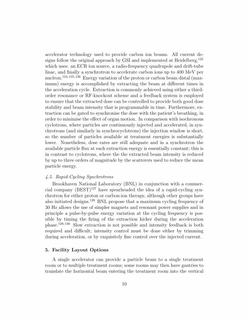
Isocentric gantry designs typically incorporate either two or three dipolesas illustrated in Fig. 2 (but may incorporate more126,141) and are designedto minimise the total mass of the gantry magnets whilst also minimising theouter radius and length of the entire rotating structure. Despite this, gantriesstill involve a large mass of magnet steel and a mechanical structure that ismany metres in both length and radius that rotates around the patient; mostof this assembly is typically disguised behind a false wall and therefore notvisible to the patient in the treatment room. Gantry-mounted sources suchas compact cyclotrons do not require the same number of beam steeringelements, since the particles from the cyclotron may be directed straight atthe patient; however there is then less space to incorporate beam cleaningand scanning elements.
Alternative approaches to the isocentric concept have been proposed toreduce the mass of moving steel. The most notable of these is the so-called“Riesenrad” (or ferris wheel) gantry, wherein a smaller number of deflectingmagnets lie on the gantry rotation axis and the patient displaced from thataxis; if the gantry and patient are rotated (but the patient kept supine)the patient will receive the dose from different angles.142,143 The Riesenradgantry is shown schematically in Fig. 3. Such gantries have less moving steeland are therefore lighter, but have more complex patient-handling issuescompared to isocentric gantry installations; the principal of these is thatpatient entry and egress are more time-consuming, which may be an issueduring emergencies.
A hybrid scheme (often referred to as an eccentric gantry) has been im-plemented at PSI (at Gantry 1), in which both the patient and the beamline magnets move around the rotation axis, thus minimising the overall di-ameter of the gantry.144,145 Unlike the Riesenrad gantry, which requires alarger shielded room, the compact eccentric gantry design reduces the sweptvolume to a minimum.
Most gantries in commercial proton therapy systems are isocentric and
15
Figure 2: Schematic illustration of isocentric 2- and 3-dipole gantry designs. The numberof quadrupoles required may be different to that shown. In both cases shown, spot scanningat the patient is obtained by using fast scanning magnets placed downstream of the finaldipole. As the energy of the protons is varied the gantry magnetic field strengths must bescaled to match the proton beam rigidity.
their size is dictated by their use of normal-conducting dipole magnets, whosemaximum field on the beam axis is restricted to around ≈1.8 T. Given thatthe beam rigidity of protons at 250 MeV is 2.43 Tm, a 1.8 T field implies abending radius of 1.35 m; this bending radius, along with the space neededfor the beam-spreading system to cover the treatment field, sets the overallsize of proton gantries, which are typically 5 to 6 metres in radius and havemasses between 100 and 200 tons.
For carbon ions the gantry must be significantly larger. The only currentexample of a carbon gantry is situated at the Heidelberg Ion Beam TherapyCentre (HIT), and is shown in Fig. 4.122 Here the maximum carbon ionenergy used for treatment is 425 MeV/u, corresponding to a beam rigidityof 6.57 Tm and a bending radius of 3.65 m. The use of normal-conductingdipole technology produces a gantry ≈19 m in length and nearly ≈15 m indiameter and with an overall mass of 600 tonnes (of which 135 tonnes is in
16
Gantry Rotation
Figure 3: Schematic illustration of Riesenrad gantry.
the magnets). Despite the very large rotating mass, the positional accuracyof the isocentre is maintained to ≈1 mm, similar to that achieved in a protongantry.
Another important factor in the gantry design is the method chosen tospread the energy of the delivered particles to cover the depth range of thetreatment volume. The beam energy can be chosen to position the Braggpeak at the distal edge of the tumour; range modulators in the treatmentnozzle are then employed to create a spread-out Bragg peak (SOBP) to matchthe tumour depth profile. Alternatively, if the dose is being delivered in aseries of depth slices the energy of the particles from the source is varied.In this latter case, the gantry magnet fields could in principle be kept fixed,as long as there is sufficient aperture to allow the required range of energiesto be transported (for example in an FFAG gantries with a large energyacceptance, discussed later), but typically in practice the gantry magnet fieldstrengths are varied to match the changing beam rigidity. The use of variablegantry magnet fields does not usually limit the rate at which treatment mayprogress from one depth layer to another in the treatment volume, as it isusually faster than the rate at which the energy may be varied at the source(e.g. the energy selection system of a cyclotron); typically a range step of5 mm may be achieved in ≈100 ms using a degrader, e.g. a pair of carbonwedges moving against each to give a varying thickness that is uniform acrossthe incident proton beam.
17
Figure 4: The Heidelberg carbon-ion gantry, presently the only operating gantry for carbonion treatment. (courtesy Prof. Thomas Haberer/Heidelberg Ion Beam Therapy Centre)
6.3. Scattering Methods
The mechanism employed to distribute the dose throughout the tumourhas a significant impact on the gantry design. Coverage of the tumour bythe beam in most of today’s installations is achieved using a passive beam-spreading technique. Passive scattering typically uses two scattering layers,in which the first (primary) scatterer spreads the beam out laterally and asecond, about half the distance between first scatterer and patient, has acomplex variation of thickness with distance from beam axis to provide adose that is uniform in intensity across the treatment field width.146,65
With a double-scattering design, lateral conformation to the tumour canbe achieved using either multi-leaf collimation (MLC), analogous to that usedin x-ray radiotherapy systems, or by manufacturing a custom collimator for
18
each individual patient treatment. However, the use of such collimation inthe treatment nozzle can produce an additional neutron dose for the patient.An alternative approach to scattering is to use a set of so-called wobblermagnets that paint the beam in a series of concentric circles, along withcollimators to establish the lateral field shape.65,147
Longitudinal conformation is achieved using the well-established tech-nique of utilising a range modulator and compensator,148 the latter beingmanufactured specifically for each patient treatment. These are typicallymanufactured from a polymer, the modulator being a spinning, wedgedwheel, generating a SOBP covering the tumour longitudinally; an exam-ple of this is shown in Fig. 5. The compensator is a fixed-energy degraderconformed in thickness laterally across the tumour to have the distal edge ofthe SOBP follow the distal edge of the tumour. This arrangement does notprovide optimal conformation to more complex target volumes, since the con-stant depth range delivered may be larger than the tumour in some locations.To achieve three-dimensional conformation, a range-stacking procedure mustbe used; the treatment volume is divided into a series of depth slices, eachwith a given outline determined by the MLC settings. By treating each depthslice sequentially, an irregular treatment volume can be covered with higherprecision.
6.4. Spot Scanning
The alternative to the scattering or wobbler magnet approaches is spotscanning. This is a key emerging technology that is being developed for fu-ture proton and carbon therapy systems, as well as for retrofitting to existingfacilities. In most designs a pencil beam of a given energy and a few millime-tres transverse size is directed to a given set of coordinates in the treatmentvolume by a pair of fast-scanning deflection magnets, which cause the beamspot to dwell on that voxel until the prescribed dose is delivered there. Thescanning magnets then move the beam to the next set of coordinates andso forth until the beam has been painted over the full area of the treatmentvolume at that desired depth. The beam energy is then changed to treat thenext layer of the treatment volume, gradually building up the layers untilthe entire volume is treated. A treatment plan based on patient imaging isused to optimise the dose over the entire treatment volume, taking accountof the dose both upstream and downstream of the Bragg peak delivered by aparticular spot. Depending upon the largest intended treatment volume thescanning beam may need to address transverse fields up to 400 × 400 mm,
19
Figure 5: Compensator (top) and range modulator (bottom) used at Clatterbridge Hos-pital to provide longitudinal conformation of the 62 MeV protons delivered from theircyclotron to the depth range of the tumour. The modulator wheel is 190 mm in diameter.(courtesy Prof. Andrzej Kacperek/Clatterbridge Hospital)
although most facilities presently specify not more than 200 × 200 mm. Inany case the treatment of very wide areas may be achieved by using thetechnique of field patching, in which the patient table is moved relative tothe isocentre.
The combination of pencil-beam spot scanning with a variable beam anglefrom a gantry enables the technique of intensity-modulated particle therapy(IMPT), in which several treatment fields (gantry angles) with inhomoge-neous doses are combined to maximise the dose at the tumour and to min-imise the dose to healthy tissue. IMPT involves active beam delivery devicesand thus requires similarly fast and accurate dosimetry; typically only afew milliseconds can be budgeted to deliver the dose to a voxel if the totaltreatment time is to be kept to a few minutes. Other advantages of spotscanning are the elimination of patient-specific hardware - rendering patientsetup faster and less costly - and a reduction in beam loss and hence neutrongeneration in the vicinity of the patient. In most current treatment nozzledesigns, the pair of fast-scanning deflection magnets are mounted after thefinal dipole, as shown in Fig. 6.
An important figure of merit in pencil-beam spot scanning is the source-
20
Figure 6: A schematic illustration of an idealised isocentric 3-dipole gantry which incor-porates spot scanning magnets downstream of the final dipole. Whilst the aperture inthe final dipole may be made relatively small, there may be a significant difference in fieldsize (and correspondingly higher dose per unit area) at the patient surface compared tothat at the isocentre due to the finite source-to-axis distance (SAD).
to-axis distance (SAD), which is the distance from the isocentre to the ap-parent source of the particle beam If there are no beam focusing elementsbetween the scanning magnets and the isocentre, the effective source locationis the point at which changes to the angle of the beam are made, i.e. thelocation of the scanning magnets. Since the beam trajectories diverge fromthe source, the area intercepted at the patient’s skin will be smaller than thearea at the isocentre depth, and thus a higher dose will be delivered to theskin. Making the SAD as large as possible will therefore give the best degreeof skin sparing. There are two methods by which the SAD may be made ei-ther very large, or even infinite. The first is to have two pairs of fast-scanningdeflection magnets mounted after the final dipole (one pair for each plane)which could produce a parallel beam translation at the patient surface; thiseither requires a large distance from the final dipole to the patient to developthe lateral spot offset - which demands a larger gantry radius - or very tech-nically demanding scanning magnets. Whilst this double-magnet approachhas been proposed - for example in combination with an FFAG gantry149 -it has not yet been implemented anywhere.
The second approach is to have either one or both of the fast-scanningdeflection magnets upstream of the final dipole (one for each plane); thisscheme is shown schematically in Fig. 7. The beam optics can then be de-signed such that the beam leaving the final dipole is translated parallel tothe zero-deflection axis as the scanning magnets alter the entrance angleof the beam into the dipole, thereby giving an effectively infinite SAD. In
21
this upstream scheme the gantry radius does not need to be increased toinclude scanning; however the good field region (and therefore the magnetpole width and the pole gap) of the final dipole must be increased to allow forthe transverse beam displacement required to produce the chosen treatmentfield size, which adds significantly to its weight. In principle other beamoptical arrangements may also be used to achieve the point-to-parallel focus-ing. The first example of a parallel scanning gantry was PSI Gantry 2,150
implemented in 1996; the final dipole is shown in Fig. 8, whilst the treatmentroom is shown in Fig. 9.
Figure 7: A schematic illustration of an isocentric three dipole gantry which incorporatesspot scanning magnets upstream of the final (90 ◦) dipole. With appropriate beam opticsand entrance and exit edge angles, the betatron phase advance between the scanning mag-nets and the isocentre may be made approximately 90 ◦, resulting in an effectively infiniteSAD. The disadvantage is that the aperture within the final dipole must be sufficient forthe intended field size, necessitating a larger good field region and hence greater mass andexcitation current requirements.
The first proton treatment gantry was constructed at the Loma Linda pro-ton treatment centre and utilised a now-unusual “corkscrew” optics scheme,the design providing a full 360 ◦ rotation of the beam axis around the pa-tient.151,152 Most commercial gantry designs presently offer 360 ◦ coverageand, if present, place the scanning magnets after the last dipole. As scan-ning systems are usually retrofits to gantries originally fitted with passivescattering nozzles, there is an inherently finite SAD. However, retrofitting ascanning nozzle downstream of the final dipole does not necessitate signifi-cant changes to the gantry beam optics.
A variety of optical schemes exist for downstream scanning, but for up-stream scanning the “Pavlovic” design is the foremost.153 In the Pavlovicthree-dipole design the positioning of both scanning magnets upstream ofthe final 90 ◦ dipole minimises the gantry radius whilst still providing an in-
22
Figure 8: The gantry mechanism and final dipole of Gantry 2 at the Paul Scherrer Insti-tute. The upstream design enables parallel scanning, which thereby simplifies treatmentplanning and gives an infinite SAD which assists in skin sparing but necessitates a ratherlarge 45-tonne final dipole to give sufficient aperture to deliver the desired treatment fieldsize. (courtesy Prof. Tony Lomax/PSI)
finite SAD; the number of quadrupoles needed to match the beam from thecoupling point at the end of the beam transport to the isocentre has beenminimised to be as few as six, as shown in Fig. 10. As well as providingparallel scanning the gantry optics design also manage the dependence ofinput beam size with gantry angle, which is a more significant issue for theusually non-symmetric beams from synchrotrons, but is solvable.117
Besides the minimisation of gantry length and radius, another method ofreducing the footprint of a treatment room is to utilise rotations of less than360 ◦; using 180 ◦ of rotation from vertically-downward to vertically-upward(on one side of the patient), nearly half the building footprint may be saved.It is then of course necessary to rotate the patient table for some fields; typicalisocentric gantry and table rotation speeds are similar at ≈1 revolution perminute, so “180 ◦” gantries may not significantly add to treatment time.However an added problem is introduced, which is to maintain accuratepatient position registration after the table rotation. Nevertheless, the useof restricted gantry rotation can significantly increase the patient treatmentcapacity on an existing clinical site, or on the restricted space available in
23
Figure 9: The Gantry 2 treatment room at the Paul Scherrer Institute. The rotating gantryis concealed behind a sliding false wall; sufficient distance must be provided between theend of the treatment nozzle and the patient to allow safe rotation. However, the distancefrom the end of the nozzle to the patient surface should also be minimised as far aspracticable to limit scattering in the intervening air. (courtesy Prof. Tony Lomax/PSI)
the urban population centres often attractive for siting hospital facilities. Afinal method which has been considered is to use obliquely-exiting beamsfrom the gantry, which allows for a smaller radius but restricts the range oftreatment field directions for supine patients.154
As mentioned earlier, it is also possible to directly mount the accelera-tor source onto the gantry, as may be done with high-field superconductingsynchrocyclotrons; several examples are presently under construction andcommissioning by Mevion in the USA. Gantry sizes are similar to those fornormal-conducting gantries fed by external sources and are typically pro-posed as either single-room or scalable clinical solutions, noting that single-room solutions are also offered which do not mount the source on the gantry.Another scheme is TULIP, a hybrid method in which a small (e.g. 60 MeV)cyclotron injects protons into a combined linac and gantry. Again, this is pro-posed as a single-room solution, but has not yet been implemented althoughthe accelerating structures have been developed as part of the related cyclinac
24
Figure 10: Layout of the “Pavlovic” gantry with a minimised number of quadrupoles (Q1to Q6) and three dipoles (BM45 and BM90). Sh and Sv are the horizontal and vertical(respectively) scanning magnets. (courtesy Prof. Marius Pavlovic/STU)
approach described earlier.115
7. Future Developments
7.1. Particle Sources
The conventional accelerator source technology utilised in current protonand carbon therapy is now rather mature; a good overview of those technol-ogy trends has been performed by Amaldi et al.83 Here, we discuss threeparticular technology developments with recent significant results.
7.1.1. Dielectric Wall Accelerators
Dielectric wall accelerators (DWA) for proton therapy are a developmentfrom technology originally developed for high-intensity Blumlein-type lin-ear induction accelerators to conduct flash radiography. Recent work usesimprovements in solid state switching technology to achieve direct, cavity-less acceleration with potential gradients as high as 100 MV/m.155,156,157 Ifachieved in a complete accelerator, such a gradient would allow a completeacceleration system to 250 MeV to be only several metres in length, poten-tially allowing it to be mounted on a gantry. Sample structures have beendemonstrated and a commercial company (CPAC) is offering a solution, witha prototype system proposed to be ready for clinical testing around 2015.
As mentioned earlier, one of the disadvantages of the classical cyclotronis the loss of synchronism with a fixed-frequency accelerating cavity as theaccelerating protons become more relativistic; the synchrocyclotron alleviatesthis problem by varying the RF frequency during bunch acceleration, with theconcomitant penalty of reduced intensity since only one bunch may be presentin the synchrocyclotron per RF frequency sweep. However, the relativisticlimit has limited the practically-achievable proton energies in either methodto ≈250 MeV.
FFAGs are an adaptation of the cyclotron with significant differences thatenable higher energies to be achieved.158,159 In both the cyclotron and theFFAG the magnet field is fixed in time but may vary both azimuthally andradially; the difference is that in the FFAG there is an alternating gradi-ent in successive dipoles such that the circulating particles see strong ratherthan weak focusing. The FFAG is thus akin to a strong focusing synchrotron(albeit without varying magnetic fields) and without separated-function mag-nets (i.e. separate dipoles and quadrupoles) in its layout.
The so-called scaling FFAG is similar to the cyclotron in having a betatrontune that is approximately constant during acceleration, achieved by varyingthe magnetic field nonlinearly with radius. The term “scaling” refers to thefact that the orbit shape scales with energy to maintain a constant betatrontune, so that the bunches may be kept away from damaging resonances (sim-ilar to the procedure adopted in most particle accelerator designs). However,like the cyclotron, the orbit radius varies greatly with energy and requireslarge-aperture magnets to accommodate a significant energy range, say fromthe 10s of MeV at injection to the extraction energy for treatment. Theadvent of fast swept-frequency accelerating cavities around a decade ago en-abled the first demonstration of proton FFAGs that could accelerate particlesin less than 1 ms; energies up to 150 MeV have now been demonstrated inJapan as part of the development towards future high-power proton acceler-ators,160 and applied at lower energy to the efficient generation of neutronsfor boron-neutron capture therapy.161
The non-scaling FFAG uses strong non-linear magnets to allow accelera-tion over a large energy range whilst retaining small-aperture magnets, andhas recently been demonstrated experimentally for electrons.162 Althoughthe magnets may be made smaller, the lack of orbit scaling with energy in-herently gives rise to the crossing of resonances during acceleration; it has
26
been demonstrated that this may be successfully carried out if magnet toler-ances are sufficiently well controlled, but a demonstration of the non-scalingprinciple with protons has yet to be carried out.
Two detailed design studies have been carried out to examine the use ofFFAGs for medical therapy, although others have also been performed.163,164
The first - RACCAM - was a design study for a multi-room treatment centrebased on a 180 MeV normal-conducting scaling FFAG.165 Energy variationin 250 keV steps (one step per second) is planned at five possible extrac-tion points, each potentially equipped with a patient gantry. However, thescanning speed is envisaged to be significantly better than that obtainablewith present-day synchrotrons. The second design study - PAMELA89 - pro-posed a two-ring non-scaling FFAG delivering both protons up to 250 MeVand carbon ions up to 400 MeV/u; a novel superconducting magnet tripletdesign was developed during the course of the study to allow nonlinear cor-rection of the magnetic lattice.166,167 The proposed advantage of PAMELAis the possibility of having variable energy pulses delivered at rates as highas 1 kHz; the difficulty resides in the need for rather complex superconduct-ing magnets and a very fast pulsed extraction system to produce the rapidenergy variation. Whilst there is potential commercial interest in FFAGs,there are at present no planned clinical centres that utilise them.
7.1.3. Laser Proton Acceleration
Protons and other ions may be accelerated using laser pulses in severalways; recent reviews have been given by Daido et al.,168 Norreys169 and Mac-chi et al.170 One recent advance has been the demonstration of so-calledtarget normal sheath acceleration (TNSA), whereby protons are acceleratedfrom the rear of a thin target illuminated by a strong laser pulse due to theelectron pressure within the target.171 Acceleration of protons and ions hasbeen demonstrated up to 10s of MeV with reasonable beam quality and en-ergy spread;168,172,173 however, whilst scaling to clinically-relevant energiesup to 250 MeV has been modelled there has not yet been demonstration tothose energies. A number of research groups are engaged in achieving thisgoal, and are considering how to deliver the pulse repetition rates requiredfor clinical application174 and to utilise the resulting protons.175 One av-enue is the use of radiation-pressure (“light sail”) acceleration,176 in whichthe incident photons themselves impart momentum to the accelerated ions.Whilst the use of laser technology is very promising, it is likely that it will bea few years before clinical experiments are carried out and there are no com-
27
mercial companies with plans to offer laser-accelerated protons for clinicaluse. One possible advantage of laser-based acceleration, like other compactproton sources, is the ability to mount the entire particle source onto a deliv-ery gantry. Efficient collection and focusing of these laser-derived particlesrequires a compact delivery system, based on either conventional magnets(either quadrupolar or solenoidal)177,178 or on Gabor lenses.179,180
7.2. Gantries
Similar to accelerator sources, delivery gantries have seen a great dealof development; in contrast though, gantry design has evolved towards oneof two canonical design approaches, either an isocentric gantry deliveringexternally-generated protons, or a gantry-mounted source delivering protonsdirect to the patient. Here, we discuss two approaches for making isocentricgantries more compact.
7.2.1. Superconducting Magnets
All three of the driving forces in gantry development, namely:
• Reducing their size and cost;
• Increasing the beam energy for the same size;
• Utilising ions heavier than protons;
require increased magnetic field strength (both for bending and focusing)integrated over the beam path. Of course, the gantry size is a significant costdriver of the whole treatment facility; a gantry treatment room is comparablein size or larger than most accelerator sources. Also, gantries for carbon iontherapy require larger magnets and in order to have a wider adoption ofcarbon-ion therapy it will be necessary to reduce the size and mass of themagnets. One method to achieve this is to adopt superconducting technology.
The advantages of superconducting magnets are that they can supporta much larger magnetic field than a normal-conducting magnet and becausethere are almost no resistive losses in the magnet circuit they cost less topower. Widely used in particle accelerators used for research for many years,they consist of either iron-cored or core-less magnets incorporating supercon-ducting coils which are typically cooled to less than 4 K using liquid helium;the use of high-temperature superconductors in this application has not yetbeen widely demonstrated.
28
Several groups - some with commercial involvement - have proposed core-less curved superconducting dipoles which produce fields up to 3.3 T ormore.181 Core-less superconducting dipole magnets have been prototyped tosome extent, but suitable magnetic field distribution and quality have notbeen demonstrated experimentally for all the magnet types required in a prac-tical gantry. Superconducting gantry designs are underway at ETOILE182
and NIRS;183 for example, the 3.3 T field proposed for ETOILE signifi-cantly reduces the dipole bend radius for 425 MeV/u carbon ions to around2 m, resulting in gantry dimensions (13.5 m long by 4 m radius) and mass(210 tonnes) which are comparable to normal-conducting gantries for pro-tons. An example of a superconducting gantry design for NIRS is shown inFig. 11 and Fig. 12. The NIRS design envisages their synchrotron producingcarbon ions between 430 MeV/u and 56 MeV/u in 200 steps, correspondingto a 1 mm to 2 mm range in water.184 Ridge filters are then used to producea mini-SOBP of between 1 to 3 mm. Similarly, the superconducting magnetswill change their field to match the beam energy within 200 ms. The resultsof tests of the prototype magnets and cryostats are promising.185
Although there are savings in the electrical power circuits that supply su-perconducting magnets coils when compared to normal conducting coils, su-perconducting magnets are more problematic to use than normal-conductingones as they must be cooled to a few kelvin. There is also the higher capi-tal cost associated with the magnets themselves and for their cooling system.The use of conventional liquid helium-filled cryostats is probably not possibleas liquid movement during rotation would lead to potential quenching, andso the approaches described above typically plan to use cryocoolers. Theseare cryogen-free heat pumps186 and so allow rotation of a magnet on a gantry,but they typically have a more limited capacity than cryogenic-liquid coolingsystems. The NIRS design envisages a pre-cooling procedure using liquid ni-trogen to reduce the temperature to ≈70 K, prior to the use of cryocoolers tofurther cool the magnets to 4 K. This will reduce the total time to get fromroom temperature to 4 K from about a month to six or seven days. A furthercomplication is that superconducting magnets are prone to quenching whennew (and until a period of training has been undertaken) and also when re-quired to change field rapidly. Tests at NIRS have shown that quenches canbe recovered from immediately; although realistically it may take up to twohours. It is not yet clear how quenching would be managed if it happenedpart-way through a treatment fraction. That being said, significant progresshas been made in Japan toward the realisation of a superconducting gantry
29
and it is likely that one will be operational soon.
7.2.2. FFAG Gantries
An alternative approach to conventional beam optics using supercon-ducting magnets is the use of fixed-field, alternating-gradient (FFAG) opticswhich in principle give very large energy acceptance with a small magnetaperture. FFAGs gantries make use of combined-function dipole magnetswith large focusing gradients that alternate in sign along the beam path.The large gradients, and the use of non-scaling beam optics design, min-imise the dipole-generated beam dispersion and thereby restrict the aperturerequired for a given energy range; energy scanning may then be carried outwithout varying the magnetic field of the gantry magnets. Thus some designspropose the use of permanent magnets to reduce the weight. FFAG gantriesmay also utilise superconducting or conventional normal-conducting magnettechnology, and a number of optical and technological solutions have beenproposed.187,164,149 It is proposed in particular that FFAG gantries for car-bon ion transport may be significantly smaller and lighter than other designs.An example layout of a superconducting FFAG gantry is shown in Fig. 13. Intreatment situations where the energy range that is required is larger than isavailable from the FFAG gantry optics, it is proposed to use a small numberof magnetic field settings to cover the depth range. Although a number ofinnovations have been proposed, including the provision of parallel scanningmentioned previously, an FFAG gantry has not yet been demonstrated.
8. Summary
Following a long period of experimentation before becoming fully ac-cepted, proton and other light ion beam therapies are now well-establishedclinical techniques. Whilst IMRT may give excellent dose conformation tothe tumour, protons provide the possibility of significantly reducing the doseto surrounding tissues and organs at risk. For the treatment of particulartypes of cancer this advantage outweighs the additional technology costs,particularly in paediatric treatments where the induction of secondary tu-mours or other side-effects can have particularly deleterious impacts on thepatient in later life.
In recent years - and particularly in the last decade - proton treatmenttechnology has advanced greatly, and the advent of scanned beams and IMPT
30
have significantly improved the capability of proton treatment. Mature tech-nology solutions are now available in the marketplace, but there remain op-portunities for improvement, either to further improve clinical capability orto reduce cost; both of these aims are important to realise the full potentialof proton and ion therapy. There is already a well-established pattern in thisfield, in which accelerator technology research from state-funded research(e.g. at national laboratories) has been successfully transferred and devel-oped to clinical practice by commercial organisations. Ion beam therapy hasbenefitted from the forward-looking nature of many companies in the fieldand from the investment they have been brought to create new products.
A number of novel accelerator technologies are being developed that as-pire to provide greater capability or reduced cost, but will have yet to showtheir advantages in comparison to existing offerings. At the accelerator sourceend, we note the steadily increasing use of superconducting technology forproton acceleration, which has aimed to reduce cost and size, enable mobilesources, or enable higher energies to be achieved. We also note dielectric wallaccelerators and non-scaling FFAGs as being disruptive technologies: theypromise significantly improved capabilities (DWAs offering much reduced sizeand ns-FFAGs promising more rapidly variable energy), but neither have yetbeen demonstrated in a clinical setting.
Carbon-ion therapy has become the de-facto standard for (non-proton)ion therapy and makes inherently greater demands on the technology com-pared to protons. As a result, it has pushed the development of higher-gradient acceleration and higher magnetic fields for beam delivery. Severalgroups have been involved in developing superconducting magnets suitablefor gantries and we believe this is a key technology for the near future.The strong focusing and compact magnet arrangements available in FFAGgantries could also offer potential benefits for scanning and to obtain smallersize, but given the more complex beam optics it will be necessary to constructa prototype.
It is not only carbon ions that may benefit from the use of higher fields orother methods to achieve smaller gantry sizes than the present successful butconservative designs. In proton therapy, there is a desire to reduce the gantrysize to enable a larger number of treatment rooms on a given site or to enablehigher energies to be transported, e.g. to enable the use of proton computedtomography. Given the typically urban location of treatment centres thisdesire will persist. We note here the trend towards opting for reduced gantryangle range (≈ 180 ◦ instead of ≈ 360 ◦) for which there is a tradeoff between
31
capital cost and throughput. Throughput remains a key indirect cost driverand the possible reliability and throughput advantages of gantry-mountedsources has only begun to be addressed by the initial example developed byMevion.
In conclusion, we believe that despite the great advances in ion therapytechnology in the last few years, there remain significant opportunities. Inthe near-term we believe superconducting technology will play an increas-ingly important role, particularly in beam gantries. Further on, new com-pact accelerator sources - possibly including laser-based acceleration - offerthe ability to provide gantry-mounted solutions if sufficient gradient can beachieved; these could potentially offer throughput or cost advantages, buthave to compete against the established mature solutions based on conven-tional accelerator technology.
Acknowledgments
The authors would like in particular to thank Dr. Yoshiyuki Iwata andProf. Marius Pavlovic for useful discussions and information.
This work was supported in part by the United Kingdom Science andTechnology Facilities Council.
References
[1] Juliette Thariat, Jean-Michel Hannoun-Levi, Arthur Sun Myint,Te Vuong, and Jean-Pierre Gerard. Past, present, and future of radio-therapy for the benefit of patients. Nature Reviews: Clinical Oncology,10(1):52–60, 2013.
[2] I Norderhaug, Olav Dahl, Per Høisæter, Reino Heikkila, OlbjørnKleppd, Dag Rune Olsene, Ivar S Kristiansen, Hakon Wæhre, andTruls E Bjerklund Johansen. Brachytherapy for prostate cancer: Asystematic review of clinical and cost effectiveness. European Urology,44(1):40–46, July 2003.
[3] Georgios Koukourakis, Nikolaos Kelekis, Vassilios Armonis, and Vas-silios Kouloulias. Brachytherapy for prostate cancer: A systematicreview. Advances in Urology, 2009(6):1–11, 2009.
[4] D Fruy and R Shersby-Harvie. A traveling-wave linear accelerator for4 MeV electrons. Nature, 162(4126):859–861, 1948.
32
[5] Thomas Bortfeld. IMRT: a review and preview. Physics in Medicineand Biology, 51(13):R363–R379, June 2006.
[6] D. Greene and P.C Williams. Linear Accelerators for Radiation Ther-apy. CRC Press, 2nd edition, 1997.
[7] H Johns, L Bates, and T Watson. 1000 curie cobalt units for radiationtherapy. I. The Saskatchewan cobalt 60 unit. The British Journal ofRadiology, 25(294):296–302, 1952.
[8] Jake Van Dyk and Jerry J Battista. Cobalt-60: An old modality, arenewed challenge. Current Oncology, 3:8–17, 1996.
[9] R Ravichandran. Has the time come for doing away with cobalt-60 teletherapy for cancer treatments. Journal of Medical Physics,34(2):63–65, 2009.
[10] J. R. Williams and D. I. Thwaites. Radiotherapy Physics: In Practice.Oxford University Press, USA, 2nd edition, 2000.
[11] National Radiotherapy Implementation Group (NIRG). Radiotherapyservices in England 2012. Technical report, UK Department of Health,2012.
[12] S Webb. The Physics of Conformal Radiotherapy. Institute of PhysicsPublishing/Taylor & Francis, 1997.
[13] S Webb. Intensity-Modulated Radiation Therapy. Institute of PhysicsPublishing/Taylor & Francis, 2001.
[14] P Mayles, A Nahum, and J C Rosenwald. Handbook of RadiotherapyPhysics: Theory and Practice. Taylor & Francis, 2007.
[15] Ann Barratt, Jane Dobbs, Stephen Morris, and Tom Roques. PracticalRadiotherapy Planning. Hodder Arnold, 4th edition, 2009.
[16] Peter Hoskin, editor. Radiotherapy in Practice: External Beam Ther-apy. Oxford University Press, 2012.
[17] Vincent S Khoo, David P Dearnaley, David J Finnigan, Anwar Pad-hani, Steven F Tanner, and Martin O Leach. Magnetic resonance imag-ing (MRI): considerations and applications in radiotherapy treatmentplanning. Radiotherapy and Oncology, 42(1):1–15, 1997.
33
[18] V S Khoo and D L Joon. New developments in MRI for target volumedelineation in radiotherapy. The British Journal of Radiology, 79:S2–S15, 2006.
[19] L A Dawson and C Menard. Imaging in radiation oncology: A per-spective. The Oncologist, 15(4):338–349, April 2010.
[20] C Nutting, D P Dearnaley, and S Webb. Intensity modulated radiationtherapy: a clinical review. The British Journal of Radiology, 73:459,2000.
[21] A Garden, W H Morrison, D I Rosenthal, K Chao, and K K Ang.Target coverage for head and neck cancers treated with IMRT: reviewof clinical experiences. Seminars in Radiation Oncology, 14(2):103–109,2004.
[22] Liv Veldeman, Indira Madani, Frank Hulstaert, Gert De Meerleer,Marc Mareel, and Wilfried De Neve. Evidence behind use of intensity-modulated radiotherapy: a systematic review of comparative clinicalstudies. The Lancet Oncology, 9(4):367–375, April 2008.
[23] J Staffurth. A review of the clinical evidence for intensity-modulatedradiotherapy. Clinical Oncology, 22(8):643–657, October 2010.
[24] Harald Paganetti and Thomas Bortfeld. Proton beam radiotherapy -the state of the art. New Technologies in Radiation Oncology (MedicalRadiology Series), 2005.
[25] Ute Linz, editor. Ion Beam Therapy. Springer, 2012.
[26] K Peach, P Wilson, and B Jones. Accelerator science in medicalphysics. The British Journal of Radiology, 84(Special Issue 1):S4–S10,February 2012.
[27] Marco Durante and Jay Loeffler. Charged particles in radiation oncol-ogy. Nature Reviews: Clinical Oncology, 7(1):37–43, 2010.
[28] Jay Loeffler and Marco Durante. Charged particle therapy - optimiza-tion, challenges and future directions. Nature Reviews: Clinical Oncol-ogy, 10(7):411–424, 2013.
34
[29] William T. Chu. Heavy ion radiotherapy: Yesterday, today and to-morrow. In International Symposium on Heavy-Ion Radiotherapy andAdvanced Technology, 2011.
[30] K. M. Hanson et al. Computed tomography using proton energy loss.Phys. Med. Biol., 26(6):965, 1981.
[31] U. Schneider and E. Pedroni. Multiple coulomb scattering and spatialresolution in proton radiography. Med. Phys., 21(11):1657, 1994.
[32] R. W. Schulte et al. Density resolution of proton computed tomography.Med. Phys., 32(4):1035, 2005.
[33] C. Talamonti et al. Proton radiography for clinical applications. Nucl.Instrum. Methods Phys. Res., A, 612:571, 2010.
[34] K. Parodi et al. Patient study of in vivo verification of beam deliveryand range, using positron emission tomography and computed tomog-raphy imaging after proton therapy. Int. J. Radiat. Oncol. Biol. Phys.,68(3):920–934, 2007.
[35] R. W. Schulte et al. Conceptual design of a proton computed tomogra-phy system for applications in proton radiation therapy. IEEE Transac.Nucl. Sci., 51(3):866, 2004.
[36] R. Wideroe. High-energy electron therapy and the two-component the-ory of radiation. Acta Radiologica, 4(4):257, 1966.
[37] C Yeboah and G A Sandison. Optimised treatment planning forprostate cancer comparing IMPT, VHEET and 15 MV IMXT. Phys.Med. Biol., 47:2247, 2002.
[38] Rowland L. Morgan. Fast neutron therapy. AIP Conf. Proc., 9:562,1972.
[39] M. Catterall, I. Sutherland, and D. K. Bewley. First results of a ran-domized clinical trial of fast neutrons compared with x or gamma raysin treatment of advanced tumours of the head and neck. Report to theMedical Research Council. Br. Med. J., 2:653, 1975.
[40] M. H. Maor et al. Fast neutron therapy for locally advanced head andneck tumors. Int. J. Rad. Oncol. Biol. Phys., 7:155, 1981.
35
[41] A Wambersie, F Richard, and N Breteau. Development of fast neu-tron therapy worldwide: Radiobiological, clinical and technical aspects.Acta Oncol., 33:261, 1994.
[42] G. C. Li et al. Pion dose calculations suitable for treatment planning.Phys. Med. Biol., 19(4):436, 1974.
[43] Bradly G Wouters et al. The biological effectiveness of antiproton ir-radiation. Radiotherapy and Oncology, 81(3):233–242, December 2006.
[44] J N Kavanagh, F J Currell, D J Timson, K I Savage, D J Richard,S J McMahon, O Hartley, G A P Cirrone, F Romano, K M Prise,N Bassler, M H Holzscheiter, and G Schettino. Antiproton inducedDNA damage: proton-like in flight, carbon-ion like near rest. Nature:Scientific Reports, 3:1770, 2013.
[45] Michael Goitein and Dan Jones. Radiation oncology: A physicist’s-eyeview. Physics Today, 61(12):55, 2008.
[46] Harald Paganetti, Michael Goitein, and Katia Parodi. Spread-out an-tiproton beams deliver poor physical dose distributions for radiationtherapy. Radiotherapy and Oncology, 95(1):79–86, April 2010.
[47] H. J. Taylor and M. Goldhaber. Detection of nuclear disintegration ina photographic emulsion. Nature, 135:341, 1935.
[48] S. Green. Developments in accelerator based boron neutron capturetherapy. Radiat. Phys. Chem., 51:561, 1998.
[49] R. F. Barth et al. Boron neutron capture therapy of cancer: Currentstatus and future prospects. Clin. Cancer Res., 11:3987, 2005.
[50] T. E. Blue and J. C. Yanch. Accelerator-based epithermal neutronsources for boron neutron capture therapy of brain tumors. J. Neuro-Oncol., 62:19, 2003.
[51] R. Wilson. Radiological use of fast protons. Radiology, 47:482, 1947.
[52] J H Lawrence. Proton irradiation of the pituitary. Cancer, 10:795,1957.
36
[53] C. A. Tobias et al. Pituitary irradiation with high-energy proton beams:A preliminary report. Cancer Research, 18:121, 1958.
[54] John H Lawrence, Cornelius A Tobias, James L Born, C C Wang, andJohn H Linfoot. Heavy-particle irradiation in neoplastic and neurologicdisease. Journal of Neurosurgery, 19(9):717, 1962.
[55] M Raju. Heavy Particle Radiotherapy. Academic Press, New York,1980.
[56] J. R. Castro. Review of medical treatment with heavy charged particlebeams. In Proceedings of 2nd European Particle Accelerator Conference(EPAC90), 1990.
[57] W. Wieszczycka and W. H. Schaf. Proton Therapy Accelerators. WorldScientific, 2001.
[58] V P Dzhelepov, O V Savchenko, V I Komarov, V M Abasov, L LGoldin, K K Onossovsky, V S Khoroshkov, M F Lomanov, N N Blokhin,and A I Ruderman. Use of USSR proton accelerators for medical pur-poses. IEEE Transactions on Nuclear Science, 20(3):268–270, 1973.
[59] I V Chuvilo, L L Goldin, V S Khoroshkov, S E Blokhin, V M Breyev,I A Vorontsov, V V Ermolayev, Ya L Kleinbock, M I Lomakin, M FLomanov, V Ya Medved, N A Miliokhin, V M Narinsky, L M Pavlonsky,G G Shimchuck, A I Ruderman, G D Monzul, E L Shuvalov, V NKiseliova, E I Marova, L E Kirpatovskaya, E I Minakova, V A Krymsky,A F Brovkina, G D Zarubey, I M Reshetnikova, and A V Kaplina.ITEP synchrotron proton beam in radiotherapy. International Journalof Radiation Oncology, 10(2):185–195, February 1984.
[60] N K Abrosimov, Yu A Gavrikov, E M Ivanov, D L Karlin, A V Khan-zadeev, N N Yalynych, G A Riabov, D M Seliverstov, and V M Vino-gradov. 1000 MeV proton beam therapy facility at Petersburg NuclearPhysics Institute synchrocyclotron. Journal of Physics: ConferenceSeries, 41:424–432, June 2006.
[61] Tatsuaki Kanai. Spot scanning system for proton radiotherapy. MedicalPhysics, 7(4):365–369, 1980.
37
[62] Daiki Kurihara, Shigeki Suwa, Akira Tachikawa, Yoshihisa Takada, andKoji Takikawa. A 300-MeV proton beam line with energy degrader formedical science. Japanese Journal of Applied Physics, 22:1599–1605,1983.
[63] A Kitagawa, T Fujita, M Muramatsu, S Biri, and A G Drentje. Reviewon heavy ion radiotherapy facilities and related ion sources. Review ofScientific Instruments, 81(2):02B909, 2010.
[64] D. E. Bonnett. Current developments in proton therapy: A review.Phys. Med. Biol., 38:1371, 1993.
[65] W. T. Chu, B. A. Ludewigt, and T. R. Renner. Instrumentation fortreatment of cancer using proton and light ion beams. Rev. Sci. In-strum., 64:2055, 1993.
[66] F. Cole et al. Design and application of a proton therapy accelerator.In Proceedings of 12th Particle Accelerator Conference (PAC87), page1985, 1987.
[67] F. Cole et al. Loma linda medical accelerator project. In Proceedingsof 13th Particle Accelerator Conference (PAC89), page 737, 1989.
[68] James M Slater, John O Archambeau, Daniel W Miller, Michael INotarus, William Preston, and Jerry D Slater. The proton treatmentcenter at Loma Linda University Medical Center: rationale for anddescription of its development. Int. J. Radiation Oncology Biol. Phys.,22(2):383–389, 1992.
[69] Henry S. Kaplan, H. Alan Schwettman, William M. Fairbank, DouglasBoyd, and Malcolm A. Bagshaw. A hospital-based superconducting ac-celerator facility for negative pi - meson beam radiotherapy. Radiology,108:159, 1973.
[70] P H Fowler and D H Perkins. The possibility of therapeutic applicationsof beams of negative pi - mesons. Nature, 189:524, 1961.
[71] R. Katz and S. C. Sharma. Heavy particles in therapy: An applicationof track theory. Phys. Med. Biol., 19(4):413, 1974.
38
[72] H. Blattmann. Therapy planning and dosimetry for the Pion Appli-cator at the Swiss Institute for Nuclear Research (SIN). Rad. andEnvironm. Biophys., 16:205, 1979.
[73] H. Blattmann. The Piotron: Initial performance, preparation and ex-perience with pion therapy. Int. J. Rad. Oncol. Biol. Phys., 8:1499,1982.
[74] E A Knapp and D A Swenson. The PIGMI program at LASL. In 1976Proton Linear Accelerator Conference, Chalk River, Ontario, 1976.
[75] M Isaila, J Kirchgessner, K Prelec, F C Shoemaker, and M G White.Heavy ions and higher proton currents proposed for the Princeton-Pennsylvania Accelerator. Part. Accel., 1:79–92, 1970.
[76] M G White, M Isaila, K Prelec, and H L Allen. Acceleration of ni-trogen ions to 7.4 Gev in the Princeton Particle Accelerator. Science,174(4014):1121–1123, December 1971.
[77] M R Raju, H I Amols, J F Dicello, J Howard, J T Lyman, A M Koehler,R Graves, and J B Smathers. A heavy particle comparative study. PartI: Depth-dose distributions. British Journal of Radiology, 51:699–703,1978.
[78] W Schimmerling, K G Vosburgh, and P W Todd. Interaction of 3.9-Gevnitrogen ions with matter. Science, 174(4014):1123–1125, December1971.
[79] P Todd, C B Schroy, K G Vosburgh, and W Schimmerling. Spatialdistribution of biological effect in a 3.9-Gev nitrogen ion beam. Science,174(4014):1127–1128, December 1971.
[80] Daphne F Jackson and D J Brenner. Nuclear interactions for medicalpurposes. Prog. Part. Nucl. Physics, 5:143–205, 1981.
[81] K. Hiramoto et al. The synchrotron and its related technology for ionbeam therapy. Nucl. Instrum. Methods Phys. Res., B, 261:786, 2007.
[82] J. Flanz. What’s new in particle therapy accelerator technology. Nucl.Instrum. Methods Phys. Res., B, 261:768, 2007.
39
[83] U. Amaldi et al. Accelerators for hadrontherapy: From Lawrence cy-clotrons to linacs. Nucl. Instrum. Methods Phys. Res., A, 620:563,2010.
[84] A I Papash, G A Karamysheva, and L M Onishchenko. Commercial ac-celerators: Compact superconducting synchrocyclotrons with magneticfield up to 10 T for proton and carbon therapy. Physics of Particlesand Nuclei Letters, 9(6-7):517–529, September 2012.
[85] Jacob Flanz and Thomas Bortfeld. Evolution of technology to optimizethe delivery of proton therapy: The third generation. Seminars inRadiation Oncology, 23(2):142–148, April 2013.
[86] U. Amaldi. Cyclinacs, novel fast-cycling accelerators for hadrontherapy.In Proceedings of Cyclotrons 2007, 2007.
[87] Ute Linz and Jose Alonso. What will it take for laser driven protonaccelerators to be applied to tumor therapy? Phys. Rev. S.T. Accel.Beams, 10(094801), 2007.
[88] K J Peach. Novel technologies in charged particle therapy. Proceedingsof SPIE, 8079, 2011.
[89] K. Peach et al. PAMELA: overview and status. In Proceedings of 1st
International Particle Accelerator Conference (IPAC10), 2010.
[90] M. Craddock and K. Symon. Cyclotrons and fixed-field alternatinggradient accelerators. Rev. Accel. Sci. Tech., 1(1):65, 2010.
[91] K. Peach et al. Conceptual design of a nonscaling fixed field alternatinggradient accelerator for protons and carbon ions for charged particletherapy. Phys. Rev. S.T. Accel. Beams, 16(3):030101, March 2013.
[92] E O Lawrence and N E Edlefsen. On the production of high speedprotons. Science, 72(1867):376, 1930.
[93] E O Lawrence and M S Livingston. The production of high speedprotons without the use of high voltages. Physical Review, 38(4):834–834, August 1931.
40
[94] E O Lawrence and D Cooksey. On the apparatus for the multipleacceleration of light ions to high speeds. Physical Review, 50(12):1131–1140, December 1936.
[95] D L Friesel and T A Antaya. Medical cyclotrons. Reviews of AcceleratorScience and Technology, 02(01):133–156, January 2009.
[96] Y Jongen. Review on cyclotrons for cancer therapy. In Proceedings ofCyclotrons 2010, Lanzhou, 2010.
[97] W Beeckman, Y Jongen, A Laisne, and G Lannoye. Preliminary designof a reduced cost proton therapy facility using a compact, high fieldisochronous cyclotron. Nucl. Instrum. Methods Phys. Res., B, 56-57,Part 2:1201–1204, 1991.
[98] W Wagner, M Seidel, E Morenzoni, F Groeschel, M Wohlmuther, andM Daum. PSI status 2008 - Developments at the 590 MeV protonaccelerator facility. Nucl. Instrum. Methods Phys. Res., A, 600(1):5–7,February 2009.
[99] H Blosser et al. Medical accelerator projects at Michigan State Univer-sity. In Proceedings of 13th Particle Accelerator Conference (PAC89),pages 742–746, 1989.
[100] M Schillo, A Geisler, A Hobl, H U Klein, D Krischel, M Meyer-Reumers, C Piel, H Blosser, J Kim, F Marti, J Vincent, S Brandenberg,and J P Beijers. Compact superconducting 250 MeV proton cyclotronfor the PSI PROSCAN proton therapy project. In Proceedings of 16th
International Conference of Cyclotrons and Their Applications, 2001.
[101] J M Schippers, J Cherix, R Dolling, P A Duperrex, J Duppich, M Jer-mann, A Mezger, and H W Reist. The superconducting cyclotron andbeam lines of PSI’s new proton therapy facility “PROSCAN”. In Pro-ceedings of Cyclotrons 2004, 2004.
[102] H Roecken, M Abdel-Bary, E Akcoltekin, P Budz, T Stephani, andJ Wittschen. The Varian 250 MeV superconducting compact protoncyclotron: Medical operation of the 2nd machine, production and com-missioning status of machines no. 3 to 7. In Proceedings of Cyclotrons2010, Lanzhou, 2010.
41
[103] Y Jongen, M Abs, A Blondin, W Kleeven, S Zaremba, D Vandeplass-che, V Aleksandrov, S Gursky, O Karamyshev, and G Karamysheva.Compact superconducting cyclotron C400 for hadron therapy. Nucl.Instrum. Methods Phys. Res., A, 624(1):47–53, December 2010.
[104] Jose R Alonso and Timothy A Antaya. Superconductivity in medicine.Reviews of Accelerator Science and Technology, 5:227–263, January2012.
[105] J-W Kim. Magnetic fields and beam optics studies of a 250 MeVsuperconducting proton radiotherapy system. Nucl. Instrum. MethodsPhys. Res., A, 582:366–373, 2007.
[106] U Amaldi, P Berra, K Crandall, D Toet, M Weiss, R Zennaro, E Rosso,B Szeless, M Vretenar, and C Cicardi. LIBO - a linac-booster forprotontherapy: construction and tests of a prototype. Nucl. Instrum.Methods Phys. Res., A, 521(2-3):512–529, 2004.
[107] Ugo Amaldi, Saverio Braccini, and Paolo Puggioni. High frequencylinacs for hadrontherapy. Reviews of Accelerator Science and Technol-ogy, 2(01):111–131, 2009.
[108] C De Martinis, D Giove, U Amaldi, P Berra, K Crandall, M Mauri,M Weiss, R Zennaro, E Rosso, B Szeless, M Vretenar, M R Masullo,V Vaccaro, L Calabretta, and A Rovelli. Acceleration tests of a 3 GHzproton linear accelerator (LIBO) for hadrontherapy. Nucl. Instrum.Methods Phys. Res., A, 681(0):10–15, July 2012.
[109] C Ronsivalle, M Carpanese, C Marino, G Messina, L Picardi, et al. TheTOP-IMPLART project. The European Physical Journal Plus, 126:68,2011.
[110] U Amaldi, S Braccini, A Citterio, K Crandall, M Crescenti, M Domini-etto, A Giuliacci, G Magrin, C Mellace, P Pearce, G Pitta, E Rosso,M Weiss, and R Zennaro. Cyclinacs: Fast-cycling accelerators forhadrontherapy. arXiv:0902.3533, 2009.
[111] JA Clarke, DM Dykes, CW Horrabin, A Kacperek, B Marsland,HL Owen, MW Poole, SL Smith, and VP Suller. Assessing the suitabil-ity of a medical cyclotron as an injector for an energy upgrade. In Pro-
ceedings of 6th European Particle Accelerator Conference (EPAC98),1998.
[112] A Garonna, U Amaldi, R Bonomi, D Campo, A Degiovanni, M Gar-lasche, I Mondino, V Rizzoglio, and S Verdu Andres. Cyclinac medicalaccelerators using pulsed C6+/H2
+ ion sources. Journal of Instrumen-tation, 5:C09004, September 2010.
[113] A Degiovanni, U Amaldi, R Bonomi, M Garlasche, A Garonna,S Verdu-Andres, and R Wegner. TERA high gradient test programof RF cavities for medical linear accelerators. Nucl. Instrum. MethodsPhys. Res., A, 657(1):55–58, November 2011.
[114] S Verdu-Andres, U Amaldi, and A Faus-Golfe. CABOTO, a high-gradient linac for hadrontherapy. Journal of Radiation Research,54(suppl. 1):i155–i161, July 2013.
[115] A Degiovanni, U Amaldi, D Bergesio, C Cuccagna, A Lo Moro, P Mag-agnin, P Riboni, and V Rizzoglio. Design of a fast-cycling high-gradientrotating linac for protontherapy. In Proceedings of 4th InternationalParticle Accelerator Conference (IPAC13), 2013.
[116] CERN/Marina Giampetro. Accelerators for medicine. Press Release,April 2013.
[117] L Badano, Michael Benedikt, P J Bryant, M Crescenti, P Holy, A TMaier, M Pullia, S Rossi, and P Knaus. Proton-Ion Medical MachineStudy (PIMMS), Part 1. Technical Report PS 99-010 (DI), Med-AUSTRON, Onkologie-2000 and the TERA Foundation, 1999.
[118] L Badano, M Benedikt, P Bryant, M Crescenti, P Holy, P Knaus,A Maier, M Pullia, and S Rossi. Synchrotrons for hadron therapy:Part I. Nucl. Instrum. Methods Phys. Res., A, 430(2-3):512–522, July1999.
[119] P J Bryant, L Badano, M Benedikt, M Crescent, P Holy, A Maier,M Pullia, S Rossi, and P Knaus. Progress of the proton-ion medicalmachine study (PIMMS). Strahlentherapie und Onkologie, 175(2):1–4,June 1999.
43
[120] Kikuo Umegaki, Kazuo Hiramoto, Nobuo Kosugi, Kunio Moriyama,Hiroshi Akiyama, and Shunji Kakiuchi. Development of advancedproton beam therapy system for cancer treatment. Hitachi Review,52(4):197, 2003.
[121] Ugo Amaldi. CNAO-the Italian centre for light-ion therapy. Radio-therapy and Oncology, 73:S191–S201, December 2004.
[122] Th Haberer, J Debus, H Eickhoff, O Jakel, D Schulz-Ertner, and U We-ber. The Heidelberg Ion Therapy Center. Radiotherapy and Oncology,73:S186–S190, December 2004.
[123] J Tuan, B Vischioni, P Fossati, A Srivastava, V Vitolo, A Iannalfi,M R Fiore, M Krengli, J E Mizoe, and R Orecchia. Initial clinicalexperience with scanned proton beams at the Italian National Centerfor Hadrontherapy (CNAO). Journal of Radiation Research, 54:i31–i42,2013.
[124] Y Hirao, H Ogawa, S Yamada, Y Sato, T Yamada, K Sato, A Itano,M Kanazawa, K Noda, K Kawachi, M Endo, T Kanai, T Kohno, M Su-dou, S Minohara, A Kitagawa, F Soga, E Takada, S Watanabe, K Endo,M Kumada, and S Matsumoto. Heavy ion synchrotron for medicaluse: HIMAC project at NIRS-Japan. Nuclear Physics A, 538:541–550,March 1992.
[125] K Sato, S Yamada, H Ogawa, K Kawachi, N Araki, A Itano,M Kanazawa, A Kitagawa, T Kohno, and M Kumada. Performance ofHIMAC. Nuclear Physics A, 588(1):c229–c234, 1995.
[126] Koji Noda, Takuji Furukawa, Takashi Fujisawa, Yoshiyuki Iwata, Tat-suaki Kanai, Mitsutaka Kanazawa, Atsushi Kitagawa, Masataka Ko-mori, Shinichi Minohara, Takeshi Murakami, Masayuki Muramatsu,Shinji Sato, Yuka Takei, Mutsumi Tashiro, Masami Torikoshi, SatoruYamada, and Ken Yusa. New accelerator facility for carbon-ion cancer-therapy. Journal of Radiation Research, 48(Suppl.A):A43–A54, 2007.
[127] D Trbojevic et al. Lattice design of a rapid cycling medical synchrotronfor carbon/proton therapy. In Proceedings of 2nd International ParticleAccelerator Conference (IPAC11), 2011.
44
[128] Nader Al Harbi and S Y Lee. Design of a compact synchrotron formedical applications. Review of Scientific Instruments, 74(4):2540–2545, 2003.
[129] S Peggs et al. The rapid cycling medical synchrotron, RCMS. In Pro-ceedings of 8th European Particle Accelerator Conference (EPAC02),2002.
[130] Javier Cardona, Steve Peggs, and Jorg Kewisch. Optical design ofthe rapid cycling medical synchrotron. IEEE Transactions on NuclearScience, 50(4):1147–1152, 2003.
[131] M Goitein and M Jermann. The relative costs of proton and x-rayradiation therapy. Clinical Oncology, 15(1):S37–S50, February 2003.
[132] Giovanni Fava, Lamberto Widesott, Francesco Fellin, MaurizioAmichetti, Valentina Viesi, Antony J Lomax, Lydia Lederer, Eugen BHug, Claudio Fiorino, Giovannella Salvadori, Nadia Di Muzio, andMarco Schwarz. In-gantry or remote patient positioning? Monte Carlosimulations for proton therapy centers of different sizes. Radiotherapyand Oncology, 103(1):18–24, April 2012.
[133] A H Aitkenhead, D Bugg, C G Rowbottom, E Smith, and R I Mackay.Modelling the throughput capacity of a single-accelerator multitreat-ment room proton therapy centre. The British Journal of Radiology,85(1020):e1263–e1272, November 2012.
[134] C M Ma and A Lomax. Proton and Carbon Ion Therapy. CRC Press,2012.
[135] J M Schippers, J Duppich, G Goitein, M Jermann, A Lomax, E Pe-droni, H Reist, B Timmermann, and J Verweij. The use of protons incancer therapy at PSI and related instrumentation. Journal of Physics:Conference Series, 41:61–71, June 2006.
[136] M Benedikt, P Bryant, and M Pullia. A new concept for the control ofa slow-extracted beam in a line with rotational optics: Part II. Nucl.Instrum. Methods Phys. Res., A, 430(2-3):523–533, 1999.
45
[137] C Bloch. Proton therapy at Siteman Cancer Center: The state of theart. In AIP Conf. Proc. 1336, Applications of Accelerators in Researchand Industry, pages 397–400, 2011.
[138] C. Bloch, P. M. Hill, K. L. Chen, A. Saito, and E. E. Klein. Startupof the Kling Center for Proton Therapy. In Application of Acceleratorsin Research and Industry: 22nd International Conference, 2012.
[139] C Bloch, K Grantham, and E Klein. Measured neutron levels at theWashington University Proton Therapy Facility. In 55th Meeting ofthe AAPM, Indianapolis, 2013.
[140] H Blattmann. Beam delivery systems for charged particles. Radiationand Environmental Biophysics, 31(3):219–231, September 1992.
[141] T Furukawa, T Inaniwa, S Sato, Y Iwata, T Fujimoto, S Minohara,K Noda, and T Kanai. Design study of a rotating gantry for theHIMAC new treatment facility. Nucl. Instrum. Methods Phys. Res., B,266(10):2186–2189, May 2008.
[142] M Benedikt, P Bryant, P Holy, and M Pullia. “Riesenrad” ion gantryfor hadrontherapy: Part III. Nucl. Instrum. Methods Phys. Res. A,430(2-3):534–541, July 1999.
[143] Stefan A Reimoser and Marius Pavlovic. Engineering design and studyof the beam position accuracy in the “Riesenrad” ion gantry. Nucl.Instrum. Methods Phys. Res. A, 456(3):390–410, January 2001.
[144] E Pedroni et al. The 200-MeV proton therapy project at the PaulScherrer Institute: conceptual design and practical realization. MedicalPhysics, 22(1):37–53, 1995.
[145] E Pedroni and H Enge. Beam optics design of compact gantry forproton therapy. Medical and Biological Engineering and Computation,22:271–277, 1995.
[146] A M Koehler. Flattening of proton dose distributions for large-fieldradiotherapy. Medical Physics, 4(4):297, 1977.
[147] J.B. Flanz. Large medical gantries. In Proceedings of 16th ParticleAccelerator Conference (PAC95), volume 3, pages 2004–2008, 1995.
46
[148] A Koehler, R Schneider, and J Sisterson. Range modulators for protonsand heavy ions. Nucl. Instrum. Methods Phys. Res., 131(3):437–440,December 1975.
[149] D. Trbojevic and V. Morozov. Innovative superconducting non scal-ing fixed field alternating gradient isocentric gantry for carbon cancertherapy. In Proceedings of 2nd International Particle Accelerator Con-ference (IPAC11), 2011.
[150] E. Pedroni et al. The PSI Gantry 2: a second generation proton scan-ning gantry. Z. Med. Phys., 14:25–34, 2004.
[151] A M Koehler. Preliminary design study for a corkscrew gantry. InProceedings of the Fifth PTCOG Meeting: International Workshopin Biomedical Accelerators (Lawrence Berkeley Laboratory, Berkeley,CA), pages 147–158, 1987.
[152] M. E. Schulze. Commissioning results of the LLUMC beam switchyardand gantry. In Proceedings of 14th Particle Accelerator Conference(PAC91), 1991.
[153] Marius Pavlovic, Erich Griesmayer, and Rolf Seemann. Beam-transportstudy of an isocentric rotating ion gantry with minimum number ofquadrupoles. Nucl. Instrum. Methods Phys. Res., A, 545:412–426, 2005.
[154] M Pavlovic. Oblique gantry - an alternative solution for a beam deliverysystem for heavy-ion cancer therapy. Nucl. Instrum. Methods Phys.Res. A, 434(2-3):454–466, September 1999.
[155] G.J. Caporaso, T.R. Mackie, S. Sampayan, Y.-J. Chen, D. Black-field, J. Harris, S. Hawkins, C. Holmes, S. Nelson, A. Paul, B. Poole,M. Rhodes, D. Sanders, J. Sullivan, L. Wang, J. Watson, P.J. Reckw-erdt, R. Schmidt, D. Pearson, R.W. Flynn, D. Matthews, and J. Purdy.A compact linac for intensity modulated proton therapy based on a di-electric wall accelerator. Physica Medica, 24:98–101, 2008.
[156] G.J. Caporaso, Y.-J. Chen, J. Watson, D. Blackfield, S. Nelson,B. Poole, J. Stanley, and J. Sullivan. Status of the dielectric wallaccelerator for proton therapy. In AIP Conf. Proc. 1336, Applicationsof Accelerators in Research and Industry, pages 369–373, 2011.
47
[157] Y.-J. Chen, D. Blackfield, S. Nelson, and B. Poole. Beam transportin a dielectric wall accelerator for intensity modulated proton ther-apy. In Proceedings of 2nd International Particle Accelerator Confer-ence (IPAC11), 2011.
[158] Dejan Trbojevic. FFAGs as accelerators and beam delivery devices forion cancer therapy. Reviews of Accelerator Science and Technology,2(1):229–251, January 2009.
[159] Silvia Verdu-Andres, Ugo Amaldi, and Angeles Faus-Golfe. Literaturereview on linacs and FFAGs for hadron therapy. International Journalof Modern Physics A, 26:1659–1689, 2011.
[160] T Uesugi, Y Mori, H Horii, Y Kuriyama, K Mishima, A Osanai,T Planche, S Shiroya, M Tanigaki, K Okabe, I Sakai, M Inoue,Y Ishi, and M. Muto. FFAGs for the ERIT and ADS projects atKURRI. In Proceedings of 8th European Particle Accelerator Confer-ence (EPAC02), Genoa, 2008.
[161] Y Mori. Development of FFAG accelerators and their applications forintense secondary particle production. Nucl. Instrum. Methods Phys.Res., A, 562(2):591–595, 2006.
[162] S. Machida et al. Acceleration in the linear non-scaling fixed-fieldalternating-gradient accelerator EMMA, Electron Model for Many Ap-plications. Nature Physics, 8:243–247, 2012.
[163] T Misu, Y Iwata, A Sugiura, S Hojo, N Miyahara, M Kanazawa, T Mu-rakami, and S Yamada. Design study of compact medical fixed-fieldalternating-gradient accelerators. Phys. Rev. S.T. Accel. Beams, 7(9),September 2004.
[164] E Keil, A Sessler, and D Trbojevic. Hadron cancer therapy complexusing nonscaling fixed field alternating gradient accelerator and gantrydesign. Phys. Rev. S.T. Accel. Beams, 10(5):054701, May 2007.
[165] S. Antoine, B. Autin, W. Beeckman, J. Collot, M. Conjat, F. For-est, J. Fourrier, E. Froidefond, J.L. Lancelot, J. Mandrillon, P. Man-drillon, F. Meot, Y. Mori, D. Neuveglise, C. Ohmori, J. Pasternak,and T. Planche. Principle design of a protontherapy, rapid-cycling,
[166] Suzanne L Sheehy, Ken J Peach, Holger Witte, David J Kelliher,and Shinji Machida. Fixed field alternating gradient accelerator withsmall orbit shift and tune excursion. Phys. Rev. S.T. Accel. Beams,13(4):040101, April 2010.
[167] Holger Witte, Takeichiro Yokoi, Suzanne L Sheehy, Ken Peach,Shrikant Pattalwar, Thomas Jones, Jonathan Strachan, and Neil Bliss.The advantages and challenges of helical coils for small accelerators- a case study. IEEE Transactions on Applied Superconductivity,22(2):4100110, 2012.
[168] Hiroyuki Daido, Mamiko Nishiuchi, and Alexander S Pirozhkov. Re-view of laser-driven ion sources and their applications. Reports onProgress in Physics, 75(5):056401, April 2012.
[169] Peter Norreys. Particle acceleration: Pushing protons with photons.Nature Photonics, 5(3):134–135, 2011.
[170] Andrea Macchi, Marco Borghesi, and Matteo Passoni. Ion accelerationby superintense laser-plasma interaction. Reviews of Modern Physics,85(2):751–793, 2013.
[171] R Snavely, M Key, S Hatchett, T Cowan, M Roth, T Phillips, M Stoyer,E Henry, T Sangster, M Singh, S Wilks, A MacKinnon, A Offenberger,D Pennington, K Yasuike, A Langdon, B Lasinski, J Johnson, M Perry,and E Campbell. Intense high-energy proton beams from petawatt-laser irradiation of solids. Physical Review Letters, 85(14):2945–2948,October 2000.
[172] B M Hegelich, B J Albright, J Cobble, K Flippo, S Letzring, M Paffett,H Ruhl, J Schreiber, R K Schulze, and J C Fernandez. Laser accel-eration of quasi-monoenergetic MeV ion beams. Nature, 439:441–444,2006.
[173] J Metzkes, T E Cowan, L Karsch, S D Kraft, J Pawelke, C Richter,T Richter, K Zeil, and U Schramm. Preparation of laser-acceleratedproton beams for radiobiological applications. Nucl. Instrum. MethodsPhys. Res. A, 653(1):172–175, October 2011.
49
[174] T.E. Cowan, U. Schramm, T. Burris-Mog, F. Fiedler, S.D. Kraft,K. Zeil, M. Baumann, M. Bussmann, W. Enghardt, K. Flippo,S. Gaillard, K. Harres, T. Herrmannsdoerfer, T. Kluge, F. Nurnberg,J. Pawelke, M. Roth, B. Schmidt, M. Sobiella, and R. Sauerbrey.Prospects for and progress towards laser-driven particle therapy ac-celerators. In AIP Conf. Proc. 1299, Advanced Accelerator Concepts:14th Workshop, pages 721–726, 2010.
[175] C Richter, L Karsch, Y Dammene, S D Kraft, J Metzkes, U Schramm,M Schurer, M Sobiella, A Weber, K Zeil, and J Pawelke. A dosi-metric system for quantitative cell irradiation experiments with laser-accelerated protons. Physics in Medicine and Biology, 56(6):1529–1543,February 2011.
[176] A P L Robinson, M Zepf, S Kar, R G Evans, and C Bellei. Radiationpressure acceleration of thin foils with circularly polarized laser pulses.New Journal of Physics, 10(1):013021, January 2008.
[177] C M Ma, I Veltchev, E Fourkal, J S Li, W Luo, J Fan, T Lin, andA Pollack. Development of a laser-driven proton accelerator for cancertherapy. Laser Physics, 16(4):639–646, 2006.
[178] Ingo Hofmann. Performance of solenoids versus quadrupoles in focus-ing and energy selection of laser accelerated protons. Physical ReviewSpecial Topics Accelerators and Beams, 16(4):041302, April 2013.
[179] J Pozimski and O Meusel. Space charge lenses for particle beams.Review of Scientific Instruments, 76(6):063308–063308–6, 2005.
[180] J K Pozimski, M Aslaninejad, and P A Posocco. Advanced Gaborlens lattice for medical applications. Proceedings of 4th InternationalParticle Accelerator Conference (IPAC13), 2013.
[181] D. S. Robin et al. Superconducting toroidal combined-function magnetfor a compact ion beam cancer therapy gantry. Nucl. Instrum. MethodsPhys. Res., A, 659:484–493, 2011.
[182] M. Bajard and F. Kircher. Rotative gantry for dose distribution inhadrontherapy. In Proceedings of 11th European Particle AcceleratorConference (EPAC08), 2008.
50
[183] Y. Iwata, K. Noda, T. Shirai, T. Murakami, T. Furukawa, S. Mori,T. Fujita, A. Itano, K. Shouda, K. Mizushima, T. Fujimoto, T. Ogitsu,T. Obana, N. Amemiya, T. Orikasa, S. Takami, S. Takayama, andI. Watanabe. Design of a superconducting rotating gantry for heavy-ion therapy. Phys. Rev. S.T. Accel. Beams, 15:044701, Apr 2012.
[184] Y. Iwata, T. Kadowaki, H. Uchiyama, T. Fujimoto, E. Takada, T. Shi-rai, T. Furukawa, K. Mizushima, E. Takeshita, K. Katagiri, S. Sato,Y. Sano, and K. Noda. Multiple-energy operation with extended flattops at HIMAC. Nucl. Instrum. Methods Phys. Res., A, 624:33–38,2010.
[185] Y. Iwata, K. Noda, T. Murakami, T. Shirai, T. Furukawa, T. Fujita,S. Mori, K. Mizushima, K. Shouda, T. Fujimoto, T. Ogitsu, T. Obana,N. Amemiya, T. Orikasa, S. Takami, and S. Takayama. Developmentof a superconducting rotating-gantry for heavy-ion therapy. Nucl. In-strum. Methods Phys. Res., B, 2013.
[186] Ray Radebaugh. Cryocoolers: the state of the art and recent develop-ments. Journal of Physics: Condensed Matter, 21(16):164219, March2009.
[187] D Trbojevic, B Parker, E Keil, and A Sessler. Carbon/proton therapy:A novel gantry design. Phys. Rev. S.T. Accel. Beams, 10(5):053503,May 2007.
51
Figure 11: Three-dimensional image of the NIRS superconducting rotating gantry forheavy-ion therapy. (courtesy Dr. Yoshiyuki Iwata/NIRS)
52
Δ
Δ
Figure 12: Layout of the NIRS superconducting rotating gantry. The gantry consists often superconducting magnets (BM1-10), a pair of scanning magnets (SCM-X and SCM-Y) and three pairs of beam profile-monitor and steering magnets (STR1-3 and PRN1-3).(courtesy Dr. Yoshiyuki Iwata/NIRS)
53
Figure 13: Schematic layout of proposed superconducting FFAG isocentric gantry forcarbon therapy,149 utilising triplet magnets in which the defocusing dipole has a maximumfield of 5.58 T and a gradient of of -93 T/m. This design allows a carbon gantry in principleto be as small as existing proton gantries . (courtesy Dr. Dejan Trbojevic/BrookhavenNational Laboratory)