Technologies Under Development: "Design and Development of Gas-Liquid Cylindrical Cyclone Compact Separators for Three-Phase Flow" Paper presented at: 1999 Oil and Gas Conference – Technology Options for Producers' Survival June 28-30, 1999, Dallas, TX Co-Sponsored by DOE and PTTC by Ram S. Mohan, Ph.D., Assistant Professor of Mechanical Engineering and Ovadia Shoham, Ph.D., Professor of Petroleum Engineering The University of Tulsa 600 South College Avenue Tulsa, Oklahoma 74104-3189 Phone: (918) 631-2075 Email: [email protected]June 1999
Transcript
Technologies Under Development:
"Design and Development of Gas-Liquid Cylindrical Cyclone
Compact Separators for Three-Phase Flow"
Paper presented at:
1999 Oil and Gas Conference – Technology Options for Producers' Survival
June 28-30, 1999, Dallas, TX
Co-Sponsored by DOE and PTTC
by
Ram S. Mohan, Ph.D., Assistant Professor of Mechanical Engineering andOvadia Shoham, Ph.D., Professor of Petroleum Engineering
A lack of understanding of the complex multiphase hydrodynamic flow behavior in theGLCC inhibits complete confidence in its design and necessitates additional research anddevelopment. Most of the studies on compact separators have been carried out for simplegas/liquid flows, usually utilizing air and water. There has been considerable progress, recently,in the research conducted in this area under the leadership of the Tulsa University SeparationTechnology Projects (TUSTP), mainly for two-phase separation in the GLCC. The significanceof the research conducted by TUSTP has been highly appreciated by the industry, as shown bytheir continuing support to the consortium. TUSTP research team provides expertise in severalessential areas, such as multiphase flow measurement and instrumentation, mathematicalmodeling, fluid mechanics, computational fluid dynamics, process control and high pressurefield applications. Due to the much needed interdisciplinary nature of the research team, noother industry/university research consortium exists in the area of compact multiphase separationtechnology at the present time.
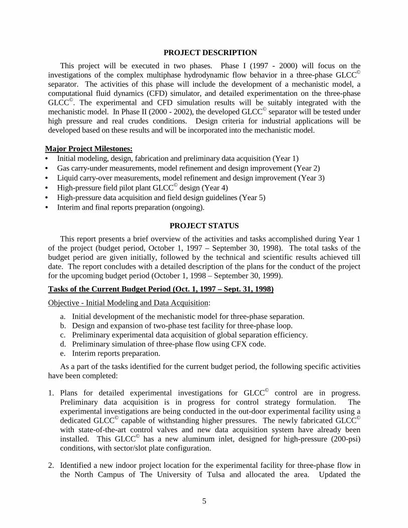
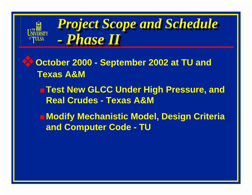
The objective of the proposed project is to expand the research activities of TUSTP tomultiphase oil/water/gas separation. This project will be executed in two phases. Phase I (1997- 2000) will focus on the investigations of the complex multiphase hydrodynamic flow behaviorin a three-phase GLCC. The activities of this phase will include the development of amechanistic model, a computational fluid dynamics (CFD) simulator, and detailedexperimentation on the three-phase GLCC. The experimental and CFD simulation results will besuitably integrated with the mechanistic model. In Phase II (2000 - 2002), the developed GLCCseparator will be tested under high pressure and real crudes conditions. This is crucial forvalidating the GLCC design for field application and facilitating easy and rapid technologydeployment. Design criteria for industrial applications will be developed based on these results
3
and will be incorporated into the mechanistic model by TUSTP. These essential ingredients willensure the development of the state-of-the-art technology in compact separation technology forthe 21st century.
INTRODUCTION
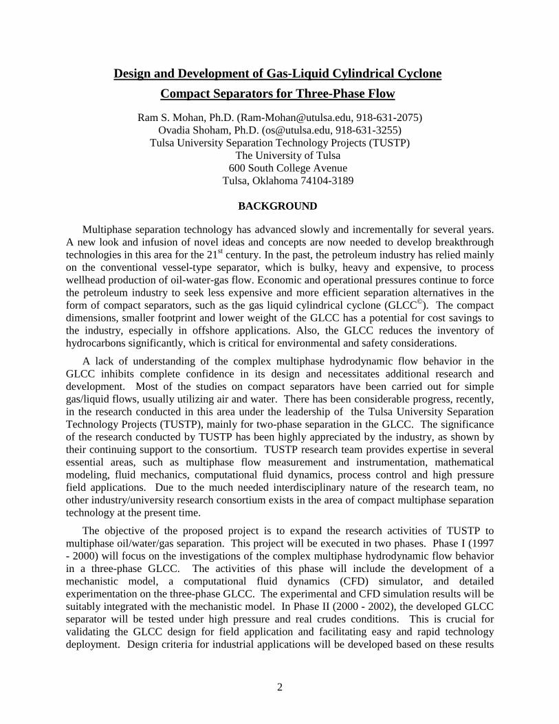
For many years, the Petroleum Industry has relied mainly on the conventional vessel-typeseparators. They are bulky, heavy and expensive in capital, installation and operation. Due toeconomic and operational pressures, the petroleum industry has recently shown interest in thedevelopment of innovative alternatives to the conventional separators. One such alternative isthe Gas-liquid Cylindrical Cyclone (GLCC). Unlike the conventional vessel type separators, theGLCC is simple, compact, low weight, low-cost, requires little maintenance, and is easy toinstall and operate. It is therefore gaining popularity as an easy-to-operate economicallyattractive, alternative to the conventional separator. The development ranking of the variousseparation technology alternatives are shown schematically in Fig. 1. As shown in this figure,conventional vessel-type separators have reached their maturity, except for some minorimprovements that are being incorporated, such as new developments of internal devices andcontrol systems. Large diameter vertical cyclones and hydro-cyclones have also been used bythe industry for some time. However, recent trends in development are focused towards newtype of compact separators such as the GLCC.
Dev
elop
men
t
GLCC’s
FWKOCyclones
Emerging
Gas Cyclones
Conventional Horizontal and Vertical Separators
Growth
Finger Storage Slug Catcher
Vessel TypeSlug Catcher
Maturity
Time
Hydrocyclones
Fig. 1 - ‘S’ Curve for Developmental Ranking of Separation Technology
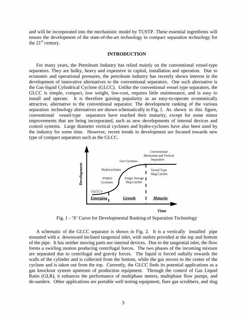
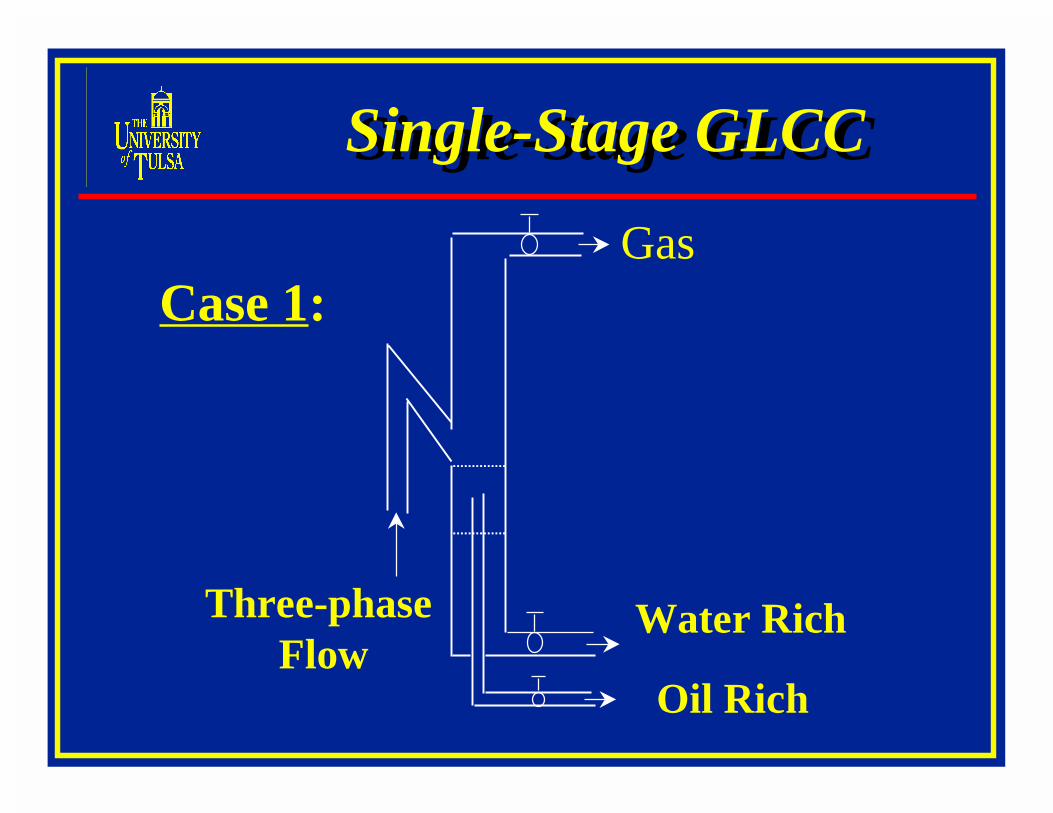
A schematic of the GLCC separator is shown in Fig. 2. It is a vertically installed pipemounted with a downward inclined tangential inlet, with outlets provided at the top and bottomof the pipe. It has neither moving parts nor internal devices. Due to the tangential inlet, the flowforms a swirling motion producing centrifugal forces. The two phases of the incoming mixtureare separated due to centrifugal and gravity forces. The liquid is forced radially towards thewalls of the cylinder and is collected from the bottom, while the gas moves to the center of thecyclone and is taken out from the top. Currently, the GLCC finds its potential applications as agas knockout system upstream of production equipment. Through the control of Gas LiquidRatio (GLR), it enhances the performance of multiphase meters, multiphase flow pumps, andde-sanders. Other applications are portable well testing equipment, flare gas scrubbers, and slug
4
catchers. The GLCC is also being considered for down hole separation, primary surfaceseparation (onshore and offshore) and sub sea separation.
GLCC’s that have already been installed and put to use in the field have successfullydemonstrated their applicability as two-phase separators. The concept is bound to have apronounced impact on the petroleum industry. However, a lack of understanding of thecomplex, multiphase, hydrodynamic flow behavior inside the GLCC inhibits completeconfidence in the GLCC design and necessitates additional research and development.Knowledge of the hydrodynamic behavior would enable GLCC users to correctly predict theperformance of the GLCC and to carry out appropriate design for all configurations andapplications.
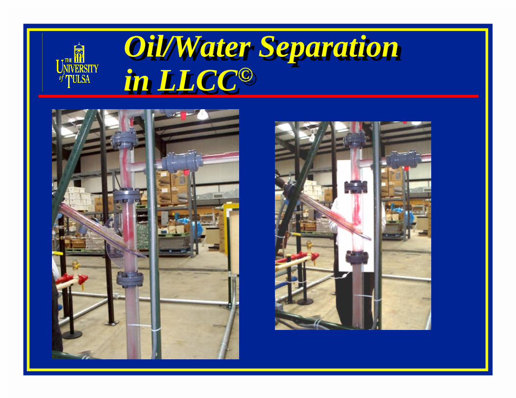
Most of the studies on compact separators have been carried out for simple gas/liquid flows,usually utilizing air and water. The fluid system existing in the industry is much morecomplicated with oil/water/gas three-phase flow. In this project, we propose to develop compactseparators for oil/water/gas flow and conduct detailed investigations of the three-phase flowbehavior. Initially, oil/water two-phase flow will be studied, utilizing a non emulsifying oil toavoid emulsions and dispersions. By all means, this will not be a trivial extension of gas/liquidflow due to the close densities of the two liquids, water and oil. Later, the gas phase will beadded to investigate whether compact separators will be effective as a water knockout device toremove the majority of the free water from multiphase mixtures.
OBJECTIVES
The overall objective of this five-year project (October, 1997 – September, 2002) is to expandthe state-of-the art of compact separation technology research from two-phase (gas-liquid) flowseparation to multiphase oil/water/gas flow production systems. The research aims at makingcompact separators predictable, reliable and a viable economical alternative to conventional vesseltype separators. Long-term cooperation with petroleum industry is envisaged in conducting thisproject to better understand, analyze and design compact separators for field application, andfacilitate easy and rapid technology deployment.
This report presents a brief overview of the activities and tasks accomplished during Year 1of the project (budget period, October 1, 1997 – September 30, 1998). The total tasks of thebudget period are given initially, followed by the technical and scientific results achieved tilldate. The report concludes with a detailed description of the plans for the conduct of the projectfor the upcoming budget period (October 1, 1998 – September 30, 1999).
Tasks of the Current Budget Period (Oct. 1, 1997 – Sept. 31, 1998)
Objective - Initial Modeling and Data Acquisition:
a. Initial development of the mechanistic model for three-phase separation.b. Design and expansion of two-phase test facility for three-phase loop.c. Preliminary experimental data acquisition of global separation efficiency.d. Preliminary simulation of three-phase flow using CFX code.e. Interim reports preparation.
As a part of the tasks identified for the current budget period, the following specific activitieshave been completed:
2. Identified a new indoor project location for the experimental facility for three-phase flow inthe North Campus of The University of Tulsa and allocated the area. Updated the
6
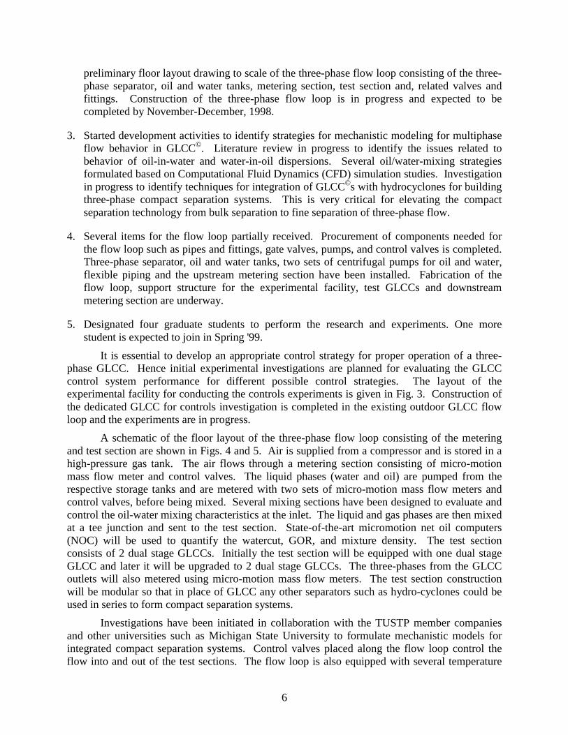
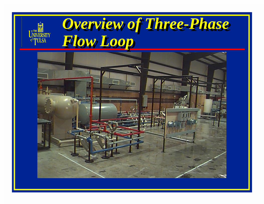
preliminary floor layout drawing to scale of the three-phase flow loop consisting of the three-phase separator, oil and water tanks, metering section, test section and, related valves andfittings. Construction of the three-phase flow loop is in progress and expected to becompleted by November-December, 1998.
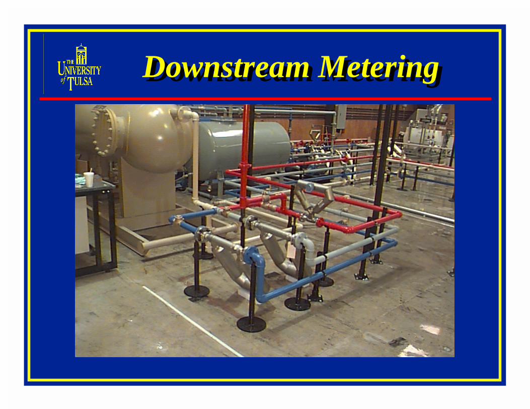
4. Several items for the flow loop partially received. Procurement of components needed forthe flow loop such as pipes and fittings, gate valves, pumps, and control valves is completed.Three-phase separator, oil and water tanks, two sets of centrifugal pumps for oil and water,flexible piping and the upstream metering section have been installed. Fabrication of theflow loop, support structure for the experimental facility, test GLCCs and downstreammetering section are underway.
5. Designated four graduate students to perform the research and experiments. One morestudent is expected to join in Spring '99.
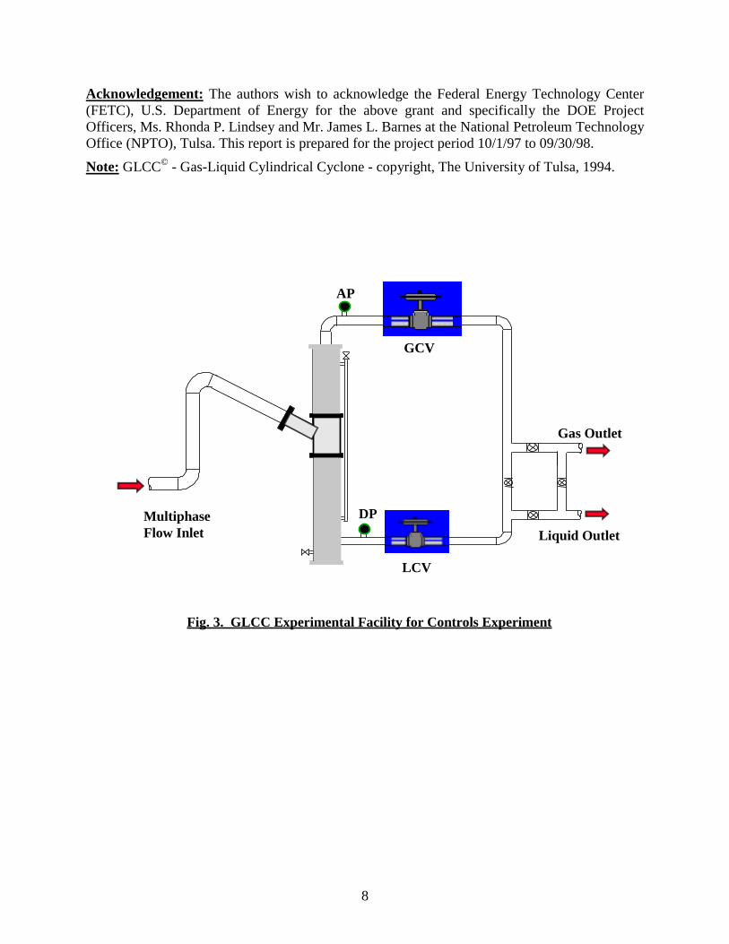
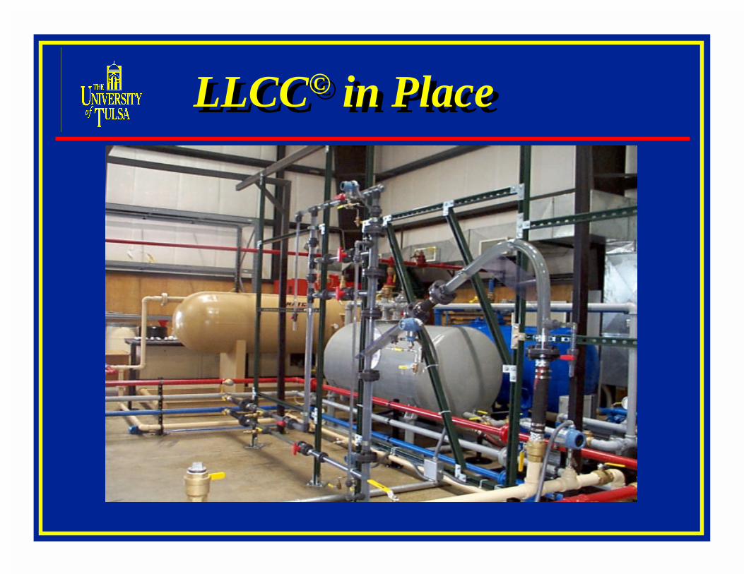
It is essential to develop an appropriate control strategy for proper operation of a three-phase GLCC. Hence initial experimental investigations are planned for evaluating the GLCCcontrol system performance for different possible control strategies. The layout of theexperimental facility for conducting the controls experiments is given in Fig. 3. Construction ofthe dedicated GLCC for controls investigation is completed in the existing outdoor GLCC flowloop and the experiments are in progress.
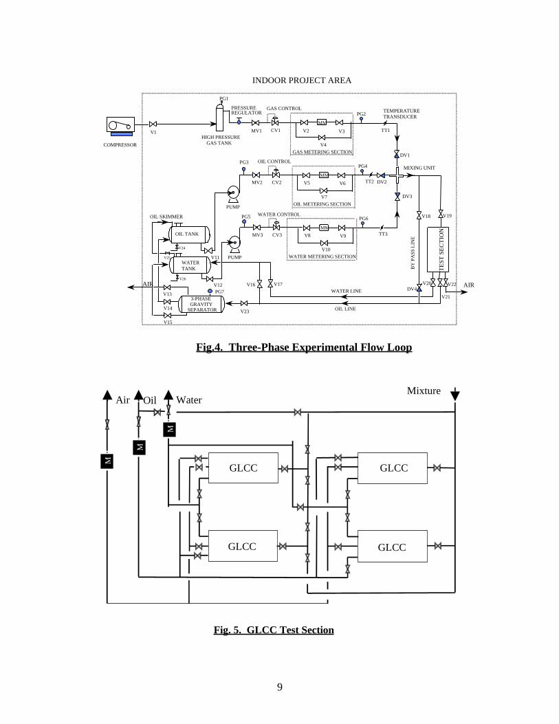
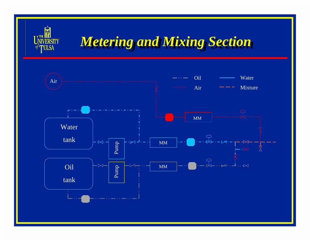
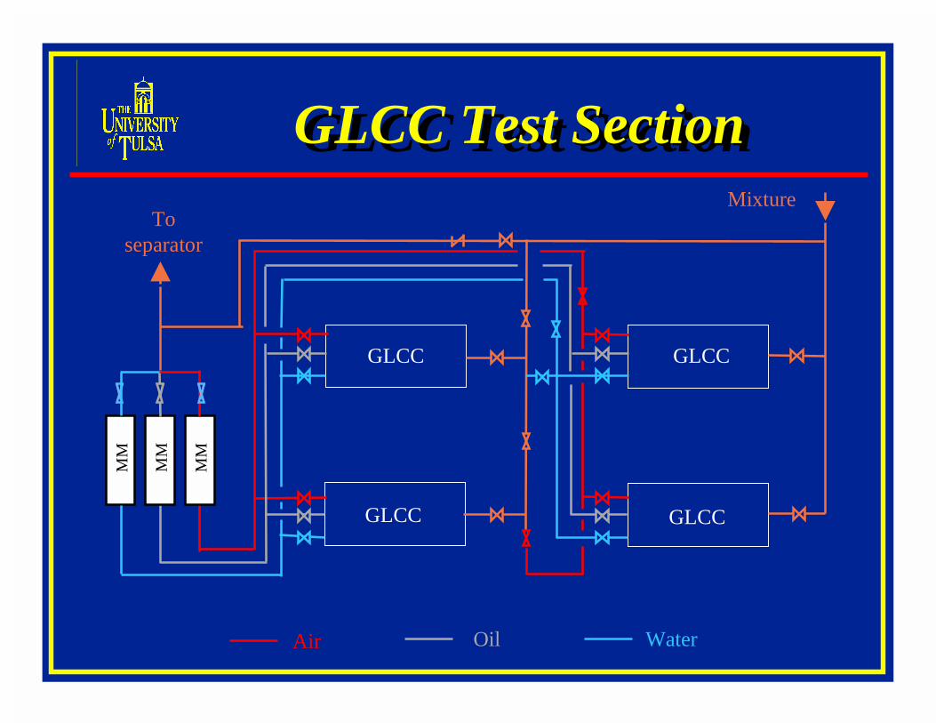
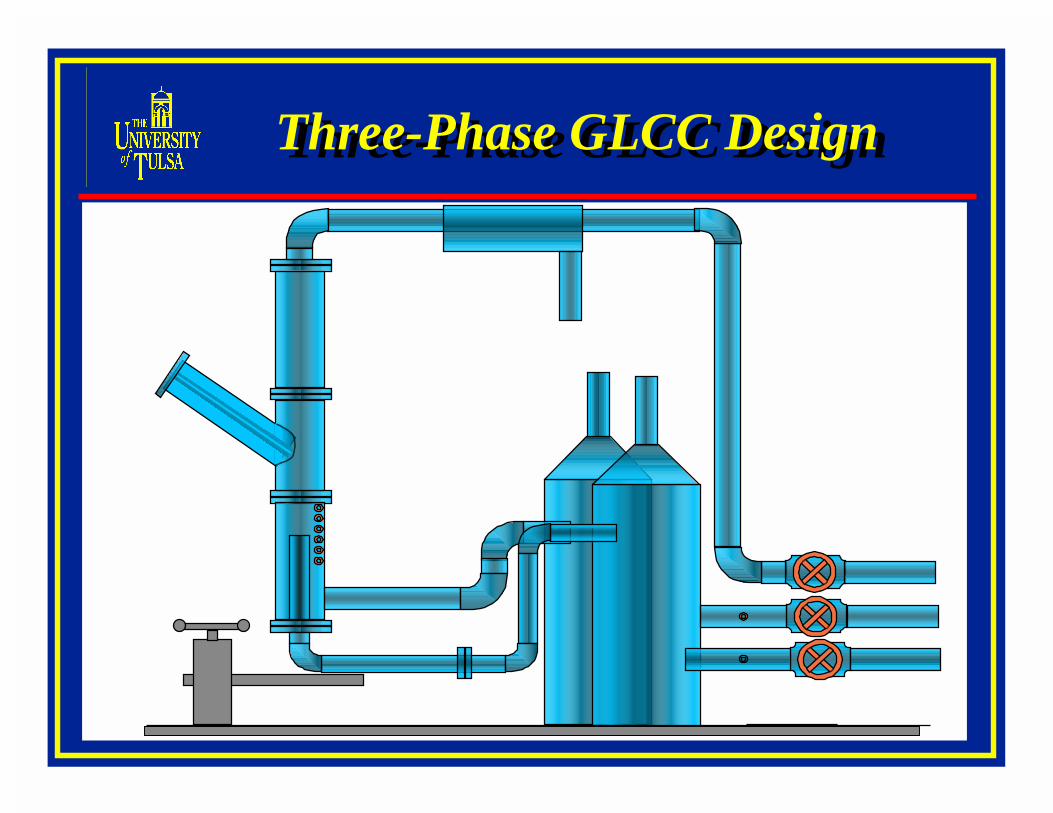
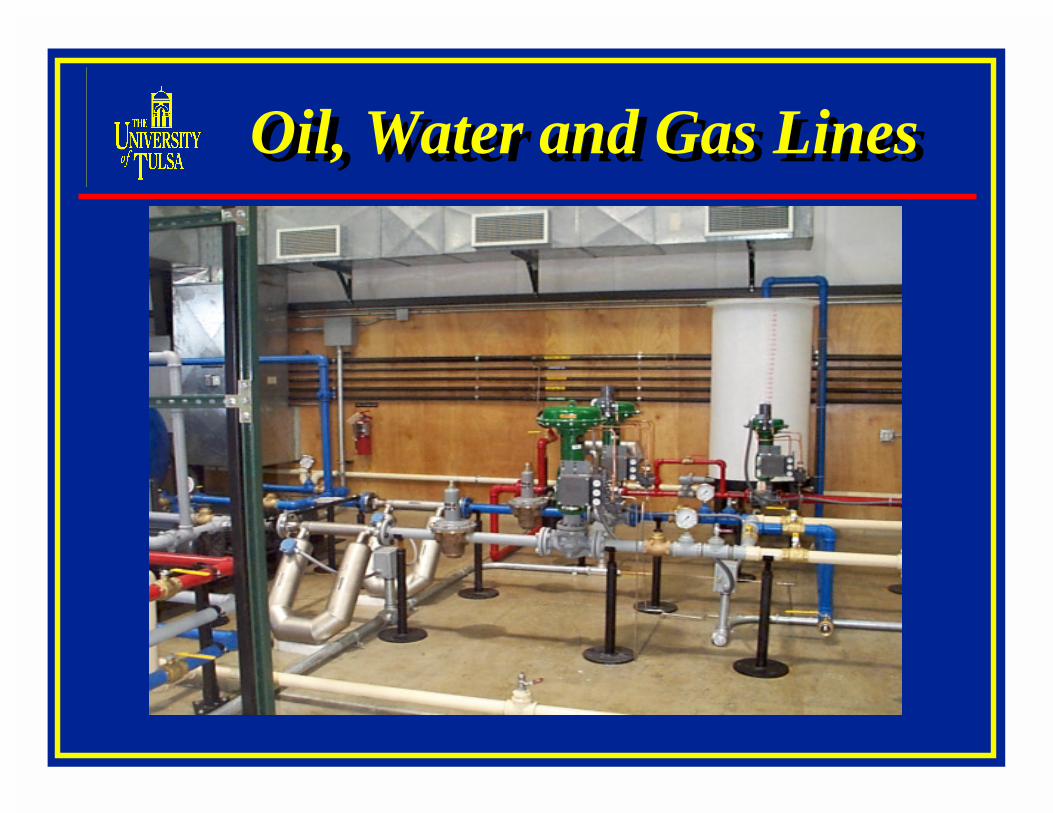
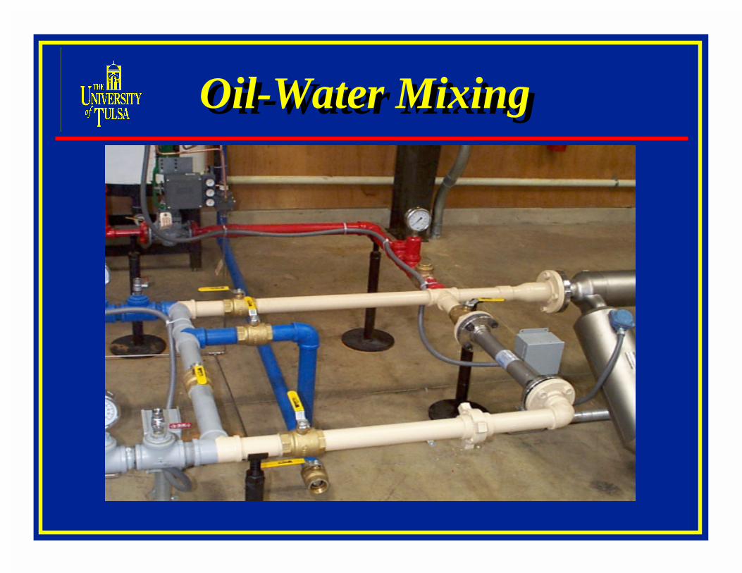
A schematic of the floor layout of the three-phase flow loop consisting of the meteringand test section are shown in Figs. 4 and 5. Air is supplied from a compressor and is stored in ahigh-pressure gas tank. The air flows through a metering section consisting of micro-motionmass flow meter and control valves. The liquid phases (water and oil) are pumped from therespective storage tanks and are metered with two sets of micro-motion mass flow meters andcontrol valves, before being mixed. Several mixing sections have been designed to evaluate andcontrol the oil-water mixing characteristics at the inlet. The liquid and gas phases are then mixedat a tee junction and sent to the test section. State-of-the-art micromotion net oil computers(NOC) will be used to quantify the watercut, GOR, and mixture density. The test sectionconsists of 2 dual stage GLCCs. Initially the test section will be equipped with one dual stageGLCC and later it will be upgraded to 2 dual stage GLCCs. The three-phases from the GLCCoutlets will also metered using micro-motion mass flow meters. The test section constructionwill be modular so that in place of GLCC any other separators such as hydro-cyclones could beused in series to form compact separation systems.
Investigations have been initiated in collaboration with the TUSTP member companiesand other universities such as Michigan State University to formulate mechanistic models forintegrated compact separation systems. Control valves placed along the flow loop control theflow into and out of the test sections. The flow loop is also equipped with several temperature
7
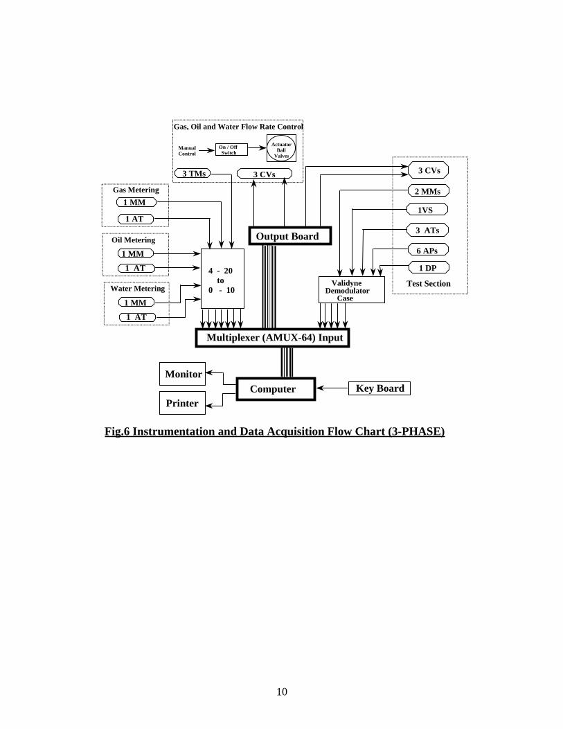
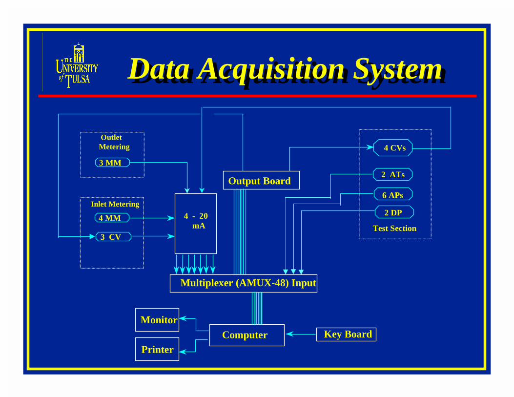
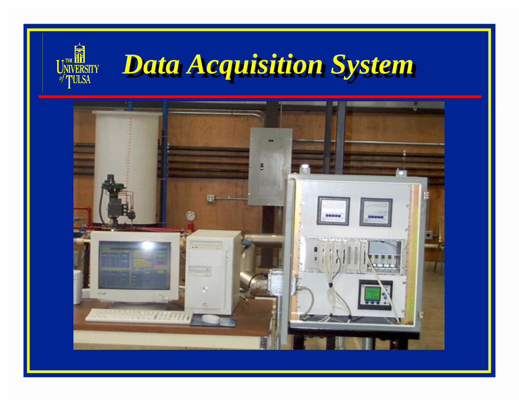
sensors and pressure transducers for measurement of the in-situ pressure and temperatureconditions. Installation of the data acquisition system will follow as soon as the construction ofthe flow loop is completed. A schematic of the typical data acquisition system for the flow loopis shown in Fig. 6.
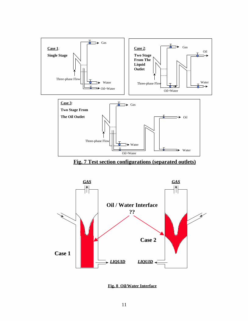
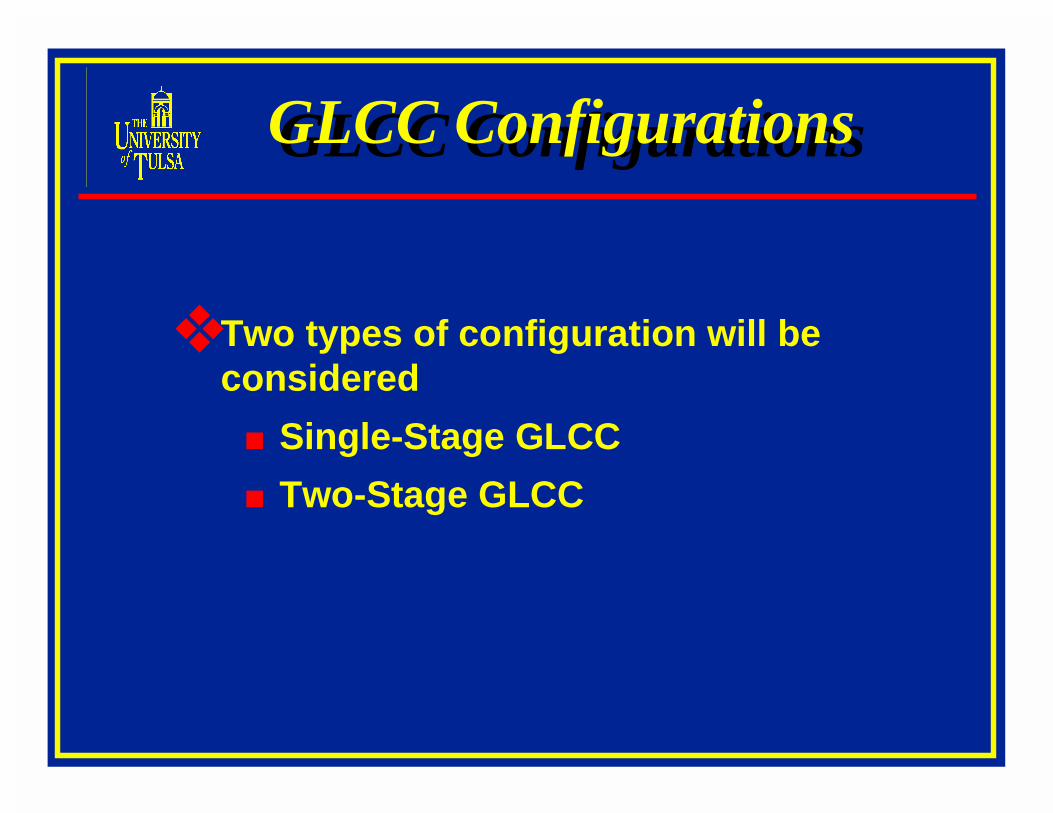
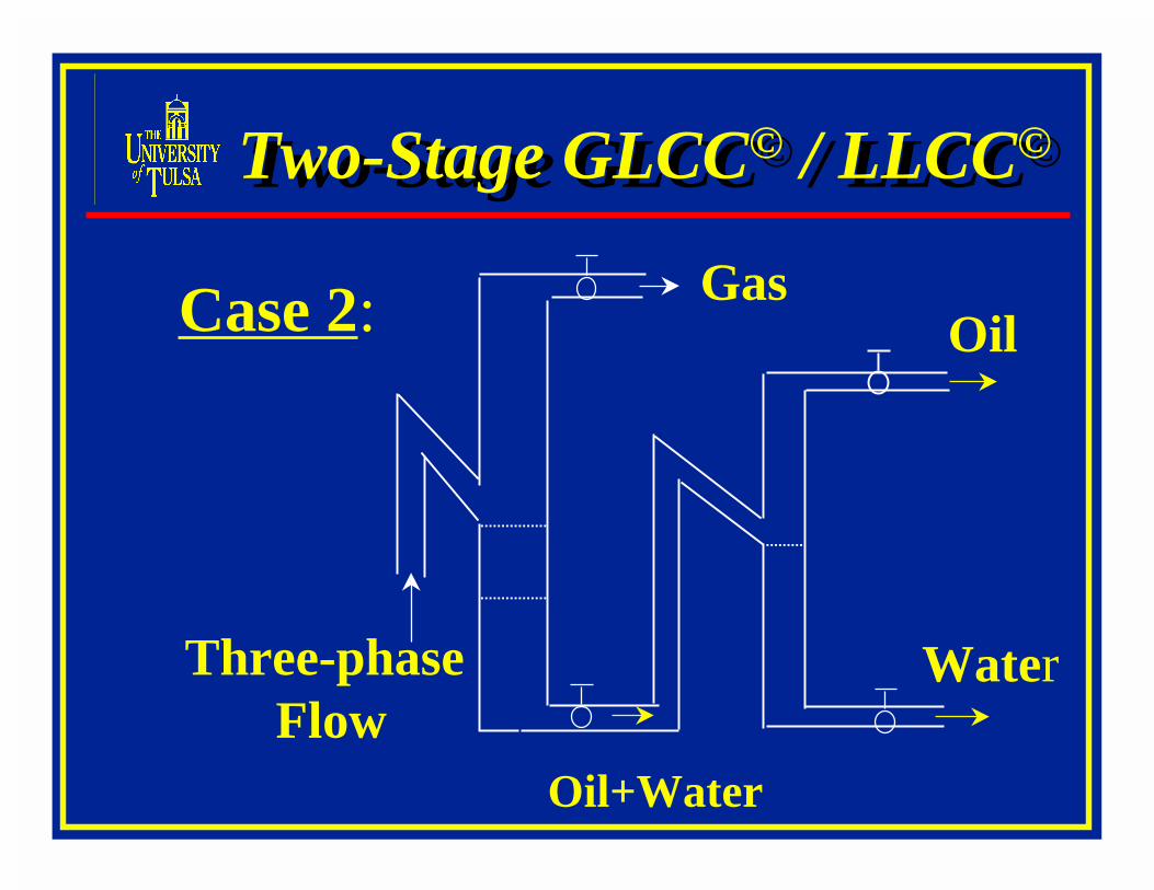
Three types of GLCC configurations will be considered for single stage GLCC and dualstage GLCC as shown in Fig. 7. The above flow loop can be used for both configurations. Thesetwo types of configurations will aid in investigating the function of GLCC as a bulk separatorand a full separator. Non-emulsifying oil will be used as the experimental fluid. Flow runs willbe conducted initially by using oil-water two-phase and gas will be added as the third phase later.Two types of oil-water interface are possible as shown in Fig. 8. Initial investigation will focuson identifying the nature of oil-water interface and formulation of appropriate separationstrategies for the GLCC. Several literature have been identified to provide more information intothe nature of the oil-water interface for cyclonic separators of low G-forces such as the GLCCs.
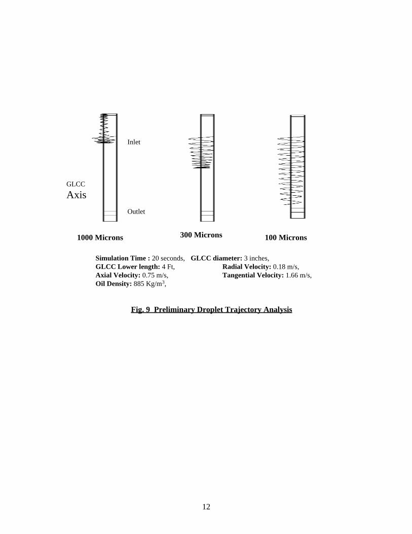
As an essential component of the mechanistic model development for three-phase flow,preliminary Computational Fluid Dynamic simulations have been conducted to investigate theoil-water separation in a two-phase liquid-liquid mixture with water (denser liquid) as themedium. The results of CFD flow-simulation studies using the computer code CFX 4.1 areshown in Fig. 9 for three different oil droplet sizes. The simulation time was 20 seconds, the oilspecific gravity was 0.885, and the GLCC lower part length and diameter were 4-ft and 3-inchesrespectively. The magnitudes of radial, axial and tangential velocity components are also givenin Fig. 9, which is typical of normal GLCC operating conditions. The simulation results of thedroplet trajectory indicate that, it is much easier to separate oil droplets of diameters 1000 micron(1mm) and above from the denser water medium. It is also observed that at diameters of 100microns and below there is a much higher probability of oil particle carry-under into the waterstream. This is a very significant initial result as it gives a basis for oil droplet monitoring,predicting the oil carry-under and developing strategies for ensuring separation efficiency ofthree-phase separators. Detailed investigations are planned in the second project year (October,1998 – September, 1999) to conduct simulation studies for other operating conditions, namelydifferent flow velocities, different fluid densities, and also verification with experimental results.
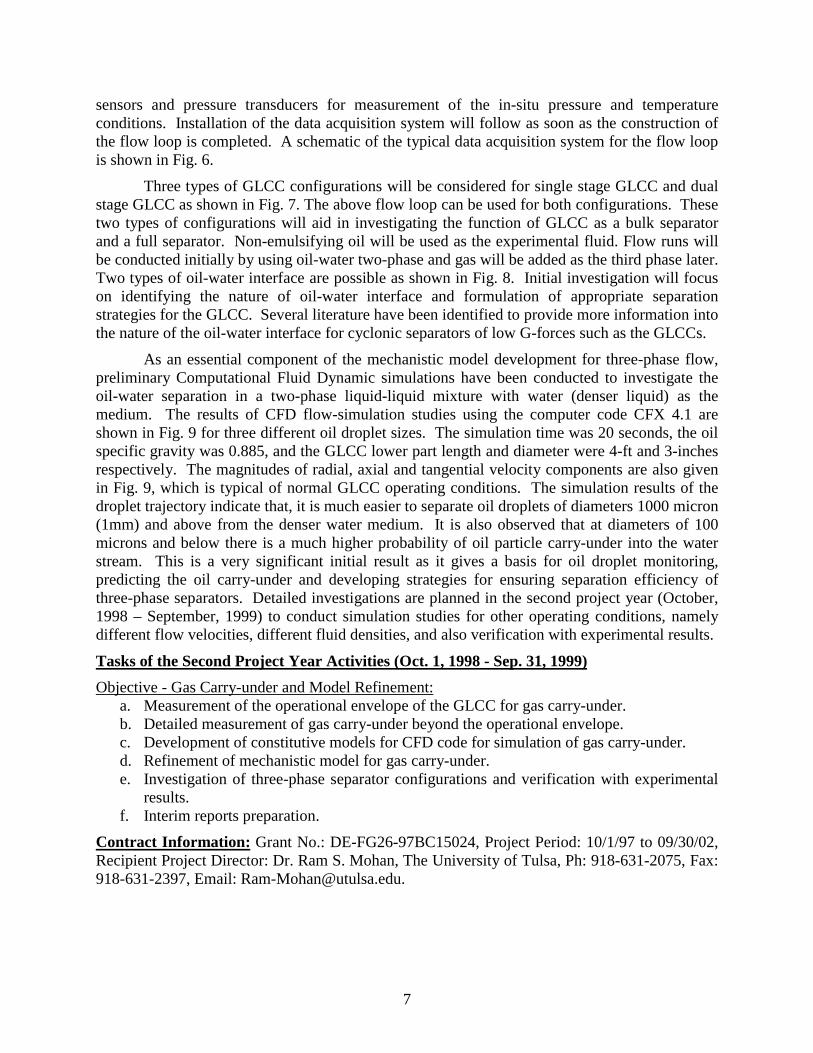
Tasks of the Second Project Year Activities (Oct. 1, 1998 - Sep. 31, 1999)
Objective - Gas Carry-under and Model Refinement:a. Measurement of the operational envelope of the GLCC for gas carry-under.b. Detailed measurement of gas carry-under beyond the operational envelope.c. Development of constitutive models for CFD code for simulation of gas carry-under.d. Refinement of mechanistic model for gas carry-under.e. Investigation of three-phase separator configurations and verification with experimental
results.f. Interim reports preparation.
Contract Information: Grant No.: DE-FG26-97BC15024, Project Period: 10/1/97 to 09/30/02,Recipient Project Director: Dr. Ram S. Mohan, The University of Tulsa, Ph: 918-631-2075, Fax:918-631-2397, Email: [email protected].
8
Acknowledgement: The authors wish to acknowledge the Federal Energy Technology Center(FETC), U.S. Department of Energy for the above grant and specifically the DOE ProjectOfficers, Ms. Rhonda P. Lindsey and Mr. James L. Barnes at the National Petroleum TechnologyOffice (NPTO), Tulsa. This report is prepared for the project period 10/1/97 to 09/30/98.