Page 1
© Green Steel for Europe Consortium, 2021
Technology Assessment and
Roadmapping
(Deliverable 1.2)
Monika Draxler, Axel Sormann (K1-MET)
Tobias Kempken, Thorsten Hauck (BFI)
Jean-Christophe Pierret, Jean Borlee (CRM)
Antonello Di Donato, Michele De Santis (CSM)
Chuan Wang (Swerim)
March 2021
Page 2
1
This project has received funding from the European Union under grant
agreement NUMBER — 882151 — GREENSTEEL
The information and views set out in this document do not necessarily reflect the official opinion of
the European Commission. The European Commission does not guarantee the accuracy of the
data included in this document. Neither the European Commission nor any person acting on the
European Commission’s behalf may be held responsible for the use which may be made of the
information contained therein.
Page 3
2
Table of contents
Table of contents .............................................................................................................................. 2
List of figures .................................................................................................................................... 4
List of tables ..................................................................................................................................... 5
List of symbols, indices, acronyms and abbreviations ..................................................................... 6
Executive summary .......................................................................................................................... 8
1 Introduction .............................................................................................................................. 16
2 Technology assessment ......................................................................................................... 19
2.1 Carbon direct avoidance ................................................................................................. 21
2.1.1 Hydrogen-based direct reduction ............................................................................ 21
2.1.2 Hydrogen plasma smelting reduction ...................................................................... 25
2.1.3 Alkaline iron electrolysis .......................................................................................... 27
2.1.4 Molten oxide electrolysis ......................................................................................... 30
2.2 Carbon capture and usage ............................................................................................. 32
2.2.1 Carbon oxide conversion ......................................................................................... 32
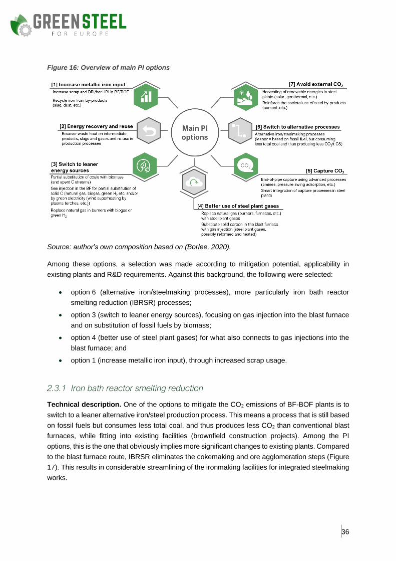
2.3 Process integration ......................................................................................................... 35
2.3.1 Iron bath reactor smelting reduction ........................................................................ 36
2.3.2 Gas injection into blast furnace ............................................................................... 39
2.3.3 Substitution of fossil energy carriers with biomass ................................................. 44
2.3.4 High-quality steelmaking with increased scrap usage ............................................ 46
2.4 Auxiliary processes ......................................................................................................... 49
2.4.1 CO2 capture ............................................................................................................. 49
2.4.2 Water electrolysis .................................................................................................... 51
2.5 Summary of the assessed technologies ......................................................................... 53
3 Setup of technology routes ..................................................................................................... 55
3.1 Technology routes based on optimised BF-BOF ............................................................ 55
3.1.1 Extent of modifications to be implemented in existing plants ................................. 56
3.1.2 Framework conditions ............................................................................................. 57
3.2 Technology routes based on direct reduction ................................................................. 58
3.2.1 Extent of modifications to be implemented in existing plants ................................. 59
3.2.2 Framework conditions ............................................................................................. 60
3.3 Technology routes based on smelting reduction ............................................................ 60
3.3.1 Enhanced IBRSR technology route ........................................................................ 60
Page 4
3
3.3.2 Technology route based on hydrogen plasma smelting reduction ......................... 61
3.4 Technology routes based on iron ore electrolysis .......................................................... 62
3.4.1 Technology route based on alkaline iron electrolysis ............................................. 62
3.4.2 Technology route based on molten oxide electrolysis ............................................ 64
4 Technology routes roadmapping ............................................................................................ 65
4.1 Technology routes based on optimised BF-BOF ............................................................ 67
4.2 Technology routes based on direct reduction ................................................................. 71
4.3 Technology routes based on smelting reduction ............................................................ 74
4.4 Technology routes based on iron ore electrolysis .......................................................... 76
5 Concluding remarks ................................................................................................................ 78
Bibliography .................................................................................................................................... 80
Annex I ............................................................................................................................................ 84
Page 5
4
List of figures
Figure 1: Overview of the set-up of technology routes in comparison to the integrated steelmaking
route ................................................................................................................................................ 13
Figure 2: Roadmap of selected CO2 mitigation technologies ........................................................ 15
Figure 3: Overview of actual steel production routes ..................................................................... 17
Figure 4: Decarbonisation technologies according to the pathways classification and their
supporting technologies within the European steel industry .......................................................... 19
Figure 5: Overview of greenhouse gas emissions classified into three scopes based on the GHG
Protocol ........................................................................................................................................... 21
Figure 6: Schematic and simplified view of a shaft furnace for H2-DR .......................................... 22
Figure 7: Graphical overview of CO2 mitigation potential and TRL development (H2-DR) ........... 25
Figure 8: Schematic and simplified view of hydrogen plasma smelting reduction ........................ 26
Figure 9: Graphical overview of CO2 mitigation potential and TRL development (HPSR) ............ 27
Figure 10: Schematic and simplified view of alkaline iron electrolysis .......................................... 28
Figure 11: Graphical overview of CO2 mitigation potential and TRL development (alkaline iron
electrolysis) ..................................................................................................................................... 30
Figure 12: Schematic and simplified view of molten oxide electrolysis ......................................... 31
Figure 13: Graphical overview of CO2 mitigation potential and TRL development (molten oxide
electrolysis) ..................................................................................................................................... 32
Figure 14: Schematic and simplified visualisation of CCU ............................................................ 33
Figure 15: Graphical overview of CO2 mitigation potential and TRL development (CCU) ............ 35
Figure 16: Overview of main PI options ......................................................................................... 36
Figure 17: Comparison of the integrated steelmaking route (a) and the HIsarna® technology (b) 37
Figure 18: HIsarna® technology ..................................................................................................... 37
Figure 19: Graphical overview of CO2 mitigation potential and TRL development (IBRSR) ......... 39
Figure 20: Schematic view of TGR-BF ........................................................................................... 40
Figure 21: ‘COURSE50’ process scheme ...................................................................................... 41
Figure 22: Graphical overview of CO2 mitigation potential and TRL development (gas injection into
blast furnace) .................................................................................................................................. 43
Figure 23: Roadmap for the Japan Iron and Steel Federation long-term vision for climate change
mitigation ........................................................................................................................................ 44
Figure 24: Graphical overview of CO2 mitigation potential and TRL development (substitution by
biomass) ......................................................................................................................................... 46
Figure 25: Overview of mitigation technologies in the iron and steel industry ............................... 54
Figure 26: Schematic and simplified view of a combination of mitigation technologies based on
conventional BF-BOF ..................................................................................................................... 56
Figure 27: Schematic and simplified view of the H2-DR-EAF technology route ............................ 59
Figure 28: Schematic and simplified view of the enhanced IBRSR technology route ................... 61
Figure 29: Schematic and simplified view of the technology route based on HPSR ..................... 62
Page 6
5
Figure 30: Schematic and simplified view of the alkaline iron electrolysis technology route ........ 63
Figure 31: Schematic and simplified view of the molten oxide electrolysis technology route ....... 64
Figure 32: Technological landscape of Europe’s iron and steelmaking production sites utilising blast
furnaces and/or basic oxygen furnaces (EU28, 2020) ................................................................... 66
Figure 33: Technological landscape of Europe’s iron and steelmaking production sites utilising
electric arc furnaces (simplified, EU28, 2020) ............................................................................... 67
Figure 34: Roadmap of breakthrough technology routes based on optimised BF-BOF ............... 70
Figure 35: Roadmap of the technology routes based on direct reduction ..................................... 73
Figure 36: Roadmap of the technology routes based on smelting reduction ................................ 75
Figure 37: Roadmap for the technology routes based on iron electrolysis ................................... 76
Figure 38: CO2 mitigation potential and TRL of the selected technologies ................................... 79
List of tables
Table 1: Overview of low-carbon iron and steelmaking technologies (% of average BF-BOF plant;
CS - crude steel; ind. deployed - industrially deployed; CAPEX - capital expenditure; OPEX -
operational expenditure; impl. – implementation; neg. - negative) ................................................ 10
Table 2: Estimated TRL development of H2-DR (100% H2) .......................................................... 24
Table 3: Estimated TRL development of hydrogen plasma smelting reduction ............................ 26
Table 4: Estimated TRL development of alkaline iron electrolysis ................................................ 29
Table 5: Estimated TRL development of molten oxide electrolysis ............................................... 31
Table 6: Estimated TRL development of carbon oxide conversion ............................................... 34
Table 7: Estimated TRL development of iron bath reactor smelting reduction.............................. 38
Table 8: Estimated TRL development of gas injection into the blast furnace ................................ 42
Table 9: Estimated TRL development of substitution of fossil energy carriers with biomass ....... 46
Table 10: Overview of TRL development regarding high-quality steelmaking with increased scrap
usage .............................................................................................................................................. 49
Table 11: Estimated TRL development of CO2 capture ................................................................. 51
Table 12: Estimated TRL development of water electrolysis ......................................................... 52
Table 13: Estimated mitigation potential of specific technology routes based on optimised BF-BOF
........................................................................................................................................................ 57
Table 14: European steelmaking sites equipped with blast furnaces and basic oxygen furnaces
(2020) ............................................................................................................................................. 84
Table 15: European steelmaking sites equipped with electric arc furnaces (2020) ...................... 85
Page 7
6
List of symbols, indices, acronyms and abbreviations
AEL Alkaline water electrolysis
AIE Alkaline iron electrolysis
Ar Argon
As Arsenic
B Boron
BF Blast furnace
Bi Bismuth
BOF Basic oxygen furnace
C Carbon
CAPEX Capital expenditure
CCfD Carbon contracts for difference
CCS Carbon capture and storage
CCU Carbon capture and usage
CCUS Carbon capture and usage or storage
CDA Carbon direct avoidance
CE Circular economy
CO Carbon monoxide
CO2 Carbon dioxide
CS Crude steel
Cu Copper
DR Direct reduction
DRI Direct reduced iron
EAF Electric arc furnace
EU European Union
H2 Hydrogen
H2-DR Hydrogen-based direct reduction
H2O Water
HBI Hot briquetted iron
HCl Hot compacted iron
HTEL High temperature electrolysis
HPSR Hydrogen plasma smelting reduction
IBRSR Iron bath reactor smelting reduction
Page 8
7
Mo Molybdenum
MOE Molten oxide electrolysis
NG-DR Natural gas direct reduction
N2 Nitrogen
O2 Oxygen
OPEX Operational expenditure
PEM Polymer electrolyte membrane
PI Process integration
R&D Research and development
Sb Antimony
SCU Smart carbon usage
Sn Tin
t Ton
TGR-BF Top gas recycling – blast furnace
TRL Technology readiness level
Page 9
8
Executive summary
To meet the 2050 European climate and energy targets, the iron and steel industry’s CO2 footprint
needs to reduce by 80-95%, compared to 1990 levels, by 2050. This can only be done if adequate
and innovative solutions are established to shift current processes towards carbon-lean production.
The Green Steel for Europe project aims, inter alia, to provide transparency about the technologies
needed and their impact, and the barriers to be overcome and the remedies needed to initiate the
crucial next steps.
Deliverable 1.2 provides the technological foundation for the evaluation of CO2 mitigation strategies
with specific low-carbon technologies, and for implementing complete technology routes in the
European steel industry. It summarises iron and steelmaking technologies, supporting technologies
and technology routes, describing their technological approaches, their current maturity (in terms
of readiness level) and their expected development, and the influencing framework conditions. This
deliverable contains the preliminary results of the Green Steel for Europe project. The concluding
results, including the development of scenarios, can be found in subsequent deliverables.
The CO2 mitigation pathways, which are currently being addressed in the European steel industry,
are carbon direct avoidance (CDA), process integration (PI) and carbon capture and usage (CCU).
The parallel circular economy strategy targets a ‘zero waste’ concept and complements the above-
mentioned pathways as an overarching approach. The CDA pathway primarily focuses on the
development of new steelmaking processes using fossil-free reductants and (renewable or clean)
energy sources to produce steel from virgin iron ore, thereby avoiding the generation of carbon
oxides and its emissions. The PI pathway concerns possible modifications or adaptations to
existing steel plants in order to reduce greenhouse emissions, and can be complemented by CCU
and/or carbon capture and storage (CCS). CCU consists of the capture of CO2 or CO from steel
production process gases and the production of further valuable carbon-based products from
captured fossil carbon, thus mitigating emissions caused by fossil resources in their conventional
production chains.
The following technologies were identified as the most relevant within these pathways:
• hydrogen-based direct reduction (H2-DR)
• hydrogen plasma smelting reduction (HPSR)
• alkaline iron electrolysis (AIE)
• molten oxide electrolysis (MOE)
• carbon oxide conversion (CCU)
• iron bath reactor smelting reduction (IBRSR)
• gas injection into the blast furnace
• substitution of fossil energy carriers by biomass
• high-quality steelmaking with increased scrap usage.
The selection of iron and steelmaking technologies is based on desktop research of various global
publications, a comprehensive stakeholder survey and the outcomes from the previous RFCS
Project LowCarbonFuture - Exploitation of projects for Low-Carbon Future Steel Industry (Grant
Agreement No. 800643).
Page 10
9
The majority of the identified technologies have a moderate maturity level, with technology
readiness levels between 5 and 7. Certain technologies, such as hydrogen plasma smelting
reduction or molten oxide electrolysis, have high CO2 mitigation potential but are currently at low
maturity. Correspondingly, a high number of research and development (R&D) projects are needed,
in particular regarding the processes and their upscaling, as well as the related plant technologies,
auxiliary processes, material processing and a large number of measurement and control aspects.
Table 1 provides an overview of the technologies and their main data.
Page 11
10
Table 1: Overview of low-carbon iron and steelmaking technologies (% of average BF-BOF plant;
CS - crude steel; ind. deployed - industrially deployed; CAPEX - capital expenditure; OPEX -
operational expenditure; impl. – implementation; neg. - negative)
Technology TRL development
Economic assessment Reference projects1 2020 2030 2050
Hydrogen-based direct
reduction (100% H2)
TRL 6-8 TRL 7-
9
TRL 9 (ind.
deployed)
20-80% cost increase; production costs: ~€532-640/t CS
HYBRIT, SALCOS, tkH2Steel, Hydrogen Hamburg
Hydrogen plasma
smelting reduction
TRL 5 TRL 6
TRL 9 (ind.
deployed)
No information on CAPEX or OPEX
SuSteel
Alkaline iron electrolysis
TRL 5-6 TRL 6-
8 TRL 9
CAPEX + OPEX: ~€645-828/t CS
ULCOS (SP5-13-14), IERO, VALORCO, SIDERWIN
Molten oxide electrolysis
TRL 2 TRL 3-
4 TRL 9
CAPEX: ~€1 K/t CS annual capacity OPEX: increase of 50-80% compared to conventional route
ULCOS, IERO, VALORCO
Carbon oxide conversion
TRL 8 (conversion)
TRL 4-5 (impl.)
TRL 9 Ind.
deployed
CAPEX increase of ~€13/t CS OPEX increase of €408-629/t CS
Carbon2Chem, Carbon4PUR, STEELANOL
Iron bath reactor
smelting reduction
TRL 6 TRL 8 Ind.
deployed
CAPEX: €500 M (for a 1.15 Mt/year plant excl. O2 plant) Neg. OPEX (-25 to -€30/t CS), due to efficiency gains
HIsarna
Gas injection into the blast
furnace
TRL 5-8 (preparation
/ gas reforming) TRL 9 (H2
rich)
TRL 8-9
Ind. deployed (in 2040)
CAPEX: €80-110 / €110-150/t CS (without / with CCUS) OPEX: €0-10 / €40-50/t CS (without / with CCUS).
ULCOS
Substitution of fossil energy
carriers by biomass
TRL 2-7 TRL 8
TRL9 and ind. depl. in 2035
CAPEX relatively low and OPEX depends mainly on the raw materials
SHOCOM, GREENEAF2, ACASOS
High-quality steelmaking
with increased
scrap usage
TRL 4-8 TRL 7-
9 Ind.
deployed OPEX: significant depending on the scrap price
FLEXCHARGE, ADAPTEAF, SSIA, LCS
Source: author’s own composition.
Several technologies can be combined in order to raise the overall CO2 mitigation potential above
their individual limits. CO2 capture and H2 generation are the main auxiliary processes connected
to several of the technologies. As H2 can be extracted from fossil fuels and biomass, water, or a
1 This list of reference projects is not exhaustive.
Page 12
11
mix of both, there are multiple production processes available such as reforming of gas, gasification
(biomass, waste etc.) or water electrolysis.
The analyses showed that for most technologies, a huge amount of additional clean energy is
needed and that the material cycles in the plants will be fundamentally influenced. Moreover, many
technologies imply a significant increase in terms of CAPEX (due to the need to replace main parts
of the upstream process chain) and OPEX (mostly due to expensive renewable energy supply).
The exchange of fossil energy sources by biomass usually needs less changes within the process
chain; however, its use is strongly limited by the (local) availability of biomass resources.
The technologies described in this report focus on the predominant trends within the EU, supported
by a literature review relating to non-EU countries. In Japan, the COURSE50 programme is aiming
to mitigate CO2 emissions in steel production by using several approaches, including hydrogen gas
injection into the blast furnace (BF) and carbon capture and storage. The POSCO programme in
South Korea focuses on the carbon-lean FINEX process, pre-reduction, heat recovery of sinter,
carbon capture and storage as well as hydrogen-based reduction of iron ore. In the US, steelmaking
by molten oxide electrolysis, hydrogen flash smelting and CO2 capture and separation are being
investigated. Australia is working on two programmes regarding the utilisation of biomass and heat
recovery from molten slags through dry granulation in blast furnaces.
The iron and steelmaking technologies within each pathway (CDA, PI, CCU) can be considered as
individual modular components (mitigation options) within the complete steel production chain.
Technology routes integrate these components into a full system (process chain), which includes
upstream operations (transformation of raw materials into intermediate steel products) and
downstream applications (production of final shaped and coated products). The compilation of
technologies to technology routes (including the integration into existing/new production chains)
needs substantial additional effort, both with respect to R&D activities and to accompanying
investments needed. Combining mitigation technologies in technology routes is by essence not
limited to a specific mitigation pathway (CDA, PI, CCU) but may include elements from all of them.
The CO2 emission of downstream processes is much lower than from ore-based upstream
processes. Therefore, the focus lies on upstream applications and scope 1 (direct emissions) and
scope 2 (indirect emissions from the production of required energy) emissions.
Four promising technology routes were identified within the project work as highly relevant (but
non-exclusive) examples. The first one is based on conventional BF-BOF plants (blast furnace,
basic oxygen furnace), into which a number of add-on CO2 mitigation technologies are incorporated
(PI, CCU). This route can be considered a short-term solution. The second is based on the
utilisation of hydrogen-based direct reduction, in which all ironmaking and steelmaking units are
replaced by new production methods. The third technology route comprises technologies based on
smelting reduction. This includes, on the one hand, the iron bath reactor smelting reduction option,
in which the ironmaking part is replaced and, on the other hand, hydrogen plasma smelting
reduction, which enables the direct transformation of iron ore into liquid steel. The last technology
route refers to the electricity-based steelmaking by iron ore electrolysis, which represents new
production methods.
The illustration below (Figure 1) provides a comparative view of the technology routes (green) and
the integrated primary steel production route (grey). The process chain is visualised from top to
bottom of the figure. The objective is to demonstrate to which extent alterations occur. The route
Page 13
12
based on conventional BF-BOF and the enhanced iron bath reactor smelting reduction technology
route show a horizontal change (i.e. with remaining BOF) as opposed to a widespread vertical
alteration within the hydrogen-based direct reduction-electric arc furnace (H2-DR-EAF) route and
the electrolysis-based technology route. The green indications within the flow diagrams show the
modifications, whereas the grey-coloured annotations symbolise unchanged procedures.
Although the main existing process units are not replaced with new technologies for the proposed
CO2 mitigation route based on conventional BF-BOF, considerable changes must be carried out in
conventional plants. To reach significant mitigation through this technology route, considerable
investments are required for the add-on technologies (e.g. carbon capture, usage and storage,
biomass preparation, gas preparation and blast furnace gas injection systems).
For the H2-DR-EAF route, the technology route based on hydrogen plasma smelting reduction and
the technology routes based on iron ore electrolysis, the full ironmaking and steelmaking capacities
of existing BF-BOF plants have to be replaced. The effort is almost comparable to greenfield
conditions. The data provided in the figure regarding this route refer to the breakthrough technology
with (almost) complete usage of hydrogen as reducing gas for direct reduction.
The smelting reduction technology route replaces the full ironmaking process in conventional
plants; further significant investments are required for add-on technologies (e.g. carbon capture,
usage and storage and biomass preparation) to achieve extensive CO2 mitigation.
Starting from individual iron and steelmaking technologies, the roadmaps for the proposed
breakthrough technology routes have been created (Figure 2). They indicate the progress and the
research needs for each technology involved along the timeline. The needs for integrating the
technologies into a complete breakthrough process chain are also visualised. Each line describes
one technology. Starting in 2020 (current technology readiness level), the technology readiness
level development is shown from left (short-term) to right (long-term) both graphically (grey shaded
area) and numerically.
Consistent with all other deliverables within the project, ‘short-term’ refers to the period up to about
2030, while ‘long-term’ refers to a time after 2040. As soon as TRL 9 – and thus the maturity for
first industrial deployment – is reached, the mitigation potential is presented in a circular diagram.
Research needs were grouped and listed in the associated time period.
Page 14
13
Figure 1: Overview of the set-up of technology routes in comparison to the integrated steelmaking route
Source: author’s own composition.
Page 15
14
An important intermediate step towards the deployment of the H2-DR-EAF technology route is the
direct reduction with natural gas which has been an industrially established technology for a long
time. Also, with natural gas the direct reduction technology (NG-DR-EAF) provides a significant
CO2 mitigation potential compared to the conventional BF-BOF-route, and thus, a promising short-
term option. The share of hydrogen as a partial substitute for natural gas can be increased stepwise
towards the possible later target of complete hydrogen-based reduction. This allows a gradual
enrichment with hydrogen on industrial scale and enables a flexible increase of hydrogen
concentration depending on availability, price, and technical requirements. Regarding the time
scale for industrial deployment, this results in the option of direct reduction plants being built as of
now (depending on the individual investment cycles of the respective plants) and their shift towards
increased hydrogen usage as soon as possible depending on its availability. Natural gas-based
direct reduction can be complemented by CCU and/or carbon capture and storage; the realisation
relies on the specific situation of the individual steel production site.
Another promising short-term option is to replace part of the fossil coal used in different plants (e.g.
coking plant, sinter plant and blast furnace) with biomass. This can further be combined with
recycling the remaining CO and hydrogen in the blast furnace top gas back into the process,
effectively decreasing CO2 emissions. CO and hydrogen can be recovered with a CO2 separation
step. Regarding CO2 separation technologies, several options have already been proposed. Many
gaseous streams in steel plants are concentrated in CO2, so there is good potential for
specific/integrated capture processes.
Besides possible replacement of energy carriers with biomass, the replacement of primary raw
materials with increased scrap utilisation according to the Circular Economy strategy is yet another
measure for CO2 mitigation. In direct comparison, secondary steel production via the scrap-EAF
route results in about 80% less CO2 emissions than with the primary BF-BOF-route. Nonetheless,
the potential for scrap utilisation is strongly restricted under the requirements for steel product
quality. More specifically, the metallurgical requirements for high-quality steel, which is often
produced via the primary BF-BOF-route, demand the processing of virgin material and will limit the
scrap utilisation significantly for the foreseeable future. A clear R&D demand for improved scrap
processing in order to ensure better scrap quality was identified. Indeed, this would alleviate the
limitations of scrap utilisation to some extent.
To realise the crucial next step of demonstration and completion in operational environment
(TRL 7–8) and to enable the European climate and energy targets to be met, the R&D actions need
to be taken immediately. Since the needed R&D actions are widespread and the effort by far
exceeds usual R&D needs, collaborative research could be useful for effective progress.
It can be stated that the four proposed technology routes have a CO2 mitigation potential up to
100%, but not all technologies can be industrially deployed in the short term (by 2030). Some
technologies are available, which enable short-term deployment with limited R&D need and
investment effort. The technologies need certain framework conditions, the most important one
being the availability of sufficient clean energy at costs that are competitive with worldwide levels.
Page 16
15
Figure 2: Roadmap of selected CO2 mitigation technologies
Source: author’s own composition.
Page 17
16
1 Introduction
In line with the Paris Agreement, the European Union (EU) set out to achieve ambitious climate
and energy goals, aiming to reduce greenhouse gas emissions gradually by at least 80% by 2050.
One further step towards becoming a fair and prosperous society with a modern, sustainable and
competitive economy was taken in 2019 with the Green Deal, a roadmap defining measures to
achieve a climate-neutral EU by 20502.
The iron and steel industry is among the largest carbon dioxide (CO2) emitters and is responsible
for 5% (2016) of total CO2 emissions in Europe and 4-7% of global anthropogenic CO2 emissions3
(Mandova et al., 2019). To meet the agreed targets, it is essential to establish adequate and
innovative solutions for transitioning current processes towards carbon-lean production. At the
same time, considering that this transition takes place in a dynamic environment with worldwide
overcapacities, from an EU and industry perspective, preserving competitiveness is an important
factor.
When it comes to steel, two different production routes can be distinguished: the primary route,
where steel is produced from iron ore, and the secondary route, where steel is produced from scrap
melting (Figure 3). The primary route comprises the integrated route, i.e. blast furnace (BF) and
basic oxygen furnace (BOF); smelting reduction (smelting reduction plant and BOF) and direct
reduction (DR), requiring a direct reduction plant and an electric arc furnace (EAF). In turn, the
secondary route produces crude steel by recycling steel scrap in the electric arc furnace.
The integrated route dominates the European steel production and accounted for 58.6% of crude
steel (CS) production in the EU28 in 2019, while the scrap-based electric arc furnace route
accounted for 41.4%. Although there are regional differences, the share in terms of worldwide crude
steel production is comparable to EU values, with 71.5% for the BF-BOF route, 28.0% for the
electric arc furnace route and 0.5% for other processes (e.g. open hearth furnace). (World Steel
Association, 2003, 2006, 2018, 2019)
The BF-BOF route is highly linked to the element carbon, resulting in high CO2 equivalent emission
intensity despite very high energy efficiency. This is due to the energy intensive reduction process
which is needed to produce hot metal out of iron ore. Thus, the CO2 generated per ton (t) of crude
steel produced is approximately 1.9 t, which compared to scrap recycling, generates 2.5 times more
emissions per ton of crude steel produced (Mandova et al., 2019; Dahlmann et al., 2019).
Figure 3 provides an overview of currently established steelmaking routes. Replacing the BF-BOF
route with the scrap-based EAF route would theoretically have the potential to reduce CO2
emissions to approximately 20% per ton of crude steel, depending on the indirect emissions due to
CO2 intensity for electricity production (voestalpine, 2018). However, since steel is an extremely
versatile material, the metallurgical requirements for specific steel products are different. and this
does not include the specific requirements of raw materials. Many steel producers currently
operating on the BF-BOF route will not be able to replace their production with the scrap-based
EAF route due to quality demands; similarly, they may not be able to abandon virgin iron ore despite
its energy insensitivity.
2 For further details, please see ec.europa.eu. 3 For further details, please see ec.europa.eu.
Page 18
17
An important and already industrially established alternative for those producers is direct reduction,
which can use natural gas as an energy source and reducing agent. This approach is estimated to
decrease CO2 emissions by 35% compared to the BF-BOF route (Schenk, 2016; Bürgler, 2017).
Currently established smelting reduction routes cannot significantly reduce emissions compared to
the BF-BOF route without further measures if these remain based on coal. However, this
technology still provides major potential for mitigation of CO2 emissions by further developments.
Figure 3: Overview of actual steel production routes
Source: author’s own composition based on (EUROFER, 2013).
In order to realise a major decrease in CO2 emissions, current steelmaking must shift to
breakthrough technologies. Since the development of virgin technologies to full industrial maturity
is expected to take decades in the steel industry due to the numerous scale-up steps needed and
due to very long investment cycles, this decarbonisation transition must be forced now to stay in
line with the CO2 mitigation ambitions described above.
The aim of project Green Steel for Europe is to ensure the transparency of technologies, including
their pathway to industrial maturity, their impact, their needs, barriers, and remedies to support the
crucial next steps. This report will provide the technological basis for this goal. The information
collected provides an evaluation of the different technologies capable to reduce the iron and steel
industry’s CO2 footprint by 80-95% by 2050, compared to 1990 levels. Information and data were
derived from a stakeholder questionnaire, publicly available literature and the recent project
LowCarbonFuture. LowCarbonFuture is a project funded by the European Commission through the
Page 19
18
Research Fund for Coal and Steel (RFCS), whose purpose is collecting, summarising, evaluating
and promoting research projects and knowledge dealing with CO2 mitigation in iron and steel
production (LowCarbonFuture, 2020).
Following this introduction, Chapter 2 describes the iron and steel production technologies
identified in Task 1.1 of project Green Steel for Europe and further addresses their level of maturity
and remaining research and development (R&D) needs. Building on this, technology routes are
developed in Chapter 3 by combining the different technologies to complete steel production
chains. The results are presented as roadmaps (Chapter 4), which prognose the technology
development on the way to industrial deployment by analysing the developments and boundary
conditions, timing and value chains needed to produce low-carbon steel in Europe. These
roadmaps will provide the basis for the development of future industrial scenarios for the
decarbonisation of steel production, which will be performed within the subsequent tasks of project
Green Steel for Europe.
Page 20
19
2 Technology assessment
The literature provides different organising principles for CO2 mitigation technologies. Within the
scope of this project, it was decided to make a pathways-based classification aligned with
EUROFER principles. The current pathways being pursued regarding CO2 mitigation within the
European steel industry are circular economy, carbon direct avoidance (CDA), process integration
(PI) and carbon capture and usage (CCU, Figure 4).
Circular economy is an approach replacing the ‘end-of-life’ concept with a ‘zero-waste’ concept by
reducing or alternatively reusing wastes (by-products), as well as recycling and recovering energy
and valuable materials from these streams in production/distribution and consumption processes.
Consequently, circular economy also affects the other pathways described (CDA, PI and CCU).
The CDA pathway mainly focuses on the development of new iron and steel production processes,
using fossil-free reductants and/or (renewable) energy sources to produce steel from virgin iron
ore. PI and CCU are both part of the smart carbon usage (SCU) pathway and refer to existing
routes. PI focuses on possible modifications or adaptations of existing steel production routes to
reduce the greenhouse gas emissions, while CCU relies on the capture of CO2 or CO from steel
industry process gases and the production of further valuable carbon-based products from the fossil
carbon captured. Both PI and the CCU pathway can be supplemented by carbon capture and
storage (CCS) in case not all captured CO2 can be utilised or converted into a product. However,
since the further handling of CO2 after the capture is not within the specific scope of project Green
Steel for Europe, CCS and CCUS are not further discussed in detail.
Figure 4: Decarbonisation technologies according to the pathways classification and their
supporting technologies within the European steel industry
Source: author’s own composition.
The technologies described within each category can be considered as single modular components
within the complete steel production chain. By combining components (iron and/or steel production
technologies) with a possible raw material preparation, down-stream processes or/and supporting
Page 21
20
technologies (Section 2.4 Auxiliary processes), technology routes are compiled representing the
entire steel production chain.
The following technologies will be described in detail:
• hydrogen-based direct reduction;
• hydrogen plasma smelting reduction;
• alkaline iron electrolysis;
• molten oxide electrolysis;
• carbon oxide conversion;
• iron bath reactor smelting reduction;
• gas injection into the blast furnace;
• substitution of fossil energy carriers by biomass; and
• high-quality steelmaking with increased scrap usage.
Many parameters are involved in assessing low-carbon steelmaking technologies. Therefore, it is
not possible to come to a universal prioritisation. Although it would be technically feasible to rank
technologies by maturity or CO2 mitigation potential, a technology's general suitability cannot be
determined from these parameters alone. The suitability of each plant has to be considered
individually, since each plant entails different framework conditions. Different European regions
and their associated framework conditions are briefly and exemplarily discussed in Chapter 4
Technology routes. A detailed breakdown to EU geographic areas as well as future assumptions
(scenarios) regarding the likely future share of production are provided in D1.7 Decarbonisation
pathways 2030 and 2050. The four selected technology routes described in Chapter 3 Setup of
technology routes in this deliverable reflect the top-priority technologies.
The technologies mentioned in this chapter are a selection of basic technologies singled out as a
result of desk research and stakeholder consultations. It must be mentioned that the technologies
are not listed in order of importance. As the desk research was conducted based on a wide variety
of literature information, including finished and ongoing projects, the data presented stem from
different sources, each with its specific definitions. Therefore, not all values could be evaluated on
a uniform level. In particular, the assessment of maturity by an overall TRL can be defined quite
differently, since most technologies rely on a large number of different, single elements which can
have very different TRL. Thus, defining the overall TRL focussing on the least mature element will
give much lower results than using an overall TRL averaging all relevant technology elements. The
varying definitions in the literature sources are used and described as far as available.
Figure 5 shows the classification of emissions into three scopes according to GHG Protocol
standards, and provides a few examples of contributors to the individual categories. The emissions
(scope 1 and scope 2) considered within this deliverable are indicated by green arrows in the figure.
Page 22
21
Figure 5: Overview of greenhouse gas emissions classified into three scopes based on the
GHG Protocol
Source: author’s own composition based on (Barrow, 2013).
The deliverable focusses mainly on scope 1 (direct emissions) but also on scope 2 (indirect
emissions from the production of the required energy; including the assumption that the electricity
used originates from renewable energies) emissions. Scope 3 emissions constitute a small share
of the total emissions and are difficult to define in a consistent way. Therefore, these aren’t focused
upon within this deliverable.
2.1 Carbon direct avoidance
The energy intensive reduction of iron ore into iron (hot metal) accounts for approximately 80% of
total primary steelmaking CO2 emissions (Åhman, 2012). These emissions could be avoided if
scrap or iron-bearing residues were to replace virgin iron ore. As stated in the introduction, this is,
depending on the requirements of the target steel product, limited due to impurities within
(secondary) iron sources or the quantities available. The search for new reducing agents is
therefore an important step towards decarbonising the steel industry and the CDA pathway.
Consequently, as a reducing agent, carbon is replaced by green hydrogen (discussed in Sections
2.1.1 and 2.1.2) and electricity (Sections 2.1.3 and 2.1.4), thus avoiding the generation of CO2.
2.1.1 Hydrogen-based direct reduction
Technical description. The H2-DR route is derived from direct reduction, a well-established
process, which is usually operated with natural gas or coal. As this research focuses on
breakthrough technologies, the assessment of H2-DR in this deliverable corresponds to direct
reduction with (almost) 100% hydrogen. Natural gas-based direct reduction (NG-DR) could be
utilised as an entry point for H2-DR. This approach could be readily introduced and is estimated to
decrease CO2 emissions by 35% compared to the BF-BOF route (Schenk, 2016; Bürgler, 2017).
The operating gas mixture could be gradually enriched with hydrogen, but its share is limited by
hydrogen availability, emissions, costs, and process requirements. This enables a very high degree
of flexibility, which can pose a strong strategical advantage. Overall, switching from the integrated
Page 23
22
steelmaking route (BF-BOF) to H2-DR requires significant changes in the production process.
Coking plants, sinter plants, blast furnaces and basic oxygen furnaces would have to be replaced.
The plant-wide gas and energy management system would therefore have to be adapted in order
to compensate for the missing metallurgical gases required in those processes providing the main
share of the internal gas and energy in current integrated BF-BOF plants. The rest of the
downstream production remains unchanged and the liquid steel is processed in secondary
metallurgy, then cast and rolled in similar steps as in current integrated steelmaking.
Required feedstock, energy sources and other materials. The H2-DR technology as assessed
in this deliverable uses hydrogen as a reducing agent. Due to the fact that hydrogen is an energy
carrier and typically occurs in bound form, a dedicated production has to be established (Weigl,
2014). Several methods are available to produce hydrogen. At the current state, most of it is
generated by manufacturing processes based on fossil fuels, such as the catalytic steam cracking
of methane, the partial oxidation of heavy oil or the gasification of coal (Shell Deutschland Oil
GmbH, 2017). For the purpose of decarbonisation, it is essential to produce hydrogen in a low-
carbon and renewable way. Electrolysis using renewable energy sources like wind energy, water
power, solar energy, biomass or other low carbon sources (i.e. nuclear, but due to sustainability
reasons this way should not be preferred) poses a viable option for CO2-lean hydrogen production
and is described later in Section 2.4.2. Regarding solid raw materials, the H2-DR technology
basically relies on iron ore pellets. Since pelletising plants are currently not available in most
integrated plants within the EU, these would have to be built or externally supplied. This poses
some challenges, since if existing sinter plants are shut down, the internal residue handling has to
be fundamentally adapted. External pellet supply would decrease the flexibility with respect to raw
material supply and may lead to carbon leakage (if pellets are acquired from outside the EU).
There are different technological approaches to the direct reduction process: the most common
approach is direct reduction in a shaft furnace (Figure 6). For this purpose, pellets are used as iron
bearing input material. Alternatively, the reduction can also take place in a fluidised bed, where iron
ore fines (iron ore powders) are used, thus eliminating the pelletising step.
Figure 6: Schematic and simplified view of a shaft furnace for H2-DR
Source: author’s own composition.
The utilisation of hydrogen accelerates the reduction process (in comparison to the usage of coke
as a reducing agent). Due to the endothermic reaction, heat must be added in the process. The
additional heat can be provided by burning excess hydrogen or using electricity. The off-gas of this
process is mainly water vapor, which could be used for hydrogen production to improve the energy
efficiency of water electrolysis (Åhman, 2012). The product of this process is a carbon-free direct
Page 24
23
reduced iron (DRI) or sponge iron with an iron content of approximately 95% and no carbon
content4. In a following step, the sponge iron is further processed into liquid steel in the electric arc
furnace.
Reference projects. In Europe, steel manufacturer SSAB’s project HYBRIT is working on this
technology in Sweden, like steel companies ArcelorMittal Hamburg (H2H), Salzgitter (SALCOS)
and ThyssenKrupp (tkH2Steel) in Germany5. An example of direct reduction in a fluidised bed is
the technology HYFOR of Austrian plant manufacturer Primetals6.
Economic assessments. Capital expenses (CAPEX) for H2-DR include the investments for a shaft
furnace and are expected to amount to approximately €230/t CS (Wörtler, 2013). When evaluating
operating costs (OPEX), electricity costs, resource costs (e.g. ore, lime and scrap) and other
variable costs (e.g. maintenance and labour) must be considered (Vogl, 2018).
According to SSAB, the production costs (including CAPEX, energy, raw material and others) of
hydrogen-based steel production are expected to increase by 20-30% (basis: greenfield, with
current framework conditions; production costs per ton of steel for a production volume of
4 million t/year) in comparison to the current coal-based primary steel production (2018), whereas
Austrian steel company voestalpine forecasts an 80% increase (including energy, raw materials,
others) in operational costs (Axelson, 2018; Chan, 2019; HYBRIT, 2016-2017).
Overall production costs for 2050 (incl. spec. capital costs/t CS by H2-DRI (DRI plant, electric arc
furnace), operating costs (use of green hydrogen, electricity use in steel plants), other costs (scrap,
alloys, etc.)) are expected to be between €532/t CS and €640/t CS, depending on the price of
electricity and CO2 and the amount of scrap applied in the following electric arc furnace process
(Chan, 2019; Agora Energiewende and Wuppertal Institut, 2019). The economic viability of
hydrogen-based steelmaking largely depends on the price of electricity and the framework
conditions for CO2 pricing. Carbon dioxide mitigation costs are estimated as medium level costs
(€60 to 99/t CO2: €60/t CO2 in Germany in 2030, resorting to 100% natural gas direct reduction;
€99/t CO2 in Germany, using hydrogen-based direct reduction) (Agora Energiewende and
Wuppertal Institut, 2019).
Energy needs. In general, the switch to hydrogen is associated with increased electrical energy
demand. The estimated electrical energy requirement is between 3.3 and 3.5 MWh/t CS (including
hydrogen production) or 4.1 MWh/t CS (including hydrogen production, chemical energy and
pelletising), whereby the largest share is required for hydrogen production. In comparison to the
BF-BOF route, chemical energy (primary energy input) decreases, while the electrical energy
requirement increases significantly (HYBRIT, 2016-2017; Müller, 2019).
CO2 reduction potential. H2-DR utilising 100% hydrogen in combination with renewable energy
has high CO2 mitigation potential and CO2 mitigation of up to 97% can be reached compared to
the BF-BOF route7 (Agora Energiewende and Wuppertal Institut, 2019; Müller, 2019). If the
electricity used in the process is generated from renewable energy, CDA technologies are close to
4 For further details, please see www.hybritdevelopment.com; salcos.salzgitter-ag.com. 5 For further details, please see www.hybritdevelopment.com; salcos.salzgitter-ag.com;
hamburg.arcelormittal.com; www.thyssenkrupp-
steel.com/de/unternehmen/nachhaltigkeit/klimastrategie.
6 For further details, please see www.primetals.com/de/press-media/metals-magazine/issue-02-2020/the-winding-road-toward-zero-carbon-iron. 7 For further details, please see www.hybritdevelopment.com.
Page 25
24
CO2-neutral. Nevertheless, a certain percentage of CO2 emissions must be considered for instance
due to the use of carbon as electrode material in the following electric arc furnace process.
Technology readiness level (TRL) and research needs. H2-DR is currently under development
and the construction of pilot and demo plants has been initiated. Specifications regarding the
current technology readiness level in the literature range from TRL 6 to TRL 8. The current TRL is
correlated to the share of hydrogen in the direct reduction process, with lower TRLs for (almost)
100% hydrogen operation. Within the framework of the HYBRIT project, pilot operation is planned
for 20208 (Agora Energiewende and Wuppertal Institut, 2019). Table 2 provides an overview of the
estimated TRL development of H2-DR.
Table 2: Estimated TRL development of H2-DR (100% H2)
Technology readiness level and industrial deployment
in 2020 estimated for 2030 estimated for 2050
TRL 6-8 TRL 7-9 industrially deployed
Regarding research needs within H2-DR, the technology and the auxiliary processes need to be
upscaled and optimised. The influences on physical and chemical properties of DRI are not
sufficiently investigated and it is a known fact that carbon-free direct reduced iron is highly prone
to exothermic re-oxidation. It follows that industrial handling needs to be considered carefully. Due
to the lack of carbon, the current electric arc furnace melting process must be slightly adapted to
ensure a stable operation, since a small amount of carbon is currently required in the electric arc
furnace to produce a foamy slag and avoid energy losses from the electric arc. Thus, the needed
R&D activities include, among others, researching carbon-free material melting and transport
behaviour as well as slag foaming in the following electric arc process. Additionally, investigations
on operational flexibility at fluctuating supply of electricity from renewable sources need to be
conducted. (HYBRIT, 2016-2017).
Furthermore, the by-products of these processes will be a topic to focus on. It is not clear yet if the
use of oxygen as a by-product of water electrolysis can be economically and technically feasible
(e.g. oxyfuel-applications). Another by-product worth mentioning is electric arc furnace slag. Today,
blast furnace slag is used by cement producers, resulting in significant CO2 mitigation, while basic
oxygen furnace, electric arc furnace and other slags cannot be used in cement factories yet.
Therefore, one important R&D focus will be to create new fields of application as well as make the
slags from these CDA processes applicable, for example, as clinker substitutes.
R&D in the field of CDA can be summarised as follows:
• adjustment of natural gas-based direct reduction towards increased hydrogen usage;
• use of alternative hydrogen-rich reducing gases;
• define feasibility to link hydrogen production with the metallurgical process (e.g. demand,
fluctuations in operation and hydrogen storage);
• economically feasible solutions for the use of oxygen as a by-product of electrolysis;
• effects of carbon-free metallurgic processing and ways for carbonising direct reduced iron;
• develop fossil-free agglomeration of iron ore; use of alternative iron oxides;
8 For further details, please see www.hybritdevelopment.com.
Page 26
25
• risk assessment regarding hydrogen handling;
• carbon-free direct reduced iron melting and transport behaviour; and
• industrial validation/demonstration.
Graphical overview. Figure 7 below provides an overview of the CO2 mitigation potential as well
as TRL development of hydrogen direct reduction.
Figure 7: Graphical overview of CO2 mitigation potential and TRL development (H2-DR)
Source: author’s own composition.
2.1.2 Hydrogen plasma smelting reduction
Technical description. Hydrogen plasma smelting reduction (HPSR) is a direct transformation
from iron oxides into liquid steel by means of ionised H2 (H+, hydrogen plasma). Pre-treatment of
the ore used is not required and coking plants, sinter plants, blast furnace and basic oxygen furnace
would be substituted, contrary to the conventional BF-BOF route.
Required feedstock, energy sources and other materials. The plasma generated by passing
an electric current through a gas acts as reducing agent and generates the required energy to melt
metallic iron. Argon (Ar) or nitrogen (N2) are added to the process to conduct the current in the
plasma arc. Ar is the preferred choice due to its high ionisation energy and conductivity. The mixture
is injected through a hollow graphite electrode into the arc zone of the reactor. The reactor (Figure
8) is electrically insulated, and water cooled from the outside. The exhaust gas is discharged
through the lid and then cleaned in a downstream process stage. The non-consumed hydrogen
can be reused and the oxidation product (H2O) is separated from the off-gas. (Bäck, 1998; Schenk,
2018).
Page 27
26
Figure 8: Schematic and simplified view of hydrogen plasma smelting reduction
Source: author’s own composition based on (Badr, 2007).
Reference projects. In Europe, Austrian steel manufacturer voestalpine Stahl focused on HPSR
in the framework of the SuSteel project as well as within the frame of Austrian government-funded
competence centre program K1-MET (Austrian Research Promotion Agency, 2017).
Economic assessments. There is currently no precise information on CAPEX or OPEX. Generally
speaking, OPEX data are linked to electricity costs, resource costs (e.g. ore, additives and alloys)
and other variable costs (maintenance, labour, graphite electrodes).
Energy needs. The expected energy requirement is about 4.2 MWh/t CS (total electrical energy
demand including hydrogen production). Similar to H2-DR, this technology is associated with
increased electrical energy requirements compared to the current integrated route.
CO2 reduction potential. The CO2 mitigation potential of hydrogen plasma smelting reduction in
combination with renewable energy is expected to have a saving potential up to 95% compared to
the BF-BOF route (LowCarbonFuture, 2020).
TRL and research needs. The basic feasibility of producing steel directly from iron oxides by
hydrogen plasma has already been evaluated in lab-scale. To continue the development towards
technological implementation, a pilot plant has been built within project SuSteel. Hydrogen plasma
smelting reduction is currently under development with a technology readiness level of
approximately 5. Table 3 provides an overview of the estimated TRL development of HPSR.
Table 3: Estimated TRL development of hydrogen plasma smelting reduction
Technology readiness level and industrial deployment
in 2020 estimated for 2030 estimated for 2050
TRL 5 TRL 6 TRL 9
Regarding research needs, the technology and the auxiliary processes must be upscaled and
optimised.
R&D main needs are:
• process optimisation for continuous mode operation (instead of batch operation);
• defining feasibility to link hydrogen production with the metallurgical process (e.g. demand,
fluctuations in operation and hydrogen storage); and
• process upscaling.
Graphical overview. The figure below (Figure 9) provides an overview of the CO2 mitigation
potential as well as TRL development of hydrogen plasma smelting reduction.
Page 28
27
Figure 9: Graphical overview of CO2 mitigation potential and TRL development (HPSR)
Source: author’s own composition.
2.1.3 Alkaline iron electrolysis
Technical description. Low temperature alkaline iron ore electrolysis, or electrowinning, is the
direct deposition of iron from its ores on an electrode. Most mitigation technologies proposed for
electric arc furnace and all technologies recommended for further process steps (reheating
furnaces, hot rolling, downstream) can be combined with alkaline iron electrolysis. It can be easily
compared to H2-DR: both routes produce direct reduced iron-like material, which must be melted
in an electric arc furnace and then follow a conventional steelmaking route. In electrowinning,
current is passed from an inert anode through a liquid alkaline solution containing small iron
particles that deposit and reduce onto the cathode (Figure 10).
Required feedstock, energy sources and other materials. This technology requires preliminary
grinding iron ores and leaching out part of their gangue before electrical reduction. Non-
conventional feedstock (i.e. by-products from non-ferrous metallurgy residues) can also be used in
this process. Suitable electrolytes and process conditions (110°C) are also required.
Page 29
28
Figure 10: Schematic and simplified view of alkaline iron electrolysis
Source: author’s own composition.9
Because of the nature of the alkaline process and its low temperature operation (110 °C), it can be
easily adapted to the intermittent nature of renewable electricity: the process can be easily stopped
and restarted to take full advantage of low-cost electricity periods, while avoiding production during
expensive high-demand periods. The electrolysis step produces almost pure iron plates which must
be further melted in an electric arc furnace to provide crude steel for the following refining
processes. Natural gas for burners and/or pulverised coal for slag foaming still must be used for
the electric arc furnace step, except if replaced with non-fossil alternatives. Additionally, scrap,
direct reduced iron or any other iron source could be added into the electric arc furnace. As the
steel is produced mainly from ores, the process can provide high-quality steel with low residuals or
tramp elements. During the electrolysis step, the released gas is almost pure oxygen, which can
be recovered, compressed, and used in the electric arc furnace and downstream processes. An
electrolyte make-up is necessary (small amounts of electrolyte are lost when extracting iron plates).
Gangue leaching before electrolysis produces some sludge as a by-product and electric arc
furnaces produce the usual by-products, i.e. slag, dust and off-gases.
Reference projects. This technology has been and is still studied in different projects, such as
ULCOS (SP5-13-14, ULCOWIN), ASCoPE, IERO, VALORCO and SIDERWIN10 (French National
Research Agency, 2007-2013; Lavelaine de Maubeuge, 2016). The latter project, SIDERWIN, is
supported by H2020 SPIRE and is planned to be completed in 2022.
Economic assessments. Considering that the process can be run on conventional pellet-feed-
type ore, OPEX data is fully linked to the cost of electricity (see specific energy needs below). Any
forecast on the price of electricity can easily be used to calculate OPEX. Low-cost electricity
(intermittent power used only in low-demand periods) will profitably be valorised in this route.
Similar to the H2-DR-EAF route, CAPEX is linked to the full replacement of the upstream part of the
BF-BOF route (coke plant, sinter plant, blast furnace, basic oxygen furnace); this can be roughly
estimated at €800/t CS annual capacity.
The production costs for 2050 (including specific capital cost/t CS, operating costs, electricity use,
other costs (raw ore, scrap, alloys, lime, coal, compensation for loss of metallurgical gas use) are
9 For further details, please see www.siderwin-spire.eu. 10 H2020 Project ID: 768788: Development of new methodologieS for InDustrial CO2-freE steel pRoduction by electrowinning
Page 30
29
expected to be between €645 and €828/t CS (Agora Energiewende and Wuppertal Institut, 2019).
Obviously, electricity costs would largely increase when fossil fuel expenditure will be reduced.
Energy needs. Based on the last 15 years of R&D on the subject11 (French National Research
Agency, 2007-2013; Lavelaine de Maubeuge, 2016), the energy requirement of the process is
estimated as follows, for a total energy need of 3600 kWh/t CS:
1. ore preparation (grinding, gangue leaching): 400 kWh/t CS
2. electrolysis and production of oxygen: 2750 kWh/t CS
3. plate melting (electric arc furnace) and steel casting (similar to the H2-DR-EAF route):
450 kWh/t CS
In terms of energy, electricity is required only for ore electrolysis and further melting of plates
produced in the EAF.
CO2 reduction potential. If electricity is generated by renewable means, CO2 emissions could be
very low, with a mitigation potential of up to 95% of direct CO2 emissions compared to BF-BOF
(including upstream processes and rolling).
TRL and research needs. The electrowinning process is currently under development with a
technology readiness level of approximately 5-6. The development and construction of a pilot plant
is currently in progress and the construction of a demonstration plant is expected for 2030. The
current SIDERWIN project is bringing TRL level from 4 (at start) to 6 (in 2022). It is then estimated
that TRL 7 can be fully reached in 2030 and final TRL 9 demonstrated in 2040.
Table 4: Estimated TRL development of alkaline iron electrolysis
Technology readiness level and industrial deployment
in 2020 estimated for 2030 estimated for 2050
TRL 5-6 TRL 6-8 TRL 9
In terms of specific further R&D needs, beyond process scale-up (maximum cell size, arrangement
of multiple cells) and demonstration at industrial scale, the following elements can be mentioned:
• utilisation of secondary raw materials as iron source (mine tailings, by-products, etc.);
• cost reduction (cell building materials);
• recovery of oxygen, purification, and compression;
• automated, large-scale harvesting of metal plates;
• continuous supply of input material according to its consumption;
• smart integration of electrolysis plants to the power grid;
• handling, post-processing and storage of iron plates;
• charging of metal plates in the electric arc furnace or other melting processes (induction
furnace, etc.);
• slagging mechanism in the electric arc furnace;
• applicability of biogenic carbon sources in the electric arc furnace;
• optimisation of melting conditions at the electric arc furnace or other melting processes
(induction furnace, etc.); and
11 H2020 Project ID: 768788: Development of new methodologieS for InDustrial CO2-freE steel pRoduction by electrowinning
Page 31
30
• valorisation of electric arc furnace slag (new fields of application and/or modification
regarding its applicability as clinker substitute) and electric arc furnace dust (alternative to
start-of-the-art treatment routes).
Graphical overview. Figure 11 below provides an overview of the CO2 mitigation potential as well
as the TRL development of alkaline iron electrolysis.
Figure 11: Graphical overview of CO2 mitigation potential and TRL development (alkaline iron
electrolysis)
Source: author’s own composition.
2.1.4 Molten oxide electrolysis
Technical description. Molten oxide electrolysis (MOE) is an electrometallurgical technique
enabling the direct production of liquid state metal from oxide feedstock. Compared with traditional
extractive metallurgy methods, molten oxide electrolysis seems to offer at once substantial
simplification of the process and significant reduction in energy consumption. It is a fully electrified
route, from unprepared iron ore to liquid steel, and a single-step process with a unit operation where
iron ore is decomposed, and iron metal is melted like in aluminium electrolytic cells.
Required feedstock, energy sources and other materials. Molten oxide electrolysis does not
require any leaching operation and the ore is directly melted in the electrolysis slag. Basically, the
process only needs virgin ores and additives for slag conditioning as feed materials and is able to
provide liquid crude steel (in fact almost pure liquid iron) to feed the steelmaking chain without any
further steps (Figure 12). Until now, molten oxide electrolysis has been demonstrated using anode
materials that are consumable (graphite for use with ferro-alloys and titanium) or unaffordable for
steelmaking applications (iridium for use with iron). To enable metal production without process
carbon, molten oxide electrolysis either requires anode material capable of resisting depletion while
sustaining oxygen evolution or has to use a different anode principle such as a consumable iron
oxide anode.
Page 32
31
Figure 12: Schematic and simplified view of molten oxide electrolysis
Source: author’s own composition.12
Electrolysis slag and some dust are generated along with the iron, but the released gas is almost
pure oxygen, which can be recovered, compressed, and used for downstream processes.
Reference projects. This technology is currently being developed in the EU, mainly by
ArcelorMittal (ULCOS, IERO and VALORCO projects) and in the USA by the MIT and the Boston
Metal company (Agora Energiewende and Wuppertal Institut, 2019; Lavelaine de Maubeuge, 2011;
Wang, 2011).
Economic assessments. The process can be run on raw iron ore and therefore OPEX data are
fully linked to the cost of electricity (see specific energy requirement below). CAPEX is linked to the
full replacement of the upstream part of the BF-BOF route (coke plant, sinter plant, blast furnace,
basic oxygen furnace); this can be roughly estimated at €1 K/t CS annual capacity according to an
analogy with aluminium plants.
Energy needs. Based on experimental laboratory results and on extrapolation by engineering
scale-up, the overall energy need is estimated at 4.1 MWh/t CS.
CO2 reduction potential. CO2 mitigation potential is calculated at 96% of the direct CO2 emissions
of the BF-BOF route (including up streams and rolling).
TRL and research needs. Principally, electrolysis is not a new technology when it comes to the
production of metals. However, in this form of application, it is still considered a comparatively
young technology. The current technology readiness level of molten oxide electrolysis is low
(estimated at 2). The VALORCO project has developed a plan to address proof of concept, which
corresponds to TRL 3. Through intensive R&D efforts on technology development (anode,
refractory lining, etc.) and scale-up issues, TRL it is expected to be brought to level 9 by 2050,
allowing the industrial deployment in the following years.
Table 5: Estimated TRL development of molten oxide electrolysis
Technology readiness level and industrial deployment
in 2020 estimated for 2030 estimated for 2050
TRL 2 TRL 3-4 TRL 9
The technological challenges for iron production are numerous. Process temperature is very high,
making cell containment difficult, especially considering the corrosive nature of molten slag.
12 For further details, please see www.siderwin-spire.eu.
Page 33
32
R&D main needs are:
• investigation of operational flexibility at fluctuating supply of electricity from renewable
sources (e.g. demand needed, fluctuations in operation and storage of electricity);
• improvement of efficiency;
• inert anode development and improvement; long-term anode stability; and
• process upscaling.
Graphical overview. Figure 13 below provides an overview of the CO2 mitigation potential as well
as TRL development of molten oxide electrolysis.
Figure 13: Graphical overview of CO2 mitigation potential and TRL development (molten oxide
electrolysis)
Source: author’s own composition.
2.2 Carbon capture and usage
In general, CCU is defined as the overall process of capturing carbon oxides and converting them
into more valuable products. As such, it combines the processes of carbon capture and other
auxiliary processes (e.g. water electrolysis) with a step of chemical or biological conversion. The
conversion step is characteristic for CCU technologies. Required auxiliary CO2 capture or water
electrolysis processes will be presented at a later stage (see 2.4).
2.2.1 Carbon oxide conversion
Technical description. CCU in the iron and steel industry consists of the capture of CO2 or CO
from relevant process gases and their conversion into other valuable products. Therefore, a typical
CCU process consists of multiple components: first, carbon oxides are captured in a separation
unit, and then converted into more valuable products in a biological or chemical reactor and finally
the products are refined in a processing unit.
Page 34
33
Required feedstock, energy sources and other materials. CO2 capture from the industrial
process gases is the first step of many CCU processes. CO and CO2 conversion processes can be
categorised based on the type of conversion (e.g. chemical or biological) as well as on the desired
product (e.g. fuel, chemical, polymers or their precursors and synthesis gases). Typically, additional
auxiliary units, e.g. the provision of other process gases such as hydrogen, are required. At this
stage, the conversion of carbon oxides into other products is being defined and assessed.
Technologies for capturing CO2 as well as for producing hydrogen are described in Section 2.4.
Figure 14: Schematic and simplified visualisation of CCU
Source: author’s own composition.
Reference projects. Current chemical conversion pilot and demonstration projects exist, namely
Carbon2Chem® by ThyssenKrupp, BASF, Covestro, Linde and others or Carbon4PUR by
ArcelorMittal, Covestro, Recticel, Dechema and others (Dahlmann, 2019; Agora Energiewende and
Wuppertal Institut, 2019). Within Carbon2Chem®, the partners are investigating the conversion of
coke oven gas, blast furnace gas and basic oxygen furnace gas into methanol or higher alcohols
(Agora Energiewende and Wuppertal Institut, 2019). In Carbon4PUR the conversion of these gases
into precursors for polyurethane production is being explored (Agora Energiewende and Wuppertal
Institut, 2019). The biological conversion of carbon oxides is being researched, among others, by
the STEELANOL project by ArcelorMittal and LanzaTech (Dahlmann, 2019; Agora Energiewende
and Wuppertal Institut, 2019). The project is investigating the conversion of carbon monoxide into
ethanol by bacteria (Agora Energiewende and Wuppertal Institut, 2019; Ghenda, 2017).
Economic assessments. The increase in CAPEX by carbon oxide conversion is estimated to
€129/t of annual production capacity of crude steel or €13/t CS. The effect on OPEX is related to
three different sources. The increased electricity demand results in additional OPEX of €30-
35/t CS. Hydrogen provision causes OPEX to increase between €310/t CS and €526/t CS. Other
materials require additional OPEX of €68/t CS. This results in total OPEX increase of €408-
629/t CS. Overall, the production costs of CS are expected to increase between 63% and 119%.
(Agora Energiewende and Wuppertal Institut, 2019)
Combining the economical assessment with the CO2 mitigation potential, specific CO2 abatement
costs of €231-439/t CO2 are estimated for carbon oxide conversion processes in 2030. Costs are
expected to decrease to €178-379/t CO2 in 2050. (Agora Energiewende and Wuppertal Institut,
2019)
Energy needs. The main energy demand for carbon oxide conversion processes is related to the
production of hydrogen. If there is no external or internal source of hydrogen available, hydrogen
has to be produced, for example, via water electrolysis, resulting in a significant electrical energy
demand of 4-5 kWhel/m³ H2 (see Section 2.4.2). The specific electric energy demand at full
technological maturity is estimated at 3.6 MWhel/t CS (Agora Energiewende and Wuppertal Institut,
2019). Additional thermal energy demands for the conversion processes may arise, depending on
the specific technology.
Page 35
34
CO2 reduction potential. The overall CCU mitigation potential by carbon oxide conversion is
estimated to up to 63% (Agora Energiewende and Wuppertal Institut, 2019). In terms of biological
conversion processes, a 30-50% CO2 mitigation potential in terms of electricity production is stated
in (Ghenda, 2017). As the conversion processes rely on the direct utilisation of process gases from
integrated steel mills or on the post-process separation of carbon oxides from them, CCU concepts
can generally be combined with other CO2 mitigation technologies that still leave carbon oxide-
bearing process gas streams available.
TRL and research needs. Both types of chemical and biological carbon oxide conversion
processes currently have a TRL of 8 (Dahlmann, 2019). The overall system for their implementation
within integrated steel plants is currently in the demonstration phase, resulting in TRLs of 4-5
(Agora Energiewende and Wuppertal Institut, 2019). The first industrial deployment and the
achievement of TRL 9 are estimated for the years 2025-2030 (Agora Energiewende and Wuppertal
Institut, 2019). In the long-term scale, a full industrial deployment of this technology is expected by
2050. The expected TRL development of carbon oxide conversion processes is summarised in
Table 6.
Table 6: Estimated TRL development of carbon oxide conversion
Technology readiness level and industrial deployment
in 2020 estimated for 2030 estimated for 2050
TRL 8 (conversion process)
TRL 4-5 (integration into steel production)
TRL 9 industrially deployed
Current R&D needs are: research on process integration as well as industrial demonstration.
Currently, both the application in integrated steel works for the production of valuable products or
precursors as well as the possible integration into local industry clusters for further precursor
processing are topics of interest. The application into integrated steel works is the subject of
industrial demonstration.
R&D main needs are:
• process integration into existing plants; and
• industrial demonstration.
Graphical overview. Figure 15 below provides an overview of the CO2 mitigation potential as well
as TRL development of carbon capture and usage.
Page 36
35
Figure 15: Graphical overview of CO2 mitigation potential and TRL development (CCU)
Source: author’s own composition.
2.3 Process integration
The PI pathway refers to existing steel plants and their possible adaptations to emit less
greenhouse gases. There are numerous alternatives, including circular economy options.
Significant local specificities exist in each steel plant, which are basically linked to:
• raw materials available;
• access to transportation networks;
• product mix (grades of steel, type of products);
• level of plant integration (internal/external production of coke, sinter, pellet, lime, oxygen,
power, etc.);
• local availability of raw materials/residues/energy sources at low cost;
• direct environment of the plant (sea shore, proximity to a city, etc.); and
• many other factors.
All the mitigation options described here cannot be applied to each and every steel plant with the
same effects.
The main PI options are presented in the figure below (Figure 16). Moreover, these options can
often be combined in one plant to reach higher mitigation potentials. They can even reach negative
CO2 emission levels, when combining actions on fossil fuels (involving biomass) and capture
(CCUS).
Page 37
36
Figure 16: Overview of main PI options
Source: author’s own composition based on (Borlee, 2020).
Among these options, a selection was made according to mitigation potential, applicability in
existing plants and R&D requirements. Against this background, the following were selected:
• option 6 (alternative iron/steelmaking processes), more particularly iron bath reactor
smelting reduction (IBRSR) processes;
• option 3 (switch to leaner energy sources), focusing on gas injection into the blast furnace
and on substitution of fossil fuels by biomass;
• option 4 (better use of steel plant gases) for what also connects to gas injections into the
blast furnace; and
• option 1 (increase metallic iron input), through increased scrap usage.
2.3.1 Iron bath reactor smelting reduction
Technical description. One of the options to mitigate the CO2 emissions of BF-BOF plants is to
switch to a leaner alternative iron/steel production process. This means a process that is still based
on fossil fuels but consumes less total coal, and thus produces less CO2 than conventional blast
furnaces, while fitting into existing facilities (brownfield construction projects). Among the PI
options, this is the one that obviously implies more significant changes to existing plants. Compared
to the blast furnace route, IBRSR eliminates the cokemaking and ore agglomeration steps (Figure
17). This results in considerable streamlining of the ironmaking facilities for integrated steelmaking
works.
Page 38
37
Figure 17: Comparison of the integrated steelmaking route (a) and the HIsarna® technology (b)
Source: author’s own composition based on (Tata Steel, 2019).
Required feedstock, energy sources and other materials. IBRSR (e.g. HIsarna®) is an
ironmaking process that can produce liquid hot metal directly from raw materials, namely iron ore
fines and coal. HIsarna® (Figure 18) consists of a reactor in which iron ore is injected at the top.
The ore is liquified in a high-temperature cyclone and drips to the bottom of the reactor where
powder coal is injected. The powder coal reacts with the molten ore to produce liquid iron, which is
the base material to produce high-quality steel. Due to the full O2 operation, the gases leaving the
HIsarna® reactor are concentrated on CO2. The technology removes several pre-processing steps
and requires less stringent conditions on the quality of the raw materials used. This results in
efficiency gains.
Figure 18: HIsarna® technology
Source: author’s own composition based on (Tata Steel, 2019).
Reference projects. HIsarna® was first studied in ULCOS, then in several successive research
programmes by a consortium of EU partners led by Tata Steel (Tata Steel, 2019; Meijer, 2015). An
8 t/h pilot plant is operated by Tata Steel at its European site of IJmuiden. A study for the installation
of CO2 capture (purification and compression) facilities at the pilot plant was recently completed
(project timescale expected: 2021-2025).
Economic assessments. CAPEX strongly depends on the scale. For a 1.15 Mt/year plant, Tata
Steel estimates an investment at €500 M, excluding the oxygen plant (€435/t-capacity). For a
Page 39
38
1.5 Mt/year plant (future IJmuiden design), the costs per ton-capacity should be lower, around
400 €/t.
OPEX is expected to be negative (-€25/t CS to -€30/t CS) due to various efficiency gains, the use
of low-grade raw materials (non-coking coals, notably) and lower personnel cost.
Energy needs. For the HIsarna® reactor, based on pilot plant campaigns results, the (green)
electrical energy consumption of a full-sized production reactor is estimated at 0.5 MWh per ton of
crude iron.
CO2 reduction potential. This technology reduces CO2 emissions by 20% and reduces the
emissions of fine particles, sulphur dioxide and nitrogen oxide by 60-80%. HIsarna® also allows the
recovery of zinc from coated steel scrap.
Since the HIsarna® installation produces highly concentrated CO2 as off-gas, it is suited for carbon
capture and either storage (CCS) or use (CCU), without the need for a costly gas separation stage.
The combination of HIsarna® with storage could lead to total CO2 savings of 80% from the steel
production process. The HIsarna® mitigation potential, when calculated on a full production
perimeter, from raw materials to hot rolled coil is -10% to -15% without CCUS and increases to -
80% to -85% with carbon capture.
TRL and research needs. Most of the technologies in Figure 16 have currently reached high
technology readiness levels (TRLs) of 6 to 8 and can be progressively activated in the short to mid-
term, since the necessary R&D&I has been successfully completed. In general, they still require
industrial testing and demonstration before deployment.
The current TRL of HIsarna® is 6 (large pilot plant operated for years in an industrial environment)
and scale-up to 7 is under way. Several production campaigns have already been performed on
the pilot plant inside Tata Steel’s Ijmuiden plant. TRL 8 is expected in 2030 and TRL 9 and industrial
deployment are expected in 2035.
Tata Steel is planning for industrial implementation of HIsarna® and CO2 capture at IJmuiden in
2033. After the first demonstration, the industrial deployment of this technology is foreseen in the
mid-term (from 2040 on).
Table 7: Estimated TRL development of iron bath reactor smelting reduction
Technology readiness level and industrial deployment
in 2020 estimated for 2030 estimated for 2050
TRL 6 TRL 8 Industrially deployed
The main R&D needs are:
• demonstration of alternative processes; and
• combination of technologies.
Graphical overview. Figure 19 below provides an overview of the CO2 mitigation potential as well
as TRL development of the iron bath reactor smelting reduction technology.
Page 40
39
Figure 19: Graphical overview of CO2 mitigation potential and TRL development (IBRSR)
Source: author’s own composition.
2.3.2 Gas injection into blast furnace
Technical description. In BF-BOF plants, the blast furnace process is by far the process step
where most of the fossil carbon is consumed. Both, the coke charged with the burden at blast
furnace top and/or the coal injected in blast furnace tuyeres (pulverised coal injection) can partly
be substituted by injecting reducing gas, preferably hot, directly into the reduction bed.
To efficiently mitigate CO2 emission, the injected reducing gas can originate from various sources:
• green hydrogen, produced from low-CO2 electricity;
• natural gas and all non-conventional fossil gases (shale gas, tight gas, coal-bed methane,
etc.) or – even better from a CO2 perspective – biogas, methanation gas or syngas
produced from biomass; these methane-containing gases require purification, heating
and/or reforming to be really beneficial to blast furnace operation;
• gas resulting from carbon recycling inside the steel plant: either steel plant gases (that are
partly combusted to produce electricity) or gases resulting from CCUS processes applied
inside steel plants; these gases also generally require filtration, compression, purification
(removal of CO2 and H2O), heating and/or reforming to be suitable for blast furnace
operation.
Required feedstock, energy sources and other materials. A specific process was developed
for direct carbon recycling in blast furnace: the top gas recycling blast furnace (TGR-BF), where
the top gas is recycled inside the blast furnace itself after CO2 removal and re-heating (Figure 20).
To avoid nitrogen build-up, the blast furnace needs to operate on oxygen instead of a hot blast.
Whatever the origin of the reducing gas, the heating step before injection is a real technical
challenge in terms of materials (metals and refractor lining); one of the possible options is to
combine heating with reforming in a plasma system powered with green electricity. This
combination is currently studied in the IGAR project.13
13 ArcelorMittal funded by French agency ADEME: IGAR: Validation pré-industrielle de l’injection de gaz réducteur dans un haut-fourneau sidérurgique.
Page 41
40
Figure 20: Schematic view of TGR-BF
Source: author’s own composition.14
Reference projects. In Europe, this technology was studied and tested on pilot scale (1.5 t/h) in
the frame of the ULCOS project.15
Regarding world-wide approaches, the Japanese COURSE50 program (Figure 21) is aiming to
reduce CO2 emissions in steel production by combining various options, including hydrogen gas
injection into the blast furnace. COURSE50 stands for ‘CO2 Ultimate Reduction System for Cool
Earth 50’ (Birat, 2020) and consists of two adjustments to the conventional blast furnace process
(Nippon Steel Corporation, 2019; New Energy and Industrial Technology Development
Organization, 2019):
• amplification of hydrogen content in coke oven gas and its utilisation as replacement for
coke as a reducing agent; and
• CO2 separation from blast furnace gas using unused exhaust heat and storage or usage of
the captured CO2.
14Based on: ULCOS Subprojects SP 1 to SP 15. 15 ULCOS Subprojects SP 1 to SP 15; RFSR-CT-2004-00005 ULCOS new Blast Furnace Process
(ULCOS), 01/07/2004 to 30/06/2009; RFSR-CT-2009-00002 ULCOS Top gas recycling blast furnace
(ULCOS TGRBF), 01/03/2009 to 31/12/2012.
Page 42
41
Figure 21: ‘COURSE50’ process scheme
Source: author’s own composition (Nippon Steel Corporation, 2019).
The reduction technology developed using hydrogen requires the injection of a hydrogen-rich gas
mixture through the tuyeres. This mixture would be provided by coke oven gas resulting from the
production of coke. The injection is meant to split the cohesive zone into two regions: in the bottom
part, the direct reduction of iron ore by carbon takes place and in the upper part iron ore is reduced
by hydrogen via indirect reduction. Both reactions are endothermic, therefore the required thermal
energy must be provided by combustion at the tuyere noses as well as from the exothermic CO
indirect reduction of descending burden. In a conventional blast furnace, approximately 60% of the
ferrous burden is reduced by CO indirect reduction, approximately 10% by hydrogen indirect
reduction and 30% by carbon direct reduction.
Within the COURSE50 concept, the injection of hydrogen-rich gas mixtures is complemented by
CO2 separation of blast furnace gas for further CO2 mitigation. The thermal energy demand of this
step is intended to be covered by currently unused waste heat. The results of this development
lead to ESCAP® (energy saving CO2 absorption process) and have been demonstrated in two
cases outside the steel industry. The processed blast furnace gas with increased shares of CO and
hydrogen is intended to be re-injected into the blast furnace, similar to the TGR-BF concept
described before.
Economic assessments. CAPEX and OPEX data are largely dependent on the origin of the
injected gas, on the extent of gas injection (in Nm3/t CS) and on the gas pre-treatment steps
required/considered (from cleaning to heating). As concerns the TGR-BF process, the following
numbers can be given: CAPEX: €80-110 /t CS annual capacity without CCUS and €110-150/t CS
with CCUS (i.e. including all the necessary purification and compression steps required for CCUS);
and OPEX: in the range between €0-10/t CS without CCUS and €40-50/t CS with CCUS. It must
be noted that OPEX values largely depend on reference prices taken for coke, electricity and O2.
Furthermore, impacts on the internal gas nets have to be considered. These can be quite different,
depending on the approach used and the local conditions.
Energy needs. When modifying a blast furnace for gas injection, the additional energy need is
largely dependent on the equipment lay-out. In simple reducing gas injection (as coke oven gas),
simple compression and cleaning of the gas should be sufficient and not requiring a significant
amount of energy. In the case of hydrogen injection, the main energy consumer would be the
hydrogen production step (e.g. water electrolysis). And in the more complex case of flue gases
Page 43
42
injection, some steps are needed: catching, cleaning, separation – if needed – from CO2,
compression, heating and potential reforming. In the case of project IGAR, the estimated external
energy demand was 2 MWh per ton of hot metal, largely compensated by the gain in carbon
consumption. Furthermore, it has to be considered that recycling BF gas disables its current
utilisation for the production of heat and power. This results in additional energy needs in the
corresponding parts of the plants and may particularly inhibit the integrated plant to remain self-
sufficient in terms of external power supply.
CO2 reduction potential. Because it combines gas injection in the blast furnace with oxygen
operation, carbon recycling, gas heating and CO2 capture, the savings potential of TGR-blast
furnace in combination with CCUS is up to 65%, even when calculated on a full production
perimeter, from raw materials to hot rolled coil (Ghenda, 2017). Without CCUS (thus releasing the
captured CO2 into the atmosphere), the savings are limited to 35% at blast furnace level and 15-
20% on a full production perimeter. The COURSE50 reduction technology is expected to raise the
share of hydrogen indirect reduction to 20%, reducing the share of carbon direct reduction to 20%.
Thus, 10% of CO2 emissions are expected to be mitigated by this measure (Nippon steel
Corporation, 2019; Higuchi, 2020). In case of permanent storage of the separated CO2 (CCS), CO2
emissions could be lowered by further 20%, resulting in a 30% total decrease thanks to the
COURSE50 concept (New Energy and Industrial Technology Development Organization, 2019).
TRL and research needs. The current technology readiness level (Table 8) of these technologies
is between 5 and 8 and their time horizon is industrial deployment on the mid-term (2040). The
injection of H2-rich gas mixtures has already been demonstrated on industrial scale and can be
rated as TRL 9, although several R&D challenges remain (e.g. adaption of BF and raceway
processes at high injection rates). Several experiments have already been performed at lab and
pilot scale as well as digital modelling. Estimating that gas injection alone can save at a maximum
100 kg coke/t CS, the corresponding mitigation potential of blast furnace gas injection is 15-20%.
The TGR-BF process is currently at TRL 7 (engineering of an industrial demo plant).
Table 8: Estimated TRL development of gas injection into the blast furnace
Technology readiness level and industrial deployment
in 2020 estimated for 2030 estimated for 2050
TRL 5-8
(preparation / gas reforming)
TRL 9 (H2-rich gas mixtures)
TRL 8-9 Industrial deployment
The main R&D needs for the industrial implementation of gas injection options are: pre-processing
of the various gases, especially steel plant gases and biogas (filtering, compression, purification,
reforming); industrial demonstration of large plasma torches in heating/reforming applications; and
gas injection systems in the blast furnace (modified tuyeres, injections in shaft).
The main external limiting factor is the availability of biogas, green hydrogen and green electricity
when needed. The injection of metallurgical gases into the BF is a measure which enables
significant short-time CO2 mitigation in many plants due to the high TRL.
R&D main needs are:
• gas injection systems in the blast furnace;
• processing of steel plant gases (cleaning, separation, reforming, compression, etc.);
Page 44
43
• industrial demo of large plasma torches;
• pre-processing of biogas;
• adaptation of advanced capture processes to capture conditions; and
• in-process integration of capture.
Graphical overview. Figure 22 below provides an overview of the CO2 mitigation potential as well
as TRL development of gas injection into blast furnace.
Figure 22: Graphical overview of CO2 mitigation potential and TRL development (gas injection
into blast furnace)
Source: author’s own composition.
The current state of technological development of the Japanese COURSE50 program is
characterised by the development of so-called ‘super-innovation technologies’. In 2018, the Japan
Iron and Steel Federation announced the Challenge to Zero Carbon Steel with the target of
developing zero-carbon emission steel production by 2100. The roadmap for Japanese technology
development and implementation regarding future iron and steel production is illustrated in Figure
23 (Nippon Steel Corporation, 2019).
Page 45
44
Figure 23: Roadmap for the Japan Iron and Steel Federation long-term vision for climate change
mitigation
Source: author’s own composition based on (Japan Iron and Steel Federation, 2019).
2.3.3 Substitution of fossil energy carriers with biomass
Technical description. Fossil coal can also be substituted by biomass and carbon-containing
waste. Regarding biomass, secondary biomass, i.e. residues from biomass processing, will
presumably be most relevant for industrial processing in order to minimise costs and prevent
competition with food production. For simplification, within this report the overall term ‘biomass’ is
used to summarise the different materials.
Required feedstock, energy sources and other materials. Because of high moisture and volatile
contents, most biomass materials have to undergo some level of preliminary thermal treatment
such as torrefaction or carbonisation beforehand. In BF-BOF plants, some pre-processed biomass
can be blended to the coal charge of coke ovens, replace anthracite in the sinter plant mix or be
used in the blast furnace as a substitute of injected coal (pulverised coal injection) or coke. In some
steel plants without iron ore sintering processes, biomass products (torrefied material or charcoal)
can be used to make cold-bonded briquettes together with in-plant fines, then top charged into the
blast furnace. Due to the high reactivity of biomass products, low thermal reserve zone temperature
could be obtained, improving the overall efficiency of the blast furnace and leading to low coke
consumption.
In electric arc furnace plants, carbonised biomass can substitute coal injected in the melting furnace
and/or charged in scrap baskets. Biomass options should not be limited to charcoal produced from
harvested wood: alternative biomass sources are varied and range from agriculture to the paper
and food-processing industry, and should also include secondary wood (spent wood from the
construction/demolition sector). The use of these alternative biomass sources is attractive because
of the availability and low market value of these materials. Moreover, the use of spent carbon
streams, much like plastic fractions, paper and biogenic materials in societal waste streams, is an
option that also allows to increase the circularity of carbon use and spare natural resources.
However, these carbon-rich organic residues usually need to be upgraded before use in order to
Page 46
45
obtain the required metallurgical properties (grindability, low ash and volatile content, low alkali
content, etc.). Furthermore, local availability is a major limiting factor to avoid further emissions and
costs. This sets clear limits for the complete mitigation potential of this technology.
Reference projects. A large number of projects dealing with biomass were performed during the
last years and some are still running, especially in Nordic countries, where forestry resources are
abundant. Following are several selected examples:
• RFSR-CT-2005-00001 Short term CO2 mitigation for steelmaking (SHOCOM), 01/07/2005
to 30/06/2008, Report EUR 24989;
• RFSP-CT-2014-0003 Biochar for a sustainable EAF steel production (GREENEAF2),
01/07/2014 to 30/06/2016);
• RFSR-CT-2007-00003 Alternate carbon sources for sintering of iron ore (ACASOS),
01/07/2007 to 31/12/2010, Report EUR 25151;
• RFSR-CT-2010-00001 Innovative carbon products for substituting coke on BF operation
(‘INNOCARB’), 01/07/2010 to 31/12/2013, Report EUR 27121;
• H2020 project ID 745810 – Torero;
• NYPS 20200224, EU Interreg Nord project of RENEPRO - Renewable Energy Sources in
Steel Plant Processes: Biomass-based Reductants, Fuels and Chemicals. Metal industries
and wood-based biomass industries are important for the Nordic countries. Metal
production is for the most part based on the use of fossil-based energy sources, thus
leading to significant CO2 emissions. The main objective of this research project is to
demonstrate the technological, economic and environmental feasibility of the novel
bioeconomy-steel industry production platform (integrated steel, bio-based reductant and
chemical production) with extensive laboratory investigations, system analysis and carbon
footprint assessments. Biomass reductants are wood-based biochar;
• OSMET project, financed by the Swedish Innovation Agency, Vinnova. The project aims at
investigating the possibilities of using hydrochar produced by the hydrothermal
carbonisation process by using various types of organic sludge in various metallurgical
applications. Since they contain valuable components (coal and lime), they help to mitigate
climate impact while at the same time sustainably reducing waste to landfill; and
• Bio-agglomerate project, financed by the Swedish Energy Agency. The objective of this
project was to improve blast furnace energy efficiency by controlling thermal reserve zone
temperature via top charging bio-briquettes, i.e. developed biomass containing burden
material.
Economic assessments. CAPEX values are relatively low and only the pre-processing and
upgrade of biomass and alternatives has to be integrated in steel plants. OPEX values and external
limiting factors for these options depend mainly on raw materials (price and availability).
Energy needs. The energy consumption to turn biomass into usable form (biocoal in most of the
cases) is highly dependent of initial biomass quality (size, moisture, fumes treatment in case of
paints etc.). A wide range of 3 to 20 MWh per t of biocoal could be foreseen.
CO2 reduction potential. It is estimated that the mitigation potential of these options is 25-30% (in
full steel plant emissions). Moreover, they can be combined with other mitigation routes, such as
gas injection in the blast furnace or CCUS.
Page 47
46
TRL and research needs. Current TRL is 2 to 7, TRL 8 is expected in 2030, TRL 9 and industrial
deployment in 2035 (Table 9).
Table 9: Estimated TRL development of substitution of fossil energy carriers with biomass
Technology readiness level and industrial deployment
in 2020 estimated for 2030 estimated for 2050
TRL 2-7 TRL 8 industrially deployed
The main R&D needs to demonstrate these options focus on pre-processing (e.g. drying) and
upgrading (e.g. pyrolysis and hydrothermal carbonisation): test, scale-up and optimisation of
processes, with special focus on smart integration in steel plants (energy, logistics, off-gas
treatment, etc). It will also be necessary to perform validation tests (substitution trials) to
demonstrate the high potential of biomass and spent carbon.
Among R&D challenges, one can cite:
• production of biogas (based on new types of biogenic materials as well as scale-up issues
in regard to the quantities required by the iron and steel industry);
• pre-processing of biomass and biogas for application in the iron and steel industry; and
• substitution trials (coke, sinter, blast furnace, electric arc furnace).
Graphical overview. Figure 24 below provides an overview of the CO2 mitigation potential as well
as TRL development of the substitution of fossil energy carriers with biomass.
Figure 24: Graphical overview of CO2 mitigation potential and TRL development (substitution by
biomass)
Source: author’s own composition.
2.3.4 High-quality steelmaking with increased scrap usage
Technical description. Producing steel from iron ore consumes almost 3 times more energy and
generates 2.5 times more emissions per ton of crude steel than the production from recycled scrap.
Therefore, enhancing metallic iron recycling, both externally (directly produced in the
manufacturing plants) and internally (produced and used inside the workshop) is an important topic
in the steel industry. Scrap is mainly fed to electric arc furnaces. It can also be used in basic oxygen
Page 48
47
furnaces. However, its potential is limited by the energy demand for melting. Furthermore, it
strongly depends on individual quality requirements.
Required feedstock, energy sources and other materials. Scrap contains several residual and
alloying elements (Cu, Sn, Sb, As and Bi, but also Cr, Mo, B), which prevent the production of many
steel grades. Thus, the potential of this approach strongly depends on the individual steel grade
produced and its quality requirements and is consequently specific to different steel producers.
Depending on its premature usage, the concentrations of those impurities vary strongly. This may
be overcome to some extent, but more actions are necessary to increase the use of scrap, not only
in terms of technological development (International Energy Agency, 2017). To achieve increased
scrap usage, significant changes in scrap handling (collection, preparation, and use) are required
together with the implementation of technological innovations.
The main guidelines for increasing scrap usage are (Energy Transition Commission, 2018):
• indirect increase (avoiding the progressive lowering of steel quality from scrap by
implementing systems for on-line analysis, characterisation, and sorting);
• increasing scrap yield; and
• direct increase (avoiding the minor loss of steel scrap, which is not recycled).
Reference projects. The projects CONOPTSCRAP (CONOPT SCRAP, 2009), FLEXCHARGE
(FLEXCHARGE, 2013), and ADAPTEAF (Elsabagh, 2019) provide examples for increasing scrap
yield. The general aim of these projects is to allow the best and most economic use of scrap in
steelmaking operations.
The European project SSIA was focused on the development and assessment of solutions to
strengthen and maintain refractory properties and prevent excessive wear rate in the scrap impact
area of BOF converters (SSIA, 2013). The project demonstrated the reliability of repairing
techniques and defined operating practices that can apply to industrial operations.
Regarding the indirect increase of scrap usage, several projects have tackled the issue of
progressive lowering of steel quality from recycled scrap. The goal is to increase the ability to
identify, select and separate scrap in the bulk composition – by implementing solutions based on
modern systems for on-line analysis and scrap sorting. Several techniques have been investigated
in European projects, including: laser-induced breakdown spectroscopy, prompt gamma neutron
activation analysis (PGNAA), pulsed fast thermal neutron activation (PFTNA), and muons
tomography. Different levels of reliability and industrialisation are reported in the projects LCS
(LCS, 2012), IPRO (IPRO, 2016), SCRAP PROBE (SCRAP PROBE, 2013) and MU-STEEL (MU-
STEEL, 2014). In the project SUPERCHARGEEAF, statistical methods are applied to calculate the
likely accuracy of the estimated material properties of individual materials. The project aims at the
development of a supervision system for early detection of charge materials in EAF with incorrect
properties, thereby supplying information for charge optimisation in view of the target.16 The
projects regarding the development of new process pre-treatment include REDILP17, PROTECT
(PROTECT, 2015) and FIMECC (Aromaa, 2016).
Economic assessments. Regarding increased scrap yield, the costs for implementing analysis
and sorting technologies can be considered marginal. An estimation is reported in the final report
16 SUPERCHARGEEAF Supervision of charge material properties in EAF steelmaking utilising advanced statistical methods. 17 REDILP: Recycling of EAF dust by an integrated leach-grinding process (REDILP).
Page 49
48
of the ADAPTEAF project (Elsabagh, 2019) concerning the costs for installation, maintenance, and
current use of the various technological systems. Globally, the CAPEX to be invested for the
different measures is about €115 K, and the OPEX for maintenance and additional probes amounts
to approximately €40 K/year. These OPEX/CAPEX amounts have to be compared to the cost
savings in electrical energy, estimated at €95 K/year, and to the cost savings generated by
increased productivity, estimated at €200 K/year. Thus, the amortisation time for the total costs of
all measures performed within the project is well below one year. This result cannot be directly
extrapolated to the whole European steel industry due to very different quality requirements of
different producers. Furthermore, it must be considered that increased scrap demand in Europe
may significantly raise the price of high-quality scrap, which is already much higher than the price
of virgin materials as iron ore or pellets.
Energy needs. The production of steel from metallic iron (scrap) requires about 75% less energy
than the production from iron ore. The energy input is mainly required for melting, whereas the
energy-intensive reduction of virgin iron ore oxides becomes obsolete.
CO2 reduction potential. The use of scrap in an EAF accounts currently for about 0.4 t/CO2 per
ton of CS, also considering the indirect emission for electricity generation, with potential further
reduction when electrical energy is produced from renewable resources – this compares to CO2
emissions of about 1.9 t/CO2 per t/CS via the conventional integrated route. The flexibility of scrap
utilisation is limited by product quality requirements. The metallurgical quality requirements of high-
quality steel products usually force a significant use of virgin iron ore (despite its energy demand)
and limit the use of scrap as raw material. This is expected to be also the case for the foreseeable
future, even if several producers will probably be able to increase their scrap usage after some
technological progress.
Furthermore, almost all of EU’s scrap is recycled (either in Europe itself or after export to other
countries). Decreasing the scrap exports to achieve a circular economy and to mitigate CO2
emissions in Europe will therefore increase emissions in other parts of the world. Since steel
production in many other countries is more CO2 intensive as in Europe, a decrease of scrap exports
may even result overall in an increase of worldwide CO2 emissions.
TRL and research needs. The following table (Table 10) provides an overview of individual
approaches with regard to the increased use of scrap as well as their TRL development and
necessary research needs.
Page 50
49
Table 10: Overview of TRL development regarding high-quality steelmaking with increased scrap
usage
Technology readiness level and industrial deployment
Technology TRL 2020
TRL 2030
R&D needs Focus Estimated
2050
Implementation of digitalisation, industry 4.0, blueprint solutions
8 9 Adaptation to scrap market and management
Demo projects
Routine use
Development of new processes for scrap pre-treatments
5–6 7–8 Complete validation of the low environmental impact
Research projects
Large diffusion
Development of technologies facilitating the use of scrap in conventional processes
8 9 No significant needs Not attractive
Niche application
Measurement systems and equipment for continuous on-line and off-line scrap analysis and sorting
4–7 8–9 Improved performance. Reliability, easy use
Research projects
Large diffusion
Process optimised and more flexible to increase scrap yield
6–8 9
Adaptation of the current processes to more variable feedstocks and more flexible operations. Key performance indicator-based approach
Research project
Large diffusion
Circular economy approach
6–7 9 Cross sectorial Integration of materials and technological solutions
Cross-sectorial projects
Industrially deployed
Scrap quality upgrading
6–7 9 Development, improvement of scrap cleaning, upgrading, etc. technologies
Research project
Large diffusion
Source: (FLEXCHARGE, 2013; SSIA, 2013; LCS, 2012; IPRO, 2016; SCRAP PROBE, 2013; MU-
STEEL, 2014, SUPERCHARGEEAF, 2017, REDILP, 2007; Murri, 2019; SCHROTT24, 2018).
2.4 Auxiliary processes
The main auxiliary processes/supporting technologies connected to the described iron and
steelmaking technologies are CO2 capture and hydrogen generation.
2.4.1 CO2 capture
Technical description. Generally, the separation of CO2 contents from gas streams can be
technically implemented in three different ways: before its utilisation (‘pre-combustion’), after its
usual utilisation (‘post-combustion’) and after its utilisation with pure oxygen (‘oxy-combustion’).
Page 51
50
Required feedstock, energy sources and other materials. The pre-combustion capture mainly
applies to CO2 capture from synthesis gases. In post-combustion capture, the gas streams to be
treated consist of relatively low CO2 concentration, as in most cases air is used for oxidation,
resulting in higher shares of nitrogen in the exhaust gases. In oxy-combustion capture, oxidation
with pure oxygen is utilised, so that exhaust gases mainly consist of H2O and CO2. The separation
of CO2 can then be achieved by water condensation. For applications in the iron and steel industry,
‘post combustion’ CO2 capture is currently the most relevant. Decarbonisation technologies utilising
CO2 capture are CCU technologies as well as e.g. TGR-BF or COURSE50 (see Section 2.2 and
2.3.2).
The most suitable process principle for post-combustion capture lies in the chemical absorption
process. The CO2 capture potential by application of amine scrubbing in an industrial blast furnace
is estimated at 50-75% of overall CO2 emissions (Leeson, 2017; Bardow, 2018).
An alternative to chemical absorption is the application of adsorption processes such as vacuum
pressure swing adsorption. Adsorption technologies are currently processing significantly smaller
gas flows than provided by integrated steel works.
Reference projects. Current research projects of carbon capture in the context of iron and steel
production are given in e.g. FReSMe and STEPWISE. Among other targets, in FReSMe, CO2
capture from process gases of an integrated steel mill is going to be demonstrated. In STEPWISE,
the utilisation of sorption-enhanced water gas shift adsorption for CO2 capture is investigated in a
pilot plant of 580 kg CO2 per hour.
Economic assessments. Based on a generic steel plant located in Finland, a required CAPEX of
approximately €90/t CO2 to be captured annually was calculated. The correlating OPEX accounts
for approximately €40/t CO2 separated (Skagestad, 2014). Current production costs of iron and
steel production range around €391/t CS with emissions of 1876 kg CO2/t CS, resulting in CO2
specific crude steel production costs of €208/t CO2. Assuming a depreciation period of 15 years,
the CAPEX and OPEX of CO2 capture results in a production cost increase of 22%. A study
conducted by Agora Energiewende calculated a production cost increase of 63-119% incurred by
implementing an overall CCU process (Dahlmann, 2019; Agora Energiewende and Wuppertal
Institut, 2019).
Energy needs. The energy demand correlated with post-combustion capture by chemical
absorption is 2.5-2.9 GJ/t CO2 (Moser, 2018). It is required mainly in the form of thermal energy,
allowing for e.g. the integration of excess heat from other processes. The production of crude steel
via the BF-BOF route requires 11 GJ of thermal energy per ton of crude steel (Fruehan, 2000),
resulting in 5.9 GJ/t emitted CO2 in current production processes. Subsequently, CO2 capture by
chemical absorption requires an additional 42-49% of the thermal energy required for crude steel
production by the current BF-BOF route. For adsorption technologies, energy consumption values
of 0.5-0.7 GJ/t CO2 are reported (Agora Energiewende and Wuppertal Institut, 2019; Shen, 2012).
This amount is required mainly as electrical energy. Thus, it is not directly comparable to the mainly
thermal energy demand of amine scrubbing.
TRL and research needs. The current state of CO2 capture in steel production plants in terms of
technology readiness lies in the range of TRL 5-6.18 The achievement of TRL 9 is expected in mid-
range around 2030-2040, followed by first industrial deployment. In the long-term, full industrial
18 For further details, please see https://cordis.europa.eu/project/id/884418; www.fresme.eu.
Page 52
51
deployment is expected by 2050. The expected technology readiness level development is
summarised in Table 11.
Table 11: Estimated TRL development of CO2 capture
Technology readiness level and industrial deployment
in 2020 estimated for 2030 estimated for 2050
TRL 5-6 TRL 8-9 industrially deployed
Current R&D needs are:
• Setup of demonstration plants within the steel industry; and
• Development of more efficient absorbents.
2.4.2 Water electrolysis
Technical description. A wide variety of decarbonisation technologies relies on the utilisation of
hydrogen, thus depending on its production. H2-DR needs large amounts of hydrogen (see Section
2.1.1). In CCU processes, hydrogen is used to create stoichiometric synthesis gas for carbon
conversion (see 2.2). In terms of PI measures, the increased hydrogen injection into the blast
furnace is another application for hydrogen utilisation (see Section 2.3.2). Hydrogen plasma
smelting reduction also relies on hydrogen utilisation (see Section 2.1.2).
Hydrogen can be generated by different processes differing in range of emission, energy source,
operating conditions, material and cost. Currently, about 75% of hydrogen is produced from natural
gas (International Energy Agency, 2019), whereby with respect to decarbonisation, it is
recommended to target CO2 lean production methods.
Water electrolysis is a process to produce hydrogen (and oxygen) from water by electric current.
For industrial large-scale application, there are three specific technologies available: polymer
electrolyte membrane (PEM) electrolysis, alkaline water electrolysis (AEL) and high temperature
electrolysis (HTEL). These technologies differ in terms of electrolyte material, operating
temperature and pressure as well as in the degree of maturity and capacity regarding dynamic
operation.
Required feedstock, energy sources and other materials. Alkaline water electrolysis operation
is mainly stationary at low operation temperatures (40-90 °C) and pressures (1-30 bar). Polymer
electrolyte membrane electrolysis is also operated at low temperatures (20-100 °C), but at elevated
pressure levels (30-50 bar). High temperature electrolysis requires temperature levels of 700-
1,000 °C , exploiting lower energy demand for the separation process of water at higher
temperatures. Operation at higher temperature levels allows the integration of e.g. industrial excess
heat. An operation pressure level of 10-30 bar is targeted with raising technological maturity of high
temperature electrolysis (Smolinka, 2018; Friedrich, 2013).
Reference projects. Water electrolysis as a process for industrial-scale hydrogen production is
topic of numerous recent research projects. Close cooperation with the iron and steel industry
Page 53
52
occurs, among others in H2Future (voestalpine, K1-MET), GrInHy 2.0 (Salzgitter AG, Tenova, Paul
Wurth) or WindH2 (Salzgitter AG).19
Economic assessments. For alkaline water electrolysis, the production capacity of 1 m³ H2 per
hour translates to CAPEX needs of €3-5.5 K. Accordingly, the current CAPEX demand of polymer
electrolyte membrane electrolysers is €6.7-7.5 K/(m³ H2) per hour, while high temperature
electrolysis accounts for €5-13.6 K/(m³ H2/h). As the hydrogen production process via electrolysis
is highly energy intensive and thus strongly correlated to energy prices, OPEX can at this stage
only be regarded as increased operational cost for maintenance only. Under these assumptions,
current values range from €11-15 per year and kWel for polymer electrolyte membrane electrolysers
to approximately €32 per year and kWel for high temperature electrolysis. Current maintenance-
related OPEX demand for alkaline water electrolysis accounts for €13-25/kWel annually (Smolinka,
2018).
Energy needs. Hydrogen production via water electrolysis has significant energy demand, mainly
in the form of electrical energy. Current electrical energy demand for polymer electrolyte membrane
electrolysers and alkaline water electrolysis range from 4.4-4.9 kWhel/m³ H2. As high temperature
electrolysis also utilises thermal energy, the corresponding electrical energy demand is reduced to
3.8-3.9 kWhel/m³ H2 (Smolinka, 2018).
TRL and research needs. Regarding the current technology readiness level of water electrolysis,
there are technology-specific differences. Currently, polymer electrolyte membrane electrolysers
and alkaline water electrolysis range between TRL 7-8, while high temperature electrolysis is
currently ranging between TRL 5-6. Technological maturity on an industrial scale is expected for
polymer electrolyte membrane electrolysis and alkaline water electrolysis by 2030. High
temperature electrolysis is estimated to take until 2040 to reach TRL 9. Overall, all three solutions
are expected to reach industrial deployment in the long-term by 2050. The technology readiness
level development of water electrolysis technologies is summarised in Table 12 (LowCarbonFuture,
2020).
Table 12: Estimated TRL development of water electrolysis
Technology readiness level and industrial deployment
in 2020 estimated for 2030 estimated for 2050
TRL 7-8
(PEM electrolysis and AEL)
TRL 5-6 (HTEL)
TRL 9
(PEM electrolysis and AEL)
TRL 7-8 (HTEL)
industrially deployed
Current research needs of high temperature electrolysis are further technological improvements,
such as internal process optimisation. Then this solution will move on to the phase in which polymer
electrolyte membrane electrolysis and alkaline water electrolysis already are: facing the challenges
of process upscaling to industrial demands and integration into industrial processes
(LowCarbonFuture, 2020). The development of electrolysis matters both in terms of its investment
and operating cost, as well as its energy efficiency and flexibility. Analysing the development of
19 For further details, please see www.h2future-project.eu; www.green-industrial-hydrogen.com;
www.windh2.de.
Page 54
53
electrolysis with the aim of understanding the various driving markets and applications is needed
to understand the risks and opportunities of this technology development.
2.5 Summary of the assessed technologies
The technologies identified within this chapter can be classified into the two pathways carbon direct
avoidance and smart carbon usage. While carbon direct avoidance deals with new processes
utilising new reducing agents (hydrogen or electricity), smart carbon usage focuses on the
optimisation of the existing and carbon-based steel manufacturing route.
Hydrogen-based processes, which are part of the carbon direct avoidance pathway, involve
technologies that use hydrogen as a reducing agent. Thereby, iron ore is reduced either in the
liquid state (hydrogen plasma smelting reduction) or in the solid state (hydrogen-based direct
reduction). The electricity-based processes also belong to the carbon direct avoidance pathway
and are processes in which electricity is used directly to produce steel by electrolysis of iron ore.
Such processes can be performed either at high or low temperature.
Technologies in the field of process integration, which is a part of the smart carbon usage pathway,
are devoted to process modifications of existing steel plants either to reduce CO2 production or to
capture CO2 in line with production processes. This includes alternative iron or steelmaking
processes. Process integration can be divided into several subgroups. In the context of this
deliverable, the focus is on iron bath reactor smelting reduction, gas injection into the blast furnace,
substitution of fossil energy carriers by biomass as well as increased usage of high-quality scrap.
Carbon capture and utilisation, another pathway within smart carbon usage, involves the capture
of CO2 or CO from process gases in the steel industry and the production of other valuable
products. Carbon captured in process gases is utilised through various inorganic, biological and
chemical processes to generate products such as carbonates for the construction sector, fuels, or
basic chemicals (ethanol, methanol, urea, etc.) or polymers and polymer precursors. Most
information provided for CCU is also valid for the alternative of storing the captured CO2 (CCS)
instead of processing it into new products (also referred to in a general way as CCUS). Since the
further handling of CO2 after capture is not in the special focus of project Green Steel for Europe
CCS and CCUS are not further discussed in detail.
Figure 25 provides a graphical summary of the technologies. Starting from the left, it displays the
technology label including its associated pathway. This is followed by the reduction source (green
dot) and the output of the process. The following two columns provide information regarding the
current technology readiness level and an estimation concerning the possibility to transform a
brownfield plant into a plant utilising the respective technology. A full circle (green) indicates high
likelihood, while an empty circle (white) means low likelihood. The last column lists examples of
projects within the respective mitigation technology.
In addition to the technologies listed, depending on country-specific regulations, carbon capture
and storage technology can further increase the mitigation potential of decarbonisation
technologies (especially when considering process integration).
Page 55
54
Figure 25: Overview of mitigation technologies in the iron and steel industry
Source: author’s own composition including information from (Ito, 2020).
The characterised technologies themselves are just a part of the complete steel production process
chain. Therefore they have to be combined with the possible, but not mandatory, pre-treatment of
raw materials (e.g. grinding, pelletising or leaching) and subsequent downstream processes
(steelmaking, rolling and casting). Moreover, many of the technologies can be combined with one
another in order to increase the degree of CO2 mitigation. In addition to core technologies, auxiliary
processes (hydrogen production, CO2 capture technology) are needed. The following chapter
defines promising combinations of processes and technologies as technology routes.
Page 56
55
3 Setup of technology routes
Technology routes integrate several components (mitigation technologies) into a full system, in a
complete steel production route (complete process chain) including both upstream operations
(transformation of raw materials into intermediate steel products) and downstream units (production
of final shaped and coated products). The CO2 emission of downstream operations is limited.
Therefore, the following discussion will be focused on the upstream side. The selected technology
routes correspond to primary steel production, since energy and CO2 emission-intensive primary
steel production provides the highest CO2 mitigation potential, in particular with regard to scope 1
emissions (which are main focus of this project).
Combinations of mitigation options in technology routes are by essence not limited to a specific
mitigation pathway (SCU-PI, SCU-CCU or CDA) but may include elements from all of them. This
section has thus been structured according to the classification of upstream operations. Currently,
it is predominantly the conventional route based on blast furnace, basic oxygen furnace and hot
rolling (BF-BOF) that needs to be modified with new breakthrough production processes.
Four breakthrough technology routes are presented below. The first one is based on conventional
BF-BOF plants, into which a number of CO2 mitigation technologies are incorporated as add-ons
or retrofits. This route was selected because it enables short-time transformation of many plants.
The second one is based on the H2-DR option, in which all ironmaking and steelmaking units have
to be replaced with new production steps. This route also has the advantage of short-time CO2
mitigation via NG-based DR, which can be utilised as an entry point into this route and be further
improved by increased hydrogen contents in a flexible manner. The third one is based on smelting
reduction and comprises an intermediate route, based on iron bath reactor smelting reduction and
hydrogen plasma smelting reduction. Finally, the fourth technology route includes technology
routes that are derived from technologies based on the electrolysis of ore.
3.1 Technology routes based on optimised BF-BOF
The heart of the technology routes in many existing assets is the blast furnace, where – by far –
most of the carbon is consumed in conventional plants to enable the energy-intensive reduction of
ores into hot metal. This conventional BF-BOF route can be optimised, mostly on the short-term,
via several combinable options. Figure 26 below illustrates a combination of the basic options
plugged on a blast furnace: partial replacement of fossil carbon (as presented in Section 2.3.3) with
gas injection in the blast furnace (Section 2.3.2) and conversion of carbon oxides contained in the
blast furnace top gas (CCUS to avoid combustion, Section 2.2.1).
As regards initial plant configuration and local specificities, this combination of technologies is
flexible. Different biomass preparation processes can be proposed to prepare suitable bio-coal for
injection in the blast furnace, to accommodate the various types of raw materials (woody biomass,
green or secondary biomass, agricultural residues, sewage sludge or even mixed waste streams
containing plastics and biogenic materials). Various options/combinations can be used for CCU
and/or CCS operations. Gas injection (usually hydrogen-rich gases to minimise or to avoid CO2
formation) can also be performed at different levels in the blast furnace (tuyeres, shaft) with different
preparation steps required (cleaning, reforming, heating), depending on the origin of the injected
Page 57
56
gas: recycled steel plant gas, biogas, green hydrogen, etc. The TGR-BF process presented in
Section 2.3.2 is one of the specific combinations of that kind.
Figure 26: Schematic and simplified view of a combination of mitigation technologies based on conventional BF-BOF
Source: author’s own composition.
This initial core of combination options around the blast furnace can then be combined with
additional mitigation technologies applied upstream and downstream the blast furnace, among
them:
• substitution of a fraction of fossil coal with biomass or carbon-bearing residues at the coke
plant;
• waste gas recirculation and use of low-CO2 fuels at the sinter plant;
• increased scrap usage, mainly at the basic oxygen furnace plant (as presented in
Section 2.3.4), but possibly also at the blast furnace; and
• operation of new heating applications on hydrogen or internally generated gases, provided
these gases replace natural gas imported in the steel plant. This means e.g. new types of
burners, especially for reheating furnaces in hot rolling plants.
3.1.1 Extent of modifications to be implemented in existing plants
Although the main existing process units are not replaced with new technologies for this proposed
CO2 mitigation route, very significant changes have to be carried out in conventional plants:
• the blast furnace requires gas injections which, if pushed to a significant level, require
significant revamping of tuyeres, gas mains, gas distribution and possibly even blast
furnace shell and structure. Furthermore, new safety, measurement and control measures
are needed to handle new technologies and process states;
• the blast furnace stoves have to be completely or partly revamped and oxygen consumption
in the blast furnace is significantly increased since additional heat is needed with an
increasing replacement of carbon with hydrogen within the reduction process.
Page 58
57
• around the blast furnace, many new plants have to be built with auxiliaries: the biomass
preparation plant, CCUS units and gas heating/reforming plants, which are all significant in
size, complexity and requirements (energy, storage, maintenance, etc.);
• coke, sinter and basic oxygen furnace plants can remain relatively unchanged, except if the
additional mitigation options mentioned above for these plants are implemented; and
• energy and gas networks will require significant adaptations, including burners in heating
applications since the blast furnace top gas will be significantly affected.
The estimated mitigation potential of this combined breakthrough route in comparison to an
average BF-BOF plant can reach up to 100%. Indications for individual contributions are stated in
the following table (Table 13).
Table 13: Estimated mitigation potential of specific technology routes based on optimised BF-
BOF
X Mitigation potential (% of average BF-BOF
plant)
Use of biomass and spent-carbon streams at the blast furnace 20-25%
Gas injection in the blast furnace (including the energy required for preparing the gas)
15-20%
Use of some biomass and spent-carbon streams at the coke plant
5%
Actions at the sinter plant 5%
Operation of heating applications using low-carbon fuel gas 5%
CCS on steel plant gases 40%
∑ 90-100%
Source: author’s own composition based on (LowCarbonFuture, 2020).
3.1.2 Framework conditions
To reach significant mitigation through this technology route, significant investments are required
for add-on technologies (e.g. CCUS, biomass preparation, gas preparation and blast furnace gas
injection systems).
Before biomass can be used within the steelmaking process, it generally needs to be prepared in
terms of physical form and chemical content. Physical processing involves de-structuring like
cutting, shredding, or crushing and, for some applications, pelletising or briquetting with a dedicated
binder. Due to their generally high moisture and volatile content, a thermal pre-treatment (drying,
then torrefaction or charring) is required for most biomass materials. Therefore, smart integration
of these processes in conventional steel plants needs to be considered. Furthermore, there is still
a lack of market infrastructure for biomass and biochar. The local availability of alternative carbon
sources as well as pre-treatment processes have a significant impact on the chances and limits of
their utilisation for an economic production, while the required know-how and the lack of availability
of renewable energy can make the implementation of these options challenging.
When it comes to the integration of carbon capture processes, the costs of current end-of-pipe
capture technologies are high (approximately €46/t CO2, see 2.4.1), and the full mitigation potential
Page 59
58
of these technologies only comes into effect if the captured CO2 can afterwards be stored or utilised.
Energy-efficient separation and purification technologies may be required for the utilisation of CO2
from industrial waste gas streams. Further aspects to be taken into consideration are the targeted
CCU products and cost-competitive access to CO2 for the valorisation of the different applications.
In addition, many products synthesised from CO2 require hydrogen, making low-CO2 hydrogen
production, the availability and volatility of renewable energy as well as the design and operation
of CO2 and hydrogen transport systems key factors regarding the relevant framework conditions.
In addition to the technical and financial aspects mentioned above, ensuring social acceptance of
carbon capture and storage technologies can also be challenging.
The presented options can on the one hand be integrated from a technical point of view in many
large steel works, and thus enable significant decarbonisation of the European steel industry on
short-term. Chances of deployment are strongly linked to the needed framework conditions, in
particular to the availability and price of biomass, the marketability and price of CCUS products,
the acceptance and cost of carbon capture and storage, and the availability and price of limited
quantities of green electricity and hydrogen.
3.2 Technology routes based on direct reduction
Several of the main options for mitigation of CO2 emissions impose the full replacement of entire
upstream iron and steelmaking facilities. This is especially true for CDA options such as electrolysis
processes and H2-based direct reduction, as described below. The basis of the H2-DR-EAF route
(Figure 27) is the H2-DR option presented in detail in section 2.1.1.
Since current direct reduction plants (generally using natural gas) are already operated with rather
high internal hydrogen contents, the main parts of the process technology can be rated to be
already fully mature. This can be an important intermediate step towards short-term CO2 mitigation
which might furthermore strongly speed up the deployment of the H2-DR-EAF technology route.
Direct reduction with natural gas (NG-DR-EAF) provides a significant CO2 mitigation potential
compared to the conventional BF-BOF-route, and thus, a very promising short-term option.
The share of hydrogen as a partial substitute for natural gas can be increased stepwise towards
the target of 100% hydrogen-based reduction. This allows gradual hydrogen enrichment on
industrial scale and enables flexible increase of hydrogen concentration depending on availability,
price, and technical requirements. As regards the time scale of industrial deployment, much
depends on direct reduction plants being built as of now (corresponding to the individual investment
cycles of the respective plants) and their shift towards increased hydrogen usage as soon as
possible, also considering availability and technical requirements. Natural gas-based direct
reduction can be complemented by CCU and/or carbon capture and storage. The realisation relies
on the specific situation of each individual steel production site.
However, the carbon content in current DRI product has an important effect on the physical and
chemical properties and on the energy demand in the EAF process. Concerning (almost) 100%
hydrogen usage, several open issues still remain (as described in more detail in section 2.1.1).
Consequently, the technology readiness level is rated as 6-8. Thus, further R&D activities are
needed and the operation of a direct reduction plant without any carbon still needs to be validated
on a larger scale.
Page 60
59
Figure 27: Schematic and simplified view of the H2-DR-EAF technology route
Source: author’s own composition.
Direct reduced iron could be fed as ferrous burden to an electric arc furnace, in addition to scrap,
complying as far as possible with the quality requirements of the steel grades produced. Beside
this, green hydrogen used for direct reduction could be produced directly at the steel plant by
renewable energy water electrolysis to ensure its availability. Bio-coal could be added respectively
for carburising steel and as foaming agent in the EAF to further reduce the carbon footprint of such
plant. However, the initial ore requires pelletising before use, thus resulting in the demand for (new)
pellet plants to be built as well as heating gas, potentially consisting of additional hydrogen or
biogas to limit CO2 impact. Although such pellets can currently be bought on the market, on-site
production may be preferred to increase flexibility and avoid carbon leakage. In any case,
corresponding CO2 emissions need to be considered in the carbon balancing.
The CO2 mitigation potential of this route is almost 100%, without any need of CCUS. Studies by
several European steelmakers have already started, proving the high industrial interest and priority
of this route. CAPEX and OPEX have been discussed in previous chapters and have to be added
directly, as they refer to distinct parts of the process.
3.2.1 Extent of modifications to be implemented in existing plants
Such plants would replace the full ironmaking and steelmaking capacities of existing BF-BOF plants
and thus often have to be built in ‘greenfield-like’ conditions. Although the switch can be done
stepwise in existing plants operating more than one blast furnace, all main facilities and equipment
(cokemaking, sintering, blast furnace and converter plants) have to be replaced with new
production units. Since the metallurgical gases of these process steps (blast furnace-top gas, coke
oven gas, converter gas) are used for heating the integrated works, the internal gas networks
energy management as well as the connected furnaces also have to be substantially modified. This
applies also to internal power supply, which is nowadays often utilising the metallurgical gases.
Further auxiliary facilities such as raw materials storage, energy networks with boilers and oxygen
production plants, internal transportation means, maintenance areas, etc., can probably be partly
retrofitted from the existing plants, but still require significant revamping. Thus, the deployment of
Page 61
60
this route strongly depends on the investment cycles in the corresponding plants. Finally, as already
mentioned iron ore pelletisation and the production of bio-coal, if used at the electric arc furnace,
should be accounted for, both in terms of CO2 emissions and investment needs (or OPEX, if these
materials are not produced on-site).
3.2.2 Framework conditions
Natural gas direct reduction plants can be built as of now in many sites and can be further
developed to increase the use of hydrogen up to (almost) 100%. However, to initiate such
investments the price and the availability of natural gas are key framework conditions. It has to be
ensured that the energy costs of NG-DR-EAF plants are competitive as of now or that the higher
costs are compensated (e.g., by means of carbon contracts for difference - CCfD).
This transition process towards hydrogen-based metallurgy will require a new energy system
without (or with minimal) carbon input. The new works will be much more dependent on external
power supply. A higher degree of electrification will require strengthening high-voltage grids
between renewable energy production and industrial consumers. The deployment of such networks
will need considerable (external) investment and time (e.g. planning, permitting and public
acceptance). When producing steel using renewable energy sources (wind, water and solar
energy), the issue of their fluctuating availability needs to be addressed. Otherwise, new demand-
side management approaches may be developed to bring substantial changes to process control
and plant management systems.
Moreover, new hydrogen supply infrastructure will be needed. As an alternative, on-site production
of hydrogen could offer the advantage of providing network services (grid balancing) to increase
the flexibility of the electricity grid. Hydrogen production could also create synergies with various
sectors such as transport, petrochemicals, and ammonia production. However, the deployment of
the H2-DR-EAF route will require major external and internal infrastructure investments. In addition,
hydrogen storage infrastructure must be provided.
However, the deployment of the H2-DR-EAF technology route will involve major external and
internal infrastructure investments. In addition, hydrogen storage infrastructure must be provided.
3.3 Technology routes based on smelting reduction
These technology routes are based on two smelting reduction technologies: enhanced iron bath
reactor smelting reduction and hydrogen plasma smelting reduction. In addition to the
aforementioned routes, further options that were not considered in detail in this deliverable are the
FINEX technology (which allows a changeover to the use of hydrogen) and the Tecnored
technology.
3.3.1 Enhanced IBRSR technology route
The IBRSR technology described in section 2.3.1 could also be combined with other technologies
in order to increase its environmental benefits. The main improvements which could be added to
the ‘basic’ tool are the following:
• replace injected fossil coal with bio-coal;
Page 62
61
• replace part of the iron ore with scrap; and
• combine with carbon capture, utilisation and storage technologies.
The last topic (CCUS) is of particular interest for IBRSR, as the off-gases are mainly pure CO2.
This allows very efficient recovery and requires limited preparation before use or storage.
Figure 28: Schematic and simplified view of the enhanced IBRSR technology route
Source: author’s own composition.
With these various add-ons, the reduction of CO2 emissions would be almost 100% compared to
the current status for a blast furnace plant. The IBRSR, e.g. HIsarna® process (Figure 28), replaces
the full ironmaking side of conventional plants: it replaces the blast furnace and eliminates the need
for cokemaking and sintering (or pelletising) the iron ore. The steelmaking and hot rolling sections
can remain unchanged or, if desired, can accommodate the additional changes presented in the
blast furnace route above.
The IBRSR unit requires auxiliaries equipment for iron ore and coal grinding and drying, additional
oxygen capacity and dedicated off-gas treatment (steam recovery, scrubbing, de-SOx, bag-
houses), especially if the off-gas (concentrated in CO2) is directly valorised or stored.
Similar to the technology routes based on conventional BF-BOF, significant investments are first
required for add-on technologies (e.g. CCUS and biomass preparation).
3.3.2 Technology route based on hydrogen plasma smelting reduction
The technology route based on hydrogen plasma smelting reduction is derived from the technology
discussed in Section 2.1.2, supplemented by necessary upstream and downstream processes
(Figure 29). As an advantage, this route allows to produce steel within one process step and avoid
the need for ore pre-processing.
Page 63
62
Figure 29: Schematic and simplified view of the technology route based on HPSR
Source: author’s own composition.
HPSR replaces the entire iron and steelmaking chain (BF-BOF) by directly converting iron ore into
steel. Consequently, facilities like coking plants, sinter plants, blast furnaces and basic oxygen
converter need to be replaced by new production equipment. Since this route is a new
development, gas networks, energy management and internal power supply as well as connected
furnaces have to be adapted.
Similar to hydrogen direct reduction, this route requires a new energy system with no or minimal
carbon input. Additionally, the availability of renewable energy and the relevant infrastructure (such
as hydrogen pipelines) are a prerequisite for successfully deploying this technology route.
3.4 Technology routes based on iron ore electrolysis
The described technology routes is based either on low temperature alkaline iron ore electrolysis
(Section 3.4.1) or high temperature iron ore electrolysis (Section 3.4.2).
3.4.1 Technology route based on alkaline iron electrolysis
In the H2-DR-EAF technological route (section 3.2), renewable electricity is used to electrolyse
water and produce hydrogen, which is later used for ore reduction. Electrolysis processes avoid
the hydrogen production step and use electricity to directly reduce iron ore. The details of the
alkaline electrolysis technology have been presented in section 2.1.3. As described previously, the
technology readiness level is rated at 5-7. Thus, further R&D activities are needed to scale the
technology up and prove its industrial viability.
Similar to hydrogen reduction, the carbon content in iron plates is close to zero. This has an
important effect on the energy demand in the EAF process. The ensuing iron could feed ferrous
burden to an electric arc furnace, possibly completed with scrap as far as possible according to the
quality requirement of the steel grades concerned. Bio-coal could be added for carburising steel
and as foaming agent to further reduce the carbon footprint of such a plant.
Page 64
63
Auxiliary systems mainly include ore and raw materials preparation before electrolysis
(unconventional feedstock is a beneficial option) and the purification and compression of the
oxygen produced by electrolysis for use in the steel plant (notably in the EAF, Figure 30).
Figure 30: Schematic and simplified view of the alkaline iron electrolysis technology route
Source: author’s own composition.
The CO2 mitigation potential of this route is almost 100%, without any need of CCUS. CAPEX and
OPEX have been discussed in previous chapters as all of them are directly related to this
technology.
As CDA plants would replace the full ironmaking and steelmaking facilities of existing BF-BOF
plants they may be built in ‘greenfield-like’ conditions. Again, the transformation can be done
stepwise in existing plants operating several blast furnaces, all main facilities and equipment being
replaced with new production units. Gas networks, energy management and internal power supply
have to be substantially changed as well as the connected furnaces. Anyway, several auxiliary
facilities such as raw materials storage, energy networks with boilers, internal transportation
means, maintenance areas, etc., can be partly retrofitted from the existing plants, but would require
significant revamping. The oxygen production plant is to be replaced by cleaning, compression and
storage solutions for the oxygen produced by electrolysis cells.
Finally, as already mentioned, iron ore crushing and leaching and the production of bio-coal, if used
at the electric arc furnace, should be accounted for, both in terms of CO2 emissions and investment
needs (or OPEX, if these materials are not produced on-site).
This transition process towards electricity-based metallurgy will require a new energy system with
no (or minimal) carbon input. All the considerations related to dependence to external power supply,
strengthening of high-voltage grids, variability of renewable energy sources and adaptation of
process control and plant management presented in the H2-DR-EAF technology route are also valid
for the two electrolysis routes.
Thus, the application of the iron alkaline electrolysis technology route will involve significant
infrastructure investments for ore preparation (grinding and leaching) and electrolysis. The maturity
does not allow for industrial deployment on the short-term, though it may allow for mid-term
implementation.
Page 65
64
3.4.2 Technology route based on molten oxide electrolysis
The second electrolysis technology route is based on molten oxide electrolysis (Figure 31), as
described in section 2.1.4. In this specific case, upstream and downstream processes are very
limited as the technology is able to directly handle iron ore without important preparation steps and
directly uses (green) electricity without going through another media, e.g. hydrogen. The resulting
metal is liquid steel (the small amount of carbon required can be supplied inside the electrolysis
cell).
As the current TRL of the technology is still quite low (TRL 2), extensive R&D work is necessary to
make it ready for industrial implementation. In particular, liquid iron and slag handling must be
carefully considered. Consequently, maturity does not allow an industrial deployment on short- or
mid-term but offers a long-term perspective.
Figure 31: Schematic and simplified view of the molten oxide electrolysis technology route
Source: author’s own composition.
Page 66
65
4 Technology routes roadmapping
The target of technology route roadmaps is to combine all information assessed within this
deliverable with the results of a stakeholder consultation (as reported in deliverables D1.3 and
D1.5), organise them along different time scales until 2050, and finally provide transparent
visualisation. The complete process chain is considered, and different breakthrough technologies
are combined into the four technology routes as defined in Chapter 3, each of them representing a
possible complete future iron and steel production chain. Visualisation schemes were developed
to provide a prognostic view of technology progress toward industrial deployment, CO2 mitigation
potential, important framework conditions, investment needs as well as main value chains needed.
Due to this huge amount of information, the roadmaps are not exclusive but try to summarise the
most important information in a transparent manner.
In keeping with all other deliverables within the Green Steel for Europe project, ‘short-term’ refers
to the period until about 2030, while ‘long-term’ refers to a time after 2040 and the final target in
2050. These roadmaps will provide the background for the planned industrial deployment scenarios
for 2030 in Task 1.4 and for 2050 in Task 1.5 as well as for the related impact analyses in Work
Package 3 within Green Steel for Europe.
As stated before, data relevant to the roadmap – i.e. when each technology route will reach a
certain technology readiness level – were collected and compiled from literature as well as from
stakeholder consultations. It is therefore important to note that the statements involve a certain
degree of uncertainty as they relate to assumptions and unknown future boundary conditions.
Most technology routes with the ability to mitigate CO2 emissions in the iron and steel industry
require upscaling (e.g. hydrogen plasma smelting reduction and alkaline iron electrolysis) as well
as the development and financing of an adequate environment (infrastructure). Therefore, it is
essential to map the requirements in relation to the respective technology route. Resulting from
this, necessary constraints (or vice versa, remaining barriers) can be revealed and prioritised. In a
following step, strategies regarding how to deal with the identified constraints/barriers must be
developed. This is part of the project work package 3, where policy options and approaches are
recommended and assessed (e.g. deliverable 3.1- inception impact assessment report).
Figure 32 below describes the current technology landscape in Europe (EU28, 2020) regarding
steel production sites utilising blast furnaces and basic oxygen furnaces (primary steel production).
Similarly, Figure 33 shows electric arc furnaces in Europe (secondary steel production) to provide
an overview of the current situation of European steel production. In Figure 32 each symbol
corresponds to one steelmaking site, whereas in Figure 33, the plants that can be grouped together
due to their geographical proximity are indicated by a single symbol. A complete list of European
steelmaking plants, including their production capacities, is provided in the appendix (Annex I).
Page 67
66
Figure 32: Technological landscape of Europe’s iron and steelmaking production sites utilising
blast furnaces and/or basic oxygen furnaces (EU28, 2020)
Source: author’s own composition.20
There are currently 24 integrated steel production sites (blast furnace and oxygen blast furnace) in
Europe with a finished steel capacity of 104,290,000 tons/year. These integrated plants are the
main focus of the analyses since they provide the largest CO2 mitigation potential.
However, generally speaking, electric arc furnaces must not be neglected since they will have
increasing importance as part of future integrated plants, given that innovative EAF technology will
be needed to reach highly anticipated long-term CO2 targets. Figure 33 shows that there are
currently 126 sites with one or more electric arc furnaces with a capacity of 89,515,000 tons/year.
As outlined in Chapter 2, the implementation potential of technology routes is linked to
local/regional framework conditions and will be discussed in detail within deliverable 1.7 -
Decarbonisation pathways 2030 and 2050. Nevertheless, in order to get an impression of regional
differences and possibilities, significant examples of individual countries are described for each
technology route in the following chapters.
20 For further details, please see www.eurofer.eu.
Page 68
67
Figure 33: Technological landscape of Europe’s iron and steelmaking production sites utilising
electric arc furnaces (simplified, EU28, 2020)
Source: author’s own composition.21
4.1 Technology routes based on optimised BF-BOF
Current blast furnaces are efficient and highly optimised, and the potential for further decrease of
carbon consumption (and thus CO2 emissions) in these furnaces is reaching its limits. A promising
short-term option is to replace part of fossil coal with biomass. This can further be combined with
recycling the remaining CO and hydrogen in the blast furnace top gas back into the BF process,
effectively reducing emissions as described in Section 3.1. CO and hydrogen can be recovered
from BF top gas for recycling after the CO2 separation step. Furthermore, other metallurgical gases
(e.g. coke oven gas) can be injected into the BF to maximise an effective use of carbon for
metallurgical processes. The metallurgical use of these gases can decrease their use for power
production, which is a highly CO2-intensive approach.
Regarding CO2 separation technologies, several options have already been proposed, such as
recycling fumes in blast furnace hot stoves or some new, in-process, capture technologies, which
are of primary interest when the CO2 stream can be of limited purity. Many gaseous streams in
steel plants have a rather high concentration of CO2, so there is a good potential for
specific/integrated capture processes.
21 For further details, please see www.eurofer.eu.
Page 69
68
In Belgium, the ArcelorMittal plant in Gent is planning to implement this route and currently the
focus is among others on projects Torero (biomass use) and STEELANOL (CCU).22 Furthermore,
the plants in Fos and Dunkerque, France, may implement the optimised BF-BOF route. Especially
Dunkerque has an IGAR pilot plant (reformed gas injection) and started the project 3D (CCUS)
(ArcelorMittal, 2020). Within this project, an industrial demonstrator is planned by 2023 and
industrial installation is estimated by 2030.23 Additionally, CCUS project VASCO was carried out at
the Fos plant while a follow-up project (Vasco3) is being prepared.24 An additional project that can
be mentioned is CarbHFlex. The project is based on STEELANOL and the commissioning of the
gas and water treatment plants is planned for 2026.25
In the Netherlands, the plant in Ijmuiden may implement some of the technologies of this route, in
particular the use of biomass, CCUS technologies and increased use of scrap (Keys et al., 2019).
Currently in Austria there are two integrated steel mills and, in relation to the optimised BF-BOF
technology route there are projects planned to convert CO2 from process gases and use it in
combination with hydrogen in the energy and chemical sectors (voestalpine, 2018-2019).
In Germany, the project Carbon2Chem is also focusing on CCU. As all individual components of
the Carbon2Chem pilot plant have already reached TRL 9, there is no need to build a demonstration
plant. Industrial use for plant retrofitting in the blast furnace route will be possible in 2025 at the
earliest (Agora Energiewende and Wuppertal Institut, 2020).
In Italy, there is one steel production site with the BF-BOF route (Taranto), while the remaining
steel production sites follow the EAF route. There are currently no large plants available in terms
of CCU/CCS. However, projects in other sectors are being launched and the results may be
transferred to the steel sector.
The possibility of underground storage of CO2 (CCS) as a possible extension of this technology
route is restricted in some EU member states. For example, CCS is prohibited in Austria, except
for research projects up to a storage volume of 100,000 t/CO2 (Hammerschmid et al., 2020). In
Finland, CO2 storage is allowed only for demonstration purposes until 2024 (IOGP, 2020).
Starting from individual technologies, Figure 34 below shows a roadmap for the proposed
breakthrough technology routes based on conventional BF-BOF route optimisation, including main
information for the various mitigation technologies used. It indicates the progress as well as
research and investment needs for each technology (shown as green rows) over time as well as
the needs to integrate the technologies into the process chain. The complete breakthrough process
chain in connection with the needed framework conditions is also presented as separate summary
against a grey backdrop. The colours used for the framework conditions provide information about
their urgency: a red line marks a critical condition; green lines represent a non-critical condition.
Starting in 2020 (current technology readiness level), the technology readiness level development
is shown from left (short-term) to right (long-term) both graphically (grey shaded area) and
numerically. As soon as TRL 9 – i.e. the maturity for first industrial deployment – is reached, its
mitigation potential is presented in a circular diagram. Research needs were grouped and listed in
22 For further details, please see www.torero.eu; www.steelanol.eu/en
23 For further details, please see 3d-ccus.com. 24 For further details, please see france-sandiego.org/2019/05/21/new-rd-avenues-in-fos-to-recover industrial-emissions; www.marseille-port.fr/en/projets/vasco-2-0. 25 For further details, please see www.steelguru.com/steel/arcelormittal-france-starts-projects-for-green-steel; www.businews.fr/ArcelorMittal-a-Fos-se-projette-sur-les-aciers-verts_a3433.html.
Page 70
69
the relevant time period. Necessary investment needs are also displayed in connection with the
time periods. Since the focus lies on the actual steel production technology, the economic
assessment of the auxiliary technologies is neglected at this point.
Page 71
70
Figure 34: Roadmap of breakthrough technology routes based on optimised BF-BOF
Source: author’s own composition.
Page 72
71
4.2 Technology routes based on direct reduction
An important intermediate step towards the deployment of the H2-DR-EAF technology route is
direct reduction with natural gas as a bridge technology. The reason is that the share of hydrogen
as a partial substitute for natural gas can be potentially increased stepwise towards complete
hydrogen-based reduction. This allows for gradual enrichment with hydrogen on industrial scale
and enables a flexible increase of hydrogen concentration depending on availability, price, and
technical demands.
Regarding the time scale of industrial deployment, this enables building direct reduction plants as
of now (corresponding to the individual investment cycles of the respective plants) and
subsequently shifting their operation towards increased hydrogen usage in a flexible manner.
The Tata Steel Europe plant in Ijmuiden may replace part of its BF-BOF production with H2-DR-
EAF by 2050 (Tata Steel, 2020). In Germany, this technology route is being pursued in several
projects: ArcelorMittal plans to start operating a demonstration plant in 2023 in Hamburg. Salzgitter
Flachstahl GmbH also plans to implement this technology route (Agora Energiewende and
Wuppertal Institut, 2020).26 A modular approach will be used to gradually convert the integrated
steel plant in Salzgitter to a hydrogen-based direct reduction site.27 H2-based direct reduction as a
technology is also strongly promoted in Austria. Since large-scale deployment of H2-based direct
reduction is not expected until after 2030/35, bridge technologies are being developed (voestalpine,
2018). Sweden is planning to establish this technology route as part of the HYBRIT project. As part
of the initiative, demonstration plant trials (2025-2035) and the construction of a hydrogen storage
research facility for energy storage are planned.28
In general, the implementation of this route is particularly suitable in places where large quantities
of renewable energies will be available. Thus, the framework conditions for this route do not seem
promising in Poland on the short- or mid-term: the energy mix for 2019 was approximately 76%
coal-based and approximately 10.5% from renewable sources. The ministry of energy believes that
even a 21% share of renewable energies in 10 years will be a challenge for Poland.29 The ministry
for climate and the environment is working on a national hydrogen strategy, which is to be published
in the first quarter of 2021.30 Therefore, it should be expected that the supply of green hydrogen in
Poland will increase over time, allowing for a wider introduction of hydrogen technologies in the
steel industry.
In Spain, the final energy demand in the industrial sector accounted for around 24% of the overall
energy demand in 2015. Renewable energy sources (primarily biomass) covered 7% of this
demand. There is potential for biomass, as well as other thermal renewable energy sources
(particularly, biogas and solar thermal energy) to contribute to the decarbonisation of the industrial
sector (Ministry of Ecological Transition, 2016).
Another important factor in the successful implementation of the hydrogen direct reduction
technology routes is the production, distribution, and storage of CO2-neutral hydrogen. As a bridge
technology, the use of natural gas for direct reduction will be quite important to enable quick
26 For further details, please see hamburg.arcelormittal.com. 27 For further details, please see salcos.salzgitter-ag.com. 28 For further details, please see www.hybritdevelopment.com. 29 For further details, please see wysokienapiecie.pl. 30 For further details, please see www.gov.pl/web/climate/letter-of-intent-to-establish-a-partnership-for-building-a-hydrogen-economy-signed.
Page 73
72
industrial implementation. There are country-specific differences in the availability of the necessary
infrastructure (e.g. pipelines) and regulations regarding the possible injection of hydrogen into the
natural gas grid. In Austria a maximum of 4% (mol-basis) can be injected into natural gas grids
(guideline ÖVGW 31 in combination with ÖVGW 33).31
Figure 35 describes the H2-DR-EAF breakthrough technology route roadmap (consistent with the
detailed information in Section 3.2) as summary for the complete route (grey backdrop) as well as
research needs, investment needs, mitigation potential and TRL development for the single
technologies it includes: H2-DR, water electrolysis for hydrogen production and, possibly, increased
scrap usage.
31 For further details, please see www.hylaw.eu .
Page 74
73
Figure 35: Roadmap of the technology routes based on direct reduction
Source: author’s own composition.
Page 75
74
4.3 Technology routes based on smelting reduction
The breakthrough steelmaking routes based on smelting reduction technology include IBRSR (iron
bath reactor smelting reduction) and HPSR (hydrogen plasma smelting reduction). Since IBRSR is
much more advanced in terms of technical maturity, most information presented focus on this
approach.
The IBRSR core reactor first has to be validated at a larger scale in terms of a new pilot plant. In
parallel with this core development, auxiliary ones – namely, replacement of coal with biomass and
validation of CCUS technologies – could be performed and validated on existing steel plants
running on the BF-BOF route. These technologies are expected to be easily transferred to the
IBRSR route when the core reactor will be fully efficient.
The IBRSR technology route is being developed at Tata Steel Europe’s Ijmuiden plant (HIsarna®).
All the related investment, energy, feedstock, and infrastructures are therefore to be addressed first
in the Netherlands. The industrial deployment of the technology route is foreseen after 2040 (Tata
Steel, 2020).
In Austria, research is being conducted on hydrogen plasma smelting reduction and an
experimental plant has been built within project SuSteel (Austrian Research Promotion Agency,
2017). The technology is assumed not to appear on the market on a commercial level before 2050.
In Italy, steelmakers using EAF are interested in the development of smelting reduction
technologies utilising iron-bearing waste (i.e. scale, slag, EAF dust, etc.) in order to increase steel
quality (Guglielmini et al., 2005).
Figure 32 below provides a roadmap of the complete route (grey backdrop) and the different
mitigation technologies used within these routes (green row) as summary for the complete route
(grey row) and the research and investment needs, mitigation potential and TRL development for
the single technologies they include: IBRSR and HPSR, CO2 capture and CO/CO2 conversion, use
of biomass, HPSR and, finally, water electrolysis.
Page 76
75
Figure 36: Roadmap of the technology routes based on smelting reduction
Source: author’s own composition.
Page 77
76
4.4 Technology routes based on iron ore electrolysis
The iron ore electrolysis breakthrough steelmaking routes include alkaline iron electrolysis and
molten oxide electrolysis. Since alkaline iron electrolysis is much more advanced in terms of
technical maturity, most information presented focus on this approach.
Besides the need of renewable electricity in large quantity, the main development need of alkaline
iron electrolysis is upscaling. At any rate, such auxiliary steps as recovery, purification and
compression of oxygen and continuous supply of input material have to be investigated before
implementing the technology. Iron plate management and charging into an EAF also have to be
considered. Moreover, production costs need to be reduced. As a first step, these plates could be
only a minor part of the metallic burden (the rest being scrap) to limit the impact of the melting
process. In a second step, with the progressive increase of this new burden, the EAF process will
have to be adapted to carburise steel and optimise charging, melting, and foaming. Finally, new
valorisation routes for arc furnace slag need to be found.
As molten oxide electrolysis is currently at low technological maturity, the detailed estimation of its
future development is difficult. In particular, the development of adequate inert, long-term stability
anode is highly challenging. Afterwards, process scale-up will have to be tackled as well as the
development of possible up- and downstream processes for input materials, liquid steel, and by-
products. Figure 37 below provides a roadmap for the two mitigation technologies based on iron
electrolysis considered within this technology route.
Figure 37: Roadmap for the technology routes based on iron electrolysis
Page 78
77
Source: author’s own composition.
This alkaline iron electrolysis technology route could be developed in France based on the
SIDERWIN project outcomes; indeed, the development and construction of a pilot plant (2017-
2022) is currently being planned (Agora Energiewende and Wuppertal Institut, 2020).
Outside Europe, Boston Electrometallurgical Corporation (USA) is working on the further
development of molten oxide iron ore electrolysis and plans to build a demonstration plant by 2022.
From today's perspective, with optimum technology development the earliest possible large-scale
use of this technology is not expected before 2050. However, demonstration plants are estimated
to be established within Europe by 2050 (Agora Energiewende and Wuppertal Institut, 2020).
Page 79
78
5 Concluding remarks
This report supports CO2 mitigation of the European steel industry by proposing four breakthrough
technology routes, each with CO2 mitigation potential up to 100%. As a main result of the project,
single decarbonisation technologies have been comprehensively assessed and the selected
technologies were summarised along the complete iron and steelmaking process chains, all the
way to hot rolling.
Divided into three technical pathways (CDA, PI and CCU), the eleven most relevant technologies
were selected and analysed in detail and the most important information were summarised:
relevant maturity progress, framework conditions needed, corresponding research needs and
expected timeline for initial industrial deployment as first-of-a-kind.
It should be noted that the analyses focus on scope 1 and scope 2 emissions and include the
assumption that the use of electricity originates from renewable sources. Scope 3 emissions were
neglected since they correspond only to a small share compared to scope 1 and 2. For most
technologies a huge need of renewable energy is needed and the material cycles in the plants are
fundamentally affected. For many technologies a significant increase in OPEX (mainly due to more
expensive renewable energy supply) and CAPEX (due to the need to replace main parts of the
upstream process chain) are also expected. As the main exception (with limited need to replace
parts of the process chain) the exchange of fossil energy sources with biomass may be mentioned,
which is however strongly limited by the (local) availability of biomass resources.
Most identified technologies have moderate maturity level (TRL at 5–7). Some technologies have
high CO2 mitigation potential but are currently at low maturity (such as hydrogen plasma smelting
reduction at TRL 5 or molten oxide electrolysis at TRL 2). Correspondingly, a high number of R&D
needs exist. These R&D needs are directed towards developing plant technology processes (on a
larger scale) but also towards proper technology integration into existing process chains.
Furthermore, the necessary auxiliary processes, material processing and a large number of
measurement and control aspects need further research. Figure 38 provides an overview of the
CO2 mitigation potential as well as current TRLs of the technologies described in this deliverable.
The following four breakthrough technologies were developed as possible routes:
• technology based on an optimised conventional blast furnace - basic oxygen furnace (BF-
BOF) route, applying a combination of PI technologies with CCUS for fast and high CO2
mitigation;
• hydrogen-based direct reduction and electric arc furnace technology routes (H2-DR-EAF)
which require significant modifications of existing plants but achieve high CO2 mitigation
without need for carbon capture and usage/storage (CCUS);
• smelting reduction technology routes based on iron bath reactor smelting reduction (IBSR),
enabling high bio-coal and scrap usage and effective combination with CCUS technologies,
or hydrogen plasma smelting reduction; and
• iron ore electrolysis technology routes, including alkaline iron electrolysis and molten oxide
electrolysis (AIE, MOE).
Page 80
79
Figure 38: CO2 mitigation potential and TRL of the selected technologies
Source: author’s own composition.
The findings were summarised into technology-specific roadmap visualisations, which show the
main aspects along the 2020-2030-2050 timeline in a transparent manner. From this information it
can be concluded that:
• some technologies are available for short-term deployment with limited R&D need and
investment effort, which provide significant but not (almost) complete CO2 mitigation;
• many technologies for (almost) complete CO2 mitigation could be industrially deployed in
the mid- to long-term (after 2030); and
• the industrial deployment of technologies needs specific framework conditions, the most
important one being, from a technical perspective, the availability of sufficient clean energy
at competitive costs.
To realise the crucially-important next steps, more specifically demonstration and completion in an
operational environment (TRL 7-8) and to further develop the less mature technologies consistently
with European climate and energy targets, the R&D actions need to be taken immediately. The
combination of technologies to technology routes (i.e. integration into existing/new production
chains) needs substantial additional effort, both with respect to R&D activities and accompanying
investments. Since the necessary R&D actions are widespread and the effort by far exceeds the
usual R&D needs, collaborative research (for instance large, EU-wide projects) is needed to
achieve effective progress.
Page 81
80
Bibliography
Agora Energiewende and Wuppertal Institut, (2019), “Klimaneutrale Industrie:
Schlüsseltechnologien und Politikoptionen für Stahl, Chemie und Zement”.
Åhman, M., Nikoleris, A. and Nilsson L., (2012), “Decarbonising industry in Sweden an
assessment of possibilities and policy”.
ArcelorMittal, (2020), “Climate Action in Europe: Our carbon emission reduction roadmap: 30%
by 2030 and carbon neutral by 2050”.
Aromaa, J., (2016), “New hydrometallurgical approaches for stainless steel dust treatment,”
Mineral Processing and Extractive Metallurgy.
Austrian Research Promotion Agency (FFG), (2017), “Stahlherstellung ohne CO2,” Produktion
der Zukunft, p.27.
Axelson, M., Robson, I., Khandekar, G. and Wyns T., (2018), “Breaking Through: Industrial Low-
CO2 Technologies on the Horizon”.
Bäck, E. and Hiebler, H., (1998), “Schmelzreduktion von Eisenoxid mit Wasserstoff in einem
Plasmaofen”, BHM, pp. 153–158.
Badr, K., Bäck, E. and Krieger, W., (2007), “Plasma Reduction of Iron Oxide by Methane Gas
and its Process Up-Scaling”.
Bardow, A. and Green, D., (2018), “Low-Carbon Process Industries Through Energy Efficiency
and Carbon Dioxide Utilisation, A study in support of a DG Research & Innovation Projects for
Policy (P4P) report”.
Barrow, M., Buckley, B., Caldicott, T., Cumberlege, T., Hsu, J., Kaufmann, S., Ramm, K., Rich,
D., Temple-Smith, W., Cummis, C., Draucker, L., Khan, S., Ranganathan, J. and M. Sotos,
(2013), “Technical Guidance for Calculating Scope 3 Emissions”.
Birat, J.P., (2020), “Society, Materials, and the Environment: The Case of Steel,” Metals.
Borlee, J. and Pierret, J.C., (2020), “LowCarbonFuture Results – Pathway Process Integration”,
Final Webinar of the LowCarbonFuture project.
Bürgler, T., (2017), “H2Future: Green hydrogen for steelmaking”.
Chan, Y., Petithuguenin, L., Fleiter, T., Herbst, A., Arens, M. and Stevenson, P., (2019) “Industrial
Innovation: Pathways to deep decarbonisation of Industry Part 1: Technology Analysis”.
CONOPT SCRAP, (2009), “Final Report: Control and optimisation of scrap charging strategies
and melting operations to increase steel recycling ratio”.
Dahlmann, P., Lüngen, H.B., Sprecher, M. and Stellmacher, U., (2019), “Update of the Steel
Roadmap for Low Carbon Europe 2050 Part I: Technical Assessment of Steelmaking Routes -
Final Report”.
Elsabagh, S., Gogolin, S., Haverkamp, V., Hellermann, O., Kleimt, B., Kordel, T., Pierre, R.,
Rekersdrees, T. and Schlinge, L., (2019), “Adaptive EAF online control based on innovative sensors
and comprehensive models for improved yield and energy efficiency (ADPTEAF),” Adaptive EAF
online control based on innovative sensors and comprehensive models for improved yield and
energy efficiency (AdaptEAF), Vol. 29547, Publications Office of the European Union.
Page 82
81
Energy Transition Commission, (2018), “Mission Possible: Reaching net-zero carbon emissions
from harder-to-abate sectors by mid-century”.
EUROFER, (2013), “A steel roadmap for a low carbon Europe 2050”.
FLEXCHARGE, (2013), “Final Report: Cost and energy effective management of EAF with
flexible charge material mix”.
French National Research Agency, (2007-2013), “Project Acier sans CO2 par electrolyse”.
Friedrich, K.A. and Schiller, G., (2013), “Wasserstoffherstellung mittels
Hochtemperaturelektrolyse”.
Fruehan, R.J., Fortini, O., Paxton, H.W. and Brindle, R., (2000), “Theoretical Minimum Energies
To Produce Steel for Selected Conditions”.
Ghenda, J. T., (2017), “Ferrous and non-ferrous metals”, EUROFER conference Finance for
Innovation: Towards the ETS innovation fund.
Guglielmini, A., Chiapelli, L., Bertossi, P. and De Marchi, G. (2005), “Redsmelt NST plant at
Piombino: First results and future outlook,” Stahl und Eisen, Vol. 125(5), pp. 29-38.
Hammerschmid, M., Müller, S., Fuchs, J. and Hofbauer, H., (2020), “Evaluation of biomass-
based production of below zero emission reducing gas for the iron and steel industry,” Biomass
Conversion and Biorefinery.
Higuchi, K., Matsuzaki, S., Saito, K. and Nomura, S., (2020), “Improvement in Reduction
Behavior of Sintered Ores in a Blast Furnace through Injection of Reformed Coke Oven Gas,”
ISIJ International, Advance Publication by J-STAGE.
HYBRIT brochure, (2017), “Summary of findings from HYBRIT Pre-Feasibility Study 2016-
2017”.
International Energy Agency, (2017), “IEA Energy Technology Perspectives 2017”.
International Energy Agency, (2019), “The Future of Hydrogen”.
IOGP, (2019), “The potential for CCS and CCU in Europe: Report to the thirty second meeting
of the European gas regulatory forum”.
IPRO, (2016), “Final Report: Inline elemental characterisation of scrap charging for improved
EAF charging control and internal scrap recycling”.
Ito, A., Laangfeld, B. and Götz, N., (2020), “The future of steelmaking - How the European steel
industry can achieve carbon neutrality”.
Japan Iron and Steel Federation, (2019), “JISF long-term vision for climate change mitigation -
A challenge towards zero-carbon steel”.
Keys, A., van Hout, M. and Daniëls, B., (2019), “Decarbonisation options for the Dutch Steel
industry”.
Lavelaine de Maubeuge, H., Stoesel, F. and Birat, P., (2011), “ASM International: ULCOLYSIS:
Liquid Steel from Iron Ore Electrolysis in Molten Slag”, Liquid metal processing and Casting, pp.
183-184.
Lavelaine de Maubeuge, H., van der Laan, S., Hita, A., Olsen, K., Serna, M., Haarberg, G.M.
and Frade, J., (2016), “Grant Agreement RFSR-CT-2010-00002 (IERO): Iron production by
electrochemical reduction of its oxide for high CO2 mitigation,” Iron production by
Page 83
82
electrochemical reduction of its oxide for high CO2 mitigation (IERO), Vol. 28065, Publications
Office of the European Union.
LCS, (2012), “Final Report: Laser-induced breakdown spectroscopy for advanced
characterisation and sorting of steel scrap”.
Leeson, D., Mac Dowell, N., Shah, N., Petit, C. and Fennell, P.S., (2017), “A Techno-economic
analysis and systematic review of carbon capture and storage (CCS) applied to the iron and
steel, cement, oil refining and pulp and paper industries, as well as other high purity sources,”
International Journal of Greenhouse Gas Control, Vol. 61, pp. 71-84.
LowCarbonFuture RFCS Project, (2020), “Final Report”.
Mandova, H., Patrizio, P., Leduc, S., Kjärstad, J., Wang, C., Wetterlund, E., Kraxner, F. and
Gale, W., (2019), “Achieving carbon-neutral iron and steelmaking in Europe through the
deployment of bioenergy with carbon capture and storage,” Journal of Cleaner Production, Vol.
218, pp. 118-129.
Meijer, K., Borlee, J., Skorianz, M., Feilmayr, C., Treadgold, C., Zeilstra, C., Keilman, G.,
Teerhuis, C. and Ouwehand, M., (2015), “HIsarna — Highly Energy-Efficient Ironmaking,”
Hisarna experimental campaigns B and C (HISARNA B and C), Vol. 27515, Publications Office
of the European Union.
Ministry of Ecological Transition, (2016), “La Energía en España”.
Moser, P., Wiechers, G., Schmidt, S., Stahl, K., Vorberg, G. and Stoffregen, T., (2018), “OASE®
blue - Optimierte CO2-Abtrenntechnik als Ergebnis des 10-jährigen Entwicklungsprogramms
von BASF, Linde und RWE Power im Innovationszentrum Kohle in Niederaussen,” VGB
PowerTech, Vol. 1/2.
Müller, N., Herz, G., Redenius, A., Hille, V., Reichelt, E. and Jahn, M., (2019), “Assessment of
the transition from coal-based steelmaking to hydrogen-based steelmaking”, Metec Estad,
Düsseldorf.
Murri, M., (2019), “Essa Deliverable 2.1 Digital Transformation in European Steel Industry: State
of Art and Future Scenario”.
MU-STEEL, (2014), “Final Report: Muons scanner to detect radioactive sources hidden in scrap
metal containers”.
New Energy and Industrial Technology Development Organization (NEDO), (2019), “NEDO’s
Environmental Technology Activities in 2019”.
Nippon Steel Corporation, (2019), “Nippon Steel’s Environmental Initiatives”.
PROTECT, (2015), “Final Report: Processes and technologies for environmentally friendly
recovery and treatment of scrap”.
REDILP, (2007), “Recycling of EAF dust by an integrated leach-grinding process (REDILP)”.
Schenk, J. and Lüngen, H.B., (2016), “Evaluation of the capabilities of direct and smelting
reduction process to enhance energy efficiency and to reduce CO2 emission of the steel
production in Europe,” 7th European Coke and Ironmaking Congress - ECIC, pp. 13-23.
Schenk, J. and Naseri Seftejani, M., (2018), “Fundamentals of hydrogen plasma smelting
reduction (HPSR) of iron oxides, a new generation of steelmaking processes”.
Page 84
83
SCHROTT24, (2018), “Scrap dealing in the digital age: a transparent and efficient platform for
price and supply chain management”.
SCRAP PROBE, (2013), “Final Report: On-line bulk composition analysis of steel scrap using
PGNAA”.
Shell Deutschland Oil GmbH, (2017), “Shell Hydrogen Study: Energy of the Future? Sustainable
Mobility through Fuel Cells and H2”.
Shen, C., Liu, Z., Li, P. and Yu, J., (2012), “Two-Stage VPSA Process for CO2 Capture from
Flue Gas Using Activated Carbon Beads,” Industrial and Engineering Chemistry Research, pp.
5011-5021.
Skagestad, R., Onarheim, K. and Mathisen, A., (2014), “Carbon Capture and Storage (CCS) in
industry sectors – focus on Nordic countries,” Energy Procedia, Vol. 63, pp. 6611-6622.
Smolinka, T., Wiebe, N., Sterchele, P., Palzer, A., Lehner, F., Jansen, M., Kiemel, S., Miehe,
R., Wahren, S. and Zimmermann, F., (2018), “Studie IndWEDe: Industrialisierung der
Wasserelektrolyse in Deutschland: Chancen und Herausforderungen für nachhaltigen
Wasserstoff für Verkehr,” Strom und Wärme.
SSIA, (2013), “Final Report: Strengthened scrap impact area in BOF converters”.
SUPERCHARGEEAF, (2017), “Supervision of charge material properties in EAF steelmaking
utilising advanced statistical methods”.
Tata Steel, (2019), “Tata Steel's new Hlsarna technology exceeds expectations in sustainable
steel production”, MPT International, Vol. 1/2019.
Tata Steel, (2020), “Tata Steel in Europe Sustainability Report”.
voestalpine AG, (2019), “Geschäftsbericht voestalpine 18/19”.
voestalpine, K1-MET, (2018), “Energy in Future Steelmaking” EU Seminar European Steel: The
Wind of Change”.
Wang, D., Gmitter, A.J. and Sadoway, D.R., (2011), “Production of Oxygen Gas and Liquid Metal
by Electrochemical Decomposition of Molten Iron Oxide,” Journal of The Electrochemical
Society, Vol. 158(6), pp. E51-E54.
Weigl, M., (2014), “Ganzheitliche Bewertung zukünftig verfügbarer primärer
Stahlherstellungsverfahren”.
World Steel Association, (2003), Steel statistical yearbook.
World Steel Association, (2006), Steel statistical yearbook.
World Steel Association, (2018), World steel in figures 2018.
World Steel Association, (2019), World steel in figures 2019.
Wörtler, M., Schuler, F., Voigt, N., Schmidt, T., Dahlmann, P., Lüngen, H.B. and Ghenda, J.T.,
(2013), “Steel’s Contribution to a Low-Carbon Europe 2050”.
Page 85
84
Annex I
Table 14: European steelmaking sites equipped with blast furnaces and basic oxygen furnaces
(2020)
Blast furnace and basic oxygen furnace (EU28, 2020)
Location Hot metal
capacity in ’000 tonnes/year
Finished steel capacity in ’000
tonnes/year No. of furnaces
Austria
Donawitz (Leoben)
1370 1570 2
Linz 4340 6000 3
Belgium Ghent 4430 5000 2
Czech Republic
Ostrava 3200 - 3 -blast furnace only
Trinec 2100 2400 2
Finland Raahe 2400 2600 2
France Dunkerque 6800 6750 3
Fos-Sur-Mer 5160 5100 2
Germany
Bremen 3960 3800 2
Dillingen 4790 2760 2
Duisburg 11600 11560 4
Eisenhüttenstadt 2340 2400 2
Salzgitter 4800 5200 3
Völklingen - 3240 Basic oxygen furnace only
Hungary Dunauijvaros 1310 1650 2
Italy Taranto 9590 11500 4
Netherlands Ijmuiden (Velsen-Noord)
6310 7500 2
Poland
Dabrowa Gornicza
4500 5000 2
Krakow 1310 2600 1
Romania Galati 3250 3200 2
Slovakia Kosice 2850 4500 2
Spain Aviles - 4200
Basic oxygen furnace only
Gijon 4480 1200 2
Sweden Lulea 2200 2200 1
Öxelösund 1800 1700 2
United Kingdom
Port Talbot 4770 4900 2
Scunthorpe 3590 3200 3
Source: author’s own composition.32
32 Based on: www.eurofer.eu
Page 86
85
Table 15: European steelmaking sites equipped with electric arc furnaces (2020)
Electric arc furnace (EU28, 2020)
Location Capacity in ’000
tonnes/year No. of furnaces
Austria
Graz 365 1
Kapfenberg 180 1
Mitterdorf 300 1
Belgium
Charleroi 850 1
Charleroi (Marchienne-au-Pont)
350 1
Chatelet
(Chatelineau) 1000 1
Genk 1200 2
Bulgaria Pernik 1000 2
Croatia Sisak 350 1
Split 185 1
Czech Republic
Ostrava 120 1
Plzen 150 2
Finland Imatra 360 1
Tornio 1300 2
France
Bayonne (Boucau) 1200 1
Bonnieres-Sur-Seine 550 1
Chateauneuf, R. de Giers 100 1
Fos-Sur-Mer 480 1
Gargenville 700 1
Hagondange 460 1
Imphy 90 1
Le Creusot 150 1
Montereau 720 1
Neuves Maisons 800 1
St. Saulve 730 1
Trith St Leger 800 1
Ugine 250 2
Germany
Bous/Saar 350 1
Brandenburg 1800 2
Freital 90 1
Georgsmarienhütte 1100 1
Gröditz 100 1
Hamburg 1100 1
Hennigsdorf 1000 2
Herbertshofen 1180 2
Kehl 2500 2
Lingen 620 1
Page 87
86
Peine 1000 1
Riesa 900 1
Siegen 600 1
Siegen 150 1
Unterwellenborn 1100 1
Völklingen 300 1
Wetzlar 400 1
Witten 480 1
Greece
Almyros-Magnisia 1200 1
Aspropyrgos 400 1
Eleusis 800 1
Thessaloniki 600 1
Velestino 450 1
Hungary Ozd 400 1
Italy
Aosta 260 1
Bolzano 200 2
Borgo Valsugana, TN 600 1
Breno, BS 100 1
Brescia, BS 1200 2
Brescia, BS 650 1
Camin, Padova 600 1
Caronno, VA 780 1
Catania, Sicilia 500 1
Cividate al Piano, BG 250 1
Cremona 3850 2
Dalmine, BG 700 1
Lesegno, CN 600 1
Lonato, BS 1100 1
Lonato, BS 600 1
Lovere, BG 150 1
Odolo, BS 900 1
Osoppo. UD 2200 1
Ospitaletto, BS 150 1
San Zeno Naviglio, BS 800 1
Sarezzo, BS 540 1
Terni 1450 2
Udine 500 1
Udine 770 1
Vallese D. Oppeano, VR 450 1
Verona, VR 1250 2
Vicenza 170 1
Vicenza, VL 1200 1
Luxemburg Esch-Sur-Alzette 2250 2
Page 88
87
Poland
Chorzow 145 1
Czestochowa 800 1
Gliwice 250 1
Katowice 65 1
Ostrowiec 900 1
Stalowa Wola 240 1
Warszawa 750 1
Zawiercie 1340 2
Portugal Maia (Porto) 600 1
Seixal 1100 1
Romania
Calarasi 470 1
Hunedoara 550 1
Otelu Rosu 830 1
Resita 450 1
Slovakia Podbrezova 350 1
Slovenia
Celje-Store 150 1
Jesenice 500 1
Ravne 140 1
Spain
Amurrio, Avala 150 1
Amurrio, Avala 360 1
Azpeitia 800 1
Basauri, Vizcaya 740 1
Bilbao 1100 1
Castellbisbal, Barcelona 2400 2
Galindo, Vizcaya 400 1
Getafe, Madrid 600 1
Jerez de Los Cabelleros II 1300 1
Loiu, Vizcaya 130 1
Los Barrios, Cadiz 1200 3
Naron, La Coruna 700 1
Olaberria 2450 1
Reinosa, Cantabria 240 1
Santander, Cantabria 750 1
Sestao, Bilbao 2000 2
Sevilla 1300 2
Zaragoza 500 1
Sweden
Avesta 500 1
Björneborg 95 1
Hagfors 120 1
Hofors 500 1
Sandviken 200 1
Smedjebacken 480 1
Aldwarke, Rotherham 1220 2
Page 89
88
United Kingdom
Sheffield 150 1
Shepcote lane (SMACC), Sheffield
500 1
Tremorfa, Cardiff 1200 1
Source: author’s own composition.33
33 Based on: www.eurofer.eu