95
Technology, Roadmaps, and Tools Session 2 - Rochester Tech Day Jeff Coletti, TI AFA Mid-Atlantic George Peterson, TI AFA Upstate NY Nov. 13, 2015 1
| Date post: | 02-Oct-2018 |
| Category: |
Documents |
| Upload: | nguyennhan |
| View: | 220 times |
| Download: | 0 times |

Technology, Roadmaps, and Tools
Session 2 - Rochester Tech Day
Jeff Coletti, TI AFA Mid-Atlantic
George Peterson, TI AFA Upstate NY
Nov. 13, 2015
1

Table of Contents
• TI Sensors Overview
• Temperature
• Humidity
• Current / Power Monitoring
• Capacitive
• Optical
– Light Sensors
– 3D Time of Flight
• Ultrasonic ToF
• Inductive
• Pressure
• Hall Effect
2015-03 TI Sensing Overview
2

TI Sensors Overview

TI is pioneering sensing innovation
2015-03
TI Sensing Overview
4
TI’s history of sensing innovation spans five decades. TI’s industry-firsts include:
Temperature sensor IC
Single-chip IR MEMS temperature sensor
Gas/chemical sensor AFE
Inductance-to-digital converter, enabling inductive sensing
Near infrared MEMS DLP® chip for light measurement
~25 sensing reference designs in the TI Designs library and WEBENCH® Sensor Designer tools speed design and simulation.
What are you
sensing?
www.ti.com/sensing
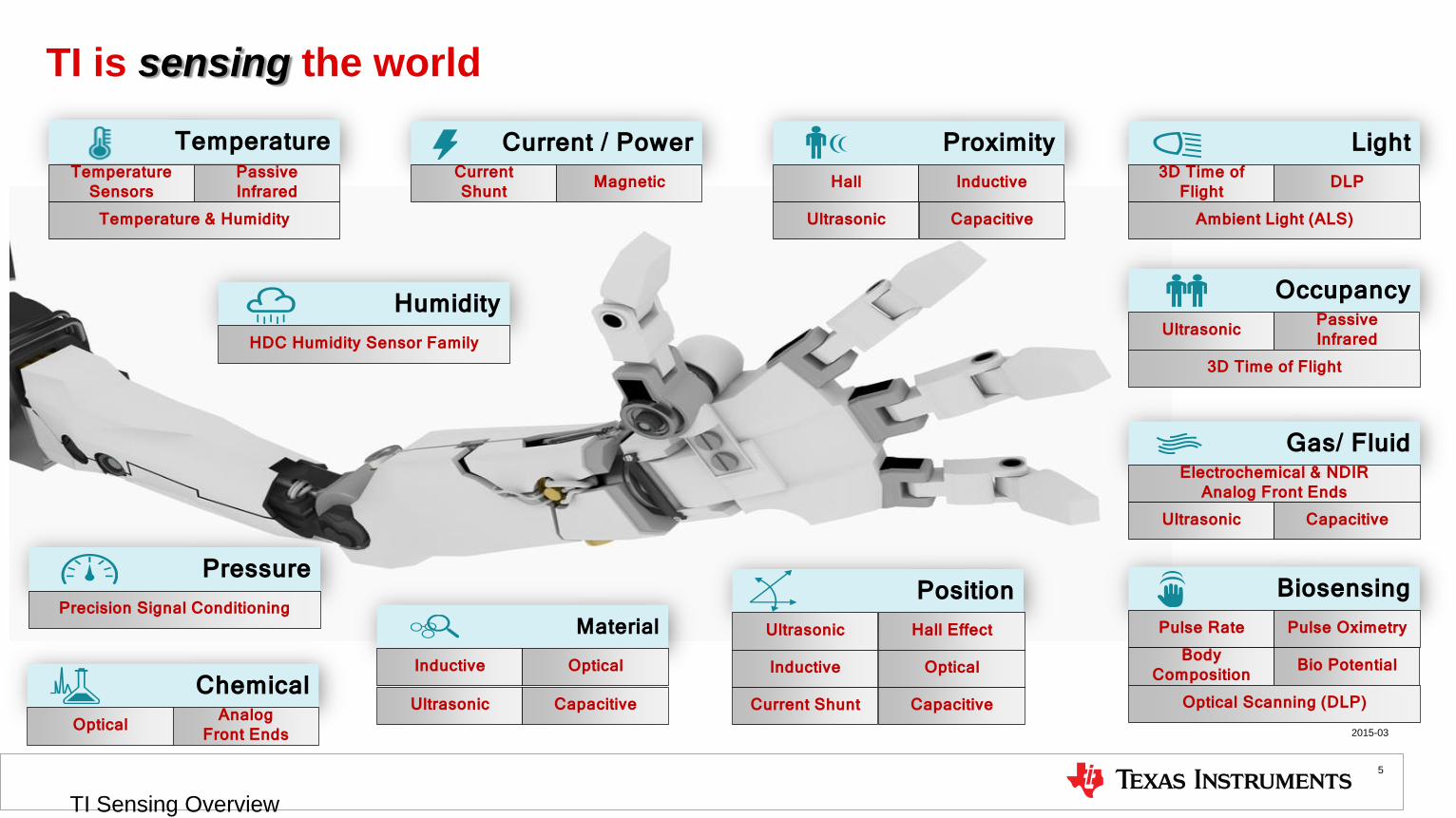
TI is sensing the world
2015-03
TI Sensing Overview
5
Current / Power Current Shunt Magnetic
Material Inductive Optical
Humidity HDC Humidity Sensor Family
Biosensing Pulse Rate Pulse Oximetry
Body Composition Bio Potential
Optical Scanning (DLP) Chemical
Optical Analog Front Ends
Pressure Precision Signal Conditioning
Proximity Hall Inductive
Ultrasonic
Light 3D Time of
Flight DLP
Ambient Light (ALS)
Temperature Temperature
Sensors Passive Infrared
Temperature & Humidity
Occupancy Ultrasonic Passive
Infrared 3D Time of Flight
Capacitive
Gas/ Fluid Electrochemical & NDIR
Analog Front Ends Ultrasonic Capacitive
Position Ultrasonic Hall Effect
Inductive Optical
Current Shunt Capacitive Ultrasonic Capacitive
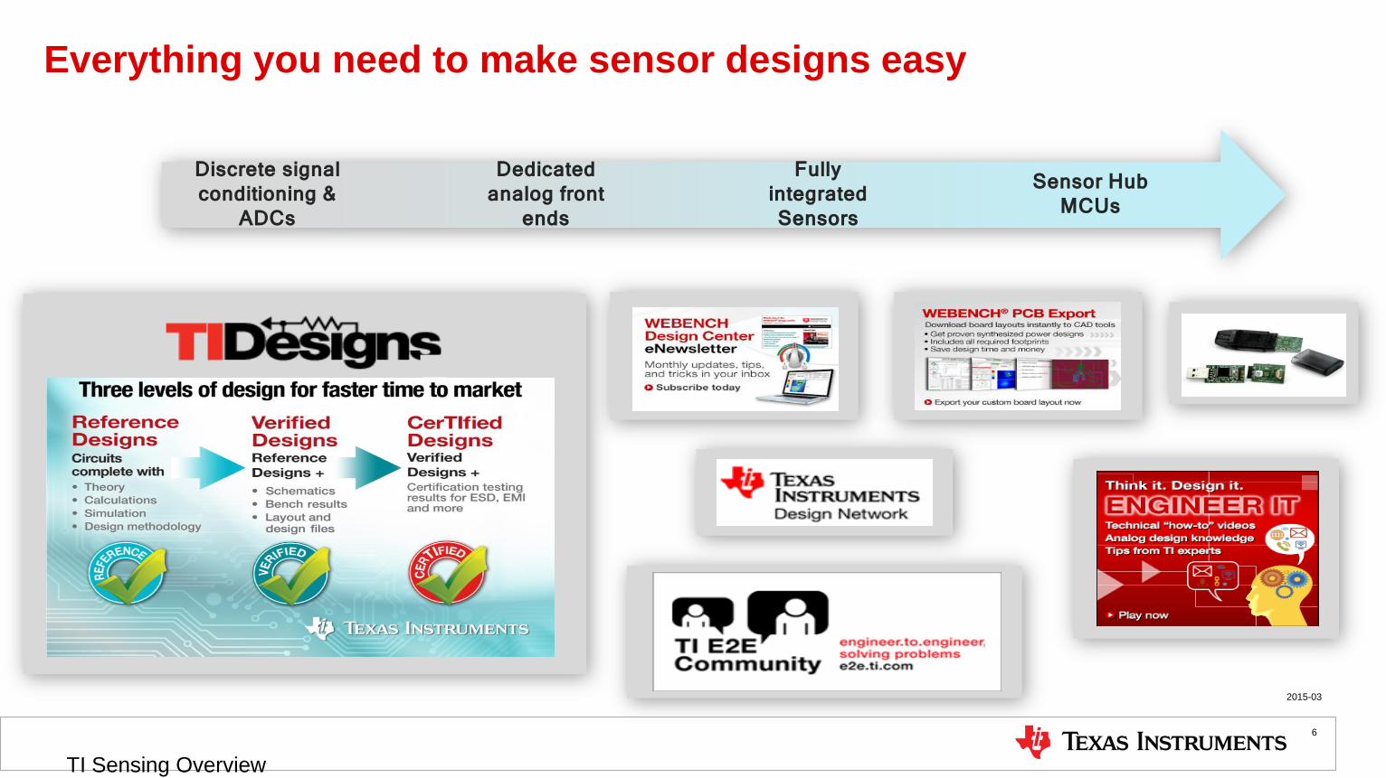
Everything you need to make sensor designs easy
2015-03
TI Sensing Overview
6
Discrete signal conditioning &
ADCs
Dedicated analog front
ends
Fully integrated Sensors
Sensor Hub MCUs

Temperature Sensing

Temperature Sensors
2015-03
TI Sensing Overview
8
IC Temperature Sensing Solutions
Local
TI’s Solutions
• Biggest selection of temp sensor products
• 141 products and counting.
• Industry leader in performance.
• Highest Accuracy : ±0.1’C (LMT70)
• Lowest Power : 1.5µA (TMP103/4)
• Widest Temperature Range : 200’C (LM95172Q)
• Smallest Size: < 0.8mm x 0.8mm (TMP103, LMT70)
• Innovation:
• 1st Fully Integrated Non-Contact Temp Sensor
• Long Haul Cable Interfaces
Benefits of IC Temp Sensors
• Highly Linear
• Guaranteed Accuracy – Zero Calibration
• Programmable Sampling & Alerts
• No Additional Components Needed
• Integration with other functions
• Small Foot Prints
35oC 35oC
65oC
40oC
55oC
Hot
Cold Alert
35oC Obj = 0oC
Example Applications
Cold Chain
Agriculture
Medical Computing Networking
Automotive Automation Metering
Telecom
Non-Contact Thermopiles
Remote
Switch/Thermostat

Comparison of Temperature Sensor Types
Criteria
Temp Sense IC
Thermistor RTD Thermocouple
IR Temp Sensor
Temp
Range -55°C to +150°C -100°C to +500°C -240°C to 700°C -267°C to +2316°C -100°C to +500°C
Accuracy Good Depends on
Calibration Best Good
Depends on
Calibration
Linearity Best Least Better Better Better
Sensitivity Better Best Less Least Less
Circuit
Simplicity Simplest Simpler Complex Complex Simple to Complex
Power Lowest Low High High Medium
Cost $ $-$$$ $$$ $$ $$
2015-03
TI Sensing Overview
9
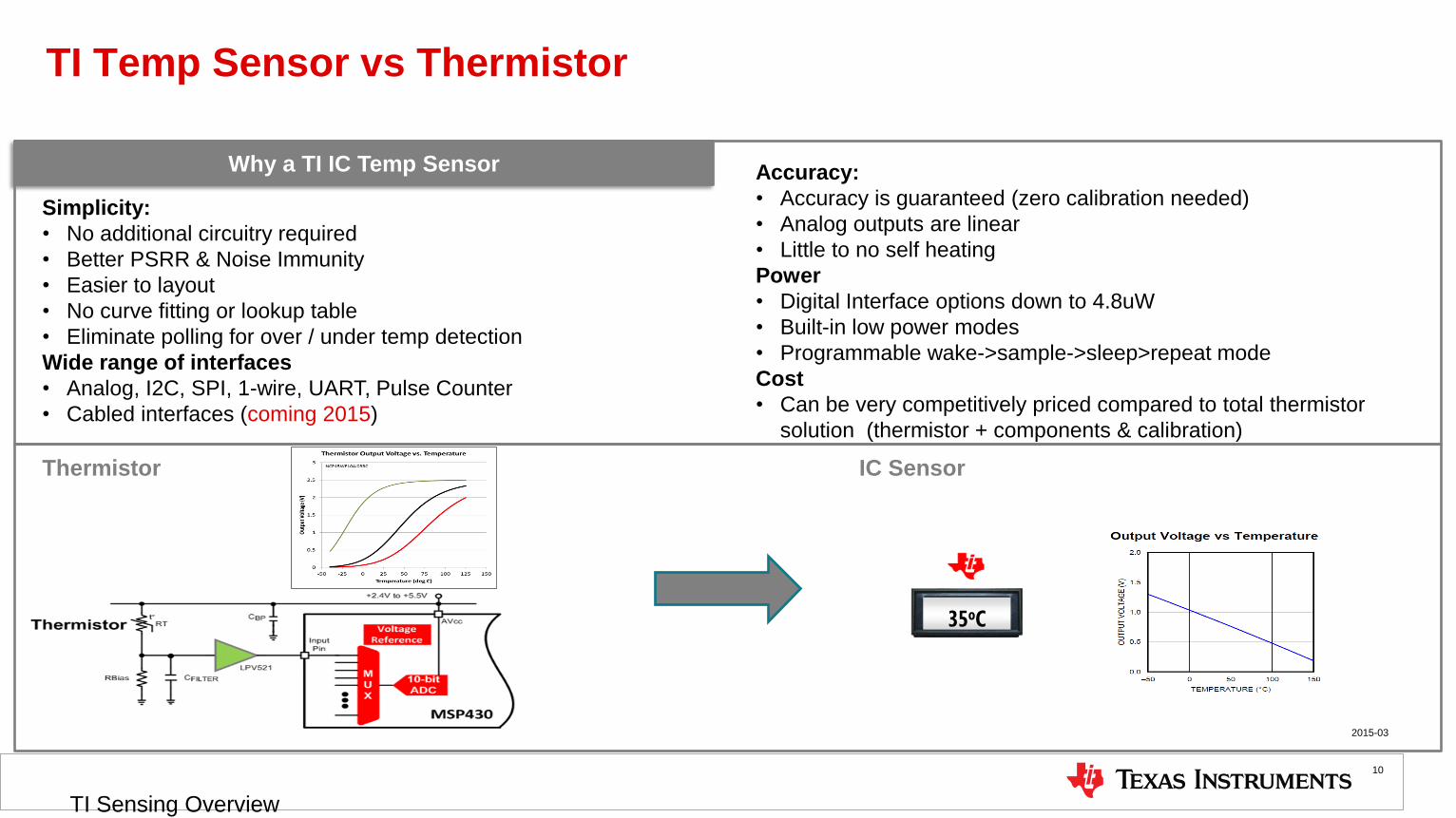
TI Temp Sensor vs Thermistor
10
Why a TI IC Temp Sensor
Simplicity:
• No additional circuitry required
• Better PSRR & Noise Immunity
• Easier to layout
• No curve fitting or lookup table
• Eliminate polling for over / under temp detection
Wide range of interfaces
• Analog, I2C, SPI, 1-wire, UART, Pulse Counter
• Cabled interfaces (coming 2015)
35oC
Thermistor IC Sensor
Accuracy:
• Accuracy is guaranteed (zero calibration needed)
• Analog outputs are linear
• Little to no self heating
Power
• Digital Interface options down to 4.8uW
• Built-in low power modes
• Programmable wake->sample->sleep>repeat mode
Cost
• Can be very competitively priced compared to total thermistor
solution (thermistor + components & calibration)
2015-03
TI Sensing Overview

2-Pin (LMT01)
• High Accuracy
• +/-0.5°C -10°C to 50°C
• +/-1.0°C -20°C to100°C
• Save on wiring costs, shared output return line
• GPIO MCU inputs can be muxed to accommodate more LMT01s per
MCU
• Wide supply range and low power
• Supply: 1.8V to 5.5V
• Quiescent Current: 20μA Max
• Multiple 2-Pin Packages TO-92, TO-126, SMD
Samples (4Q14)
Release (3Q15)
Long Haul / Cabled Temperature Sensors
SMAART Wire ™
• Long distance between nodes (> 3m)
• Up to 32 devices on the chain
• Self-addressing single-wire daisy chain or loop topology
• 3 Conductor or 4 Conductor Cables
• High accuracy (0.5°C max @ 0 - 100°C)
• Supply Range: 1.7V – 5.5V
• Low Power: 60uA (typ)
TMP104: Loop Topology (Released)
TMP107: Bidirectional Daisy Chain(Sampling)
2015-03
TI Sensing Overview
11

Featured Products: Smallest & Lowest Power
TMP103 TMP112 TMP108 LMT70
Interface I2C I2C w/ Alert I2C w/ Window Alert Analog
Supply Range 1.4V to 3.6V 2.5V to 5.5V
I2C Addresses Available 8 8 27
Accuracy:
20°C to +90°C
–20°C to +85°C
–10°C to 100°C
–40°C to +125°C
–55°C to 150°C
2.0°C max
3.0°C max
0.5°C max
3.0°C max
0.75°C max
1.0°C max
0.2°C max
0.36°C max
Resolution 8-Bit 12-Bit -5.18 mV/°C
Quiescent Current (max) 3uA 10 uA 6uA 12uA
Shutdown Current 1uA 50nA
Package Footprint WCSP
0.8x0.8mm
SOT-563
1.6 x 1.6mm
WCSP
1.2x0.8mm
WCSP
0.8x0.8mm
World’s Smallest & Lowest Power
TMP103 • Industry standard I2C/SMBus interface.
• Multiple Device Access mode allows simultaneous communication
with multiple TMP103 Sensors
Ultra-High Accuracy
LMT70 • Highly linear analog output with output enable switch
2015-03
Temp Sensing - Featured Small-Low Power
12

Featured Products: Digital
13
TMP102 TMP112 TMP75(A/B/C) TMP175 TMP275
Interface I2C with Alert
Supply Range 1.4V to 3.6V 2.5V to 5.5V (A)
1.4V to 3.6V (B&C) 2.5V to 5.5V
I2C Addresses Avail. 8 8 27 8
Accuracy:
–25°C to +85°C
–40°C to +125°C
2.0°C max
3.0°C max
0.5°C max
1.0°C max
2.0°C max
3.0°C max
1.5°C max
2.0°C max
0.5°C max
1.0°C max
Resolution 12-Bit
Quiescent Current 10uA
85uA (rev A)
21uA (rev B)
37uA (rev C)
85uA
Shutdown Current 1uA 3uA (rev A)
8uA (rev B & C) 3uA
Package Footprint SOT-563 (1.6mm x 1.6mm) SO-8 (3.0mm x 4.9mm)
MSOP-8 (4.9mm x 6.0mm)
Drop-in Upgrade to any xx75 TMP75 / TMP175 / TMP275 • Lowest Power & Highest Accuracy xx75 sensor available
• Higher accuracy versions available (TMP175 & TMP275)
• 27 address version available (TMP175)
Unbeatable Size & Power TMP102 / TMP112 • Smallest non-CSP Temperature Sensor on the market
• >20x lower power than any competitor
• P2P upgrade from TMP102 to TMP112
Q100 Option
Available
2015-03
TI Sensing Overview
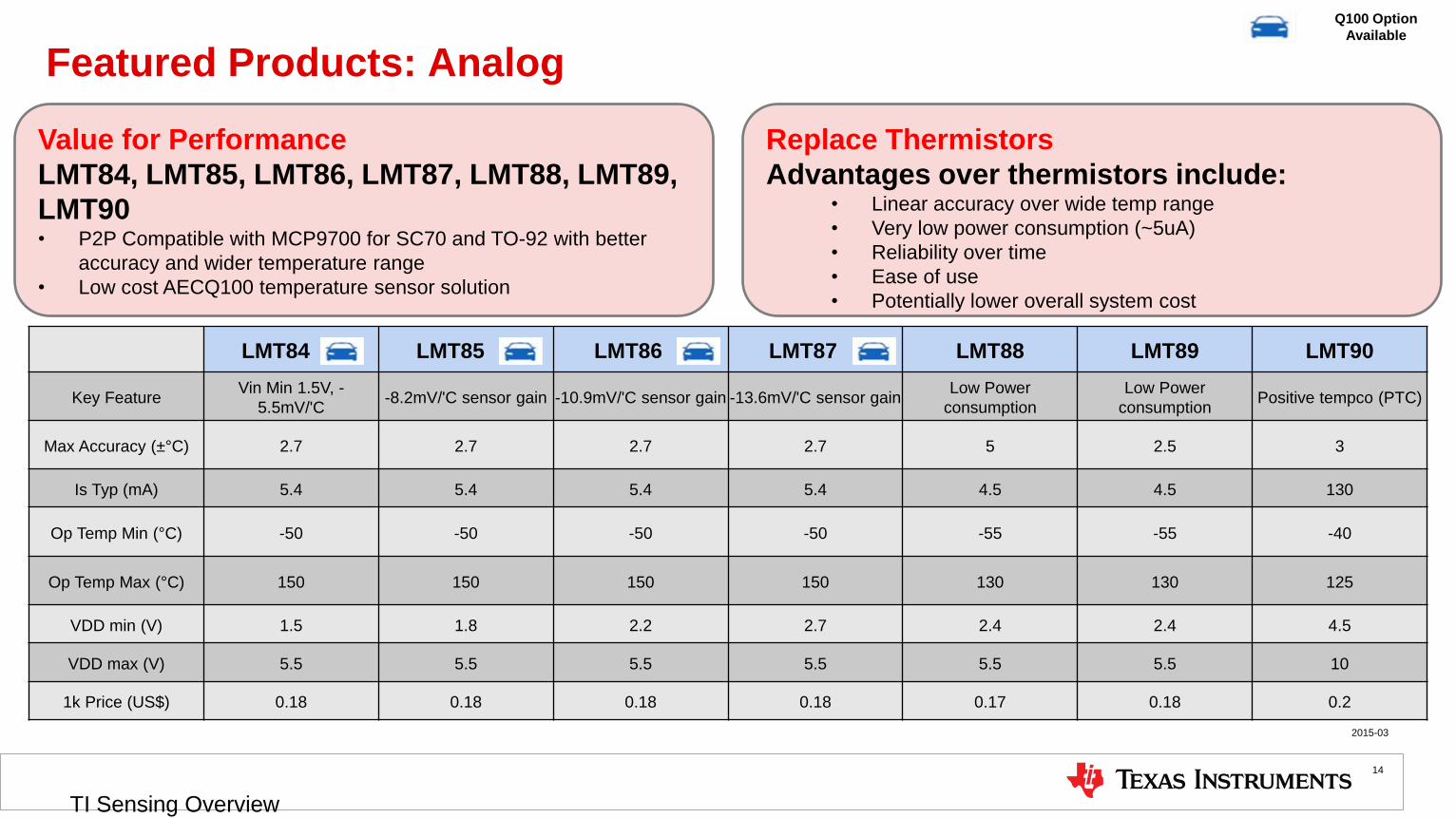
Featured Products: Analog
14
Value for Performance
LMT84, LMT85, LMT86, LMT87, LMT88, LMT89,
LMT90
• P2P Compatible with MCP9700 for SC70 and TO-92 with better
accuracy and wider temperature range
• Low cost AECQ100 temperature sensor solution
Replace Thermistors
Advantages over thermistors include: • Linear accuracy over wide temp range
• Very low power consumption (~5uA)
• Reliability over time
• Ease of use
• Potentially lower overall system cost
LMT84 - LMT85 - LMT86 - LMT87 - LMT88 LMT89 LMT90
Key Feature Vin Min 1.5V, -
5.5mV/'C -8.2mV/'C sensor gain -10.9mV/'C sensor gain -13.6mV/'C sensor gain
Low Power
consumption
Low Power
consumption Positive tempco (PTC)
Max Accuracy (±°C) 2.7 2.7 2.7 2.7 5 2.5 3
Is Typ (mA) 5.4 5.4 5.4 5.4 4.5 4.5 130
Op Temp Min (°C) -50 -50 -50 -50 -55 -55 -40
Op Temp Max (°C) 150 150 150 150 130 130 125
VDD min (V) 1.5 1.8 2.2 2.7 2.4 2.4 4.5
VDD max (V) 5.5 5.5 5.5 5.5 5.5 5.5 10
1k Price (US$) 0.18 0.18 0.18 0.18 0.17 0.18 0.2
Q100 Option
Available
2015-03
TI Sensing Overview
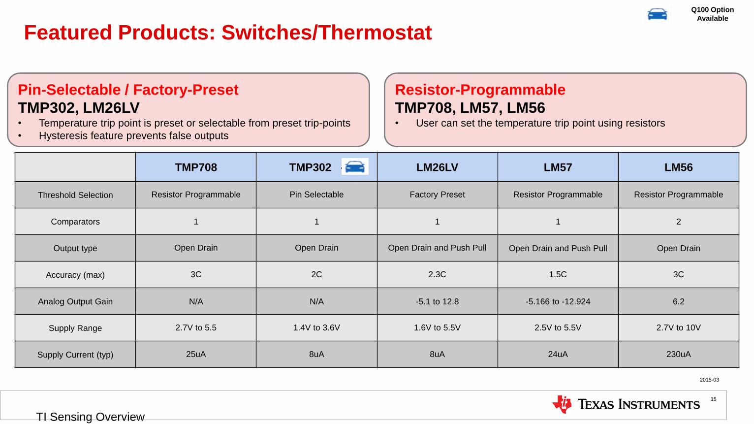
Featured Products: Switches/Thermostat
TMP708 TMP302 - LM26LV LM57 LM56
Threshold Selection Resistor Programmable Pin Selectable Factory Preset Resistor Programmable Resistor Programmable
Comparators 1 1 1 1 2
Output type Open Drain Open Drain Open Drain and Push Pull Open Drain and Push Pull Open Drain
Accuracy (max) 3C 2C 2.3C 1.5C 3C
Analog Output Gain N/A N/A -5.1 to 12.8 -5.166 to -12.924 6.2
Supply Range 2.7V to 5.5 1.4V to 3.6V 1.6V to 5.5V 2.5V to 5.5V 2.7V to 10V
Supply Current (typ) 25uA 8uA 8uA 24uA 230uA
Pin-Selectable / Factory-Preset
TMP302, LM26LV • Temperature trip point is preset or selectable from preset trip-points
• Hysteresis feature prevents false outputs
Resistor-Programmable
TMP708, LM57, LM56 • User can set the temperature trip point using resistors
Q100 Option
Available
2015-03
TI Sensing Overview
15

Featured Products: Non-Contact
TMP006 • Integrated MEMs Thermopile for non-contact temperature
sensing
• Two-Wire Serial Interface :
• Low Power
• Supply 2.2V to 5.5V
• Active Current 270 μA (typ)
• 2-µA shutdown (max)
• Compact package
• 1.9mm x 1.9mm x 0.625mm WCSP
TMP007: • All the features of TMP006 plus…
• Integrated math Engine
• Directly read object temperature
• Programmable Alerts
• Transient Correction
• Nonvolatile memory for storing calibration
2015-03
TI Sensing Overview
16

Featured Products: Remotes
TMP451 TMP435 LM95234 TMP512 / TMP513
# of Remote Channels 1 1 4
TMP512 (2ch)
TMP513 (3ch)
Accuracy (max) +/-1C @ 0C to 70C
+/-2C @ -40C to 125C
+/-1C @ 0C to 100C
+/-2.5C @ -40C to 125C +/-2C @ -40C to 125C
+/-1C @ 15C to 85C
+/-2.5C @ -40C to 125C
Series Resistance Cancellation 1k Ohm 1k Ohm No 3k Ohm
N-Factor Correction Yes Yes No Yes
Auto. Beta Correction No Yes No No
1.8V Capable I2C Yes No No No
Supply Range 1.7V to 3.6V 2.7V to 5.5V 3.0V to 3.6V 3.0V to 26V
Iq (max) 40uA 45uA 800uA 1.4mA
Package MSOP - (3 x 4.9mm)
SOIC - (4.9 x 6mm) MSOP - (3 x 4.9mm) WSON (4 x 4mm)
QFN (4.0 x 4.0mm)
SOIC (9.9 x 6.0mm)
Current Sense Error N/A N/A N/A 1%
Voltage Monitoring Error N/A N/A N/A 1%
1.8V Supply & I2C Voltage
TMP451 • Optimized for advanced processors with only 1.8V communications
Power & Thermal Monitoring
TMP512/TMP513 • Optimized for advanced processors with only 1.8V communications
• Integrated current/voltage/power monitoring
Q100 Option
Available
2015-03
TI Sensing Overview
17

1.8V Capable
Thermal Management Solutions
Local Analog
Local Digital
Contactless IR
Fan Control/ HW Monitors
Switches/ Thermostats
Smallest
LM20 LM94023
Highest Accuracy
LM57
Lowest Power
LM94022 TMP20
Highest Temperature
LMT84
Thermistor Replacement
LMT8x
Measures passive IR to determine object temp without contact
Voltage output proportional to temperature
Highest # of Channels
LM95234 LM95214
Lowest Power
TMP102 TMP103
Highest Temperature
LM95172
Highest Accuracy
TMP275 LM92
TMP112
Industry Standard TMP75 LM75
Reports temperature at location of the sensor
Smallest
TMP112 TMP103
Int. Power Monitor
TMP512 TMP513
Beta Correction
TMP44x LM95245
Most Popular
TMP411 LM96163
Measure any Diode, Transistor, or CPU/GPU/FPGA
Remote Digital
Factory Preset
TMP303 LM27
Pin Programmable
TMP302
Simple hardware over temperature protection
Dual Alerts
LM56 LM57
Resistor Programmable
TMP708 LM57 2 Wire Interface
LM96080 AMC80
Monitor & Control
LMP92001
Fan Control
LM96163 AMC6821
6-channels
comparators LMV7231
LMT9x
Integrated Math
Engine TMP007
TMP451
2015-03
TI Sensing Overview
18
World’s First
TMP006

Tools & Contacts
2015-03
Temp Sensing - Collateral
19
Digital Sample Card
EVMs / Software / Source Code Forums: Temperature Sensor Forum
Articles • NTC thermistors versus voltage output IC temp sensors: ECN,
04/02/13, Brian Gosselin, Jr.
• Signal Chain Basics #79: Digital Temperature Sensors Can Replace
Thermistors: Planet Analog, 07/12/13, Dan Harmon
• Signal Chain Basics #86: Fundamentals of Temp Sensors: Planet
Analog, 07/12/13, Dan Harmon
Remote Temp Sensors: Ideal for Industrial Implementations:
Electronic Design, 01/26/15, Dan Harmon
Videos: • Engineer-It: NTC vs analog temp sensors
• Winning by Design video
• Thermal Management Summary
• Selling Against Thermistors
• LMT84-LMT90 1-pagers
• Using the Bar Chart
Analog Sensor Selection Wheel

Humidity Sensing (HDC)

Fully Integrated Humidity Sensor
Humidity Sensing
2015-03
TI Sensing Overview
21
Humidity Sensing Solutions
Target:
Humidity
Polyimide
Layer
Target Applications
Thermostat
HVAC control
Refrigerator
Freezer
Printers
Mobile devices
Automotive
Cargo shipping
Wearable devices
TI’s Humidity Sensors
HDC1000(8): High-accuracy humidity sensor
Features: 2x1.6mm footprint
+/-3% (+/-4%) humidity accuracy
0.2-degC temperature accuracy
Low current (1.2uA @ 1sps)
Capacitance-
to-digital
Temp
sensor
Sensor Humidity sensor
Tools & Support
• TI Designs:
• Wireless humidity sensing node (coming soon)
• Humidity sensing E2E forum
• Product evaluation board
Benefits of TI’s Humidity Sensors
• Low-current solution
• Unique sensor placement robust against dirt and dust
• High-resolution integrated temperature sensor
• Smallest size solution
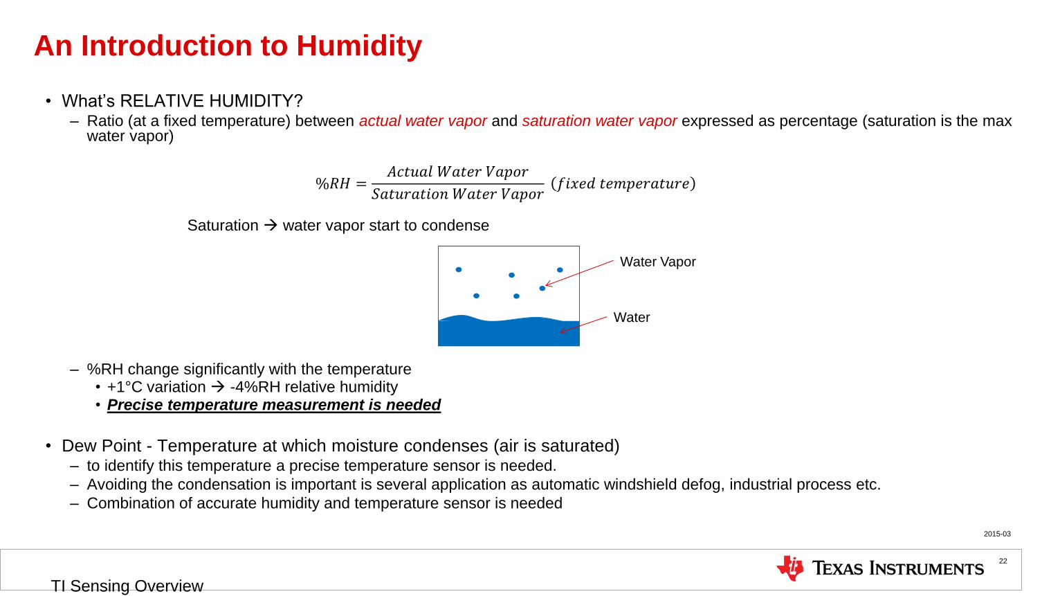
An Introduction to Humidity
• What’s RELATIVE HUMIDITY? – Ratio (at a fixed temperature) between actual water vapor and saturation water vapor expressed as percentage (saturation is the max
water vapor)
%𝑅𝐻 =𝐴𝑐𝑡𝑢𝑎𝑙 𝑊𝑎𝑡𝑒𝑟 𝑉𝑎𝑝𝑜𝑟
𝑆𝑎𝑡𝑢𝑟𝑎𝑡𝑖𝑜𝑛 𝑊𝑎𝑡𝑒𝑟 𝑉𝑎𝑝𝑜𝑟 𝑓𝑖𝑥𝑒𝑑 𝑡𝑒𝑚𝑝𝑒𝑟𝑎𝑡𝑢𝑟𝑒
Saturation water vapor start to condense
– %RH change significantly with the temperature • +1°C variation -4%RH relative humidity • Precise temperature measurement is needed
• Dew Point - Temperature at which moisture condenses (air is saturated) – to identify this temperature a precise temperature sensor is needed.
– Avoiding the condensation is important is several application as automatic windshield defog, industrial process etc.
– Combination of accurate humidity and temperature sensor is needed
Water
Water Vapor
2015-03
TI Sensing Overview
22

TI’s Humidity Sensing Solution
2015-03
TI Sensing Overview
23
Moisture
Sen
sin
g
Ele
men
t
Devic
e
Blo
ck
Dia
gra
m
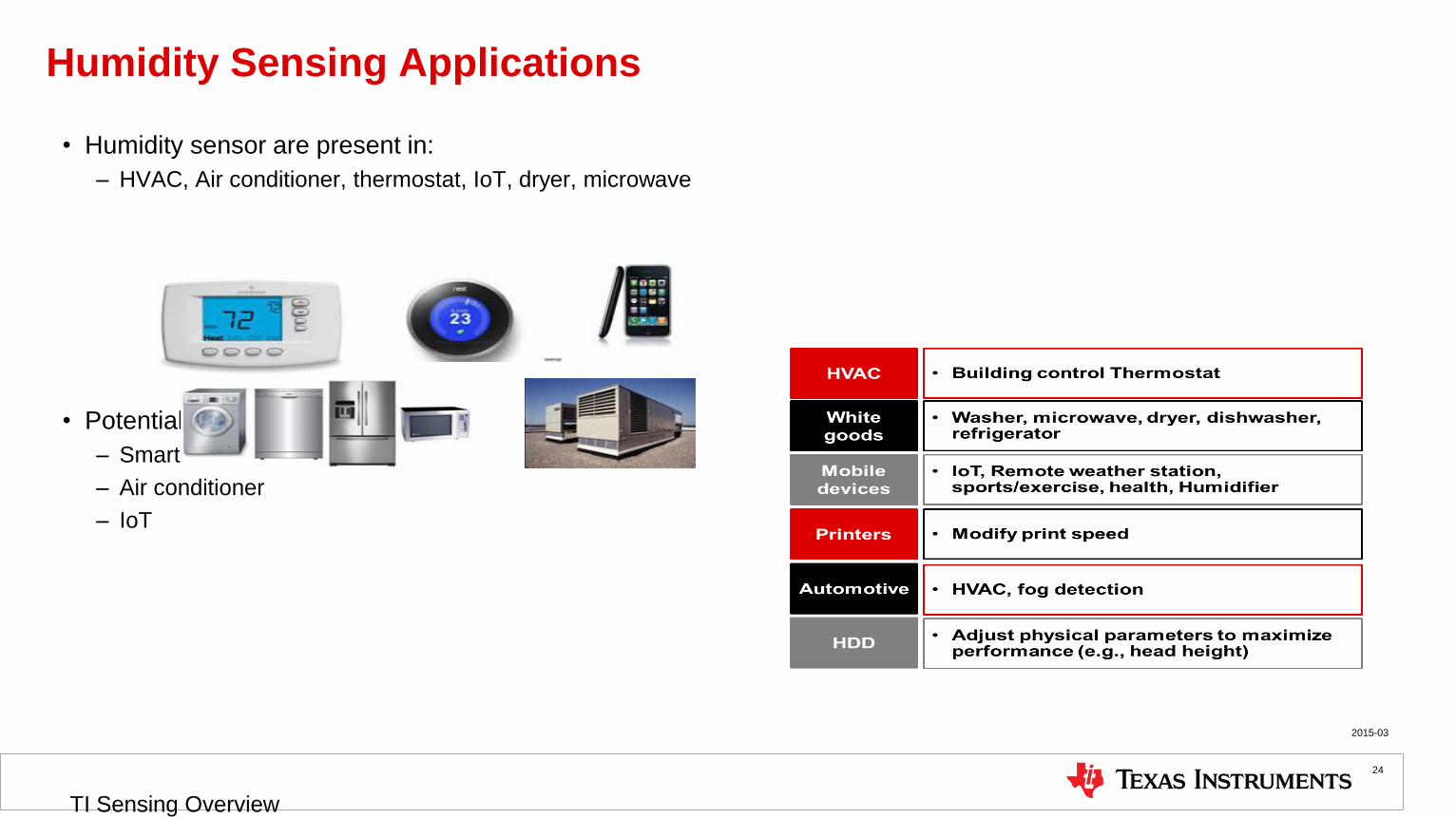
Humidity Sensing Applications
• Humidity sensor are present in:
– HVAC, Air conditioner, thermostat, IoT, dryer, microwave
• Potential Customers
– Smart thermostat maker
– Air conditioner
– IoT
2015-03
TI Sensing Overview
24

HDC1000/8: Low-power, dust-resistant humidity and temperature sensor
• Lowest current: – 1.2uA avg. for humidity and temp @ 1sps
– 820nA avg. for humidity only @ 1sps
• Smallest size: – Tiny 2mm x 1.6mm footprint
• High accuracy: – ± 3%/± 4% relative humidity accuracy
– ±0.2degC temperature accuracy
• Multiple applications – HVAC
– Smart thermostats and room monitors
– White goods
– Printers
– Medical devices
– Shipping & inventory
– Mobile devices
– Wearable devices
– Handheld meters
– Window defog
25

SSP Humidity sensor roadmap
Legend
RH
Accu
racy
Lo
w (
+/-
4%
)
Mid
(+
/-3
%)
HDC1000
2.7-5.5V
WCSP-8
HDC1050
2.7-5.5V
DFN-6
Definition Sampling Planned Concept Production
HDC2080
1.7-3.6V
DFN-6
3x3mm
HDC1080/Q
2.7-5.5V
DFN-6
Hig
h (
+/-
2%
)
HDC3000
1.7-3.6V
WCSP-8
1.5x1.5mm
HDC1008
2.7-5.5V
WCSP-8
New Polyimide
direct replacement
2015 2016 2017
HDC1002
2.7-5.5V
WCSP-8
3x3mm 1.6x2.04mm NDA Material
Please contact TI
HDC1080 Improved high humidity and temperature stability
• HDC1080 is a new device based on the HDC1050 silicon and new sensing element chemical compound (polyimide)
• HDC1080 improved the high humidity and high temperature stability
• HDC1080 target accuracy: 2%RH (typ.)
27
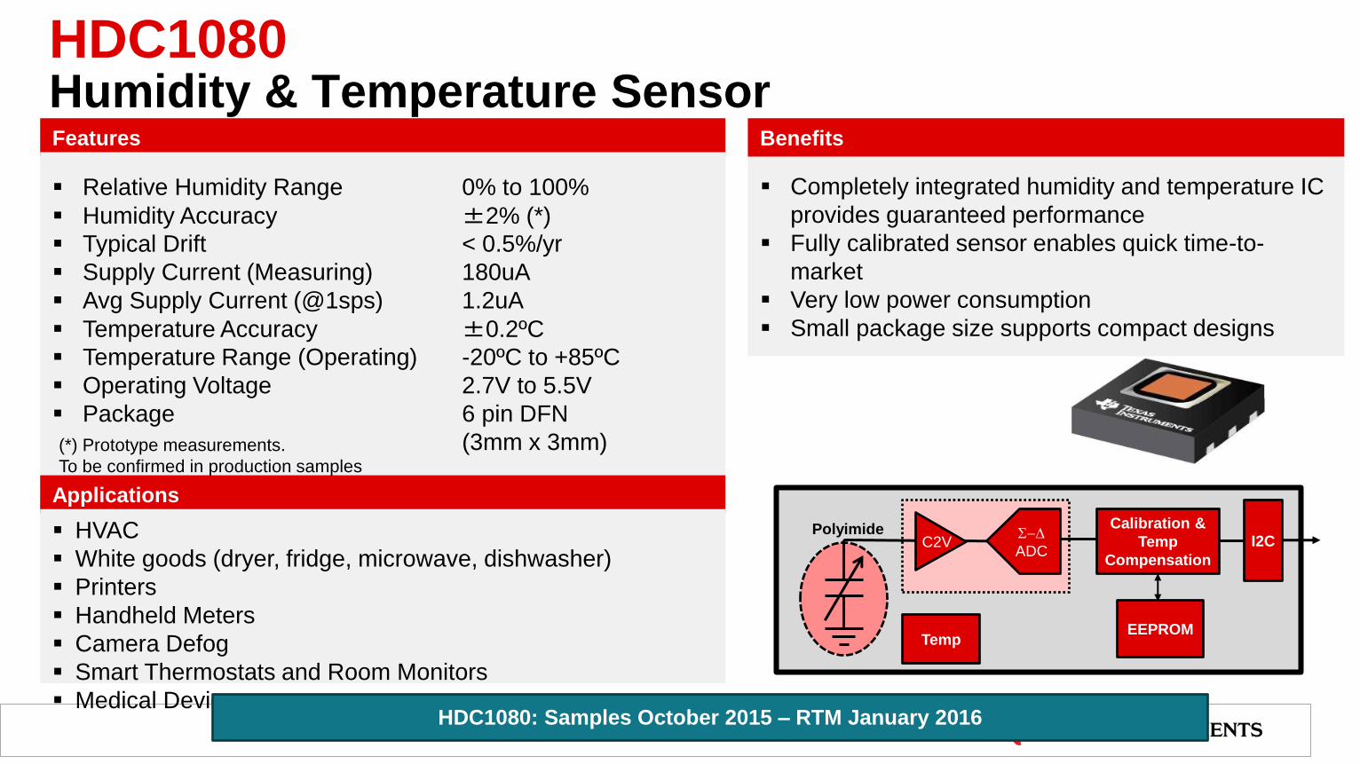
Completely integrated humidity and temperature IC
provides guaranteed performance
Fully calibrated sensor enables quick time-to-
market
Very low power consumption
Small package size supports compact designs
Applications
HVAC
White goods (dryer, fridge, microwave, dishwasher)
Printers
Handheld Meters
Camera Defog
Smart Thermostats and Room Monitors
Medical Devices
Features Benefits
HDC1080 Humidity & Temperature Sensor
Relative Humidity Range 0% to 100%
Humidity Accuracy ±2% (*)
Typical Drift < 0.5%/yr
Supply Current (Measuring) 180uA
Avg Supply Current (@1sps) 1.2uA
Temperature Accuracy ±0.2ºC
Temperature Range (Operating) -20ºC to +85ºC
Operating Voltage 2.7V to 5.5V
Package 6 pin DFN
(3mm x 3mm)
I2C
Calibration &
Temp
Compensation
S-D
ADC
Temp
C2V
EEPROM
Polyimide
(*) Prototype measurements.
To be confirmed in production samples
HDC1080: Samples October 2015 – RTM January 2016

Wide supply range for battery power application
without LDO/Boost Converter
Very low power consumption
Integrated humidity and temperature sensor for
compact application
Applications
Smart Thermostats and Room Monitors
IoT
HVAC
White goods (dryer, fridge, microwave, dishwasher)
Printers
Features Benefits
HDC2080 Humidity & Temperature Sensor
Relative Humidity Range 0% to 100%
Humidity Accuracy ±2%(*)
Supply Current (Measuring) 180uA
Avg Supply Current (@1sps) 0.7uA
Temperature Accuracy ±0.2ºC
Programmable Data Rate
On Demand, 5Hz, 2Hz, 1Hz, 0.5Hz, 0.2Hz, 0.1Hz, 1/60Hz,
1/120Hz
Programmable thresholds and interrupt
Temperature Range (Operating) -20ºC to +85ºC
Operating Voltage 1.7V to 3.6V
Package 6 pin DFN (3mm x 3mm)
I2C
Calibration &
Temp
Compensation
S-D
ADC
Temp
C2V
EEPROM
Polyimide
Int.
Gen
HDC2080: Samples Q2’16 – RTM Q3’16
(*) Prototype measurements.
To be confirmed in production samples
NDA Material
Please contact TI

Enhanced digital features (1)
• Output configuration
– Automatic ODR (Output Data Rate)
On Demand, 5Hz, 2Hz, 1Hz, 0.5Hz,
0.2Hz, 0.1Hz, 1/60Hz, 1/120Hz
• Threshold - Alarm
– High threshold value
– Low threshold value
• Interrupts
– Dataready/Interrupt bit and output signal
• Interrupt are triggered by
Humidity and/or Temperature
30
Interrupt
H+T H+T H+T
Selectable Output data rate
H/T

Programmable “comfort zone”
• Programmable thresholds enable to define a “comfort zone” where environmental humidity and temperature are
within the wanted limits
• HDC2080 autonomously monitors the ambient and signal is the environmental condition are outside the programmed
thresholds
31
H
T
Interrupt
Comfort zone

Digital features (2)
• User Temperature programmable offset
• User Humidity programmable offset
Humidity output +
User Humidity offset
From compensation
Algorithm
Temperature output +
User Temperature offset
From compensation
Algorithm
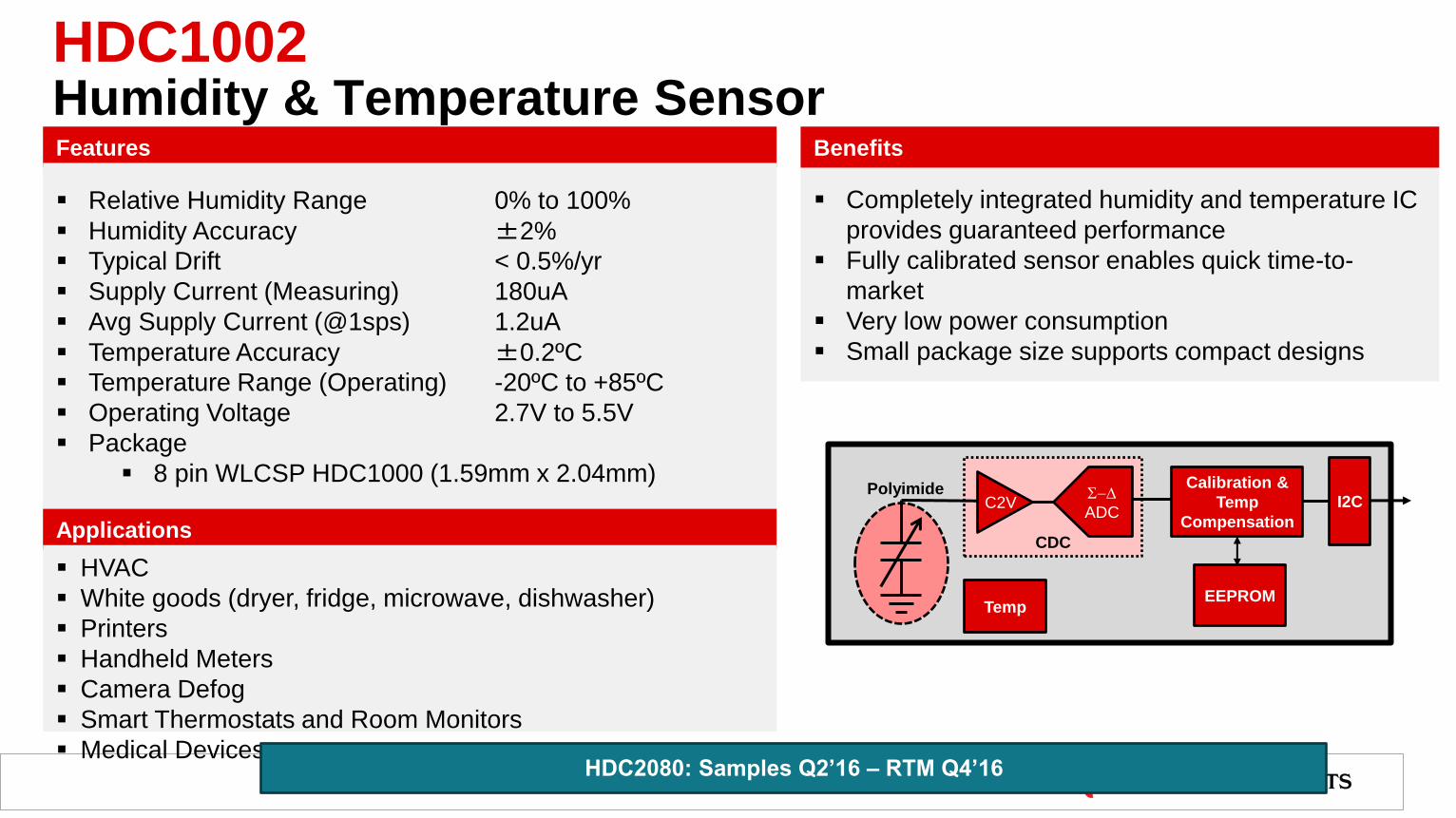
Completely integrated humidity and temperature IC
provides guaranteed performance
Fully calibrated sensor enables quick time-to-
market
Very low power consumption
Small package size supports compact designs
Applications
HVAC
White goods (dryer, fridge, microwave, dishwasher)
Printers
Handheld Meters
Camera Defog
Smart Thermostats and Room Monitors
Medical Devices
Features Benefits
HDC1002 Humidity & Temperature Sensor
Relative Humidity Range 0% to 100%
Humidity Accuracy ±2%
Typical Drift < 0.5%/yr
Supply Current (Measuring) 180uA
Avg Supply Current (@1sps) 1.2uA
Temperature Accuracy ±0.2ºC
Temperature Range (Operating) -20ºC to +85ºC
Operating Voltage 2.7V to 5.5V
Package
8 pin WLCSP HDC1000 (1.59mm x 2.04mm)
CDC
I2C
Calibration &
Temp
Compensation
S-D
ADC
Temp
C2V
EEPROM
Polyimide
HDC2080: Samples Q2’16 – RTM Q4’16

HDC100x/HDC3000 intrinsic dust resistant
• Dust falls on top of the sensing element reducing the performances until the complete blockage of the sensor
• Some competitors suggest to cover the sensor with a filter/grid (very expensive more than the device itself)
• HDC100x/HDC3000 has the sensing element on the bottom part of the sensor.
• Sensing element is intrinsically protect from the dust that falls on the top part
Humidity sensor
Sensing Element
Polyimide
Dust
Classical solution in DFN package
Polyimide PCB
CSP Die
Humidity / Moisture
Dust
HDC100x intrinsic dust resistant structure

HDC3000 smallest humidity sensor
• Smallest humidity sensor in the market
• Improved temperature compensation algorithm
• Enhanced digital features (same of HDC2080)
35
HDC3000
1.5mm
1.5mm
Polyimide PCB
CSP Die Humidity / Moisture
Dust
NDA Material
Please contact TI

Wide supply range for battery power application
without LDO/Boost Converter
Very low power consumption
Integrated humidity and temperature sensor for
compact application
Applications
Smart Thermostats and Room Monitors
IoT
HVAC
White goods (dryer, fridge, microwave, dishwasher)
Printers
Features Benefits
HDC3000 Humidity & Temperature Sensor
Relative Humidity Range 0% to 100%
Humidity Accuracy ±2%(*)
Supply Current (Measuring) 300uA
Avg Supply Current (@1sps) 0.7uA
Temperature Accuracy ±0.2ºC
Programmable Data Rate
On Demand, 5Hz, 2Hz, 1Hz, 0.5Hz, 0.2Hz, 0.1Hz,
1/60Hz, 1/120Hz
Programmable thresholds and interrupt
Operating Voltage 1.7V to 3.6V
Package 6 pin WLCSP (1.5mm x 1.5mm)
I2C
Calibration &
Temp
Compensation
S-D
ADC
Temp
C2V
EEPROM
Polyimide
Int.
Gen
(*) Prototype measurements.
To be confirmed in production samples
HDC2080: Samples Q4’16 – RTM Q1’17
NDA Material
Please contact TI

Current / Power Monitoring

Current Sensing
Current Shunt Solutions
TI Offers:
• High side & Low side current shunt monitors
• Analog & Digital interfaces
• Complete Powering Monitoring (I, V, P)
• Range of products supporting a common modes from -
16V up to +80V
• Parts supporting 1.8V supply
TI Advantage
• Accuracy: Industry leading parts offsets as low as +/-10uV (max)
• Integration: Largest selection of digital power monitors & overcurrent protection
• Lowest Power: As low as 54uW Iq • Size: The smallest leaded & CSP packages in the
market • Price Competitive
Example Applications
Automotive Telecom Networking /
Computing Metering
Automotive Telecom Networking /
Computing Metering
LOAD
-
+
Power
Supply
High-Side
Sensing
-
+Low-Side
Sensing
VOUT
VOUT
2015-03
TI Sensing Overview
38
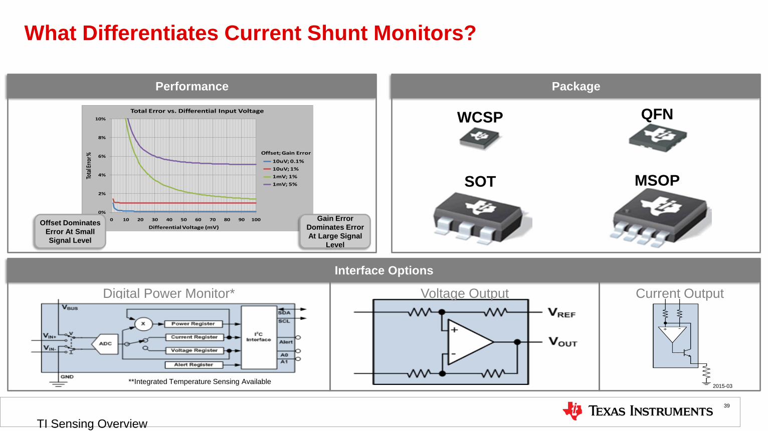
What Differentiates Current Shunt Monitors?
2015-03
TI Sensing Overview
39
Performance Package
Interface Options
Digital Power Monitor*
0%
2%
4%
6%
8%
10%
0 10 20 30 40 50 60 70 80 90 100
Tota
l Err
or %
Differential Voltage (mV)
Total Error vs. Differential Input Voltage
10uV; 0.1%
10uV; 1%
1mV; 1%
1mV; 5%
Offset; Gain Error
Gain Error
Dominates Error
At Large Signal
Level
Offset Dominates
Error At Small
Signal Level
**Integrated Temperature Sensing Available
WCSP
SOT
QFN
MSOP
Voltage Output Current Output

Featured Current Sense Products
40
INA300 INA226 INA210 INA282
Interface Comparator I2C with Alert Analog Analog
Supply Range 2.7V to 5.5V 2.7V to 5.5V 2.7V to 5.5V 2.5V to 18V
Common Mode Range 0V to 36V 0V to 26V -0.3V to 26V -16V to 80V
Accuracy (max) 500uV Offset Error 10uV Offset Error
0.1% Gain Error
35uV Offset Error
1% Gain Error
70uV Offset Error
1.4% Gain Error
Resolution 16-Bit N/A N/A
Quiescent Current (Max) 150uA 420uA 100uA 900uA
Package QFN-10 MSOP-10
3.0mm x 4.9mm
SC70 (2mm x 2.1mm)
QFN (1.3mm x 1.8mm)
SOIC
4.9mm x 6mm
Bidirectional Zero-Drift
INA210-215 • Affordable Accuracy
• 140dB CMRR
• Low Power
Industry Leading Accuracy & Integration
INA226 • Reports Current, Voltage, and Power
• Programmable sampling
• Programmable Alert
• Enable’s smallest Rsense
Precision High Voltage
INA282-286 • Industry leading accuracy at high voltages
• Unbeatable 140dB CMRR
Programmable Over-Current Detection
INA300 • Single Resistor to Program Threshold
• Selectable Response Time (10us, 50us, or 100us)
• Selectable Hysteresis (2mV, 4mV, 8mV)
• Open Drain Output with optional Latch Mode.
Q100 Option
Available
2015-03
TI Sensing Overview

Featured Current Sense Products
41
LMP8480 LMP8481 MAX4080/MAX4081
Topology Unidirectional Bidirectional Uni / Bi
VOS (typ) mV 0.08 0.08 0.1
VOS (Max) mV 0.9 0.9 1.2
CMVR V 4.0 to 76 4.0 to 76 4.5 to 76
Gain Error Over Temp % 0.8 0.8 1.2
Gains Available V/V 20, 50, 60 & 100 20, 50, 60 & 100 5, 20 & 60
Bandwidth kHz 270 270 150
Supply Current uA 155 155 190
Supply Voltage V 4.5 to 76 4.5 to 76 4.5 to 76
Package MSOP8/(QFN8) MSOP8/(QFN8) SIOC8/MSOP8
High Voltage and High Precision: Drop-in Upgrade to Maxim’s MAX4080/4081
LMP8480/LMP8481 • Wide CMVR with wide supply voltage range current • Lower Vos and Gain error improves system
sense amplifier accuracy
• Excellent combination of low offset and wide BW • Wider bandwidth preserves waveform fidelity
• P2P upgrade to MAX4080/MAX4081 and allows wider use
• Wider CMVR
2015-03
TI Sensing Overview

Current Shunt Management Solutions
Smallest
INA231
Lowest Offset
INA226
Lowest Power
INA226 INA3221
Triple Channel
INA3221
I2C/SMBus interface
Lowest Power LMP8480 LMP8481
Highest CMVR INA282 family
Lowest Offset INA282 family
Programmable Gain LMP8645HV LMP8646
Smallest INA193 family
Lowest Power INA216
Smallest INA216
Lowest Offset INA210 family Smallest
INA168
Lowest Power INA168
Lowest Offset INA139
Programmable Alerts
INA230 INA226 INA3221 INA231
Programmable Gain
INA223 LMP8645
Digital Output
Analog Voltage Output
Vcm>60V
Over– current
Protection (OCP)
Analog Current Output
Vcm<60V
Analog Voltage Output
Vcm<60V
Integrated Shunt
Resistor
2mΩ Voltage Output INA250
Over-Current Protection
INA300 INA200 family
Fastest/Widest BW
LMP92064
Widest BW LMP8640
Widest BW INA193 fam. INA200 fam.
INA225 2015-03
TI Sensing Overview
42

Isolated Current Sensing Methods
43
Open-loop
Isolated shunt solutions
10A 100A 1000A
10 %
1%
0.1
%
ME
AS
UR
EM
EN
T A
CC
UR
AC
Y
Closed-loop Hall-effect
Closed-loop Fluxgate sensors
Bus-bar In Package
PRIMARY CURRENT
TI parts offer a complete coverage of the isolated current measurement space
DRV411 Hall sensor
Signal Conditioning IC
AMC1xxx ISO12x Isolated DS Modulators Isolated Amplifiers
2x DRV425 IFG Magnetic Sensor+ Signal Conditioning IC
DRV401/42x IFG Magnetic Sensor +
Signal Conditioning IC
DRV425 IFG Magnetic Sensor+ Signal Conditioning IC

DRV425 Current Sense IC with Integrated Magnetic Sensor and Readout
44
• High sensor sensitivity (100x hall sensors), low offset and
drift
• Sensor integration for small size and lower system cost and
better EM robustness
• Unique sensor feedback loop enables exceptional linearity
and gain accuracy
• Gain / range adjustable by a single resistor
• Fast detection and indication of input and overload
conditions
Benefits Features
Applications
• Current monitoring
• Magnetic field sensing
• Magnetic field gradient sensing
• Precision Integrated Magnetic Sensor: 2µT
Offset, 5nT/C Drift (typ)
• Adjustable Sensor Range: up to ±2mT
• High Gain Accuracy: 0.3%,5ppm/C (max)
• Wide Signal Bandwidth: 47 kHz (typ)
• Precision Reference: 50 ppm/C (max)
• Over-Range and Error Flags
• Power Supply 3 V to 5.5 V
• Temperature Range: -40 to +125C
• Packages: 4x4mm QFN
Current
Conductor
Integrator / Filter
Sensor
ReadoutH-Bridge
Driver
1.65 V or 2.5 V
Voltage ReferenceDevice Control & Degaussing
VOUT
REFIN
RSEL0 RSEL1
VDD GND COIL1 COIL2 AINP AINN
OR ERROR DEMAG GSEL0 GSEL1
COMP1 COMP2
Magnetic
Sensor
Internal
Compensation
Coil
Magnetic
Field
DRV425
Rshunt
IM
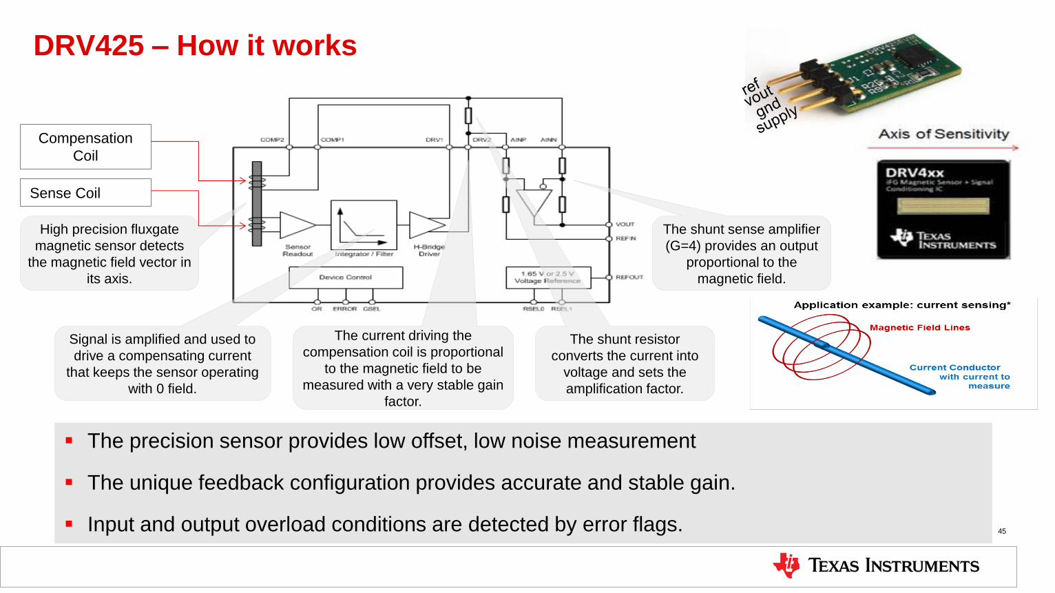
DRV425 – How it works
45
High precision fluxgate
magnetic sensor detects
the magnetic field vector in
its axis.
Signal is amplified and used to
drive a compensating current
that keeps the sensor operating
with 0 field.
The current driving the
compensation coil is proportional
to the magnetic field to be
measured with a very stable gain
factor.
The shunt resistor
converts the current into
voltage and sets the
amplification factor.
The shunt sense amplifier
(G=4) provides an output
proportional to the
magnetic field.
The precision sensor provides low offset, low noise measurement
The unique feedback configuration provides accurate and stable gain.
Input and output overload conditions are detected by error flags.
Compensation
Coil
Sense Coil

Magnetic Field inside Bus Bar Hole
46
Field gradient inside the hole is proportional to the current
through busbar
The gradient is measured by two DRV425 sensors on the
opposite sides of a PCB
Common mode fields are rejected

DRV425 - Value for High-Current Measurements
47
Sensor integrated into the BusBar for isolated measurement up to 1000s of Amps
Differential measurement inside the bus bar further increases immunity to stray fields and to frequency effects and to overcurrent
conditions
Lower power than shunt based solutions
Compact module design and ease of installation
High SNR by replacing discrete hall sensors
High accuracy over a wide dynamic range
Lower complexity and single temperature calibration
Benefits
New approach Today

Collateral
48
Forums: Current Shunt E2E Forum
Articles: • EE Times 4 Part Series by Pete Semig & Colin Wells
– Current Sensing Fundamentals
– Current Sensing Devices
– Current Sensing Accuracy
– Current Sensing Layout & Troubleshooting
• Use Current Measurement As A Leading Indicator For System Thermal
Management: Electronic Design, 02/14/14, Dan Harmon
• Prevent System Damage Via Fast, Accurate Over-Current Detection:
Electronic Design, 05/14/14, Dan Harmon
• Signal Chain Basics #93: How to Maximize Low-Side Sensing
Performance: Planet Analog, 09/05/14, Dan Harmon
• Signal Chain Basics #100: Rethinking system level management with
subsystem over-current detection and monitoring, Planet Analog,
03/24/15, Dan Harmon
Videos: • Introduction to optimized over-current detector INA300
• Engineer It-How to simplify high voltage current measurement
• Current Sensing: Low Side, High Side, and Zero Drift
2015-03 TI Sensing Overview

Inductive Sensing (LDC)

Inductive Sensing
Inductive Sensing Solutions
Target Applications
Switches
Knobs
Buttons
Keypads
Encoders
Rotation sensing
Lateral sensing
Metal detection
Metal identification
Gear counting
TI’s Inductance-to-Digital Converters
New LDCs: Multi-channel, easy-to-use
LDC1312/4: 2-/4-ch, 3.3-V, 12-bit LDC
LDC1612/4: 2-/4-ch, 3.3-V, 28-bit LDC
LDC1000: 1-ch, 24-bit L / 16-bit Rp LDC
LDC1041: 1-ch, 24-bit L / 8-bit Rp LDC
LDC1051: 1-ch, 8-bit Rp LDC
Tools & Support
• TI Designs:
• Distance & Weight Msmt (TIDA-00215)
• Keypad (Q1, 2015)
• 2-degree knob (Q1, 2015)
• Touch-on-metal buttons (Q1, 2015)
• Inductive sensing E2E forum
Benefits of Inductive Sensing
• Does not require magnets
• Reliable by virtue of being contactless
• Insensitive to dust, dirt, water, and oil
• Sub-micron resolution
• Sensor is low-cost
• Allows for remote sensing
NEW Target
LDC chip PCB coil
Wire-wound coil
Discrete inductor
Spring
Conductor
Inductance–to–digital
2015-03
TI Sensing Overview
50

Advantages of Inductive Sensing:
Does not require magnets
Reliable by virtue of being contactless
Insensitive to environmental contaminants (dust, dirt, etc.)
Sub-micron resolution
Sensor is low-cost
Electronics can be located remotely from the sensor
LDC Enables Inductive Sensing
51
Conductive
target
Wire wound sensor coil Axial / Lateral / Angular motion of target
Ind
ucti
ve
se
ns
ing
LDCINDUCTANCE TO DIGITALCONVERTER
Be
ne
fits
Conductive
target
Spring as a sensor Extension / Compression / Twist of the spring
PCB Sensor coil Axial / Lateral / Angular motion of target
2015-03
TI Sensing Overview
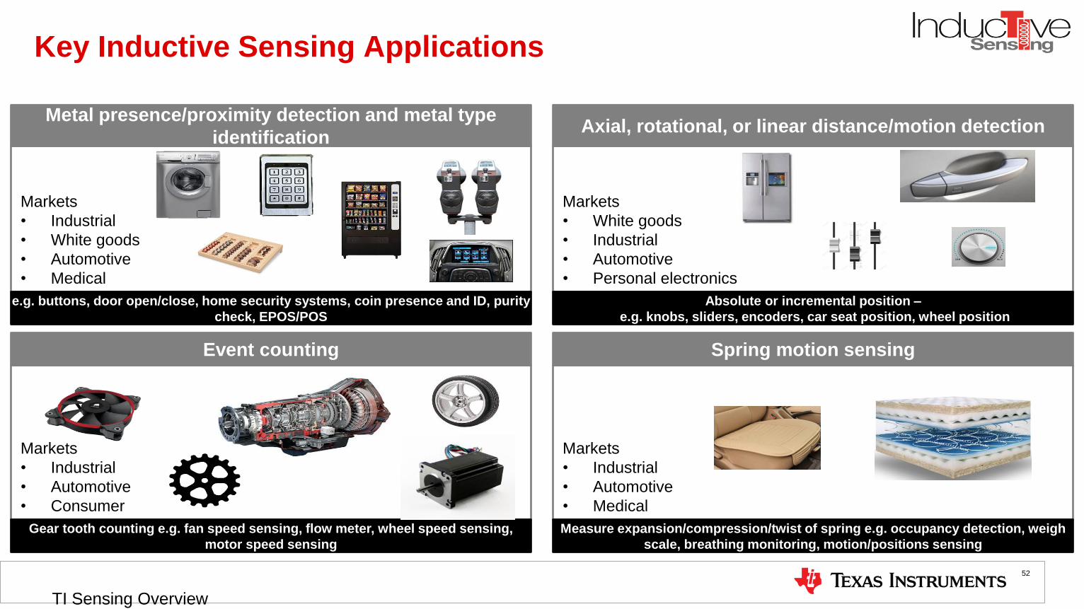
Key Inductive Sensing Applications
52
Markets
• Industrial
• White goods
• Automotive
• Medical
Markets
• White goods
• Industrial
• Automotive
• Personal electronics
Markets
• Industrial
• Automotive
• Consumer
Markets
• Industrial
• Automotive
• Medical
Metal presence/proximity detection and metal type
identification
Absolute or incremental position –
e.g. knobs, sliders, encoders, car seat position, wheel position
Axial, rotational, or linear distance/motion detection
Measure expansion/compression/twist of spring e.g. occupancy detection, weigh
scale, breathing monitoring, motion/positions sensing
Spring motion sensing
Gear tooth counting e.g. fan speed sensing, flow meter, wheel speed sensing,
motor speed sensing
Event counting
e.g. buttons, door open/close, home security systems, coin presence and ID, purity
check, EPOS/POS
2015-03
TI Sensing Overview
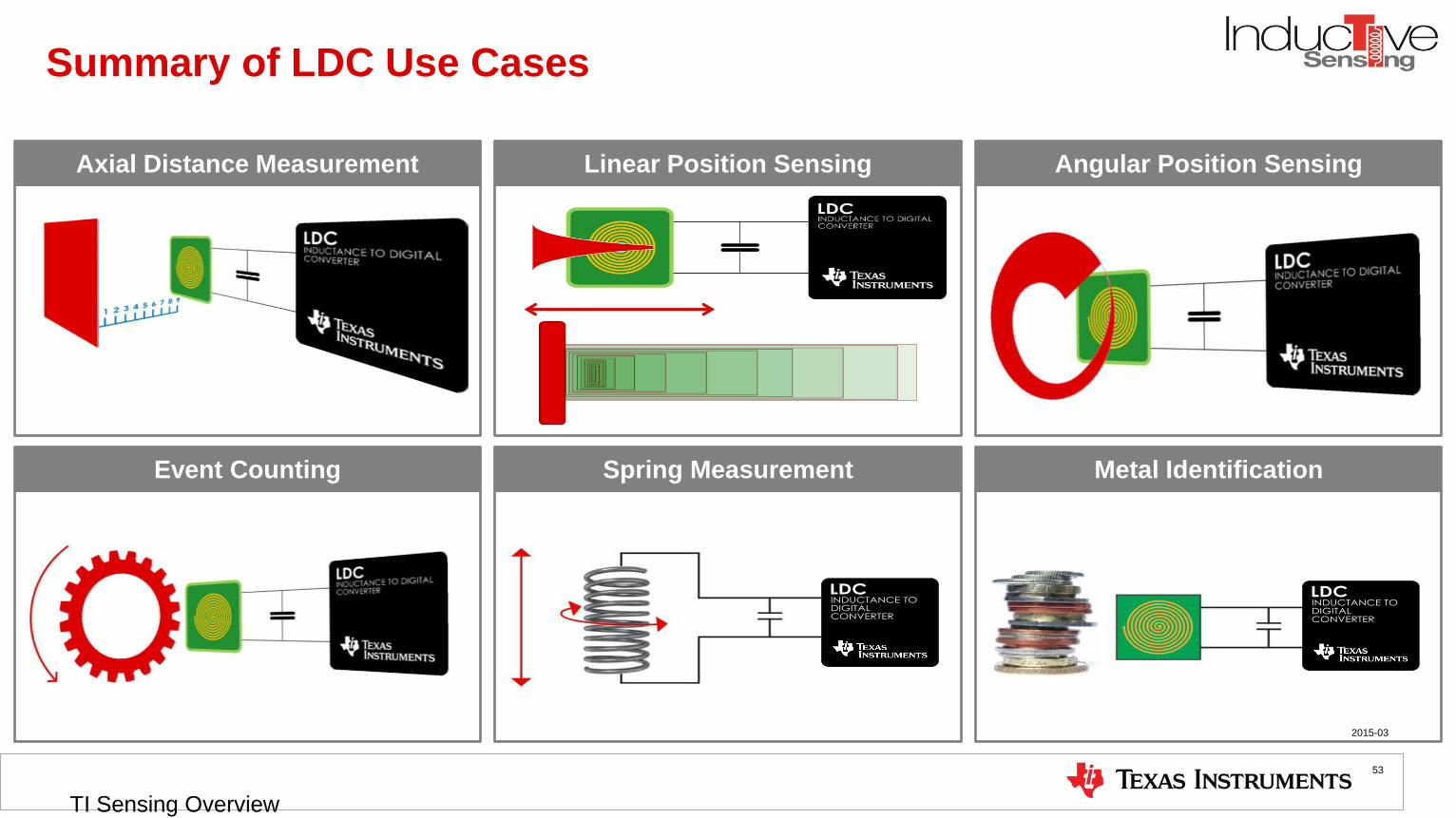
Summary of LDC Use Cases
LDCINDUCTANCE TO DIGITALCONVERTER
LDCINDUCTANCE TO DIGITALCONVERTER
Axial Distance Measurement Linear Position Sensing Angular Position Sensing
Metal Identification Event Counting Spring Measurement
2015-03
TI Sensing Overview
53

Inductive Sensing Solutions
54
TI’s new inductive
sensing solutions
Number of channels
L-
Reso
luti
on
(b
its)
12
24
28
1 2 4
LDC1000(Q)
24-bit L/16-bit Rp
1-ch
8
LDC1041
24-bit L/8-bit Rp
1-ch
LDC1051
8-bit Rp
1-ch
LDC1312
12-bit L
2-ch
LDC1314
12-bit L
4-ch
LDC1612
28-bit L
2-ch
LDC1614
28-bit L
4-ch
Released
New 2015-03
TI Sensing Overview

Key New Features and Benefits: LDC1312, LDC1314, LDC1612, LDC1614
55
Multiple channels • Lower cost and size
• Lower power
Well-matched channels • Allow for easy compensation of environmental changes and aging
Simple design • Allows for faster prototyping
• Reduces development cost and time
Improved
performance
• Enables higher performance & efficiency
• Extended sensing range
Wider sensor frequency range • Allows for smaller PCB coils and reduced size in space-constrained systems
Feature • Benefits
2015-03
TI Sensing Overview

LDC1000-Q1
2015-03 TI Sensing Overview
56
5V, 1-ch, High resolution LDC, SPI, AECQ100 – Grade 0 & 1
Features
• Supply Voltage (Analog) = 5.0V
• Current Consumption
• Active = 1.7mA, typ
• Sleep = 200uA, typ
• Channels = 1
• Oscillation Frequency = 5kHz-5MHz
• Resolution = 16-bit (Rp) / 24-bit (L)
• Interface = 4-Wire SPI
• Temperature Range = -40C to +150C
• Package = TSSOP16
• Automotive qualification: AECQ100 - Grade 0 & 1
Applications
• Climate Control
• Headlight Position Control
• Power Seat Position Sensor
• Side Mirror Position
• Transmission Control
• Steering wheel angle Sensor
• Pedal travel Sensor
Benefits
• Magnet-free operation
• Lower system costs
• Remote sensor location
• Higher reliability
• Greater system design flexibility
• Sub-micron resolution
• Contactless sensing
• Immunity to non-conductive interferences
• Limitless design possibilities

LDC1000/1041/1051
2015-03 TI Sensing Overview
57
5V, 1-ch, High resolution LDC with SPI interface
Features
• Operating supply voltage: 5V, typ
• Current Consumption
• Active = 1.7mA, typ
• Sleep = 250uA, typ
• Channel count: 1
• Oscillation Frequency: 5kHz-5MHz
• Resolution:
• LDC1000: 16-bit (Rp) | 24-bit (L)
• LDC1041: 8-bit (Rp) | 24-bit (L)
• LDC1051: 8-bit (Rp)
• Output: 4-Wire SPI
• Temperature range: -40°C to +125°C
• Package: WSON16
Applications
• High-resolution linear position sensing
• High-resolution angular position sensing
• Metal identification
• Paper stack height measurement
• Gear tooth counting
• Spring motion sensing
Benefits
• Magnet-free operation
• Adjustable sensing range via coil design
• Lower system cost using PCB sense elements
• Remote sensor placement
• High durability/contactless technology
• Insensitivity to environmental interference (dirt, dust, water)
• High Resolution

LDC1612/14
2015-03 TI Sensing Overview
58
3.3V, 2–/4–ch, 28–bit LDCs for Inductive Sensing
Features
• Multiple channels
• 2-ch: LDC1612
• 4-ch: LDC1614
• Well matched channels with 4.08 ksps max sampling rate
• Resolution: 28 bits
• Sensor frequency range: 1kHz to 10 MHz
• Power consumption:
• Active: 540uA/ch (LDC1614)
• Sleep: 35uA
• Shutdown: 200nA
• Package
• LDC1612: 12-pin WSON
• LDC1614: 16-pin WQFN
Applications
• Knobs in consumer, appliance, & automotive
• Incremental linear and rotational encoders
• Buttons in home electronics, wearables, & factories
• Keypads, HMI, and POS in factories & appliances
• Slider buttons in consumer
• Metal detection in industrial & consumer
• Flow meters in consumer and appliances
Benefits
• Up to four channels enables multiple sensors in minimum system size, cost, and
power
• Well-matched channels allow for easy compensation of environmental changes and
aging
• High resolution enables better end-system performance and efficiency and
extended sensing range
• Easy-to-use: sensor just needs to be within 1kHz and 10 MHz, simplifying and
accelerating prototyping
• Large sensor frequency range supports very small PCB coils, supporting space-
constrained applications

LDC1312/4
2015-03 TI Sensing Overview
59
5V, 2–/4–ch, 12–bit LDCs for Inductive Sensing
Features
• Multiple channels:
• 2-ch: LDC1312
• 4-ch: LDC1314
• Well matched channels w/ 13.3 ksps max. sampling rate
• Sensor frequency range: 1kHz to 10 MHz
• Power consumption:
• Active: 540uA/ch (LDC1314)
• Sleep: 35uA
• Shutdown: 200nA
• Package
• LDC1312: 12-pin WSON
• LDC1314: 16-pin WQFN
Applications
• Knobs in consumer, appliance, & automotive
• Incremental linear and rotational encoders
• Buttons in home electronics, wearables, & factories
• Keypads, HMI, and POS in factories & appliances
• Slider buttons in consumer
• Metal detection in industrial & consumer
• Flow meters in consumer and appliances
Benefits
• Up to four channels enables multiple sensors in minimum system size, cost, and
power
• Well-matched channels allow for easy compensation of environmental changes and
aging
• Easy-to-use: sensor just needs to be within 1kHz and 10 MHz, simplifying and
accelerating prototyping
• Large sensor frequency range supports very small PCB coils, supporting space-
constrained applications

Light Sensors
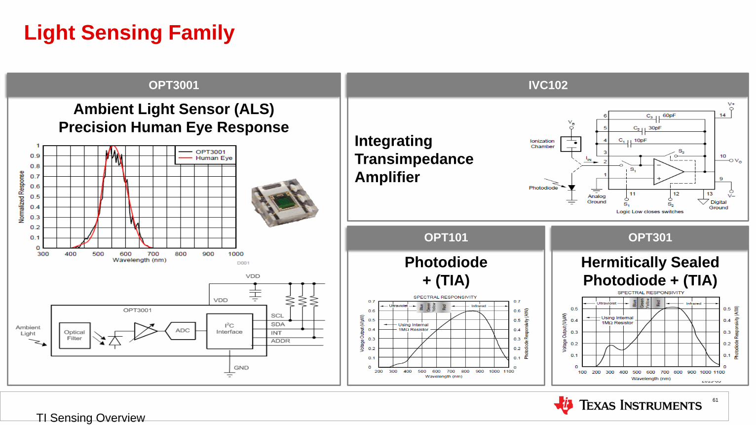
Light Sensing Family
2015-03
TI Sensing Overview
61
IVC102
Integrating
Transimpedance
Amplifier
OPT301
Hermitically Sealed
Photodiode + (TIA)
OPT101
Photodiode
+ (TIA)
OPT3001
Ambient Light Sensor (ALS)
Precision Human Eye Response

Ambient Light Sensing
2015-03
TI Sensing Overview
62
Backlight
Control
Artificial
Illumination
Example Applications
TI’s Ambient Light
OPT3001: Precision Human Eye Matching
Features: >99% Human Eye Rejection
23-Bit Effective Resolution
0.01 Lux to 83K Lux
2.5uA (max) Quiescent Current
2.0 x 2.0mm
Benefits of an Ambient Light Sensor
• Light intensity metering seen by the human
eye
• Insensitive to changes in light source (sun,
incandescent, florescent, LED…)
Infotainment Thermostats
Building Lighting
Digital Signage
-0.2
0.0
0.2
0.4
0.6
0.8
1.0
1.2
300 400 500 600 700 800 900 1000 1100
Human Eye
OPT3001
Human Eye
Street Lighting

Comparison of Different Sensors Simulated Responses
TI Sensing Overview
2015-03
63

Collateral
Forums: Optical Sensors E2E Forum
64 2015-03 TI Sensing Overview

3D ToF Imaging

3D Time of Flight
2015-03
TI Sensing Overview
66
Basic Principle Example Applications
Advantages of ToF
• Direct output of 3D Depth Data
• Reduced Software Complexity vs other 3D Imaging
technologies
• Low Latency
• Depth Range Scalable by Illumination Power
• Strong Low Light Performance
Tools & Support
• TI 3D Party Design Network
• Software Developer’s Kit
Robotics Industrial
Equipment
Inspection &
Scanning
Occupancy
Detection
Bio Kinetics Gesture
Recognition
Video
Conferencing Gaming
Application Processor
or PC
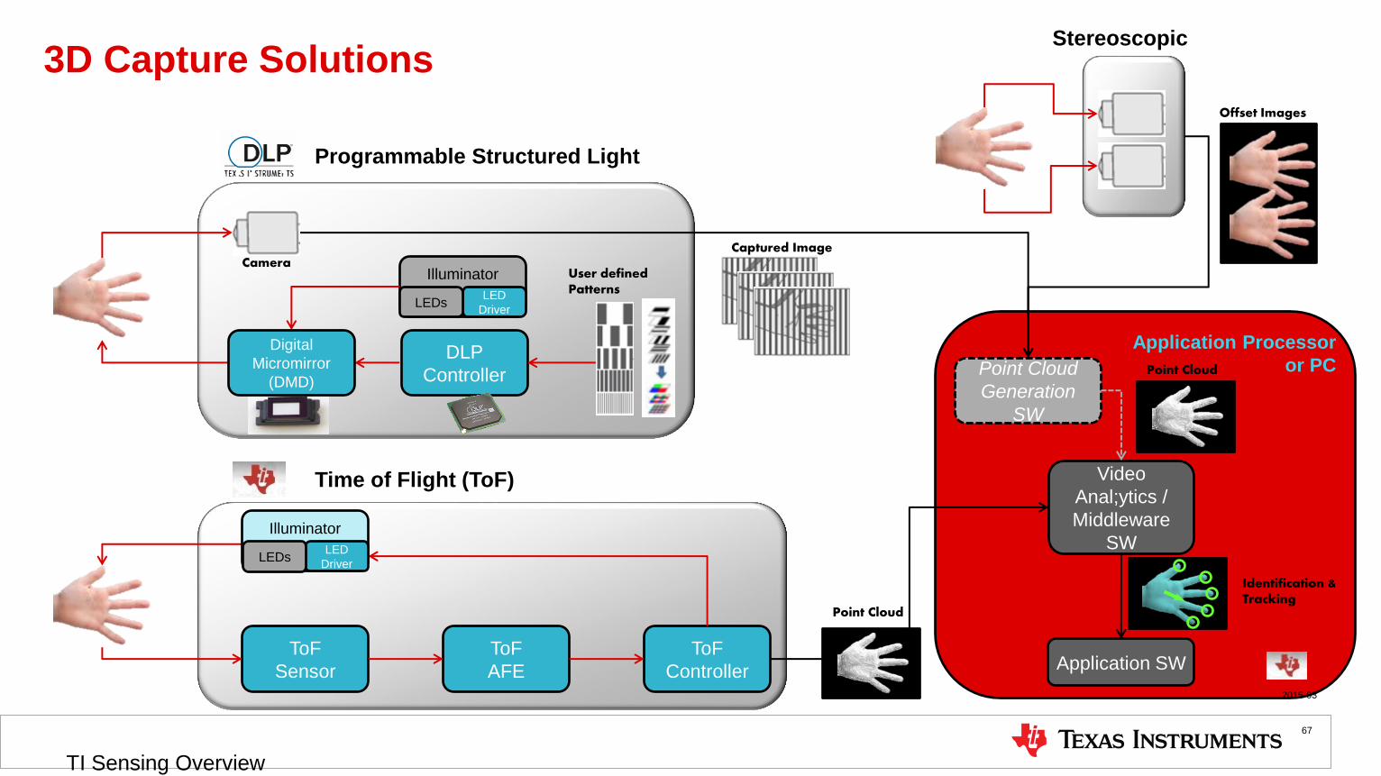
3D Capture Solutions
2015-03
TI Sensing Overview
67
Camera
DLP
Controller
User defined Patterns
Point Cloud
Generation
SW
Illuminator
ToF
Controller
ToF
AFE
ToF
Sensor
Video
Anal;ytics /
Middleware
SW
Application SW
Captured Image
Point Cloud
Point Cloud
LED
Driver LEDs
Illuminator
LED
Driver LEDs
Programmable Structured Light
Identification & Tracking
Time of Flight (ToF)
Stereoscopic
Offset Images
Digital
Micromirror
(DMD)

Comparison of 3D Capture Solutions Time of Flight (ToF) Stereoscopic Vision Fixed Structured Light Programmable Structured Light (DLP)
Operational Principle IR pulse, measure light transit time Two 2D sensors emulate human eyes Single pattern visible or IR illumination, detects
distortion
Multiple pattern visible or IR illumination, detects
distortion
Point Cloud Generation Direct out of chipset High SW Processing Medium SW Processing SW Processing scales with # of patterns
Latency Low Medium Medium Medium
Active Illumination Yes No Yes Yes – Customizable Spectrum
Low Light Performance Good Weak Good Good
Bright Light Performance Medium Good Medium / Weak
Depends on illumination power
Medium / Weak
Depends on illumination power
Power Consumption Medium/High
Scales w/ distance Low Medium
Medium
Scales with distance
Range Short to long range
Depends on illumination power & modulation
Mid range
Depends on spacing between cameras
Very short to mid range
Depends on illumination power
Very short to mid range
Depends on illumination power
Resolution QQVGA, QVGA -> Roadmap to VGA Camera Dependent Camera Dependent WVGA to 1080p -> Roadmap to WQXGA
Depth Accuracy mm to cm
Depends on resolution of sensor
mm to cm
Difficulty with smooth surface mm to cm µm to cm
Scanning Speed Fast
Limited by sensor speed
Medium
Limited by software complexity
Fast
Limited by camera speed
Fast / Medium
Limited by camera speed
Applications
Location X X X
Identification X X X X
Measurement/Inspection X X X X
Biometrics X
UI Control / Gaming X X
Augmented Reality X X X
2015-03
TI Sensing Overview
68

3D Imaging/TOF Sensor Operation
2015-03
TI Sensing Overview
69
ambient
light
22
f
cd
-
-
21
43arctanQQ
Optics/Illumination
3D Imaging Third-Party Design Network
2015-03
TI Sensing Overview
70
Camera Module
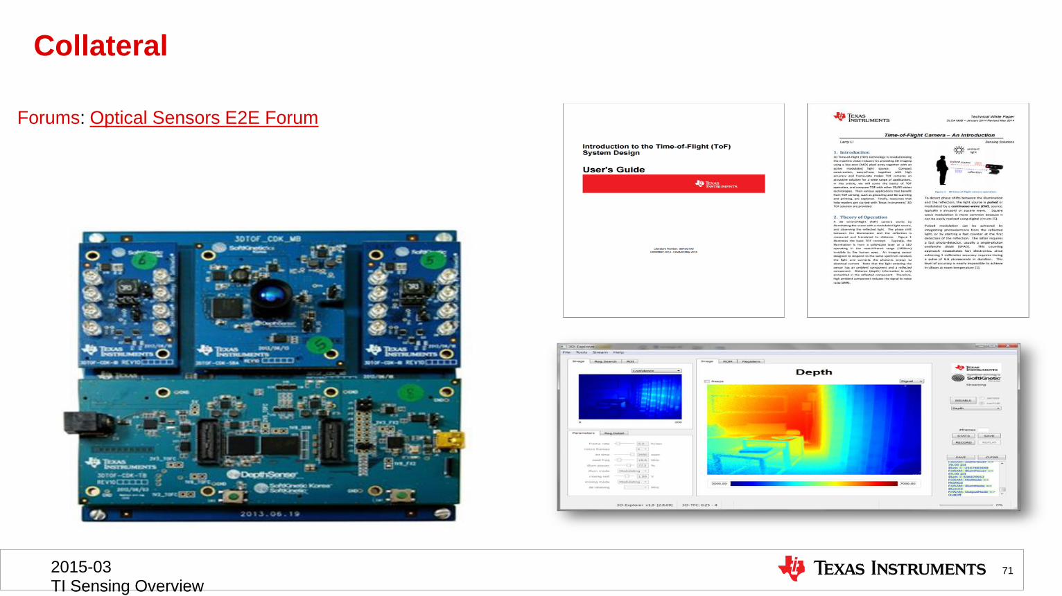
Collateral
Forums: Optical Sensors E2E Forum
71 2015-03 TI Sensing Overview

Mobile Spectroscopy
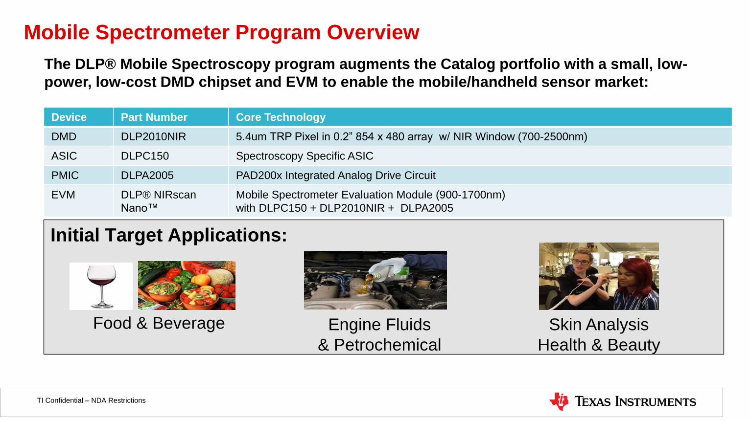
Mobile Spectrometer Program Overview
Initial Target Applications:
Engine Fluids
& Petrochemical
Skin Analysis
Health & Beauty
Food & Beverage
Device Part Number Core Technology
DMD DLP2010NIR 5.4um TRP Pixel in 0.2” 854 x 480 array w/ NIR Window (700-2500nm)
ASIC DLPC150 Spectroscopy Specific ASIC
PMIC DLPA2005 PAD200x Integrated Analog Drive Circuit
EVM DLP® NIRscan
Nano™
Mobile Spectrometer Evaluation Module (900-1700nm)
with DLPC150 + DLP2010NIR + DLPA2005
The DLP® Mobile Spectroscopy program augments the Catalog portfolio with a small, low-
power, low-cost DMD chipset and EVM to enable the mobile/handheld sensor market:
TI Confidential – NDA Restrictions
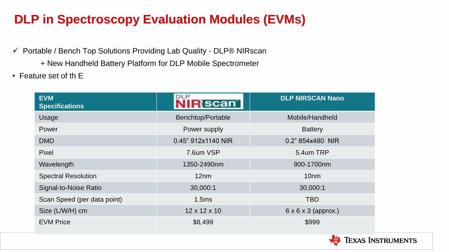
DLP in Spectroscopy Evaluation Modules (EVMs)
Portable / Bench Top Solutions Providing Lab Quality - DLP® NIRscan
+ New Handheld Battery Platform for DLP Mobile Spectrometer
• Feature set of th E
EVM
Specifications
DLP NIRSCAN Nano
Usage Benchtop/Portable Mobile/Handheld
Power Power supply Battery
DMD 0.45” 912x1140 NIR 0.2” 854x480 NIR
Pixel 7.6um VSP 5.4um TRP
Wavelength 1350-2490nm 900-1700nm
Spectral Resolution 12nm 10nm
Signal-to-Noise Ratio 30,000:1 30,000:1
Scan Speed (per data point) 1.5ms TBD
Size (L/W/H) cm 12 x 12 x 10 6 x 6 x 3 (approx.)
EVM Price $8,499 $999
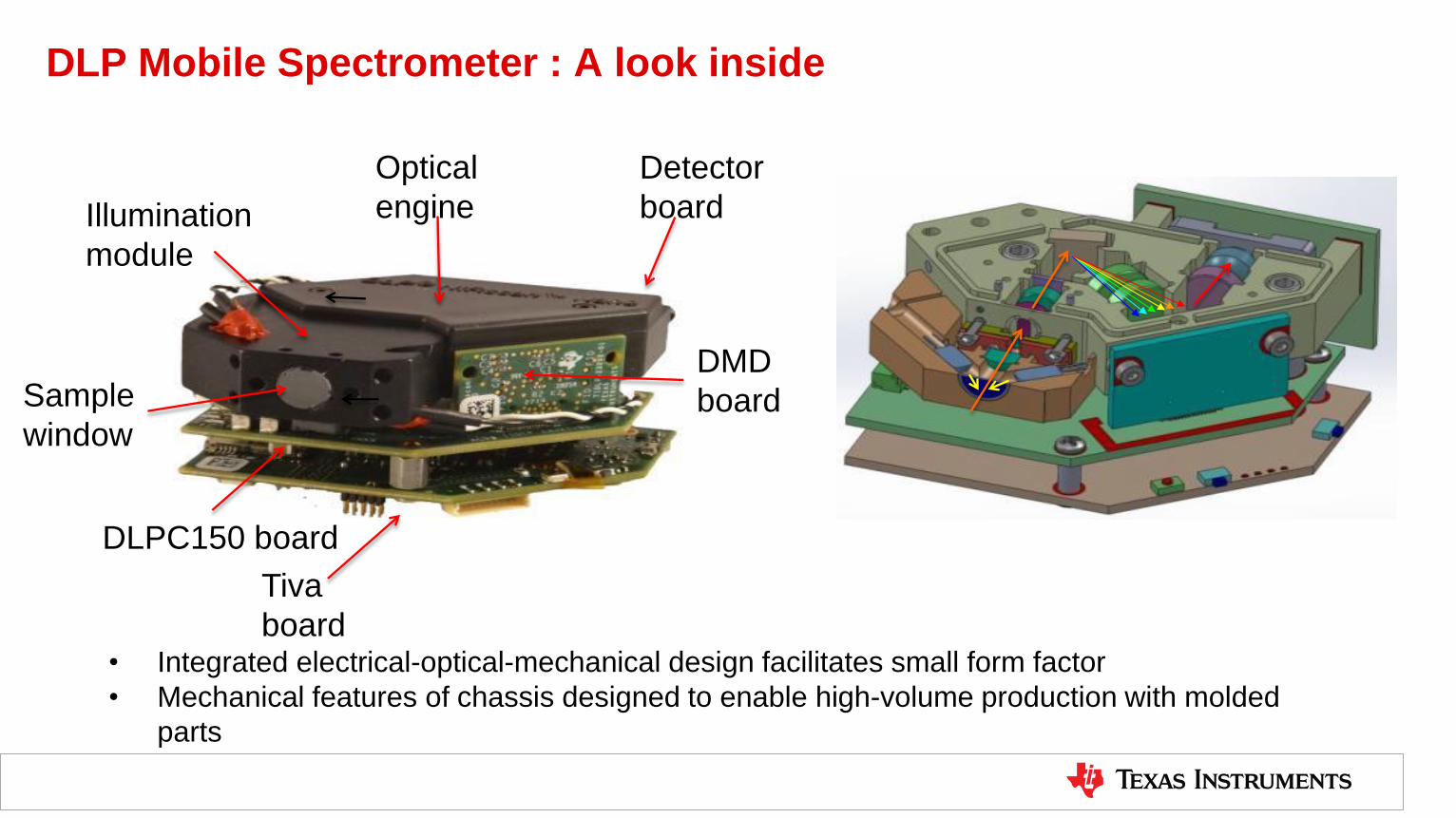
DLP Mobile Spectrometer : A look inside
• Integrated electrical-optical-mechanical design facilitates small form factor
• Mechanical features of chassis designed to enable high-volume production with molded
parts
Illumination
module
Optical
engine
Tiva
board
DMD
board
Detector
board
DLPC150 board
Sample
window
TI Confidential – NDA Restrictions
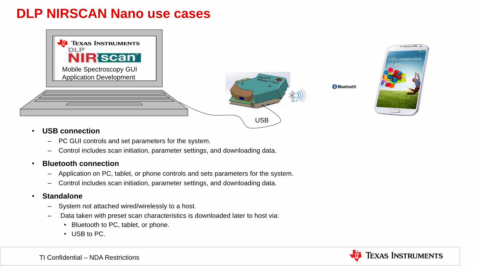
• USB connection
– PC GUI controls and set parameters for the system.
– Control includes scan initiation, parameter settings, and downloading data.
• Bluetooth connection
– Application on PC, tablet, or phone controls and sets parameters for the system.
– Control includes scan initiation, parameter settings, and downloading data.
• Standalone
– System not attached wired/wirelessly to a host.
– Data taken with preset scan characteristics is downloaded later to host via:
• Bluetooth to PC, tablet, or phone.
• USB to PC.
USB
Mobile Spectroscopy GUI
Application Development
DLP NIRSCAN Nano use cases
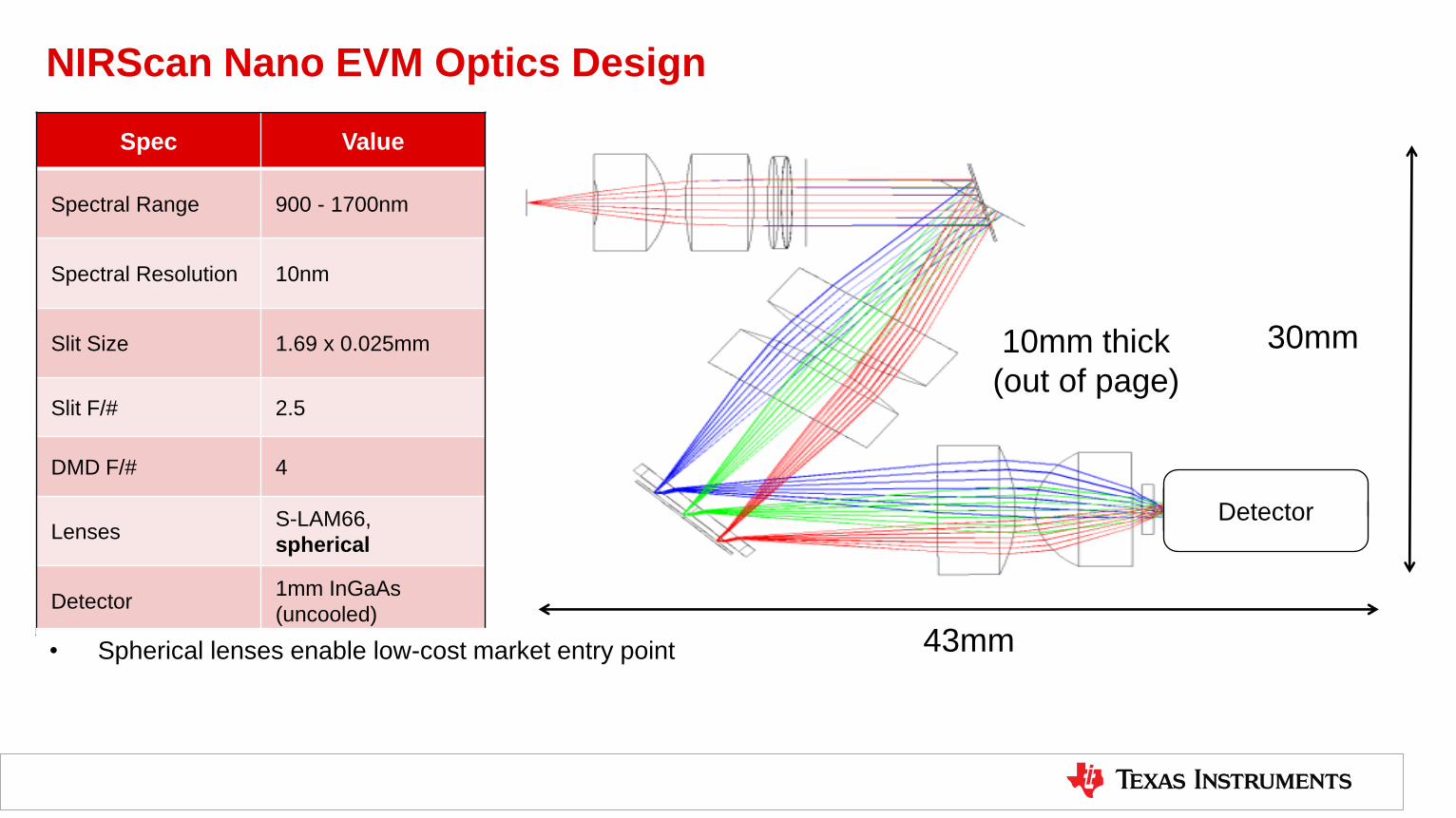
NIRScan Nano EVM Optics Design
Detector
30mm
43mm
Spec Value
Spectral Range 900 - 1700nm
Spectral Resolution 10nm
Slit Size 1.69 x 0.025mm
Slit F/# 2.5
DMD F/# 4
Lenses S-LAM66,
spherical
Detector 1mm InGaAs
(uncooled)
10mm thick
(out of page)
• Spherical lenses enable low-cost market entry point

NIRScan Application Use Cases
79
Food & Agriculture
Food & Agriculture
Pharmaceuticals
Petrochemicals & Plastics
Measurement & Results provided by John Coates, Coates Consulting, LLC

Ultrasonic ToF Sensing (TDC)

Flow Meters
Level/
Concentration
Proximity
Sensing
UltraSound ToF Sensing Technology
Ultrasonic ToF Sensing Solutions
Target Applications
TI’s Solution
TDC1000: 2-channel ToF-to-digital converter
Features: AEC-Q100 qualified for automotive apps
Low power consumption -1.8µA(2SPS)
Programmable excitation: 31.25kHz to 4MHz
Tools & Support
• TI Designs for Flow & Automotive
• Level/Quality measurement: TIDA-00322:
• Flow: TIDM-ULTRASONIC-FLOW-TDC
• Ultrasonic sensing E2E forum
• Application specific evaluation boards
Benefits of Ultrasonic Sensing
• Adaptable to multiple applications and varying tank sizes, pipe
sizes, and fluids
• Low power consumption improves system battery performance
• Detect zero flow or low fluid level 2015-03
TI Sensing Overview
81
Level/ID/Proximity
TDC1000
Flow
Transducer Target Ultrasonic
AFE
Any surface
Time
To
Digital
TDC7200
) ) )
) ) )

Capacitive Sensing (FDC)

Proximity
& Gesture
Liquid/Ice
Sensing
Capacitive Sensing
2015-03
TI Sensing Overview
83
Capacitive Sensing Solutions
Sensor Target Cap-to-
digital
• FDC chip • Copper on PCB
• Copper tape
• Ribbon cable
• ITO
• …
• Conductor
• Human
• Plastic
• Water/Ice
• …
Example Applications
TI’s Solution
FDC1004: 4-channel Cap-to-digital converter
Features: 100pF offset cap
400pF shield driver
Support environmental sensor
Tools & Support
• TI Designs:
• Proximity wakeup (TIDA-00220)
• Liquid level sensing (Q1, 2015)
• Capacitive sensing E2E forum
• Product evaluation board
Benefits of Capacitive Sensing
• Low-cost, flexible sensor design
• Low-power solution
• Contactless, high reliability
• Robust against environmental interferers
• High resolution
• Remote, multi-channel sensing

Capacitive Sensing Overview
2015-03
TI Sensing Overview
84
Benefits of Capacitive Sensing
Low-cost, flexible sensor
Highly reliable by virtue of being contactless
Low power solution
Very sensitive to both conductors and non-conductors
Remote, multi-channel sensing capable
Cap
acit
ive
sen
sin
g
Be
ne
fits
0
Y cm
Sensor is any conductor:
• Copper on PCB
• Conductive ink
• ITO
• Piece of metal
Measure:
• Motion
• Presence
• Level
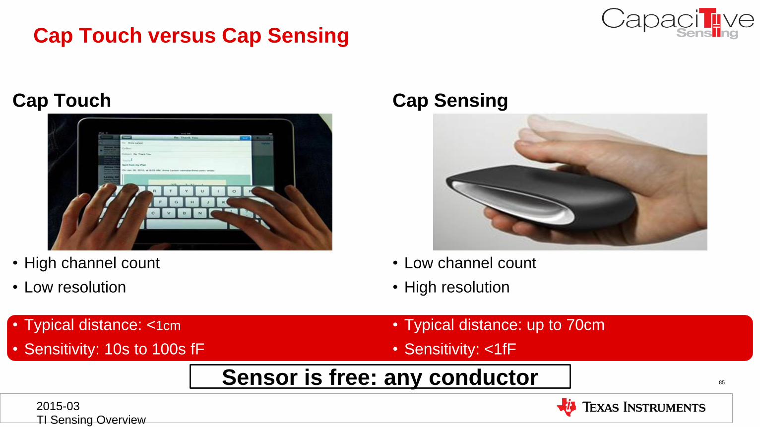
Cap Touch Cap Sensing
85
2015-03 TI Sensing Overview
Cap Touch versus Cap Sensing
• High channel count
• Low resolution
• Typical distance: <1cm
• Sensitivity: 10s to 100s fF
• Low channel count
• High resolution
• Typical distance: up to 70cm
• Sensitivity: <1fF
Sensor is free: any conductor
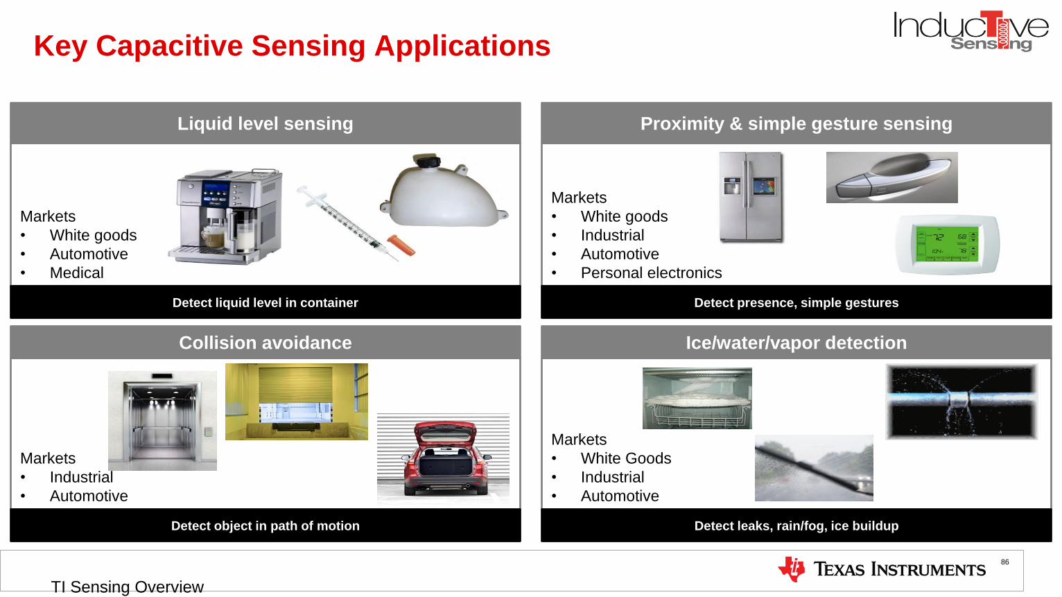
Key Capacitive Sensing Applications
86
Markets
• White goods
• Automotive
• Medical
Markets
• White goods
• Industrial
• Automotive
• Personal electronics
Markets
• Industrial
• Automotive
Markets
• White Goods
• Industrial
• Automotive
Liquid level sensing
Detect presence, simple gestures
Proximity & simple gesture sensing
Detect leaks, rain/fog, ice buildup
Ice/water/vapor detection
Detect object in path of motion
Collision avoidance
Detect liquid level in container
2015-03
TI Sensing Overview

Capacitive Sensing Solutions
2015-03
TI Sensing Overview
87
Accu
rac
y/N
ois
e F
loo
r (a
F)
FDC1004
4-channel
500aF, 750uA
400 sps, QFN
FDC1004Q
4-channel
500aF, 750uA
400 sps, MSOP
Auto Grade 1
FDC1004
4-channel
500aF, 750uA
400 sps, MSOP
Released
Sampling
Q2’15
500
Q3’14 Q1’15 Q3’15
Release Date

FDC1004
2015-03 TI Sensing Overview
88
4–ch General Purpose Cap–to–Digital Converter
Features
• Four cap sensing channels
• 100pF maximum input offset capacitance with large input full-scale range: +/-15pF
• Two 400pF shield drivers
• Low noise floor: 500aF at 100 samples/second
• Programmable sampling rate: 100/200/400 samples/sec
• Low power:
• 750uA active
• 29uA standby at 3.3V
• Packages:
• 10-pin QFN, -40 to +85 degC (released)
• 10-pin VSSOP, -40 to +125 degC (RTM: March/15)
Applications
• Liquid level sensing in refrigerators, coffee machines, automotive, drug pens, and
insulin pumps
• Collision avoidance in automotive, garage doors, elevator doors, automatic doors,
robots
• Proximity and simple gesture sensing in refrigerators, thermostats, audio
equipment, automotive
• Ice/rain/condensation sensing in automotive, coffee makers, refrigerators,
freezers, process control
Benefits
• Four channels enables multiple sensors in minimum system size and cost
• Large offset capacitance enables remote sensing
• Large shield reduces impact of interferers, focuses sensing, and makes system
robust to temp & humidity
• Low noise floor allows for minimum sensor size
• Programmable sampling rate enables optimal speed / performance tradeoff

Key Features and Benefits: FDC1004
89
100pF offset
capacitance
• Enables remote sensing by driving long wires
• Enables longer range and better coverage with larger sensors
Two 400pF
shield drivers
• Enables liquid level sensing that is robust against interferers
• Mitigates interferers and parasitics
• Focus sensor direction
• Mitigate effects of temperature & humidity changes
Supports external
Offset capacitance • Automatically compensate for environmental changes and aging
Feature • Benefits
2015-03
TI Sensing Overview

FDC1004–Q1
2015-03 TI Sensing Overview
90
Automotive Grade 1 4–ch General Purpose Cap–to–Digital Converter
Features
• Four cap sensing channels
• 100pF maximum input offset capacitance with large input full-scale range: +/-15pF
• Two 400pF shield drivers
• Low noise floor: 500aF at 100 samples/second
• Programmable sampling rate: 100/200/400 samples/sec
• Low power:
• 750uA active
• 29uA standby at 3.3V
• Packages:
• 10-pin VSSOP, -40 to +125 degC (RTM: March/15)
Applications
• Liquid level sensing in fuel tanks, washer fluid reservoirs, coolant reservoirs
• Collision avoidance in automotive doors
• Proximity and simple gesture sensing for automotive doors, kick sensors, and
automotive infotainment
• Ice/rain/condensation sensing for rain sensors, windshield fog sensors, and roof
ice/snow sensors
Benefits
• Four channels enables multiple sensors in minimum system size and cost
• Large offset capacitance enables remote sensing
• Large shield reduces impact of interferers, focuses sensing, and makes system
robust to temp & humidity
• Low noise floor allows for minimum sensor size
• Programmable sampling rate enables optimal speed / performance tradeoff
Samples: Now
RTM: Apr–15

Hall Effect Sensing (DRV)

DRV502x/3x:
Digital
Switch
DRV501x:
Digital
Latch
DRV505x: Analog Bipolar Output
Hall Effect Sensors
2015-03
TI Sensing Overview
92
Hall Effect Sensor Solutions
TI Solutions and Advantage
• Simple, low-cost, and easy to design
• Highly reliable sensing with no moving parts
• Immune to grease, dust, dirt, air, RF noise
• Stable characteristics across temperature
• Designed for ultra low-power systems
• Low-voltage CMOS process allows easy system integration and no required external
components.
• Reduced sensor bandwidth is adequate for many systems
• Increases lifespan of battery-powered systems
• On-chip protection enables higher system reliability
Target Applications
BLDC motors
Printer covers
Door lock/switch
Valve actuator/damper
Flow meters
Keyboard buttons
Piston detection
Laptop covers
Filter sensor
Dials
Transmission gear position, actuator and oil pump
Sliding doors & windows
HVAC flaps & compressor
Steering lock/immobilization
Clutch position
Pedal position
Power seat
Turbo charger
Throttle position

What is the Hall-effect?
• A sensing technology that detects the presence of a magnetic field
• Mainly used to sense position, speed, and acceleration
2015-03
TI Sensing Overview
93
V
mV
mT
The current’s positive charge carriers are deflected to one side as a
magnetic field is applied (the Lorentz force), inducing an EMF (Hall
voltage) across the Hall element
Hall
element

2015-03
TI Sensing Overview
94
Hall Sensors for Magnetic (Position) Sensing
Detects presence / change in
magnetic field
Material that produces a magnetic
(B) field
Ob
ject
mo
ve
me
nt
Ob
ject
mo
ve
me
nt
Why are Hall sensor ICs commonly used? Hall sensors ICs replace (examples):
• Solid-state device with signal conditioning & protection logic • Hall elements, reed switches
• Highly repeatable operation (no wear or tear) • Mechanical / reed switches
• Contact not required for operation • Mechanical switches, touch sensors
• Immune to dust, dirt, air, RF noise • Optical / capacitive proximity sensors
• Invariable over a wide temp range • Hall elements
• Pin-to-pin compatible and low cost (only 3 pins!) • Inductive sensors
SENSOR
OBJECT

Hall Sensors Features & Value-Adds
Features:
• Chopper-stabilized output
• Large voltage operating range (2.5V-38V)
• Power-on “ready” pulse
• Fast power-on time (35 µsec)
• Fast switching time (13 µsec)
Robust & Reliable:
• Supports high-volt load dump (up to 40V)
• Reverse supply protection (up to -22V)
• Over-current (short-to-ground) protection
• Superior temperature stability over a wide temp range
95
Many Options Available!
• Industrial Hall effect sensors are rated at -40C to 125C
• Automotive-qualified (AEC-Q100) Hall effect sensors are available for Grade 1 and Grade 0 applications:
– Grade 1: -40C to 125C
– Grade 0: -40C to 150C
• 2 package options are available: – 3-pin SOT-23
– 3-pin SIP
2015-03 TI Sensing Overview


