Page 1
8/19/2019 TechPaper-AnaerobicBioreactor
http://slidepdf.com/reader/full/techpaper-anaerobicbioreactor 1/26
CSTR PROCESS DESCRIPTION
In ‘CSTR’ process, which is a high rate process, anaerobic digestion takes place
in the mesophillic range of temperature, i.e. 36o - 40oC. The pH inside the reactor
is usually kept around 7.2 while proper ratio of volatile acid and alkalinity is
maintained.
The following three stages are involved in the process of anaerobic digestion.
a. Hydrolysis: In the process of hydrolysis the complex molecular compounds
i.e. polymers are converted into the simple molecular form i.e. monomers.
b. Acidogenesis: The monomers so formed at the end of hydrolysis process
are converted into volatile fatty acids. Acetic acid forms the major portion of
volatile fatty acids. The process of conversion of monomers into acids is
carried out by a group of anaerobic bacteria known acid formers.
c. Methanogenesis: Acids produced at the end of Acidogenesis process are
converted into carbon dioxide and methane gases. The process of
conversion of acid into gases is carried out by group of anaerobic bacteria
known as methane formers.
In CSTR process all the three stages are carried out in a single reactor. The
bacteria responsible for digestion process are present in reactor and are
maintained in suspension with the help of agitators. The adequate population of
microorganisms is maintained in reactor by recirculating the settled solids from
treated spent wash.
2.0 DESCRIPTION OF THE CSTR SYSTEM
2.1 Wastewater Transport
The effluent from the collection sump shall be fed to the reactor with the help of
feed pumps.
Page 2
8/19/2019 TechPaper-AnaerobicBioreactor
http://slidepdf.com/reader/full/techpaper-anaerobicbioreactor 2/26
2.2 CSTR Reactor
The CSTR Reactor will be erected and fabricated at site using mild steel plates of
designed thickness conforming to I.S. 2062. The roof of the reactor will be fixed
type supported on Grid of ISMB.
The Reactor will be painted from inside using chlorinated rubber paint, whereas
the outside surface will be painted by synthetic enamel or aluminum paint as per
client preference.
The CSTR Reactor has four/ six agitators. One located at center and others
located equidistant along the circumference of reactor. The agitators are
designed in such a way that the entire contents of reactor are in completelymixed condition. This constant agitation helps to maintain active bacteria in
suspension. These bacteria utilize organic matter present in wastewater and
produce biogas.
The solids are separated from the outlet of reactor in Lamella Clarifier and
returned to the system by recirculation pumps. This recirculation of settled solids
helps to maintain adequate population of active bacteria inside reactor.
2.3 Treated effluent discharge
In CSTR reactor the raw spent wash is introduced from top of reactor. The
recycled sludge is also introduced from the top of the reactor. This mixed liquor
travels downward through the central shaft. In this central shaft agitator provides
adequate mixing of RSW and recycled sludge. From central shaft well mixed
liquor enters reactor near bottom of tank. Inside reactor, the content is kept in
suspension by means of agitators. The treated effluent leaves the system from
top of reactor. This ensures utilisation of head in carrying effluent to further
treatment units.
Page 3
8/19/2019 TechPaper-AnaerobicBioreactor
http://slidepdf.com/reader/full/techpaper-anaerobicbioreactor 3/26
2.4 Biogas Recovery
The biogas produced by anaerobic digestion inside the reactor is collected from
the top of reactor and is conveyed to gasholder. This gasholder is located near
reactor and is equipped with floating roof. This floating roof is very effective tool
in routine operation. The Gas Dome is placed at Reactor roof and is fitted with all
essential safety equipment such as breather valve, flame arrestor etc., The
biogas is then conveyed to blower for further utilization in boiler or biogas
engines.
3.0 CSTR REACTOR – SALIENT FEATURES
The reactor consists of a cylindrical Mild Steel Tank having central mixer and
lateral agitators to ensure complete mixing of the contents inside the reactor.
The reactor is rested on a suitable foundation. The reactor tank base plate is 6-
mm thick plate with 16-mm thick annular plate. The shell thickness varies from 6
mm to 22 mm, height wise. The roof plate shall be of 8-mm thickness. The
corrosion allowance considered is 1.5 mm. Reactor tank inside is painted with
zinc phosphate primer and chlorinated rubber paint.
Steel plates used confirm IS 226. Fabrication of reactor tank is as per IS 803.
4.0 CHIEF DESIGN AND PERFORMANCE PROJECTIONS
DESIGN DATA
Each CSTR reactor is designed to treat yeast free raw spent wash havingfollowing characteristics.
1. Flow - 450 m3/day
2. pH - 4.0 – 4.5 S.U.
3. COD - 120000 mg/L
4. BOD - 45000 mg/L
Page 4
8/19/2019 TechPaper-AnaerobicBioreactor
http://slidepdf.com/reader/full/techpaper-anaerobicbioreactor 4/26
PERFORMANCE PROJECTIONS
Upon reaching the steady state each CSTR reactor would produce the
following results, when operated under optimum design conditions:
1. COD Removal : 65 ± 5 %
2. pH : 7.0 - 7.5
3. Biogas Production : 0.53 ± 5 % m3 /Kg COD Removed
Average Gas Composi tion
1. Methane content : 55 % - 60 %
2. Hydrogen Sulfide : 1.5 % - 2.5 %
3. Carbon Dioxide : 33 % - 43 %.
5.0 UTILITY REQUIREMENTS (CLEINT’S SCOPE)
Sr. No Items
POWER (FOR EACH REACTOR)
Operating HP 77.5
1
Connected HP 117.5
MANPOWER2
1 Chemist in general Shift. One operator in each shift.
AREA REQUIREMENT3
2500 m2.
CHEMICALS & CONSUMABLES
During Start up. Soda ash
Seed sludge
4
During operation. Micronutrients like
Ferric chloride
NiCl2
COCl2
ZnCl2
Page 5
8/19/2019 TechPaper-AnaerobicBioreactor
http://slidepdf.com/reader/full/techpaper-anaerobicbioreactor 5/26
SMART PROCESS DESCRIPTION
Influent HomogenisationRaw effluent i.e. raw spent wash from the distillery shall be carried to treatment
site through suitably designed channel or a closed pipe depending upon the
topography of the site. Raw spent wash shall then be passed through heat
exchanger to bring down the temperature to 38– 40OC. Yeast free raw spent
wash is then mixed with part of reactor content [recirculated back] for pH
adjustment in the Reactor feed tank or Homogenisation Tank. This homogenized
Raw spent wash is then pumped to reactor.
SMART Reactor
The SMART [Structured Media Anaerobic Reactor Treatment] Reactor shall be
tailor made as per your requirement and shall be designed as per guidelines of
IS 803 [Bureau of Indian Standard] or as per your design standard. The reactor
tank shall be rested on floating type civil foundation [this will be confirmed on
receipt of Site Soil Investigation report]. The reactor tank will be erected and
fabricated at site using mild steel plates of designed thickness. The roof of the
reactor will be fixed type supported on Grid of medium grade “I” sections.
The Reactor shall be painted from inside using chlorinated rubber paint, whereas
the outside surface will be painted by synthetic enamel or aluminum paint as per
your preference. The surface preparation as per painting requirement shall be
carried out prior to painting.
The SMART Reactor is partially packed with structured media made out of PVC.
The entire media remains submerged in the reactor content. The bacteria grow
and reside on large surface area provided by media. The bacteria developed on
media surface takes upon organic content of wastewater to metabolize it and
Page 6
8/19/2019 TechPaper-AnaerobicBioreactor
http://slidepdf.com/reader/full/techpaper-anaerobicbioreactor 6/26
produce biogas and resultant biomass. The suitable media supporting
arrangement is provided at the bottom of reactor for media stacking.
The reactor content is kept under constant re-circulation using recirculation
pumps. Each recirculation pump is connected to the suction network, placed next
to the bottom of the reactor. This suction network is designed in such a way that
it sucks reactor content from entire bottom cross sectional area. Thus the
possibility of formation of dead zone is eliminated and the entire reactor is kept
active. All recirculation pumps pour their discharge into Roof Feed Tank.
The distribution Network provided at the top of SMART Reactor will then
distribute feed tank contents over inside top area of reactor. The distribution
pipes kept submerged in reactor content.
Overflow from SMART Reactor
As SMART reactor is down flow, the treated effluent is collected from the bottom
of reactor. To utilize head available, the overflow arrangement is so designed
that the treated effluent is discharged at reactor liquid level. The suitable number
of overflow weirs are provided as per process requirement.
Biogas Recovery
The biogas produced by SMART reactor shall be recovered at the Gas Dome
provided at the roof of the tank. All necessary safety arrangements such as
pressure & vacuum relief tanks are provide are provided on the roof tank. The
biogas collected at Gas Dome is then taken to blower for further utilization in
boiler or biogas engines.
Page 7
8/19/2019 TechPaper-AnaerobicBioreactor
http://slidepdf.com/reader/full/techpaper-anaerobicbioreactor 7/26
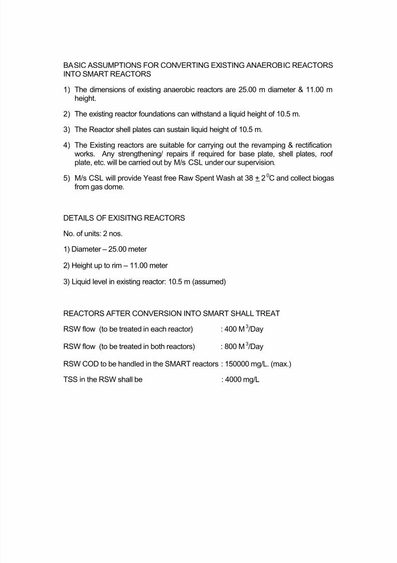
BASIC ASSUMPTIONS FOR CONVERTING EXISTING ANAEROBIC REACTORSINTO SMART REACTORS
1) The dimensions of existing anaerobic reactors are 25.00 m diameter & 11.00 m
height.
2) The existing reactor foundations can withstand a liquid height of 10.5 m.
3) The Reactor shell plates can sustain liquid height of 10.5 m.
4) The Existing reactors are suitable for carrying out the revamping & rectificationworks. Any strengthening/ repairs if required for base plate, shell plates, roofplate, etc. will be carried out by M/s CSL under our supervision.
5) M/s CSL will provide Yeast free Raw Spent Wash at 38 + 20C and collect biogasfrom gas dome.
DETAILS OF EXISITNG REACTORS
No. of units: 2 nos.
1) Diameter – 25.00 meter
2) Height up to rim – 11.00 meter
3) Liquid level in existing reactor: 10.5 m (assumed)
REACTORS AFTER CONVERSION INTO SMART SHALL TREAT
RSW flow (to be treated in each reactor) : 400 M3/Day
RSW flow (to be treated in both reactors) : 800 M3/Day
RSW COD to be handled in the SMART reactors : 150000 mg/L. (max.)
TSS in the RSW shall be : 4000 mg/L
Page 8
8/19/2019 TechPaper-AnaerobicBioreactor
http://slidepdf.com/reader/full/techpaper-anaerobicbioreactor 8/26
PERFORMANCE PROJECTIONS
FLOW (in each reactor) - 400 M3/ Day
BOD - 80+ 5 % Reduction
COD - 60 + 5 % Reduction
BIOGAS - 0.53 + 5 % m3/Kg COD Destroyed
BATTERY LIMITS FOR COST ESTIMATION
Effluent (Yeast free) at 38oC - At inlet of existing feed tank
Power - At the respective drives
Biogas - At Gas Dome out let
Treated Effluent/Sludge/Foam - One meter away from SMART tank
SALIENT FEATURES OF SMART REACTOR
It is Fixed Film, Fixed Bed reactor.
It is mesophillic reactor i.e. it operates best in temp range of 38 – 40 0C.
It is provided with specially designed Structured Rigid PVC Plastic Media
to maintain high microbial population.
It provides maximum substrate to microorganism contact by appropriate
recirculation ratio.
The reactor is provided with following features to ensure efficient
performance and safety of the reactor:
Built in gas collection system, hence no additional gasholder is required.
Suitable number of overflow-weirs designed to serve as pressure breakers
in case of emergency.
Pressure cum Vacuum breaker tanks, in case pressure goes out of
operating range in case of emergency.
Flare stack to flare the biogas generated in case it is not used.
Instrumentation for online measurement of Feed and Gas flow
If required the higher instrumentation can also be incorporated as per your
requirement.
Page 9
8/19/2019 TechPaper-AnaerobicBioreactor
http://slidepdf.com/reader/full/techpaper-anaerobicbioreactor 9/26
SALIENT FEATURES OF STRUCTURED MEDIA
Specially designed made out of polyvinyl chloride- the most
chemically resistant thermoplastic material.
Provides large surface area (95-105 m2/m3 of media) and 95%
voids for immobilization of bacteria and their subsequent
growth.
Media fills are self-supporting and can be stacked up to 20 feet
without intermediate support.
Plastic material is manufactured under strict quality control and
tested thoroughly for uniformity of color, smooth edges,thermoforming properties, and contamination.
Media sheets are rigorously tested before use and strict control
is exercised on its quality.
ADVANTAGES OF SMART SYSTEM
a. Dilution Water :
SMART Reactor can handle raw spent wash having COD up to 1,50,000
mg/L without any dilution.
b. Higher Organic Loading Rate:
SMART reactor has the highest loading rate in terms of COD per m3 of
reactor volume and thus requires smaller tank.
c. Special Media:
SMART reactor employs honeycomb type, specially designed geometrically
structured rigid PVC media to immobilize the bacteria inside the reactor.
This immobilization of the bacteria on the specially designed performed
media measures that
Page 10
8/19/2019 TechPaper-AnaerobicBioreactor
http://slidepdf.com/reader/full/techpaper-anaerobicbioreactor 10/26
I) The bacteria are neither washed away nor settled at the bottom of the
reactor tank.
ii) All through the 24 hours of the day and 365 days of the year, there is an
optimum (designed) contact between the bacteria and the organic
impurities contained in raw spent wash, ensuring continuous generation of
biogas at the optimum designed level.
d. Reliability
Due to structured media biomass attachment, promised performance in
term of BOD/COD reduction and Biogas generation is available every day
of the year.
e. Sludge recycling
SMART reactor does not need any recycling of anaerobic sludge, which is
even otherwise, difficult to settle.
f. Faster Restart
Even after long factory shutdown of ONE week, system restarts in 72 hours.
(No loss of biogas. No worry of what to do with wastewater while the
system struggles to come back to stream).
g. Most Rugged system
Can withstand variation in flow, pH, COD concentration etc. without system
going sour.
h. Lower operating Cost
The system has low power consumption i.e. power is required for only feed
and reticulation pumps.
i. Higher digestion
SMART reactor reduces the initial COD by 60 – 70 %, consistently and
produces biogas up to 0.50 - 0.56 m3/kg of COD digested.
Page 11
8/19/2019 TechPaper-AnaerobicBioreactor
http://slidepdf.com/reader/full/techpaper-anaerobicbioreactor 11/26
j. Easy Maintenance
As there are no moving parts inside the digester, no pulsating flows, no
backwash, no sludge recycle, simple pump operators even High school
level education can run the system.
k. pH Neutralization
SMART reactor does not need any alkali/acid for pH neutralization for day
to day operation.
l. Chemicals and Nutrients
No chemicals and nutrients are required for day-to-day operation.
m. Toxicity
As only TOP of bacterial film is exposed in SMART reactor against the
entire bacterial population in other anaerobic systems like UASB, SMART
reactor can withstand higher toxic shock load.
n. Smell nuisance
There is no smell nuisance in the vicinity of SMART reactor.
o. Appearance
A system is aesthetically pleasing and extremely neat and clean (people
visiting our installation feel that it does not look like an ETP).
p. Life cycle cost
Life cycle cost of SMART system is the lowest in spite of its higher capital
cost because of:
a. Lowest operation and maintenance cost and
b. Higher and consistent biogas generation compared to other Non Media
anaerobic systems available in India.
Page 12
8/19/2019 TechPaper-AnaerobicBioreactor
http://slidepdf.com/reader/full/techpaper-anaerobicbioreactor 12/26
TECHNIC L PROPOS L
1.0 BIPHASIC SEQUENCING UASB PROCESS BASICS
The Up Flow Anaerobic Sludge Blanket (UASB) process is a high rate
anaerobic treatment process where the bacteria responsible for anaerobic
digestion are present in the form of sludge blanket. The bacteria grow and reside
as bacterial flocs suspended in the up-flow effluent stream. The bacteria take
upon organic content of wastewater to metabolize it and produce biogas and
biomass.
The distribution network provided from the top of the UASB Reactor, which
distributes the feed effluent uniformly inside reactor.
In “ SEQUENCING UASB” process, the effluent feed into the reactor is based on
the concept of intermittent induction of effluent at different sludge blanket zones
in time sequence by a PLC controlled feeding system. The process of conversion
of organic matter into biogas occurs through a group of anaerobic bacteria
residing in the sludge blanket.
In this present treatment scheme, ‘BIPHASIC’ treatment process is adopted
where acetogenesis and methanogenesis is bio-engineered into two separate
tanks – the Acidogenic Reaction Tank (ART) and the Methanogenic Reaction
Tank (MRT). Here the MRT is operated in SEQUENCING UASB mode.
The pH inside the ART is usually in acidic range and the pH of the MRT is kept
around 7.2 while proper ratio of volatile acid and alkalinity is maintained.
The bacteria responsible for digestion process are present in ART and S-UASBR
and are maintained in suspension. The adequate population of microorganisms
is maintained in reactors by recirculating the active biomass.
Page 13
8/19/2019 TechPaper-AnaerobicBioreactor
http://slidepdf.com/reader/full/techpaper-anaerobicbioreactor 13/26
2.0 BIPHASIC S-UASB PROCESS DESCRIPTION
2.1 Process description
The effluent shall be passed through serpentine sedimentation chamber to
remove settlable yeasts from the raw spent wash (RSW) and the yeast free RSW
is collected in a collection sump. The RSW from the collection sump shall be
pumped into the Acidogenic Reaction Tank (ART).
In the ART, the complex organics in the wastewater is subjected to hydrolysis
and acidification. In the process of hydrolysis the complex molecular compounds
i.e. polymers are converted into the simple molecular form i.e. monomers. The
monomers so formed at the end of hydrolysis process are converted into volatilefatty acids. Acetic acid forms the major portion of volatile fatty acids. The process
of conversion of monomers into acids is carried out by a group of anaerobic
bacteria known acid formers.
The process parameters specific to hydrolysis and acidification are precisely
controlled in the ART to achieve the maximum efficiency. The pH correction of
the highly acidic spent wash is achieved in this reactor. During the start-up of the
plant, pH shall be controlled by adding alkaline buffer. Later, pH correction and
control is achieved using alkalinity generated in the methanogenesis stage, by
recycling a part of the MRT overflow in the ART. The ART helps in handling the
shock loading to the MRT and faster recovery from any process upset.
The acidified effluent from ART shall be transferred to the Methanogenic
Reaction Tank (MRT), ie the S-UASB Reactor. In the S-UASB Reactor , acids
produced at the end of acidogenesis process are converted into carbon dioxide
and methane gases. The process of conversion of volatile organic acids into
biogas is carried out by group of anaerobic bacteria known as methane formers.
Page 14
8/19/2019 TechPaper-AnaerobicBioreactor
http://slidepdf.com/reader/full/techpaper-anaerobicbioreactor 14/26
2.2 The S-UASB Reactor
The S-UASB Reactor and the ART shall be tailor made as per your requirement
and shall be designed as per guidelines of IS 803 [Bureau of Indian Standard].
The reactor tanks will be erected and fabricated at site using mild steel plates of
designed thickness. The roof of the S-UASB Reactor will be fixed type supported
on Grid of medium grade “I” sections.
The reactor tanks shall be painted from inside using epoxy paint, whereas the
outside surface will be painted by synthetic enamel or aluminum paint as per
your preference. The surface preparation as per painting requirement shall be
carried out prior to painting.
The S-UASB Reactor is a covered tank with feed distribution pipelines entering
the reactor from top. The feed lines are provided PLC controlled actuated
valves with auto ON/ OFF level switches. At every preset time interval, each auto
valve shall open to allow the feed effluent to enter into the specific zone of the
reactor. The bacteria responsible for digestion process are present in the form of
sludge blanket. The bacteria grow and reside as bacterial flocs suspended in the
up-flow effluent stream. These bacteria utilize the volatile organic acids present
in wastewater to produce biogas.
The solids are separated at the inbuilt clarification system at the top of the S-
UASB Reactor and returned to the system by gravity. Thus the sludge blanket of
active bacteria inside reactor is maintained.
2.3 Treated effluent discharge
In SEQUENCING UASB system, the raw spent wash is introduced into the
MRT. The treated effluent leaves the system after clarification in tube settling
zone. This ensures utilization of head in carrying effluent to further treatment
units.
Page 15
8/19/2019 TechPaper-AnaerobicBioreactor
http://slidepdf.com/reader/full/techpaper-anaerobicbioreactor 15/26
2.4 Biogas Recovery
The biogas produced by anaerobic digestion inside the ART is released to the
atmosphere since it contains mainly carbon-di-oxide. The biogas generated
inside the MRT is rich in methane and is collected from the top of reactor. It is
conveyed to gasholder. The gasholder is located near the MRT and is equipped
with floating roof. This floating roof is very effective tool in routine operation. The
Gas Dome is fitted with all essential safety equipment such as pressure valve,
flame arrestor etc., The biogas is conveyed to blower for further utilization in
boiler or biogas engines.
6.0 CHIEF DESIGN AND PERFORMANCE PROJECTIONS
DESIGN DATA
The SEQUENCING UASB system is designed to treat yeast free raw
wastewater having following characteristics:
5. Flow - 250 m3/day
6. pH - 4.5 S.U.
7. COD - 75000 mg/L
8. BOD - 35000 mg/l
9. Total Solids - 4000 - 5000 mg/l
PERFORMANCE PROJECTIONS
Upon reaching the steady state the system would produce the following
results, when operated under optimum design conditions:
4. BOD Removal : 85 ± 5 %
5. COD Removal : 65 ± 5 %
6. Biogas Production : 0.53 ± 5 % m3 /Kg COD Removed
Average Gas Composition
1. Methane content : 55 % - 65 %
2. Hydrogen Sulfide : 2.5 % - 3.5 %
3. Carbon Dioxide : 32 % - 42 %.
Page 16
8/19/2019 TechPaper-AnaerobicBioreactor
http://slidepdf.com/reader/full/techpaper-anaerobicbioreactor 16/26
MASS BALANCE FOR SEQUENCING UASB REACTOR
Outlet (approx)
7.0 UTILITY REQUIREMENTS (CLEINT’S SCOPE)
Sr. No Items Specifications
Operating HP 17.5 (approx.) 1 Power
Connected HP 34 (approx.)
2 Manpower 1 Chemist in general Shift. One operator in each
shift.
3 Area 700 m2 (approx.)
During Start up. Soda ash, seed sludge4 Chemicals &
consumables During operation. Micronutrients.
Bio-gas Production (approx)CODRemoved 65%
of total COD
Rate of gasproduction 0.53
m3/kg of CODremoved
Sludge Production (approx.)
Qty
121
(±10%) kg/day
Flow 250 m3/day
COD 26250 mg/l
BOD 7000 mg/l
COD Load 6562 Kgs/d
Inlet (approx.)
Flow 250 m3/day
COD 75000 mg/l
BOD 35000 mg/l
COD Load 18750 kgs/day
S-UASB
DIGESTER
Page 17
8/19/2019 TechPaper-AnaerobicBioreactor
http://slidepdf.com/reader/full/techpaper-anaerobicbioreactor 17/26
V1
V3
V2V4
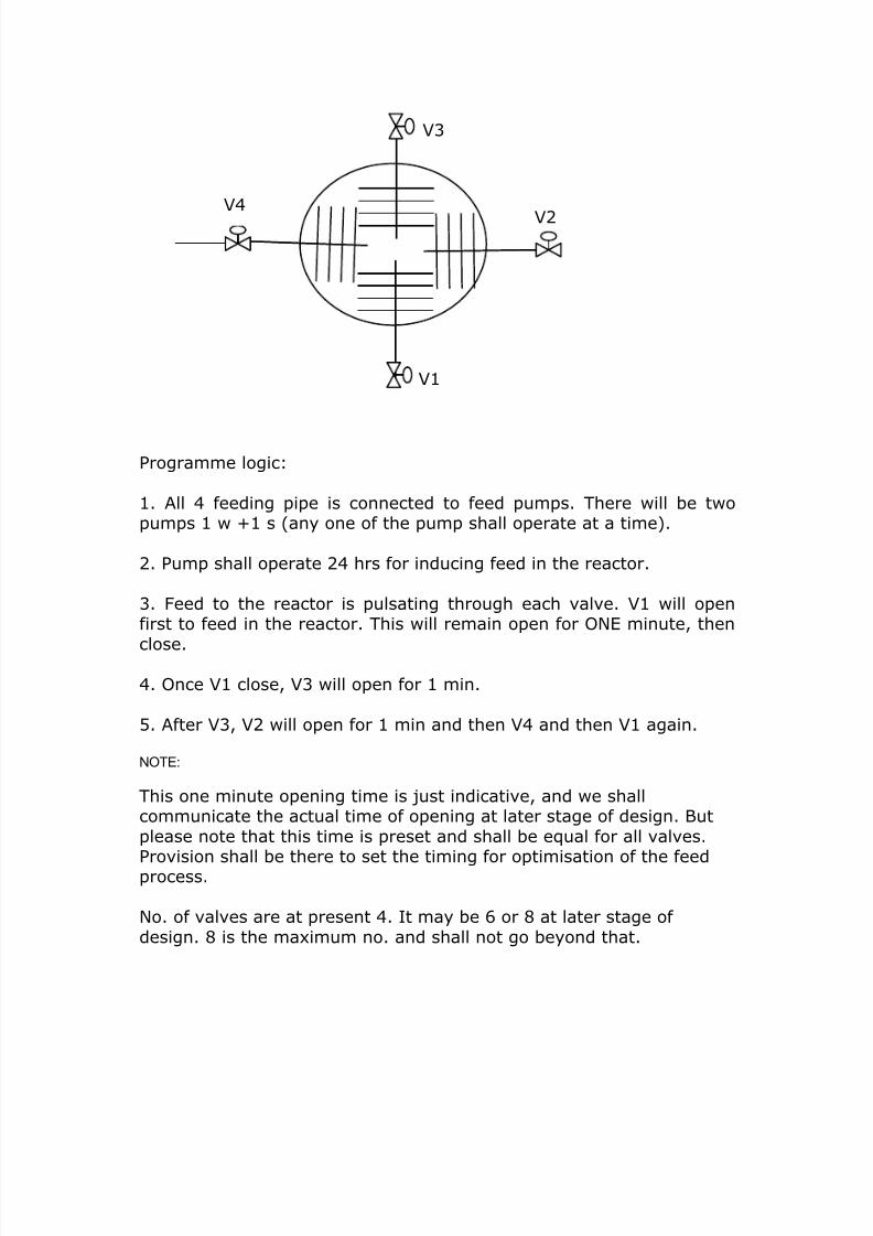
Programme logic:
1. All 4 feeding pipe is connected to feed pumps. There will be twopumps 1 w +1 s (any one of the pump shall operate at a time).
2. Pump shall operate 24 hrs for inducing feed in the reactor.
3. Feed to the reactor is pulsating through each valve. V1 will openfirst to feed in the reactor. This will remain open for ONE minute, then
close.
4. Once V1 close, V3 will open for 1 min.
5. After V3, V2 will open for 1 min and then V4 and then V1 again.
NOTE:
This one minute opening time is just indicative, and we shallcommunicate the actual time of opening at later stage of design. But
please note that this time is preset and shall be equal for all valves.Provision shall be there to set the timing for optimisation of the feedprocess.
No. of valves are at present 4. It may be 6 or 8 at later stage of
design. 8 is the maximum no. and shall not go beyond that.
Page 18
8/19/2019 TechPaper-AnaerobicBioreactor
http://slidepdf.com/reader/full/techpaper-anaerobicbioreactor 18/26
TECHNICAL PROPOSAL
1.0 PROCESS BASICS
The Thermophillic Anaerobic Reactor process being offered by ‘LARS
ENVIRO’ is based on the concept of anaerobic conversion of organic matter into
biogas. The process of conversion of organic matter into biogas occurs through a
group of anaerobic bacteria.
In ‘’ Thermophillic Anaerobic Reactor process, which is a high rate process,
anaerobic digestion takes place in the thermophillic range of temperature, i.e. 50o
- 57oC, conditions suitable for thermophillic bacteria. The pH inside the reactor is
usually kept around 7.2 while proper ratio of volatile acid and alkalinity is
maintained. Because biochemical reaction rates increase with temperature,
doubling with every 10oC rise in temperature until a limiting temperature is
reached, thermophillic process is much faster than mesophillic process (where
reaction takes place at temperatures between 35oC – 45oC).
The bacteria responsible for thermophillic digestion process are present in
reactor and are maintained in suspension with the help of biogas re-circulation
within the reactor. The adequate population of microorganisms is maintained in
reactor by recirculating the settled solids from central clarification zone and
lamella clarifier.
The Thermophillic Anaerobic Reactor is basically an Anaerobic Baffled
Reactor operated in Staged Sludge Bed mode where a high process stability and
high organic removal efficiency is obtained under extreme loading conditions
during thermophillic digestion process. This reactor consisted of 5 compartments
along the reactor circumference. From each separate compartment of this
reactor the produced biogas is withdrawn.
Page 19
8/19/2019 TechPaper-AnaerobicBioreactor
http://slidepdf.com/reader/full/techpaper-anaerobicbioreactor 19/26
The major advantage of staging the thermophilic process is a very low
concentration of intermediate products, such as hydrogen and acetate, in the last
compartments of the system. A low concentration of these products enhances
the anaerobic thermophilic degradation of all fatty acids. The properties of the
sludge grown in the various compartments of the staged reactor depend on the
environmental conditions prevailing in each compartment.
2.0 DESCRIPTION OF THE THERMOPHILLIC SYSTEM
2.1 Wastewater Transport
The effluent from the collection sump shall be fed to the reactor with the help of
feed pumps.
2.2 THERMOPHILLIC Reactor
The THERMOPHILLIC Reactor will be erected and fabricated at site using mild
steel plates of designed thickness. The roof of the reactor will be fixed type
supported on Grid of ISMB.
The THERMOPHILLIC Reactor has no mechanical moving parts. The tank is
compartmentalized into five compartments with a centralized clarifier. Biogas is
purged intermittently inside the reactor compartments to keep the sludge in the
form of sludge blanket. The feed is introduced in the initial compartments, which
passes to the subsequent compartments one after the other. Acetogenesis
occurs in the initial compartments while the later comprises of rich methanogens.
This process stability is maximum since susceptible methanogens are
segregated from acetogens. The acetogenic bacteria utilize organic matter
present in wastewater to produce volatile fatty acids and the methanogens
produce methane rich biogas by disgesting the acids.
The solids are separated in the inbuilt clarifier and returned to the system by
recirculation pumps. This recirculation solids helps to maintain adequate
population of active bacteria inside reactor.
Page 20
8/19/2019 TechPaper-AnaerobicBioreactor
http://slidepdf.com/reader/full/techpaper-anaerobicbioreactor 20/26
2.3 Treated effluent discharge
In THERMOPHILLIC reactor the raw spent wash is introduced from top of
reactor. The recycled sludge is also introduced from the top of the reactor. The
mixed liquor enters the reactor near the tank bottom. The treated effluent leaves
the system from the peripheral launder around the inbuilt clarifier top. This
ensures utilisation of head in carrying effluent to further treatment units.
2.4 Biogas Recovery
The biogas produced by anaerobic digestion inside the reactor is collected at the
Gas Dome. The Gas Dome is placed at Reactor roof and is fitted with all
essential safety equipment such as breather valve, flame arrestor etc., The
biogas is then conveyed to blower for further utilization in boiler or biogasengines.
Page 21
8/19/2019 TechPaper-AnaerobicBioreactor
http://slidepdf.com/reader/full/techpaper-anaerobicbioreactor 21/26
8.0 CHIEF DESIGN AND PERFORMANCE PROJECTIONS
DESIGN DATA
The characteristics of the RSW from distillery shall be as follows:
10. Actual RSW Flow - 250 m3/day [w/o dilution]
11. pH - 4.2 – 4.4 S.U.
12. COD - 150000 mg/L
13. BOD - 60000 mg/l
14. TSS - 4000 - 5000 mg/l
15. Temperature* - 90 - 105 oC
To treat the above effluent in THERMOPHILLIC reactor, the effluent
needs to be diluted to reduce the organic toxicity. Also the RSW shall be
freed from yeast sludge in suitable tank and cooled in a cooling pond. The
yeast free RSW shall be fed to the THERMOPHILLIC at the temperature
range of 55 – 57oC. Suitable PHE/ Steam injection system shall be
installed to maintain the influent temperature.
The THERMOPHILLIC is designed to treat yeast free RSW having
following characteristics:
1. Diluted flow - 300 m3/day [with dilution]
2. pH - 4.4 – 5.0 S.U.
3. COD - 125000 mg/L
4. BOD - 50000 mg/l
5. TSS - 2500 - 3000 mg/l
6. Temperature* - 553 oC
Page 22
8/19/2019 TechPaper-AnaerobicBioreactor
http://slidepdf.com/reader/full/techpaper-anaerobicbioreactor 22/26
PERFORMANCE PROJECTIONS
Upon reaching the steady state the system would produce the following
results, when operated under optimum design conditions:
7. BOD Removal : 80 ± 5 %
8. COD Removal : 60 ± 3 %
9. pH : 7.0 - 7.5
10. Biogas Production : 0.53 ± 5 % m3 /Kg COD Removed
Average Gas Composi tion
1. Methane content : 50 % - 60 %
2. Hydrogen Sulfide : 1.5 % - 2.0 %
3. Carbon Dioxide : 38 % - 48 %.
4. Calorific value : 4800 Kcal/ m3
9.0 UTILITY REQUIREMENTS
A] Electr ical Load List [Approx.]
Sr. Items Connected HP Operating H
1 Digester Feed Pump 4 22 Gasseration blowers 37.5 25
3 Sludge Recycle pumps 3 2
4 Blowers 30 15
5 Caustic recirculation pump for gas washing 1 0.5
Total 75.5 44.5
B] Manpower 1 Chemist in general Shift. One operator in each shift
C] Area 1200 m2. (APPROX)
During Start up. Soda ash, seed sludgeD] Chemicals & consumables
During operation. Micronutrients:
Ferric chloride.
NiCl2, COCl2, ZnCl2, etc.,
Page 23
8/19/2019 TechPaper-AnaerobicBioreactor
http://slidepdf.com/reader/full/techpaper-anaerobicbioreactor 23/26
Zero Discharge Solut ion for Dist illery Effluent [wri te up of ROCHEM]
Salient Features• 50 % of effluent becomes colorless.
• This colorless effluent can be recycled back intoprocess.
• 50 % appears as reject in the form of dark brownconcentrate.
• Capital investment for 45 KLPD distillery is aprrox.Rs. 270 Lacs.
• Operation and Maintenance cost of system is Rs30 / m3 of effluent. We are ready to take O & Mcontract at this rate.
Problems & ChallengesThe post-anaerobic distillery spent wash is still a dark brown colored effluent with high pollution load. The treatment optionsavailable for this waste are very limited and the operation and maintenance cost of such plants is enormous. This problem oftreatment and disposal of distillery effluent has even threatened very existence of distillery at numerous places.
Earlier attempts to remove color of effluent have met with limited success because of very high cost of chemicals and sludgehandling. The application of membrane technology for removing color has also failed because of spiral wound membranes,which have inherent tendency to clog.
Innovations & intelligent use of available resources has been providing the tailor made & situation specific solutions to ourcustomers. In order to provide REAL RELIEF to distillers for their problem of disposal of treated spent wash, we in associationwith Rochem Separation Systems have come up with the state of the art system based on membrane technology. The systemutilizes PATENTED Disc and Tube type membrane, which makes it different from other membrane technologies available inmarket.
Page 24
8/19/2019 TechPaper-AnaerobicBioreactor
http://slidepdf.com/reader/full/techpaper-anaerobicbioreactor 24/26
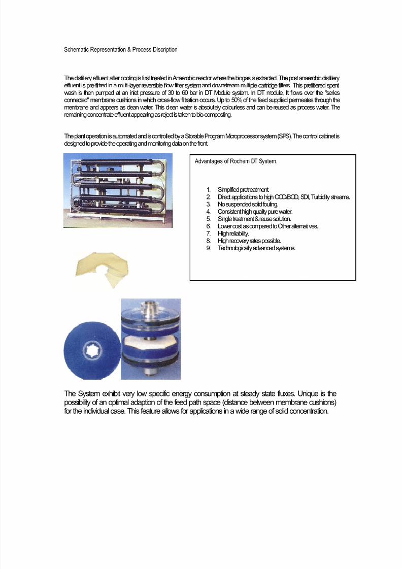
Schematic Representation & Process Discription
The distillery effluent after cooling is first treated in Anaerobic reactor where the biogas is extracted. The post anaerobic distilleryeffluent is pre-filtred in a multi-layer reversible flow filter system and downstream multiple cartridge filters. This prefiltered spentwash is then pumped at an inlet pressure of 30 to 60 bar in DT Module system. In DT module, It flows over the "seriesconnected" membrane cushions in which cross-flow filtration occurs. Up to 50% of the feed supplied permeates through themembrane and appears as clean water. This clean water is absolutely colourless and can be reused as process water. Theremaining concentrate effluent appearing as reject is taken to bio-composting.
The plant operation is automated and is controlled by a Storable Program Microprocessor system (SPS). The control cabinet isdesigned to provide the operating and monitoring data on the front.
Advantages of Rochem DT System.
1. Simplified pretreatment.2. Direct applications to high COD/BOD, SDI, Turbidity streams.3. No suspended solid fouling.4. Consistent high quality pure water.5. Single treatment & reuse solution.6. Lower cost as compared to Other alternatives.7. High reliability.8. High recovery rates possible.9. Technologically advanced systems.
The System exhibit very low specific energy consumption at steady state fluxes. Unique is thepossibility of an optimal adaption of the feed path space (distance between membrane cushions)for the individual case. This feature allows for applications in a wide range of solid concentration.
Page 25
8/19/2019 TechPaper-AnaerobicBioreactor
http://slidepdf.com/reader/full/techpaper-anaerobicbioreactor 25/26
Process Performance Parameters:
Parameter Inlet Permeate Reject
Color Blackish Brown Colorless Dark Brown
Flow 585 293 292
COD 45000 – 50000 < 1000 80000 – 90000
TDS [Inorganic] As incoming < 1250 Remaining
Recovery 50%
Budgetary Costs and Utility requirement:
Capital Investment 270.00 Rs. Lacs
Installation Land Area 275 Sq. m
Connected Load 112 kW
Operating Power Required 3 kW-hr/m3 of Feed
Preventive Maintenance cost 0.12 Rs/Lit of alcohol
Operating Power cost [approx] 0.16 Rs/Lit of alcoholManpower Cost 0.01 Rs/Lit of alcohol
TOTAL Operating Cost 0.29 Rs/Lit of alcohol
Advantages of Install ing Lars Rochem System.
• The assured annual savings after installation of system shall be approx. Rs 50.0 Lacs.
• System offers Practical Zero Discharge Solution and it is workable even in long run.
• 50 % of effluent becomes colorless.
• This colourless effluent can be recycled back into process.
• 50 % appears as reject in the form of dark brown concentrate, which can be composted.
• This system not only ensures the return of useful ingredients of spentwash to soil but at the
same time minimizes the quantity of water required for the same.
• Area required for biocomposting are reduced by almost 50 %.
Page 26
8/19/2019 TechPaper-AnaerobicBioreactor
http://slidepdf.com/reader/full/techpaper-anaerobicbioreactor 26/26
• Press mud and other input required for biocomposting are also reduced by 50 %.
• The dependency on press mud for achieving zero discharge is reduced. Hence biocomposting
can be operated even during non crushing season of sugar factory.
• The storage capacity required for press mud and treated effluent is reduced.
• Handling of treated effluent is reduced.
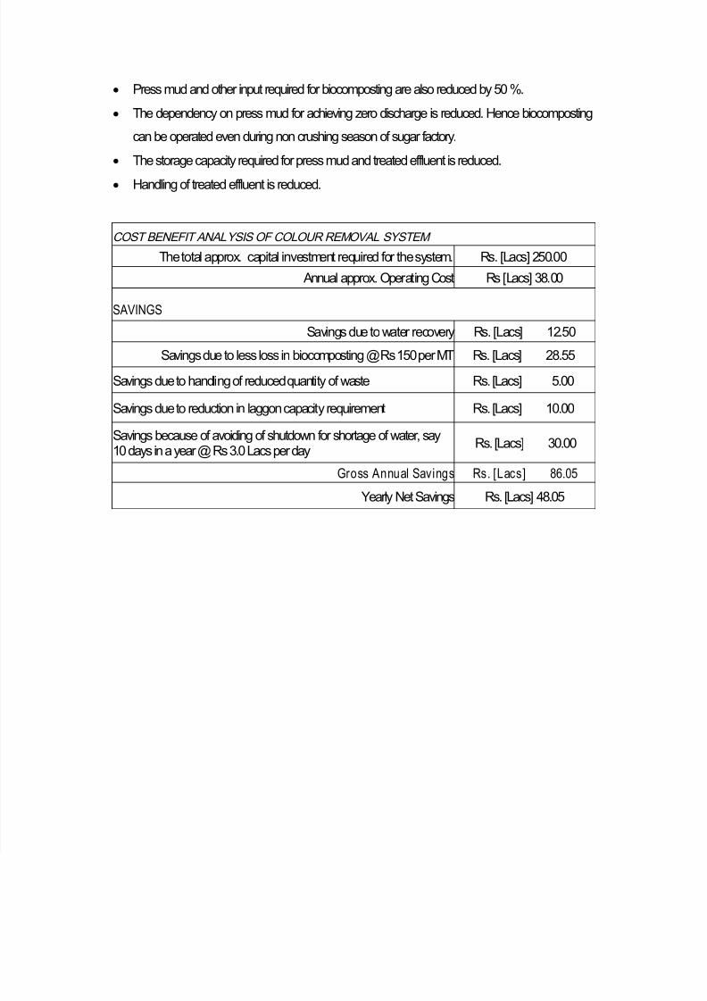
COST BENEFIT ANALYSIS OF COLOUR REMOVAL SYSTEM
The total approx. capital investment required for the system. Rs. [Lacs] 250.00
Annual approx. Operating Cost Rs [Lacs] 38.00
SAVINGS
Savings due to water recovery Rs. [Lacs] 12.50
Savings due to less loss in biocomposting @ Rs 150 per MT Rs. [Lacs] 28.55
Savings due to handling of reduced quantity of waste Rs. [Lacs] 5.00
Savings due to reduction in laggon capacity requirement Rs. [Lacs] 10.00
Savings because of avoiding of shutdown for shortage of water, say10 days in a year @ Rs 3.0 Lacs per day
Rs. [Lacs] 30.00
Gross Annual Savings Rs. [Lacs] 86.05
Yearly Net Savings Rs. [Lacs] 48.05