56
GARDNER DENVER ® 3-1-529 7 TH EDITION JUNE 2008 TRIPLEX PISTON PUMP 5” STROKE MODEL TEE PARTS LIST

GARDNER DENVER® 3-1-5297TH EDITION
JUNE 2008
TRIPLEX PISTON PUMP
5” STROKE
MODEL TEE
PARTS LIST
3-1-529 Page i
MAINTAIN PUMP RELIABILITY AND PERFORMANCE WITH GENUINE GARDNER DENVER®
PARTS AND SUPPORT SERVICES Gardner Denver® genuine pump parts are manufactured to design tolerances and are developed for optimum dependability. Design and material innovations are the result of years of experience with hundreds of different pump applications. Reliability in materials and quality assurance are incorporated in our genuine replacement parts. Your authorized Gardner Denver distributor offers all the backup you’ll need. A worldwide network of authorized distributors provides the finest product support in the pump industry. Your local authorized distributor maintains a large inventory of genuine parts and he is backed up for emergency parts issues with access to Oklahoma City, OK. and the factory in Quincy, IL. Your authorized distributor can support all your Gardner Denver pump needs. Trained parts specialists are available to assist you in selecting the correct replacement parts. ALL ORDERS for PARTS should be placed with the NEAREST Authorized Distributor. To find your nearest distributor you may use one of the following choices: * Log onto the Gardner Denver web site: www.gardnerdenver.com * Send an E-Mail request to: [email protected] * Contact one of our sales offices listed below. The Gardner Denver Sales Offices are located as follows:
DOMESTIC
INTERNATIONAL
Gardner Denver 2200 South Prospect Oklahoma City, OK. 73129
Gardner Denver 1800 Gardner Expressway Quincy, IL 62301
Phone: (405) 677-5736 Phone: (217) 222-5400 Fax: (405) 677-5807 Fax: (217) 223-1581
INSTRUCTIONS FOR ORDERING REPAIR PARTS: When ordering parts, specify Pump MODEL and SERIAL NUMBER (see nameplate on unit). The Serial Number is also stamped on top of the frame at the connecting end. (Between the cradle opening and the fluid cylinder) SPECIFY THE NUMBER OF PARTS REQUIRED, EXACTLY. DO NOT ORDER BY SETS OR GROUPS. To determine the Right Hand and Left-Hand side of a pump, stand at the power end and look toward the fluid end. Right Hand and Left Hand are indicated in parenthesis following the part name, i.e. (RH) and (LH), when appropriate.
For Operating and Service Instructions see:
SERVICE MANUAL 3-1-606

3-1-529 Page ii
TABLE OF CONTENTS Maintain Pump Reliability And Performance with Genuine Gardner Denver Parts and Support Services ..... i
Instructions For Ordering Repair Parts ............................................................................................................ i
Table of Contents............................................................................................................................................ ii
Frame Group...................................................................................................................................................1
Eccenttric, Shaft and Bearing Group ..............................................................................................................2
Oil Circulating Pump .......................................................................................................................................3
Oil Filter ...........................................................................................................................................................4
Connecting Rod ..............................................................................................................................................5
Crosshead & Oil Stop Head Group.................................................................................................................6
Oil Pump and Piping ................................................................................................................................ 7 & 8
Crosshead Lubrication Piping - LEFT HAND DRIVE......................................................................................9
Crosshead Lubrication Piping - RIGHT HAND DRIVE .................................................................................10
Fluid End - Low Pressure Cast Aluminum Bronze Cylinder (4 x 5) ..............................................................11
Fluid End - Medium Pressure Cast Aluminum Bronze Cylinder (3 x 5)........................................................12
Fluid End - High Pressure Block Steel Cylinder (2 x 5) ................................................................................13
Fluid End - High Pressure Block Steel Cylinder (4 x 5) ................................................................................14
Fluid End - High Pressure Cast Steel Cylinder (3 x 5)..................................................................................15
Stuffing Box, Plunger and Packing .................................................................................................. 16 thru 25
Piston and Liners ..........................................................................................................................................26
Delrin Disc Fluid Valves for Low Pressure Cast Aluminum Bronze Cylinder (4 x 5) ....................................27
Wing Guided Fluid Valves Low Pressure Cast Aluminum Bronze Cylinder (4 x 5) ......................................28
Delrin Disc Fluid Valves for Medium Pressure Cast Aluminum Bronze Cyl (3 x 5) ......................................29
Wing Guided Fluid Valves Medium Pressure Cast Aluminum Bronze Cyl (3 x 5)........................................30
Delrin Disc Suction Fluid Valves for High Pressure Block Steel Cylinder (2 x 5) .........................................31
Delrin Disc Discharge Fluid Valves for High Pressure Block Steel Cylinder (2 x 5) .....................................32
Wing Guided S&D Fluid Valves for High Pressure Block Steel Cylinder (2 x 5) ............................. 33 thru 36
Wing Guided S&D Fluid Valves for High Pressure Block Steel Cylinder (4 x 5) ............................. 37 thru 40
Stem Guided S&D Fluid Valves, Stainless Steel, Abrasion Resistant for High Pressure
Block Steel Cylinder (4 x 5).........................................................................................41
Wing Guided S&D Fluid Valves for High Pressure Cast Steel Cylinder (3 x 5)............................... 42 thru 44
Stem Guided S&D Fluid Valves, SS, Abrasion Resistant for High Pressure Cast Steel Cylinder (3 x 5) ....45
Lubricator Group (Optional Equipment) ........................................................................................................46
Piston Rod Wash Piping (Optional Equipment) ................................................................................... 47 & 48
Valve Seat Puller (Optional Equipment) .......................................................................................................49
Customer Repair Information........................................................................................................................50
Customer NOTES .........................................................................................................................................51
Gardner Denver Unit Record .............................................................................................. Inside Back Cover

3-1-529 Page 1
Order by Part Number and Description. Reference Numbers are shown for your convenience only.
Ref. Drawing - 301TEE810
FRAME GROUP Ref. No. Description Qty. Part No.
1 FRAME (POWER END) ......................................................... 1 304TEE001 2 INSPECTION PLATE, With Oil Manifold (Crosshead)........... 1 301TEE052
2A INSPECTION PLATE (Crosshead) ........................................ 1 302TEE052 3 SCREW, Inspection Plate ...................................................... 12 75A136 4 GASKET, Inspection Plate ..................................................... 2 25C1941 5 GASKET, Crankcase Flange.................................................. 2 25C157N 6 SCREW, Crankcase Flange................................................... 4 655ED030 7 FLANGE, Crankcase Oil Drain............................................... 2 29AUX27 8 PLUG, Crankcase Flange ...................................................... 2 64AA7 9 PLUG, Oil Level...................................................................... 2 64AA5 10 PIPE ELBOW, Oil Level ......................................................... 1 64D2 11 RETAINER PLATE (Includes next item) ................................ 1 PE1400
STUD...................................................................................... 3 79A69 12 NUT-ACORN.......................................................................... 3 50Q14 13 GASKET- COPPER, Retainer Stud Nut................................. 3 25F44 14 INSPECTION PLATE (Frame End)........................................ 1 200TEE052 15 GASKET (Frame End Inspection Plate)................................. 1 200TEE715 16 HOOD..................................................................................... 1 201TEE053 17 SCREW, Hood ....................................................................... 12 75A136 18 GASKET, Hood ...................................................................... 1 201TEE715 19 PLUG (OPPOSITE SIDE) ...................................................... 1 64B3 20 LIFTING EYE ......................................................................... 2 200TEE263 21 BREATHER............................................................................ 1 5C7 22 INSPECTION PLATE (CRADLE COVER) *........................... 1 201TEE052 23 STUD...................................................................................... 2 79A466 24 WING NUT ............................................................................. 2 50H1
* See page 50 for all cradle cover options.
3-1-529 Page 2
Order by Part Number and Description. Reference Numbers are shown for your convenience only.
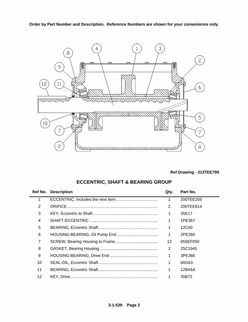
Ref Drawing - 313TEE799
ECCENTRIC, SHAFT & BEARING GROUP
Ref No. Description Qty. Part No.
1 ECCENTRIC, Includes the next item ..................................... 1 200TEE255
2 ORIFICE................................................................................. 2 200TEE814
3 KEY, Eccentric to Shaft .......................................................... 1 35K17
4 SHAFT-ECCENTRIC ............................................................. 1 1PE367
5 BEARING, Eccentric Shaft ..................................................... 1 12C60
6 HOUSING-BEARING, Oil Pump End..................................... 1 2PE266
7 SCREW, Bearing Housing to Frame...................................... 12 655EF050
8 GASKET, Bearing Housing .................................................... 2 25C1945
9 HOUSING-BEARING, Drive End ........................................... 1 3PE366
10 SEAL-OIL, Eccentric Shaft ..................................................... 1 60G63
11 BEARING, Eccentric Shaft ..................................................... 1 12BA64
12 KEY, Drive.............................................................................. 1 35B72

3-1-529 Page 3
Order by Part Number and Description. Reference Numbers are shown for your convenience only.
Ref. Drawing – 311TEE799
OIL CIRCULATING PUMP
Ref No. Description Qty. Part No. OIL CIRCULATING PUMP, Includes Ref No’s 1 thru 10 1 200PEE188
1 ROTOR ................................................................................... 1 2109376 2 BUSHING, Bracket.................................................................. 1 2118594 3 GASKET, Cover ...................................................................... 2 54C222 4 SCREW, Cover Cap................................................................ 8 2118595 5 COVER.................................................................................... 1 2109371 6 IDLER CARRIER ASSEMBLY, Includes Ref No’s 7............... 1 2109372 7 PIN, Idler ................................................................................. 1 2109373 8 GEAR, Idler ............................................................................. 1 2118596 9 BRACKET ASSEMBLY, Includes Ref No. 2 ........................... 1 2109370 10 HOUSING................................................................................ 1 2118597 11 SCREW, Housing.................................................................... 4 2118598 12 SCREW, Housing.................................................................... 4 2118599 13 NUT, Housing screw ............................................................... 4 2118600 14 SPRING, Ball........................................................................... 1 2118601 15 BALL........................................................................................ 1 2118602
The Part Numbers that are listed are for those parts that are provided for repair.

3-1-529 Page 4
Order by Part Number and Description. Reference Numbers are shown for your convenience only.
OIL FILTER
Ref No. Description Qty. Part No.
OIL FILTER ASSEMBLY, Includes next 2 items 1 26C51
1 HEAD ASSEMBLY.................................................................. 1 2118128
2 ELEMENT ............................................................................... 1 2118384

3-1-529 Page 5
Order by Part Number and Description. Reference Numbers are shown for your convenience only.
Ref. Drawing – 302TEE810
CONNECTING ROD
Ref. No. Description Qty. Part No.
1 CONNECTING ROD, Includes the next 4 items ..................... 3 PE417
2 BUSHING, Eccentric ............................................................... 3 PE421
3 BUSHING, Crosshead Pin ...................................................... 3 PE229
4 PLUG....................................................................................... 3 64AC2
5 LOCK SCREW ........................................................................ 3 75LM162N
3-1-529 Page 6
Order by Part Number and Description. Reference Numbers are shown for your convenience only.
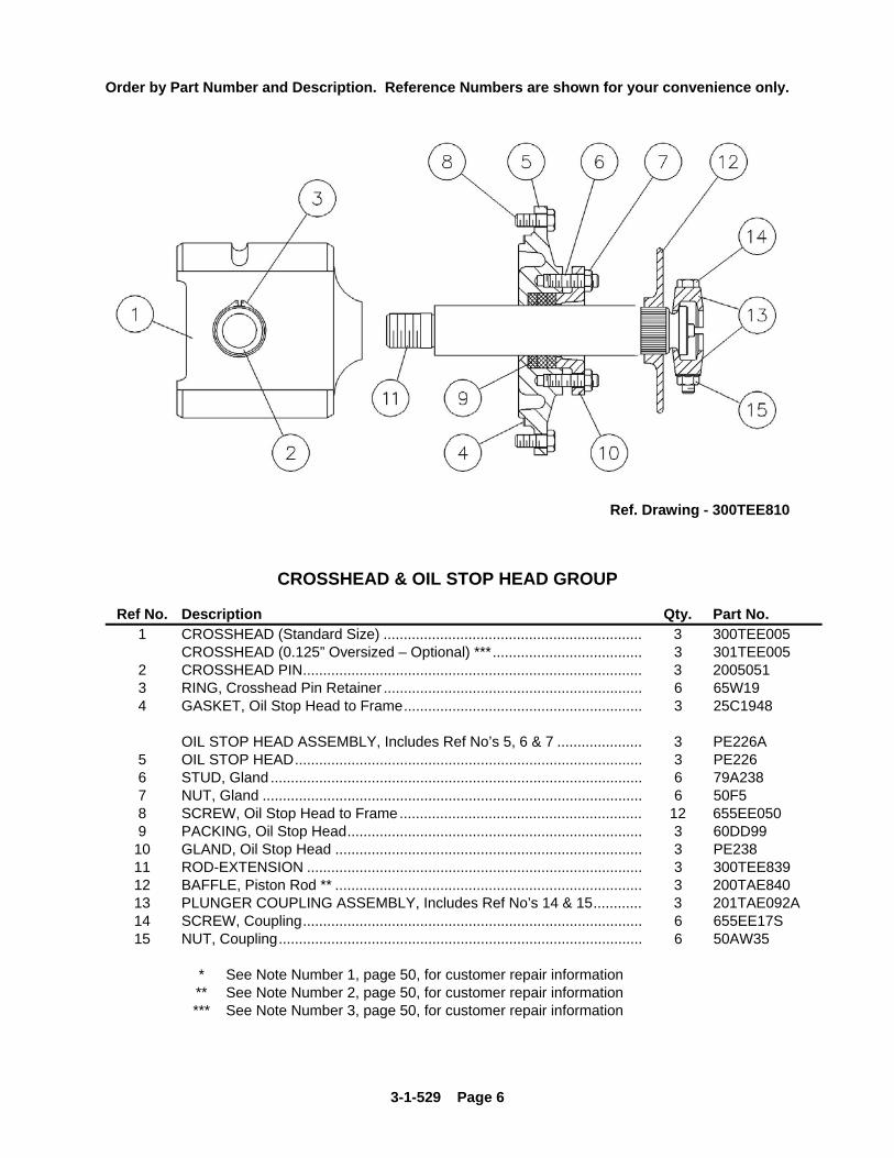
Ref. Drawing - 300TEE810
CROSSHEAD & OIL STOP HEAD GROUP
Ref No. Description Qty. Part No. 1 CROSSHEAD (Standard Size) ................................................................ 3 300TEE005 CROSSHEAD (0.125” Oversized – Optional) ***..................................... 3 301TEE005 2 CROSSHEAD PIN.................................................................................... 3 2005051 3 RING, Crosshead Pin Retainer ................................................................ 6 65W19 4 GASKET, Oil Stop Head to Frame........................................................... 3 25C1948 OIL STOP HEAD ASSEMBLY, Includes Ref No’s 5, 6 & 7 ..................... 3 PE226A 5 OIL STOP HEAD...................................................................................... 3 PE226 6 STUD, Gland ............................................................................................ 6 79A238 7 NUT, Gland .............................................................................................. 6 50F5 8 SCREW, Oil Stop Head to Frame............................................................ 12 655EE050 9 PACKING, Oil Stop Head......................................................................... 3 60DD99
10 GLAND, Oil Stop Head ............................................................................ 3 PE238 11 ROD-EXTENSION ................................................................................... 3 300TEE839 12 BAFFLE, Piston Rod ** ............................................................................ 3 200TAE840 13 PLUNGER COUPLING ASSEMBLY, Includes Ref No’s 14 & 15............ 3 201TAE092A 14 SCREW, Coupling.................................................................................... 6 655EE17S 15 NUT, Coupling.......................................................................................... 6 50AW35
* See Note Number 1, page 50, for customer repair information ** See Note Number 2, page 50, for customer repair information *** See Note Number 3, page 50, for customer repair information

OIL PUMP AND PIPING
Ref. Drawing - 303TEE810
3-1-529 Page 7

Order by Part Number and Description. Reference Numbers are shown for your convenience only.
OIL PUMP AND PIPING * For Oil Pump and Component Parts – See Page 3 ** For Oil Filter and Component Parts – See Page 4
Ref. Ref. No. Name of Part Qty. Part No. No. Name of Part Qty. Part No.
1 * OIL PUMP (Includes next item) .................... 1 200PEE188 24 HOSE ADAPTOR ....................................... 1 29Q6 2 SCREW, Oil Pump to Adaptor......................... 4 655ED190 25 PIPE BUSHING .......................................... 1 64E95 3 ** OIL FILTER ................................................. 1 26C51 26 LIQUID RELIEF VALVE.............................. 1 90Q22 4 OIL SCREEN................................................... 1 2WAJ511 27 PIPE STREET ELBOW .............................. 1 64D6 5 STUD, Connector to Frame............................. 2 79A204 28 PIPE TEE.................................................... 2 64G7 6 GASKET, Oil Drain Flange.............................. 1 25C157N 29 PIPE NIPPLE.............................................. 3 63U12X14 7 CONNECTOR ................................................. 1 200PEE284 30 PIPE BUSHING .......................................... 1 64E6 8 NUT, Connector to Frame Stud ...................... 2 50B3 31 HOSE ADAPTOR ....................................... 2 29Q16 9 PIPE NIPPLE .................................................. 1 64H4 32 HOSE ASSEMBLY ..................................... 1 29R26 10 PIPE CROSS .................................................. 1 64K18 33 PIPE PLUG................................................. 1 64A24 11 PIPE PLUG...................................................... 1 64A25 34 FILTER BRACKET...................................... 1 200TEE389 12 BUSHING ........................................................ 1 64E15 35 SCREW, Filter to Bracket ........................... 4 75LM51 13 GAUGE............................................................ 1 27H11 36 HOSE ASSEMBLY ..................................... 1 29E12 14 PIPE NIPPLE .................................................. 1 64H4 37 PIPE TEE.................................................... 1 64P78 15 CHECK VALVE ............................................... 1 300TEE308 38 GASKET, Oil Pump to Adaptor................... 1 201PEE715 16 PIPE NIPPLE .................................................. 1 304TEE126 39 ADAPTOR, Oil Pump.................................. 1 200PEE170 17 COUPLING...................................................... 1 300TEE572 40 SCREW, Adaptor to Bearing Housing ........ 6 655EE050 18 PIPE NIPPLE .................................................. 1 303TEE126 41 PRESSURE GAUGE .................................. 1 27A13 20 PIPE NIPPLE .................................................. 1 63H29 43 OIL SEAL, Main Shaft................................. 1 1PE447 21 PIPE BUSHING............................................... 1 64E7 44 PISTON RING, Oil Seal.............................. 2 65A33 22 PIPE STREET ELBOW................................... 1 64D5 45 SHIM ........................................................... 2 77G16 23 HOSE ASSEMBLY.......................................... 1 29430
3-1-529 Page 8

3-1-529 Page 9
Order by Part Number and Description. Reference Numbers are shown for your convenience only.
Ref. Drawing - 323TEE810
LEFT HAND DRIVE - CROSSHEAD LUBRICATION PIPING
Ref No. Description Qty. Part No. 1 ADAPTOR ............................................................................... 6 29Z207 2 ADAPTOR ............................................................................... 6 29Z242 3 HOSE ASSEMBLY.................................................................. 2 1000T29 4 HOSE ASSEMBLY.................................................................. 2 301TEE127 5 HOSE ASSEMBLY.................................................................. 1 1000T09 6 HOSE ASSEMBLY.................................................................. 1 30031008 7 ADAPTOR ............................................................................... 1 29Z224 8 ADAPTOR ............................................................................... 1 142635 9 PLUG....................................................................................... 1 64B3 10 HOSE ASSEMBLY.................................................................. 1 1001T55
3-1-529 Page 10
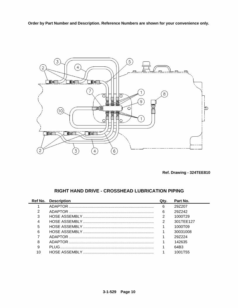
Order by Part Number and Description. Reference Numbers are shown for your convenience only.
Ref. Drawing - 324TEE810
RIGHT HAND DRIVE - CROSSHEAD LUBRICATION PIPING
Ref No. Description Qty. Part No. 1 ADAPTOR ............................................................................... 6 29Z207 2 ADAPTOR ............................................................................... 6 29Z242 3 HOSE ASSEMBLY.................................................................. 2 1000T29 4 HOSE ASSEMBLY.................................................................. 2 301TEE127 5 HOSE ASSEMBLY.................................................................. 1 1000T09 6 HOSE ASSEMBLY.................................................................. 1 30031008 7 ADAPTOR ............................................................................... 1 29Z224 8 ADAPTOR ............................................................................... 1 142635 9 PLUG....................................................................................... 1 64B3 10 HOSE ASSEMBLY.................................................................. 1 1001T55

3-1-529 Page 11
Order by Part Number and Description. Reference Numbers are shown for your convenience only.
Ref. Drawing – 314TEE799
FLUID END (TEEA) (4x5)
Low Pressure Cast Aluminum Bronze Cylinder – 4” Ref No. Description Qty. Part No.
FLUID CYLINDER ASSEMBLY, Includes Ref No’s: 1 thru 6 1 2PE29B 1 FLUID CYLINDER .................................................................................... 1 2PE29 2 STUD, Cylinder to Frame ......................................................................... 12 79AB9 3 NUT, Cylinder to Frame............................................................................ 12 50B34 4 NUT, Valve Cover Stud ............................................................................ 12 50B10 5 STUD, Valve Cover to Cylinder ................................................................ 12 79L1 6 NUT, Cylinder Stuffing Box....................................................................... 12 50B32 7 COVER-VALVE ........................................................................................ 6 3PE147 8 GASKET, Valve Cover ............................................................................. 6 25AL36 9 GASKET, Manifold to Cylinder ................................................................. 3 25AL62 10 MANIFOLD, Suction ................................................................................. 1 8PE110 11 SCREW, Manifold to Cylinder .................................................................. 12 655EF060 12 PLUG, Manifold ........................................................................................ 3 64AJ16 14 FLANGE, Suction (Steel - Threaded) ....................................................... 2 64CA13 * 15 GASKET, Flange ...................................................................................... 2 25C861N * 16 SCREW, Suction Flange .......................................................................... 16 655EG080 * 17 NUT, Flange Screw .................................................................................. 16 50B8 *
* These parts are not standard equipment, but are furnished when ordered.

3-1-529 Page 12
Order by Part Number and Description. Reference Numbers are shown for your convenience only.
Ref. Drawing – 315TEE799
FLUID END (TEEB) (3x5) Medium Pressure Cast Aluminum Bronze Cylinder – 3”
Ref No. Description Qty. Part No.
FLUID CYLINDER ASSEMBLY, Includes Ref No’s: 1 thru 6................... 1 3PE29B 1 FLUID CYLINDER ................................................................................... 1 3PE29 2 STUD, Valve Cover to Cylinder ................................................................ 24 79AJ5 3 STUD, Cylinder to Frame ......................................................................... 12 79AB16 4 NUT, Cylinder to Frame Stud ................................................................... 12 50B34 5 NUT, Cylinder Stuffing Box....................................................................... 12 50C9 6 NUT, Valve Cover Stud ............................................................................ 24 50B34 7 COVER-VALVE ........................................................................................ 6 4PE147 8 GASKET, Valve Cover ............................................................................. 6 25AL35 9 GASKET, Manifold to Cylinder ................................................................. 3 25BE27 10 MANIFOLD, Suction ................................................................................. 1 6PE110 11 SCREW, Manifold to Cylinder .................................................................. 12 655EF060 12 PLUG, Manifold ........................................................................................ 3 64AJ16 14 FLANGE, Suction (Steel - Threaded) ....................................................... 2 64CA11 * 15 GASKET, Flange ...................................................................................... 2 25C121N * 16 SCREW, Suction Flange .......................................................................... 16 655EF100 * 17 NUT, Flange Screw .................................................................................. 16 50B7 *
* These parts are not standard equipment, but are furnished when ordered.

3-1-529 Page 13
Order by Part Number and Description. Reference Numbers are shown for your convenience only.
Ref. Drawing – 316TEE799
FLUID END (TEEC) (2x5)
High Pressure Block Steel Cylinder – 2” Ref No. Description Qty. Part No.
FLUID CYLINDER ASSEMBLY, Includes Ref No’s: 1 thru 9................... 3 200PEE029B1 FLUID CYLINDER .................................................................................... 3 200PEE029 2 STUD, Cylinder to Discharge Manifold..................................................... 12 79AJ1 3 STUD, Valve Cover .................................................................................. 12 79AJ5 4 STUD, Cylinder to Frame & Stuffing Box ................................................. 12 79AK8 5 NUT, Cylinder to Discharge Manifold Stud............................................... 12 50B31 6 NUT, Valve Cover Stud ............................................................................ 12 50B34 7 NUT, Cylinder to Frame & Stuffing Box Stud ........................................... 24 50B32 8 WASHER, Cylinder to Stuffing Box .......................................................... 12 95U8 9 SPACER, Fluid Cylinder to Frame ........................................................... 6 80C44 10 COVER-VALVE ........................................................................................ 3 7PE147 11 GASKET, Valve Cover ............................................................................. 3 25AL35 12 MANIFOLD-SUCTION.............................................................................. 1 9PE110 13 SCREW, Suction Manifold to Cylinder ..................................................... 12 655EF060 14 GASKET, Suction Manifold to Cylinder .................................................... 3 25C1271N 15 PLUG, Suction Manifold ........................................................................... 3 64AA3 16 MANIFOLD-DISCHARGE ........................................................................ 1 200PEE071 17 GASKET, Cylinder to Discharge Manifold................................................ 3 25BC86 19 FLANGE, SUCTION (Steel - Threaded)................................................... 2 64CA11 * 20 GASKET, Suction Flange ......................................................................... 2 25C121N * 21 SCREW, Suction Flange .......................................................................... 16 655EF100 * 22 NUT, Suction Flange Screw ..................................................................... 16 50B7 * 23 FLANGE, Discharge Manifold (Steel – Weld Neck) ................................. 2 2009760 * 24 GASKET, Discharge Manifold Flange ...................................................... 2 2009761 * 25 SCREW, Discharge Manifold Flange ....................................................... 16 655EG180 * 26 NUT, Discharge Manifold Flange Screw .................................................. 16 50B32
* These parts are not standard equipment, but are furnished when ordered.

3-1-529 Page 14
Order by Part Number and Description. Reference Numbers are shown for your convenience only.
Ref. Drawing – 317TEE799
FLUID END (TEED & TEEE) (4x5) High Pressure Block Steel Cylinder – 4”
Ref No. Description Qty. Part No. FLUID CYLINDER ASSEMBLY, Includes Ref No’s: 1 thru 7................... 3 200TEE029B
1 FLUID CYLINDER .................................................................................... 3 200TEE029 2 STUD, Valve Cover .................................................................................. 48 201TEE110 3 STUD, Cylinder to Discharge Manifold..................................................... 12 79L96 5 NUT, Valve Cover Stud ............................................................................ 48 50B32 6 NUT, Cylinder to Discharge Manifold Stud............................................... 12 50B32 7 NUT, Cylinder to Frame Stud ................................................................... 12 50B34 8 NUT, Cylinder to Frame & Stuffing Box.................................................... 12 50AQ30 9 STUD, Cylinder to Frame & Stuffing Box ................................................. 12 200TEE110 10 COVER-VALVE, Suction .......................................................................... 3 200TEE147 11 GASKET, Valve Cover.............................................................................. 6 303TEE718 12 MANIFOLD-SUCTION.............................................................................. 1 200PEE069 13 GASKET, Suction Manifold to Cylinder .................................................... 3 25C1271N 14 SCREW, Suction Manifold to Cylinder ..................................................... 12 655EF060 15 PLUG, Suction Manifold ........................................................................... 1 64AA3 16 MANIFOLD-DISCHARGE ........................................................................ 1 200TEE071 17 GASKET, Cylinder to Discharge Manifold ................................................ 3 25AL59 18 FLANGE, Discharge (Steel – Weld Neck) ................................................ 2 64EB37 * 19 SCREW, Flange to Discharge Manifold ................................................... 16 75A231 20 NUT, Discharge Flange ............................................................................ 16 50B9 * 21 GASKET, Discharge Flange..................................................................... 2 25BC42 * 22 COVER-VALVE, Discharge...................................................................... 3 PP1005549 *
* These parts are not standard equipment, but are furnished when ordered.
3-1-529 Page 15
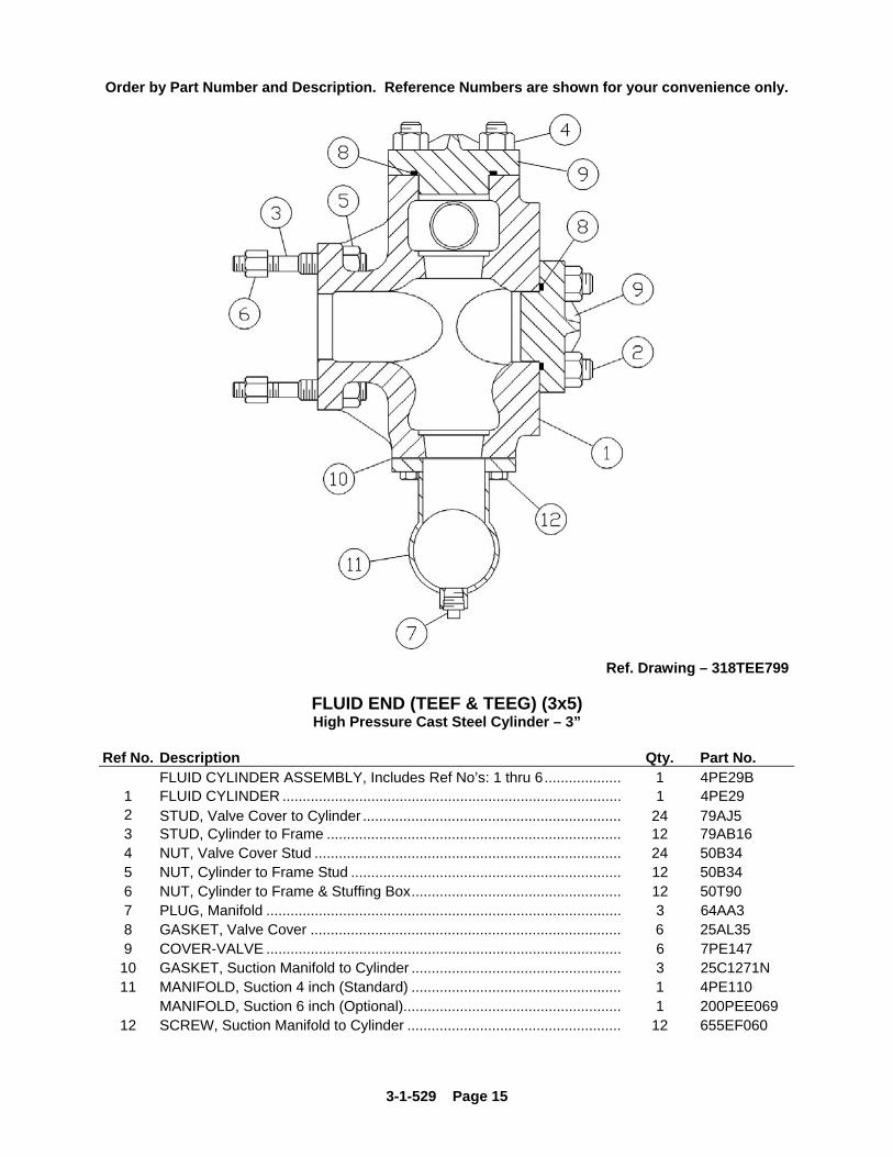
Order by Part Number and Description. Reference Numbers are shown for your convenience only.
Ref. Drawing – 318TEE799
FLUID END (TEEF & TEEG) (3x5) High Pressure Cast Steel Cylinder – 3”
Ref No. Description Qty. Part No.
FLUID CYLINDER ASSEMBLY, Includes Ref No’s: 1 thru 6................... 1 4PE29B 1 FLUID CYLINDER .................................................................................... 1 4PE29 2 STUD, Valve Cover to Cylinder ................................................................ 24 79AJ5 3 STUD, Cylinder to Frame ......................................................................... 12 79AB16 4 NUT, Valve Cover Stud ............................................................................ 24 50B34 5 NUT, Cylinder to Frame Stud ................................................................... 12 50B34 6 NUT, Cylinder to Frame & Stuffing Box.................................................... 12 50T90 7 PLUG, Manifold ........................................................................................ 3 64AA3 8 GASKET, Valve Cover ............................................................................. 6 25AL35 9 COVER-VALVE ........................................................................................ 6 7PE147 10 GASKET, Suction Manifold to Cylinder .................................................... 3 25C1271N 11 MANIFOLD, Suction 4 inch (Standard) .................................................... 1 4PE110
MANIFOLD, Suction 6 inch (Optional)...................................................... 1 200PEE069 12 SCREW, Suction Manifold to Cylinder ..................................................... 12 655EF060

3-1-529 Page 16
Order by Part Number and Description. Reference Numbers are shown for your convenience only.
Ref. Drawing – 319TEE799
STUFFING BOX, PLUNGERS & PACKING (TEEA) Low Pressure Cast Aluminum Bronze Cylinder
STYLE 838 PACKING Ref. 4.00" 3.50" 3.25" 3.00" No. Name of Part Qty. Part No. Part No. Part No. Part No. 1 GASKET ............................................. 3 25AL36 25AL36 25AL36 25AL36 2 STUFFING BOX, Includes Ref No.3 3 8PE14 9PE14 23PE14 10PE14 3 LUBE FITTING .................................... 3 40E7 40E7 40E7 40E7 STYLE 838 PACKING GROUP Includes Ref. Numbers 4 thru 7.......... 3 63PE1600 64PE1600 51PE1600 65PE1600
4 JUNK RING ........................................ 3 38PE317 36PE317 41PE317 26PE317 5 PACKING – STYLE 838 ..................... 3 60BU72 60BU73 60BU71 60BU74 6 LANTERN SPACER ............................ 3 31PE445 33PE445 28PE445 34PE445 7 GLAND BUSHING............................... 3 28PE152 29PE152 41PE152 30PE152 8 GLAND NUT........................................ 3 2PE113 2PE113 3PE113 3PE113
9 * PIN, Gland Nut tightening................... 3 62L72 62L72 62L72 62L72 10 PLUNGER (Colmonoy)........................ 3 1PE3840 1PE3835 1PE3832 302TEE038 10 PLUNGER (Ceramic) ......................... 3 PE3840 PE3835 PE3832 PE3830 10 PLUNGER (Chrome Plated)............... 3 3PE3840 3PE3835 3PE3832 3PE3830
STYLE 858 PACKING
Ref. 4.00" 3.50" 3.25" 3.00" No. Name of Part Qty. Part No. Part No. Part No. Part No. 1 GASKET ............................................. 3 25AL36 25AL36 25AL36 25AL36 2 STUFFING BOX, Includes Ref No.3 3 8PE14 9PE14 23PE14 10PE14 3 LUBE FITTING .................................... 3 40E7 40E7 40E7 40E7 STYLE 858 PACKING GROUP Includes Ref. Numbers 4 thru 7.......... 3 300TEE4060 301TEE4060 302TEE4060 303TEE4060
4 JUNK RING ........................................ 3 38PE317 36PE317 41PE317 26PE317 5 PACKING – STYLE 858 ..................... 3 60DD763 60DD761 60DD760 60DD759 6 LANTERN SPACER ............................ 3 31PE445 33PE445 28PE445 34PE445 7 GLAND BUSHING............................... 3 28PE152 29PE152 41PE152 30PE152 8 GLAND NUT........................................ 3 2PE113 2PE113 3PE113 3PE113
9 * PIN, Gland Nut tightening................... 3 62L72 62L72 62L72 62L72 10 PLUNGER (Colmonoy)........................ 3 1PE3840 1PE3835 1PE3832 302TEE038 10 PLUNGER (Ceramic) ......................... 3 PE3840 PE3835 PE3832 PE3830 10 PLUNGER (Chrome Plated)............... 3 3PE3840 3PE3835 3PE3832 3PE3830
* Not shown

3-1-529 Page 17
Order by Part Number and Description. Reference Numbers are shown for your convenience only.
Ref. Drawing – 319TEE799
STUFFING BOX, PLUNGERS & PACKING (TEEB) Medium Pressure Cast Aluminum Bronze Cylinder
STYLE 838 PACKING Ref. 3.00" 2.75" 2.50" 2.25" No. Name of Part Qty. Part No. Part No. Part No. Part No. 1 GASKET ............................................. 3 25AL36 25AL35 25AL35 25AL35 2 STUFFING BOX, Includes Ref No.3 3 10PE14 11PE14 12PE14 13PE14 3 LUBE FITTING .................................... 3 40E7 40E7 40E7 40E7 STYLE 838 PACKING GROUP Includes Ref. Numbers 4 thru 7.......... 3 65PE1600 66PE1600 67PE1600 68PE1600
4 JUNK RING ........................................ 3 26PE317 27PE317 28PE317 25PE317 5 PACKING – STYLE 838 ..................... 3 60BU74 60BU75 60BU76 60BU77 6 LANTERN SPACER ............................ 3 34PE445 35PE445 36PE445 37PE445 7 GLAND BUSHING............................... 3 30PE152 31PE152 32PE152 27PE152 8 GLAND NUT........................................ 3 3PE113 3PE113 3PE113 3PE113
9 * PIN, Gland Nut tightening................... 3 62L72 62L72 62L72 62L72 10 PLUNGER (Colmonoy)........................ 3 302TEE038 1PE3827 1PE3825 1PE3822 10 PLUNGER (Ceramic) ......................... 3 PE3830 PE3827 PE3825 PE3822 10 PLUNGER (Chrome Plated)............... 3 3PE3830 3PE3827 3PE3825 3PE3822
STYLE 858 PACKING
Ref. 3.00" 2.75" 2.50" 2.25" No. Name of Part Qty. Part No. Part No. Part No. Part No. 1 GASKET ............................................. 3 25AL36 25AL35 25AL35 25AL35 2 STUFFING BOX, Includes Ref No.3 3 10PE14 11PE14 12PE14 13PE14 3 LUBE FITTING .................................... 3 40E7 40E7 40E7 40E7 STYLE 858 PACKING GROUP Includes Ref. Numbers 4 thru 7.......... 3 303TEE4060 304TEE4060 305TEE4060 306TEE4060
4 JUNK RING ........................................ 3 26PE317 27PE317 28PE317 25PE317 5 PACKING – STYLE 858 ..................... 3 60DD759 60DD758 60DD757 60DD756 6 LANTERN SPACER ............................ 3 34PE445 35PE445 36PE445 37PE445 7 GLAND BUSHING............................... 3 30PE152 31PE152 32PE152 27PE152 8 GLAND NUT........................................ 3 3PE113 3PE113 3PE113 3PE113
9 * PIN, Gland Nut tightening................... 3 62L72 62L72 62L72 62L72 10 PLUNGER (Colmonoy)........................ 3 302TEE038 1PE3827 1PE3825 1PE3822 10 PLUNGER (Ceramic) ......................... 3 PE3830 PE3827 PE3825 PE3822 10 PLUNGER (Chrome Plated)............... 3 3PE3830 3PE3827 3PE3825 3PE3822
* Not shown

3-1-529 Page 18
Order by Part Number and Description. Reference Numbers are shown for your convenience only.
Ref. Drawing – 319TEE799
STUFFING BOX, PLUNGERS & PACKING (TEEC) 3 Piece High Pressure Block Steel Cylinder
STYLE 838 PACKING Ref. 2.00" 1.75" 1.50" No. Name of Part Qty. Part No. Part No. Part No. 1 GASKET............................................. 3 25BD3 25BD3 25BD3 2 STUFFING BOX, Includes Ref No.3 3 34PE14 35PE14 35PE14 3 LUBE FITTING.................................... 3 40E7 40E7 40E7 STYLE 838 PACKING GROUP Includes Ref. Numbers 4 thru 7 ......... 3 PS160020 PS160017 PS160015
4 JUNK RING ........................................ 3 PQ31720 PQ31717 PQ31715 5 PACKING – STYLE 838..................... 3 60BU97 60BU31 60BU98 6 LANTERN SPACER............................ 3 PQ44520 PQ44517 PQ44515 7 GLAND BUSHING............................... 3 PS15220 PS15217 PS15215 8 GLAND NUT........................................ 3 2011555 2011555 2011555
9 * PIN, Gland Nut tightening .................. 3 62L45 62L45 62L45 10 PLUNGER (Colmonoy) ....................... 3 11PE3820 11PE3817 11PE3815 10 PLUNGER (Tungsten Carbide).......... 3 200TEE038 202TEE038 204TEE038
STYLE 858 PACKING
Ref. 2.00" 1.75" 1.50" No. Name of Part Qty. Part No. Part No. Part No. 1 GASKET............................................. 3 25BD3 25BD3 25BD3 2 STUFFING BOX, Includes Ref No.3 3 34PE14 35PE14 35PE14 3 LUBE FITTING.................................... 3 40E7 40E7 40E7 STYLE 858 PACKING GROUP Includes Ref. Numbers 4 thru 7 ......... 3 307TEE4060 308TEE4060 309TEE4060
4 JUNK RING ........................................ 3 PQ31720 PQ31717 PQ31715 5 PACKING – STYLE 858..................... 3 60DD768 60DD754 60DD766 6 LANTERN SPACER............................ 3 PQ44520 PQ44517 PQ44515 7 GLAND BUSHING............................... 3 PS15220 PS15217 PS15215 8 GLAND NUT........................................ 3 2011555 2011555 2011555
9 * PIN, Gland Nut tightening .................. 3 62L45 62L45 62L45 10 PLUNGER (Colmonoy) ....................... 3 11PE3820 11PE3817 11PE3815 10 PLUNGER (Tungsten Carbide).......... 3 200TEE038 202TEE038 204TEE038
* Not shown

3-1-529 Page 19
Order by Part Number and Description. Reference Numbers are shown for your convenience only.
Ref. Drawing – 319TEE799
STUFFING BOX, PLUNGERS & PACKING (TEEC) 3 Piece High Pressure Block Steel Cylinder
STYLE 838 PACKING
Ref. 1.25" No. Name of Part Qty. Part No. 1 GASKET .............................................. 3 25BD3 2 STUFFING BOX, Includes Ref No.3 3 36PE14 3 LUBE FITTING.................................... 3 40E7 STYLE 838 PACKING GROUP Includes Ref. Numbers 4 thru 7 ........... 3 PS160012
4 JUNK RING.......................................... 3 PQ31712 5 PACKING – STYLE 838 ...................... 3 60BU33 6 LANTERN SPACER ........................... 3 PQ44512 7 GLAND BUSHING .............................. 3 PS15212 8 GLAND NUT ....................................... 3 2011555
9 * PIN, Gland Nut tightening .................... 3 62L45 10 PLUNGER (Colmonoy)....................... 3 11PE3812 10 PLUNGER (Tungsten Carbide) ........... 3 206TEE038
STYLE 858 PACKING
Ref. 1.25" No. Name of Part Qty. Part No. 1 GASKET .............................................. 3 25BD3 2 STUFFING BOX, Includes Ref No.3 3 36PE14 3 LUBE FITTING.................................... 3 40E7 STYLE 858 PACKING GROUP Includes Ref. Numbers 4 thru 7 ........... 3 310TEE4060
4 JUNK RING.......................................... 3 PQ31712 5 PACKING – STYLE 858 ...................... 3 60DD752 6 LANTERN SPACER ........................... 3 PQ44512 7 GLAND BUSHING .............................. 3 PS15212 8 GLAND NUT ....................................... 3 2011555
9 * PIN, Gland Nut tightening .................... 3 62L45 10 PLUNGER (Colmonoy)....................... 3 11PE3812 10 PLUNGER (Tungsten Carbide) ........... 3 206TEE038
* Not shown

3-1-529 Page 20
Order by Part Number and Description. Reference Numbers are shown for your convenience only.
Ref. Drawing – 319TEE799
STUFFING BOX, PLUNGERS & PACKING (TEED) 3 Piece High Pressure Block Steel Cylinder
STYLE 838 PACKING Ref. 4.00" 3.50" 3.00" 2.75" No. Name of Part Qty. Part No. Part No. Part No. Part No. 1 GASKET ............................................. 3 303TEE718 303TEE718 303TEE718 303TEE718 2 STUFFING BOX, Includes Ref No.3 3 200TEE014 201TEE014 202TEE014 203TEE014 3 LUBE FITTING .................................... 3 40E7 40E7 40E7 40E7 STYLE 838 PACKING GROUP Includes Ref. Numbers 4 thru 7.......... 3 63PE1600 64PE1600 65PE1600 66PE1600
4 JUNK RING ........................................ 3 38PE317 36PE317 26PE317 27PE317 5 PACKING – STYLE 838 ..................... 3 60BU72 60BU73 60BU74 60BU75 6 LANTERN SPACER ............................ 3 31PE445 33PE445 34PE445 35PE445 7 GLAND BUSHING............................... 3 28PE152 29PE152 30PE152 31PE152 8 GLAND NUT........................................ 3 200PEE008 200PEE008 4PE113 4PE113
9 * PIN, Gland Nut tightening................... 3 62L72 62L72 62L72 62L72 10 PLUNGER (Colmonoy)........................ 3 1PE3840 1PE3835 302TEE038 1PE3827 10 PLUNGER (Ceramic) ......................... 3 PE3840 PE3835 PE3830 PE3827 10 PLUNGER (Chrome Plated)............... 3 3PE3840 3PE3835 3PE3830 3PE3827
STYLE 838 PACKING
Ref. 2.50" 2.25" 2.00" 1.75" No. Name of Part Qty. Part No. Part No. Part No. Part No. 1 GASKET ............................................. 3 303TEE718 303TEE718 303TEE718 303TEE718 2 STUFFING BOX, Includes Ref No.3 3 204TEE014 205TEE014 206TEE014 207TEE014 3 LUBE FITTING .................................... 3 40E7 40E7 40E7 40E7 STYLE 838 PACKING GROUP Includes Ref. Numbers 4 thru 7.......... 3 67PE1600 68PE1600 69PE1600 70PE1600
4 JUNK RING ........................................ 3 28PE317 25PE317 29PE317 30PE317 5 PACKING – STYLE 838 ..................... 3 60BU76 60BU77 60BU78 60BU79 6 LANTERN SPACER ............................ 3 36PE445 37PE445 38PE445 39PE445 7 GLAND BUSHING............................... 3 32PE152 27PE152 33PE152 34PE152 8 GLAND NUT........................................ 3 4PE113 4PE113 4PE113 4PE113
9 * PIN, Gland Nut tightening................... 3 62L72 62L72 62L72 62L72 10 PLUNGER (Colmonoy)........................ 3 1PE3825 1PE3822 1PE3820 1PE3817 10 PLUNGER (Ceramic) ......................... 3 PE3825 PE3822 PE3820 PE3817 10 PLUNGER (Chrome Plated)............... 3 3PE3825 3PE3822 3PE3820 3PE3817
* Not shown

3-1-529 Page 21
Order by Part Number and Description. Reference Numbers are shown for your convenience only.
Ref. Drawing – 320TEE799
STUFFING BOX, PLUNGERS & PACKING (TEED) 3 Piece High Pressure Block Steel Cylinder
STYLE 1067 PACKING Ref. 4.00" 3.50" 3.00" 2.75" No. Name of Part Qty. Part No. Part No. Part No. Part No. 1 GASKET ............................................. 3 303TEE718 303TEE718 303TEE718 303TEE718 2 STUFFING BOX, Includes Ref No.3 3 200TEE014 201TEE014 202TEE014 203TEE014 3 LUBE FITTING .................................... 3 40E7 40E7 40E7 40E7 STYLE 1067 PACKING GROUP Includes Ref. Numbers 4 thru 7.......... 3 TEE77906 TEE77907 TEE77908 TEE77909
4 JUNK RING ........................................ 3 200TEE317 201TEE317 202TEE317 203TEE317 5 PACKING – STYLE 1067................... 3 60DD116 60DD115 60DD113 60DD112 6 LANTERN SPACER ............................ 3 200TEE445 201TEE445 202TEE445 203TEE445 7 GLAND BUSHING............................... 3 200TEE152 201TEE152 202TEE152 203TEE152 8 GLAND NUT........................................ 3 200PEE008 200PEE008 4PE113 4PE113
9 * PIN, Gland Nut tightening................... 3 62L72 62L72 62L72 62L72 10 PLUNGER (Colmonoy)........................ 3 1PE3840 1PE3835 302TEE038 1PE3827 10 PLUNGER (Ceramic) ......................... 3 PE3840 PE3835 PE3830 PE3827 10 PLUNGER (Chrome Plated)............... 3 3PE3840 3PE3835 3PE3830 3PE3827
STYLE 1067 PACKING
Ref. 2.50" 2.25" 2.00" 1.75" No. Name of Part Qty. Part No. Part No. Part No. Part No. 1 GASKET ............................................. 3 303TEE718 303TEE718 303TEE718 303TEE718 2 STUFFING BOX, Includes Ref No.3 3 204TEE014 205TEE014 206TEE014 207TEE014 3 LUBE FITTING .................................... 3 40E7 40E7 40E7 40E7 STYLE 1067 PACKING GROUP Includes Ref. Numbers 4 thru 7.......... 3 TEE77910 TEE77911 TEE77912 TEE77913
4 JUNK RING ........................................ 3 204TEE317 205TEE317 206TEE317 207TEE317 5 PACKING – STYLE 1067................... 3 60DD111 60DD110 60DD109 60DD108 6 LANTERN SPACER ............................ 3 204TEE445 205TEE445 206TEE445 207TEE445 7 GLAND BUSHING............................... 3 204TEE152 205TEE152 206TEE152 207TEE152 8 GLAND NUT........................................ 3 4PE113 4PE113 4PE113 4PE113
9 * PIN, Gland Nut tightening................... 3 62L72 62L72 62L72 62L72 10 PLUNGER (Colmonoy)........................ 3 1PE3825 1PE3822 1PE3820 1PE3817 10 PLUNGER (Ceramic) ......................... 3 PE3825 PE3822 PE3820 PE3817 10 PLUNGER (Chrome Plated)............... 3 3PE3825 3PE3822 3PE3820 3PE3817
* Not shown

3-1-529 Page 22
Order by Part Number and Description. Reference Numbers are shown for your convenience only.
Ref. Drawing – 319TEE799
STUFFING BOX, PLUNGERS & PACKING (TEED) 3 Piece High Pressure Block Steel Cylinder
STYLE 858 PACKING Ref. 4.00" 3.50" 3.00" 2.75" No. Name of Part Qty. Part No. Part No. Part No. Part No. 1 GASKET ............................................. 3 303TEE718 303TEE718 303TEE718 303TEE718 2 STUFFING BOX, Includes Ref No.3 3 200TEE014 201TEE014 202TEE014 203TEE014 3 LUBE FITTING .................................... 3 40E7 40E7 40E7 40E7 STYLE 858 PACKING GROUP Includes Ref. Numbers 4 thru 7.......... 3 300TEE4060 301TEE4060 303TEE4060 304TEE4060
4 JUNK RING ........................................ 3 38PE317 36PE317 26PE317 27PE317 5 PACKING – STYLE 858 ..................... 3 60DD763 60DD761 60DD759 60DD758 6 LANTERN SPACER ............................ 3 31PE445 33PE445 34PE445 35PE445 7 GLAND BUSHING............................... 3 28PE152 29PE152 30PE152 31PE152 8 GLAND NUT........................................ 3 200PEE008 200PEE008 4PE113 4PE113
9 * PIN, Gland Nut tightening................... 3 62L72 62L72 62L72 62L72 10 PLUNGER (Colmonoy)........................ 3 1PE3840 1PE3835 302TEE038 1PE3827 10 PLUNGER (Ceramic) ......................... 3 PE3840 PE3835 PE3830 PE3827 10 PLUNGER (Chrome Plated)............... 3 3PE3840 3PE3835 3PE3830 3PE3827
STYLE 858 PACKING
Ref. 2.50" 2.25" 2.00" 1.75" No. Name of Part Qty. Part No. Part No. Part No. Part No. 1 GASKET ............................................. 3 303TEE718 303TEE718 303TEE718 303TEE718 2 STUFFING BOX, Includes Ref No.3 3 204TEE014 205TEE014 206TEE014 207TEE014 3 LUBE FITTING .................................... 3 40E7 40E7 40E7 40E7 STYLE 858 PACKING GROUP Includes Ref. Numbers 4 thru 7.......... 3 305TEE4060 306TEE4060 311TEE4060 312TEE4060
4 JUNK RING ........................................ 3 28PE317 25PE317 29PE317 30PE317 5 PACKING – STYLE 858 ..................... 3 60DD757 60DD756 60DD768 60DD767 6 LANTERN SPACER ............................ 3 36PE445 37PE445 38PE445 39PE445 7 GLAND BUSHING............................... 3 32PE152 27PE152 33PE152 34PE152 8 GLAND NUT........................................ 3 4PE113 4PE113 4PE113 4PE113
9 * PIN, Gland Nut tightening................... 3 62L72 62L72 62L72 62L72 10 PLUNGER (Colmonoy)........................ 3 1PE3825 1PE3822 1PE3820 1PE3817 10 PLUNGER (Ceramic) ......................... 3 PE3825 PE3822 PE3820 PE3817 10 PLUNGER (Chrome Plated)............... 3 3PE3825 3PE3822 3PE3820 3PE3817
* Not shown
3-1-529 Page 23
Order by Part Number and Description. Reference Numbers are shown for your convenience only.
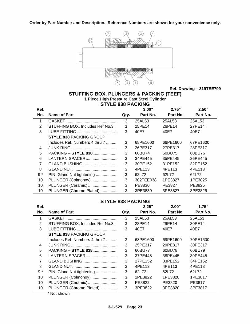
Ref. Drawing – 319TEE799
STUFFING BOX, PLUNGERS & PACKING (TEEF) 1 Piece High Pressure Cast Steel Cylinder
STYLE 838 PACKING Ref. 3.00" 2.75" 2.50" No. Name of Part Qty. Part No. Part No. Part No. 1 GASKET............................................. 3 25AL53 25AL53 25AL53 2 STUFFING BOX, Includes Ref No.3 3 25PE14 26PE14 27PE14 3 LUBE FITTING.................................... 3 40E7 40E7 40E7 STYLE 838 PACKING GROUP Includes Ref. Numbers 4 thru 7 ......... 3 65PE1600 66PE1600 67PE1600
4 JUNK RING ........................................ 3 26PE317 27PE317 28PE317 5 PACKING – STYLE 838..................... 3 60BU74 60BU75 60BU76 6 LANTERN SPACER............................ 3 34PE445 35PE445 36PE445 7 GLAND BUSHING............................... 3 30PE152 31PE152 32PE152 8 GLAND NUT........................................ 3 4PE113 4PE113 4PE113
9 * PIN, Gland Nut tightening .................. 3 62L72 62L72 62L72 10 PLUNGER (Colmonoy) ....................... 3 302TEE038 1PE3827 1PE3825 10 PLUNGER (Ceramic) ......................... 3 PE3830 PE3827 PE3825 10 PLUNGER (Chrome Plated) .............. 3 3PE3830 3PE3827 3PE3825
STYLE 838 PACKING
Ref. 2.25" 2.00" 1.75" No. Name of Part Qty. Part No. Part No. Part No. 1 GASKET............................................. 3 25AL53 25AL53 25AL53 2 STUFFING BOX, Includes Ref No.3 3 28PE14 29PE14 30PE14 3 LUBE FITTING.................................... 3 40E7 40E7 40E7 STYLE 838 PACKING GROUP Includes Ref. Numbers 4 thru 7 ......... 3 68PE1600 69PE1600 70PE1600
4 JUNK RING ........................................ 3 25PE317 29PE317 30PE317 5 PACKING – STYLE 838..................... 3 60BU77 60BU78 60BU79 6 LANTERN SPACER............................ 3 37PE445 38PE445 39PE445 7 GLAND BUSHING............................... 3 27PE152 33PE152 34PE152 8 GLAND NUT........................................ 3 4PE113 4PE113 4PE113
9 * PIN, Gland Nut tightening .................. 3 62L72 62L72 62L72 10 PLUNGER (Colmonoy) ....................... 3 1PE3822 1PE3820 1PE3817 10 PLUNGER (Ceramic) ......................... 3 PE3822 PE3820 PE3817 10 PLUNGER (Chrome Plated) .............. 3 3PE3822 3PE3820 3PE3817
* Not shown
3-1-529 Page 24
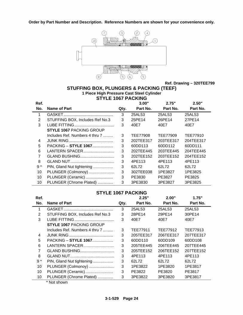
Order by Part Number and Description. Reference Numbers are shown for your convenience only.
Ref. Drawing – 320TEE799
STUFFING BOX, PLUNGERS & PACKING (TEEF) 1 Piece High Pressure Cast Steel Cylinder
STYLE 1067 PACKING Ref. 3.00" 2.75" 2.50" No. Name of Part Qty. Part No. Part No. Part No. 1 GASKET............................................. 3 25AL53 25AL53 25AL53 2 STUFFING BOX, Includes Ref No.3 3 25PE14 26PE14 27PE14 3 LUBE FITTING.................................... 3 40E7 40E7 40E7 STYLE 1067 PACKING GROUP Includes Ref. Numbers 4 thru 7 ......... 3 TEE77908 TEE77909 TEE77910
4 JUNK RING ........................................ 3 202TEE317 203TEE317 204TEE317 5 PACKING – STYLE 1067................... 3 60DD113 60DD112 60DD111 6 LANTERN SPACER............................ 3 202TEE445 203TEE445 204TEE445 7 GLAND BUSHING............................... 3 202TEE152 203TEE152 204TEE152 8 GLAND NUT........................................ 3 4PE113 4PE113 4PE113
9 * PIN, Gland Nut tightening .................. 3 62L72 62L72 62L72 10 PLUNGER (Colmonoy) ....................... 3 302TEE038 1PE3827 1PE3825 10 PLUNGER (Ceramic) ......................... 3 PE3830 PE3827 PE3825 10 PLUNGER (Chrome Plated) .............. 3 3PE3830 3PE3827 3PE3825
STYLE 1067 PACKING
Ref. 2.25" 2.00" 1.75" No. Name of Part Qty. Part No. Part No. Part No. 1 GASKET............................................. 3 25AL53 25AL53 25AL53 2 STUFFING BOX, Includes Ref No.3 3 28PE14 29PE14 30PE14 3 LUBE FITTING.................................... 3 40E7 40E7 40E7 STYLE 1067 PACKING GROUP Includes Ref. Numbers 4 thru 7 ......... 3 TEE77911 TEE77912 TEE77913
4 JUNK RING ........................................ 3 205TEE317 206TEE317 207TEE317 5 PACKING – STYLE 1067................... 3 60DD110 60DD109 60DD108 6 LANTERN SPACER............................ 3 205TEE445 206TEE445 207TEE445 7 GLAND BUSHING............................... 3 205TEE152 206TEE152 207TEE152 8 GLAND NUT........................................ 3 4PE113 4PE113 4PE113
9 * PIN, Gland Nut tightening .................. 3 62L72 62L72 62L72 10 PLUNGER (Colmonoy) ....................... 3 1PE3822 1PE3820 1PE3817 10 PLUNGER (Ceramic) ......................... 3 PE3822 PE3820 PE3817 10 PLUNGER (Chrome Plated) .............. 3 3PE3822 3PE3820 3PE3817
* Not shown

3-1-529 Page 25
Order by Part Number and Description. Reference Numbers are shown for your convenience only.
Ref. Drawing – 319TEE799
STUFFING BOX, PLUNGERS & PACKING (TEEF) 1 Piece High Pressure Cast Steel Cylinder
STYLE 858 PACKING Ref. 3.00" 2.75" 2.50" No. Name of Part Qty. Part No. Part No. Part No. 1 GASKET............................................. 3 25AL53 25AL53 25AL53 2 STUFFING BOX, Includes Ref No.3 3 25PE14 26PE14 27PE14 3 LUBE FITTING.................................... 3 40E7 40E7 40E7 STYLE 858 PACKING GROUP Includes Ref. Numbers 4 thru 7 ......... 3 303TEE4060 304TEE4060 305TEE4060
4 JUNK RING ........................................ 3 26PE317 27PE317 28PE317 5 PACKING – STYLE 858..................... 3 60DD759 60DD758 60DD757 6 LANTERN SPACER............................ 3 34PE445 35PE445 36PE445 7 GLAND BUSHING............................... 3 30PE152 31PE152 32PE152 8 GLAND NUT........................................ 3 4PE113 4PE113 4PE113
9 * PIN, Gland Nut tightening .................. 3 62L72 62L72 62L72 10 PLUNGER (Colmonoy) ....................... 3 302TEE038 1PE3827 1PE3825 10 PLUNGER (Ceramic) ......................... 3 PE3830 PE3827 PE3825 10 PLUNGER (Chrome Plated) .............. 3 3PE3830 3PE3827 3PE3825
STYLE 858 PACKING
Ref. 2.25" 2.00" 1.75" No. Name of Part Qty. Part No. Part No. Part No. 1 GASKET............................................. 3 25AL53 25AL53 25AL53 2 STUFFING BOX, Includes Ref No.3 3 28PE14 29PE14 30PE14 3 LUBE FITTING.................................... 3 40E7 40E7 40E7 STYLE 858 PACKING GROUP Includes Ref. Numbers 4 thru 7 ......... 3 306TEE4060 311TEE4060 312TEE4060
4 JUNK RING ........................................ 3 25PE317 29PE317 30PE317 5 PACKING – STYLE 858..................... 3 60DD756 60DD768 60DD767 6 LANTERN SPACER............................ 3 37PE445 38PE445 39PE445 7 GLAND BUSHING............................... 3 27PE152 33PE152 34PE152 8 GLAND NUT........................................ 3 4PE113 4PE113 4PE113
9 * PIN, Gland Nut tightening .................. 3 62L72 62L72 62L72 10 PLUNGER (Colmonoy) ....................... 3 1PE3822 1PE3820 1PE3817 10 PLUNGER (Ceramic) ......................... 3 PE3822 PE3820 PE3817 10 PLUNGER (Chrome Plated) .............. 3 3PE3822 3PE3820 3PE3817
* Not shown

3-1-529 Page 26
Order by Part Number and Description. Reference Numbers are shown for your convenience only.
Ref. Drawing - 321TEE799
PISTONS AND LINERS (TEEE) Well Service – High Pressure Block Steel – 4”
Ref. 4.00" 3.50" 3.00" 2.75" No. Name of Part Qty. Part No. Part No. Part No. Part No. 1 PISTON BODY ASSEMBLY................ 3 232TBA045A 230TBA045A 228TBA045A 227TBA045A Includes Ref No’s 2 & 3
2 O-RING................................................ 3 25AH1 25AH1 25AH1 25AH1 3 INSERT GROUP, Includes Ref. .......... 3 TBA76008 TBA76006 TBA76004 TBA76003 Numbers 4 and 5
4 PLATE-RETAINER.............................. 3 * * * * 5 RING-RETAINER ................................ 3 * * * * 6 GASKET-HYDRAULIC RING.............. 3 25AL36 25AL36 25AL36 25AL36 7 CLAMP-LINER..................................... 3 200PEE455 200PEE455 200PEE455 200PEE455 8 PISTON ROD ASM, Includes item 9 ... 3 200PEE060 200PEE060 200PEE060 200PEE060 9 NUT, Piston Rod.................................. 3 50V3 50V3 50V3 50V3 10 LINER .................................................. 3 203PEE456 202PEE456 201PEE456 200PEE456
PISTONS AND LINERS (TEEG)
Well Service – High Pressure Cast Steel – 3” Ref. 3.00" 2.75" 2.50" No. Name of Part Qty. Part No. Part No. Part No. 1 PISTON BODY ASSEMBLY ............... 3 228TBA045A 227TBA045A 45R1 Includes Ref No’s 2 & 3
2 O-RING............................................... 3 25AH1 25AH1 *** 3 INSERT GROUP, Includes Ref.......... 3 TBA76004 TBA76003 45R8 Numbers 4 and 5
4 PLATE-RETAINER.............................. 3 * * *** 5 RING-RETAINER................................ 3 * * *** 6 GASKET-HYDRAULIC RING.............. 3 25AL35 25AL35 25AL35 7 CLAMP-LINER ................................... 3 1PE217 1PE217 1PE217 8 PISTON ROD ASM, Includes item 9.. 3 200PEE060 200PEE060 200PEE060 9 NUT, Piston Rod ................................. 3 50V3 50V3 50V3 10 LINER................................................. 3 PE13930 2011248 PE13925
* Not to be sold separately *** 2, 4 and 5 are not applicable for 2.50” size

3-1-529 Page 27
Order by Part Number and Description. Reference Numbers are shown for your convenience only.
Ref Drawing - 310TEE810
DELRIN DISC FLUID VALVE LOW PRESSURE - CAST ALUMINUM BRONZE CYLINDER – 4”
SUCTION and DISCHARGE
Ref. No. Name of Part Qty. Part No. Part No. Part No.
Aluminum
Bronze Stainless Steel
Monel
FLUID VALVE ASSEMBLY 6 200VLH482 201VLH482 202VLH482 (Includes Items 1 thru 7)
1 RETAINER............................. 6 2010582 2010583 2010584 2 FASTENER............................ 6 2010598 2010598 2010598 3 PLUG-THREAD LOCK .......... 6 2010602 2010602 2010602 4 SPRING (Inner)...................... 6 2010604 2010604 2010604 5 SPRING (Outer) ..................... 6 2010607 2010607 2010607 6 VALVE DISC.......................... 6 2010611 2010611 2010611 7 VALVE SEAT ......................... 6 2010623 2010624 2010625
VALVE SEAT PULLER: Use one (1) TEE68700 Valve Puller Group & one (1) 100E6 Puller Head.

3-1-529 Page 28
Order by Part Number and Description. Reference Numbers are shown for your convenience only.
Ref Drawing - 306TEE799
WING GUIDED FLUID VALVE LOW PRESSURE - CAST ALUMINUM BRONZE CYLINDER – 4”
SUCTION and DISCHARGE ALUMINUM BRONZE – WITHOUT INSERT
Ref. No. Name of Part Qty. Part No.
FLUID VALVE ASSEMBLY.................................... 6 208VWH482A (Includes Items 1 thru 4)
1 VALVE SEAT ......................................................... 6 200VWH039 2 VALVE CAGE......................................................... 6 200VWH054 3 FLUID VALVE ........................................................ 6 3PA206 4 SPRING.................................................................. 6 78H29
VALVE SEAT PULLER: Use one (1) TEE68699 Valve Puller Group & one (1) 200PEE219 Puller Head. VALVE CAGE WRENCH: 200TEE933

3-1-529 Page 29
Order by Part Number and Description. Reference Numbers are shown for your convenience only.
Ref Drawing - 310TEE810
DELRIN DISC FLUID VALVE MEDIUM PRESSURE - CAST ALUMINUM BRONZE CYLINDER – 4”
SUCTION and DISCHARGE
Ref. No. Name of Part Qty. Part No. Part No. Part No.
Aluminum
Bronze Stainless Steel
Monel
FLUID VALVE ASSEMBLY 6 200VLF482 201VLF482 202VLF482 (Includes Items 1 thru 7)
1 RETAINER............................. 6 2010585 2010586 2010587 2 FASTENER............................ 6 2010598 2010598 2010598 3 PLUG-THREAD LOCK .......... 6 2010602 2010602 2010602 4 SPRING (Inner)...................... 6 2010605 2010605 2010605 5 SPRING (Outer) ..................... 6 2010608 2010608 2010608 6 VALVE DISC.......................... 6 2010612 2010612 2010612 7 VALVE SEAT ......................... 6 2010629 2010630 2010631
VALVE SEAT PULLER: Use one (1) TEE68700 Valve Puller Group & one (1) 100E5 Puller Head.

3-1-529 Page 30
Order by Part Number and Description. Reference Numbers are shown for your convenience only.
Ref Drawing - 307TEE799
WING GUIDED FLUID VALVE MEDIUM PRESSURE - CAST ALUMINUM BRONZE CYLINDER – 3”
SUCTION and DISCHARGE ALUMINUM BRONZE – WITHOUT INSERT
Ref. No. Name of Part Qty. Part No.
FLUID VALVE ASSEMBLY.................................... 6 208VWF482A (Includes Items 1 thru 4)
1 VALVE SEAT ......................................................... 6 200VWF039 2 VALVE CAGE......................................................... 6 200VWF054 3 FLUID VALVE ........................................................ 6 PT206 4 SPRING.................................................................. 6 78H22
VALVE SEAT PULLER: Use one (1) TEE68699 Valve Puller Group & one (1) 209TAE219 Puller Head. VALVE CAGE WRENCH: 16AUX219

3-1-529 Page 31
Order by Part Number and Description. Reference Numbers are shown for your convenience only.
Ref Drawing - 311TEE810
DELRIN DISC FLUID VALVE HIGH PRESSURE - BLOCK STEEL CYLINDER – 2”
SUCTION VALVE ONLY
Ref. No. Name of Part Qty. Part No. Part No. Part No.
Aluminum
Bronze Stainless Steel
Monel
FLUID VALVE ASSEMBLY 3 200VHC482 201VHC482 202VHC482 (Includes Items 1 thru 7)
1 RETAINER............................. 3 2010591 2010592 2010593 2 FASTENER............................ 3 2010600 2010600 2010600 3 PLUG-THREAD LOCK .......... 3 2010603 2010603 2010603 4 SPRING (Inner)...................... 3 2010606 2010606 2010606 5 SPRING (Outer) ..................... 3 2116348 2116348 2116348 6 VALVE DISC.......................... 3 2010829 2010829 2010829 7 VALVE SEAT ......................... 3 2010653 2010654 2010655
VALVE SEAT PULLER: Use one (1) TEE68699 Valve Puller Group & one (1) 205TAE219A Puller Head.

3-1-529 Page 32
Order by Part Number and Description. Reference Numbers are shown for your convenience only.
Ref Drawing - 311TEE810
DELRIN DISC FLUID VALVE HIGH PRESSURE - BLOCK STEEL CYLINDER – 2”
DISCHARGE VALVE ONLY
Ref. No. Name of Part Qty. Part No. Part No. Part No.
Aluminum
Bronze Stainless Steel
Monel
FLUID VALVE ASSEMBLY 3 210VHF482 211VHF482 212VHF482 (Includes Items 1 thru 7)
1 RETAINER............................. 3 2010588 2010828 2010590 2 FASTENER............................ 3 2010599 2010599 2010599 3 PLUG-THREAD LOCK .......... 3 2010603 2010603 2010603 4 SPRING (Inner)...................... 3 2010606 2010606 2010606 5 SPRING (Outer) ..................... 3 2116348 2116348 2116348 6 VALVE DISC.......................... 3 2010829 2010829 2010829 7 VALVE SEAT ......................... 3 2109442 2109449 2109445
VALVE SEAT PULLER: Use one (1) TEE68699 Valve Puller Group & one (1) 205TAE219A Puller Head.

3-1-529 Page 33
Order by Part Number and Description. Reference Numbers are shown for your convenience only.
Ref Drawing:
305TEE799 Ref Drawing:
307TEE799
SUCTION VALVE DISCHARGE VALVE
SUCTION VALVE WING GUIDED FLUID VALVE
HIGH PRESSURE – BLOCK STEEL CYLINDER – 2” ALUMINUM BRONZE – WITHOUT INSERT
Ref No. Name of Part Qty. Part No.
FLUID VALVE ASSEMBLY.................................... 3 208VWC482A (Includes Items 1 thru 4)
1 VALVE SEAT ......................................................... 3 200VWC039 2 VALVE CAGE......................................................... 3 200VWC054 3 FLUID VALVE ........................................................ 3 3PG206 4 SPRING.................................................................. 3 78H24
VALVE SEAT PULLER: Use one (1) TEE68699 Valve Puller Group & one (1) 208TAE219 Puller Head. VALVE CAGE WRENCH: 200TEE933
DISCHARGE VALVE WING GUIDED FLUID VALVE
HIGH PRESSURE – BLOCK STEEL CYLINDER – 2” ALUMINUM BRONZE – WITHOUT INSERT
Ref No. Name of Part Qty. Part No.
FLUID VALVE ASSEMBLY.................................... 3 208VWF482A (Includes Items 1 thru 4)
1 VALVE SEAT ......................................................... 3 200VWF039 2 VALVE CAGE......................................................... 3 200VWF054 3 FLUID VALVE ........................................................ 3 PT206 4 SPRING.................................................................. 3 78H22
VALVE SEAT PULLER: Use one (1) TEE68699 Valve Puller Group & one (1) 209TAE219 Puller Head. VALVE CAGE WRENCH: 200TEE933
3-1-529 Page 34
Order by Part Number and Description. Reference Numbers are shown for your convenience only.
Ref Drawing:
305TEE799 Ref Drawing:
302TEE799
SUCTION VALVE DISCHARGE VALVE
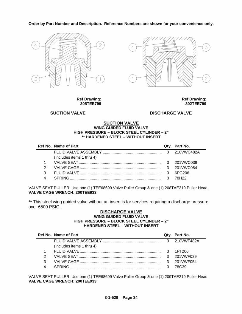
SUCTION VALVE WING GUIDED FLUID VALVE
HIGH PRESSURE – BLOCK STEEL CYLINDER – 2” ** HARDENED STEEL – WITHOUT INSERT
Ref No. Name of Part Qty. Part No.
FLUID VALVE ASSEMBLY ...................................................... 3 210VWC482A (Includes items 1 thru 4) 1 VALVE SEAT........................................................................... 3 201VWC039 2 VALVE CAGE .......................................................................... 3 201VWC054 3 FLUID VALVE.......................................................................... 3 6PG206 4 SPRING ................................................................................... 3 78H22
VALVE SEAT PULLER: Use one (1) TEE68699 Valve Puller Group & one (1) 208TAE219 Puller Head. VALVE CAGE WRENCH: 200TEE933 ** This steel wing guided valve without an insert is for services requiring a discharge pressure over 6500 PSIG.
DISCHARGE VALVE WING GUIDED FLUID VALVE
HIGH PRESSURE – BLOCK STEEL CYLINDER – 2” HARDENED STEEL – WITHOUT INSERT
Ref No. Name of Part Qty. Part No.
FLUID VALVE ASSEMBLY ...................................................... 3 210VWF482A (Includes items 1 thru 4) 1 FLUID VALVE.......................................................................... 3 1PT206 2 VALVE SEAT........................................................................... 3 201VWF039 3 VALVE CAGE .......................................................................... 3 201VWF054 4 SPRING ................................................................................... 3 78C39
VALVE SEAT PULLER: Use one (1) TEE68699 Valve Puller Group & one (1) 209TAE219 Puller Head. VALVE CAGE WRENCH: 200TEE933

3-1-529 Page 35
Order by Part Number and Description. Reference Numbers are shown for your convenience only.
Ref Drawing:
304TEE799 Ref Drawing:
303TEE799
SUCTION VALVE DISCHARGE VALVE SUCTION VALVE
WING GUIDED FLUID VALVE HIGH PRESSURE – BLOCK STEEL CYLINDER – 2”
HARDENED STEEL – WITH A REMOVABLE RUBBER INSERT
Ref No. Name of Part Qty. Part No. FLUID VALVE GROUP, Includes items 1 thru 8 ..................... 3 211VWC482A 1 FLUID VALVE ASSEMBLY, Includes items 2 thru 5 ............... 3 PG206A 2 FLUID VALVE.......................................................................... 3 PG206 3 INSERT, Rubber...................................................................... 3 PG452 4 WASHER, Retainer ................................................................. 3 95D166 5 NUT.......................................................................................... 3 50AF3 6 VALVE SEAT........................................................................... 3 201VWC039 7 SPRING ................................................................................... 3 78A148 8 VALVE CAGE .......................................................................... 3 201VWC054
VALVE SEAT PULLER: Use one (1) TEE68699 Valve Puller Group & one (1) 208TAE219 Puller Head.
VALVE CAGE WRENCH: 200TEE933 DISCHARGE VALVE
WING GUIDED FLUID VALVE HIGH PRESSURE – BLOCK STEEL CYLINDER – 2”
HARDENED STEEL – WITH A REMOVABLE RUBBER INSERT
Ref No. Name of Part Qty. Part No. FLUID VALVE GROUP, Includes items 1 thru 8 ..................... 3 211VWF482A 1 FLUID VALVE ASSEMBLY, Includes items 2 thru 5 ............... 3 1PT206C 2 FLUID VALVE.......................................................................... 3 1PT206 3 WASHER, Retainer ................................................................. 3 PT279 4 INSERT, Rubber...................................................................... 3 2PT452 5 RETAINER, Ring ..................................................................... 3 65W19 6 VALVE SEAT........................................................................... 3 201VWF039 7 SPRING ................................................................................... 3 78C39 8 VALVE CAGE .......................................................................... 3 201VWF054
VALVE SEAT PULLER: Use one (1) TEE68699 Valve Puller Group & one (1) 209TAE219 Puller Head. VALVE CAGE WRENCH: 200TEE933

3-1-529 Page 36
Order by Part Number and Description. Reference Numbers are shown for your convenience only.
Ref Drawing:
300TEE799 Ref Drawing:
301TEE799
SUCTION VALVE DISCHARGE VALVE
SUCTION VALVE
WING GUIDED FLUID VALVE HIGH PRESSURE – BLOCK STEEL CYLINDER – 2” HARDENED STEEL – WITH A MOLDED ON INSERT
Ref No. Name of Part Qty. Part No.
FLUID VALVE ASSEMBLY ...................................................... 3 VWG90867 (Includes items 1 thru 4) 1 FLUID VALVE.......................................................................... 3 215VWG482 2 VALVE SEAT........................................................................... 3 201VWC039 3 VALVE CAGE .......................................................................... 3 201VWC054 4 SPRING ................................................................................... 3 78H22
VALVE SEAT PULLER: Use one (1) TEE68699 Valve Puller Group & one (1) 208TAE219 Puller Head. VALVE CAGE WRENCH: 200TEE933
DISCHARGE VALVE
WING GUIDED FLUID VALVE
HIGH PRESSURE – BLOCK STEEL CYLINDER – 2” HARDENED STEEL – WITH A MOLDED ON INSERT
Ref No. Name of Part Qty. Part No.
FLUID VALVE ASSEMBLY ...................................................... 3 VWG90869 (Includes items 1 thru 4) 1 FLUID VALVE.......................................................................... 3 213VWG482 2 VALVE SEAT........................................................................... 3 201VWF039 3 VALVE CAGE .......................................................................... 3 201VWF054 4 SPRING ................................................................................... 3 78C39
VALVE SEAT PULLER: Use one (1) TEE68699 Valve Puller Group & one (1) 209TAE219 Puller Head. VALVE CAGE WRENCH: 200TEE933

3-1-529 Page 37
Order by Part Number and Description. Reference Numbers are shown for your convenience only.
Ref Drawing - 310TEE799
SUCTION AND DISCHARGE
WING GUIDED FLUID VALVE HIGH PRESSURE – BLOCK STEEL CYLINDER – 4”
CAST STEEL – WITHOUT INSERT
Ref. No. Name of Part Qty. Part No.
FLUID VALVE ASSEMBLY.......................................................... 6 TGE90021 (Includes Items 1 thru 4) 1 FLUID VALVE .............................................................................. 6 202TEE482 2 VALVE SEAT ............................................................................... 6 200PEE039 3 VALVE CAGE .............................................................................. 6 200PEE054 4 SPRING ....................................................................................... 6 78H26
VALVE SEAT PULLER: Use one (1) TEE73494 Valve Puller Group & one (1) 200PEE219 Puller Head. VALVE CAGE WRENCH: 200TEE933

3-1-529 Page 38
Order by Part Number and Description. Reference Numbers are shown for your convenience only.
Ref Drawing - 308TEE799
SUCTION AND DISCHARGE
WING GUIDED FLUID VALVE HIGH PRESSURE – BLOCK STEEL CYLINDER – 4”
CAST STEEL – WITH MOLDED ON INSERT (CARBOXYLATED RUBBER INSERT)
Ref. No. Name of Part Qty. Part No.
FLUID VALVE ASSEMBLY ................................................................ 6 TEE90020 (Includes Items 1 thru 4) 1 FLUID VALVE..................................................................................... 6 203TEE482 2 VALVE SEAT...................................................................................... 6 200PEE039 3 VALVE CAGE..................................................................................... 6 200PEE054 4 SPRING .............................................................................................. 6 78H26
VALVE SEAT PULLER: Use one (1) TEE73494 Valve Puller Group & one (1) 200PEE219 Puller Head. VALVE CAGE WRENCH: 200TEE933
3-1-529 Page 39
Order by Part Number and Description. Reference Numbers are shown for your convenience only.
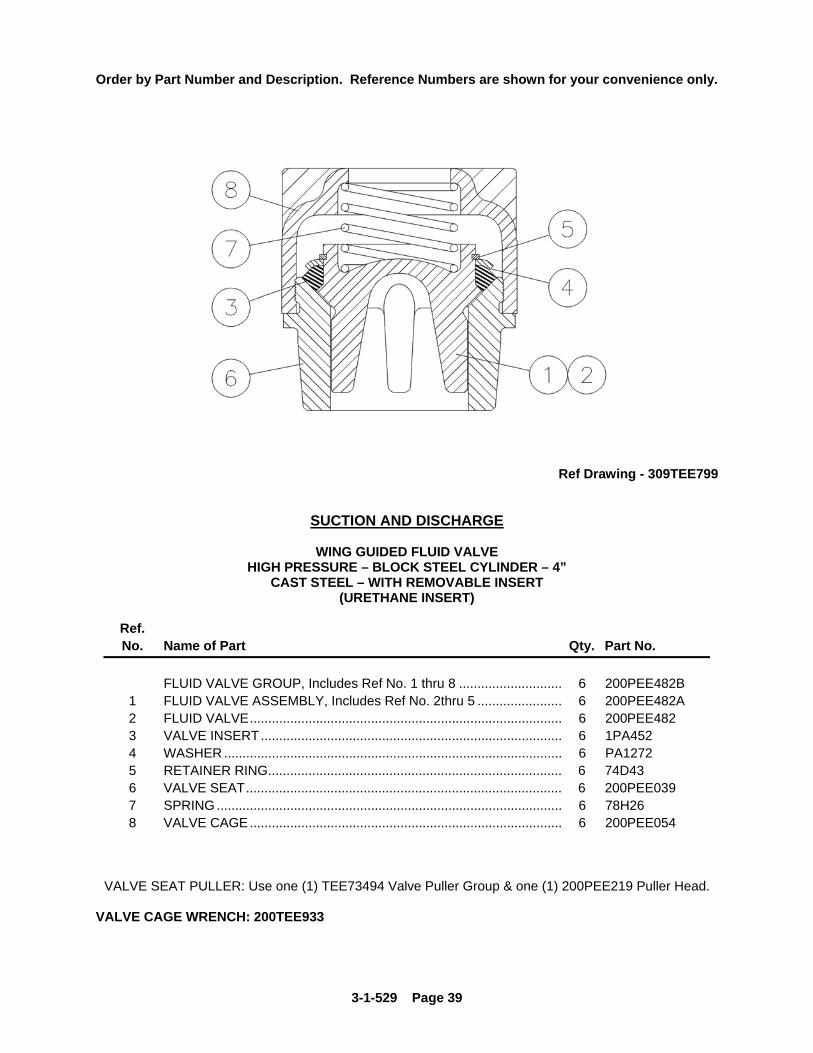
Ref Drawing - 309TEE799
SUCTION AND DISCHARGE
WING GUIDED FLUID VALVE HIGH PRESSURE – BLOCK STEEL CYLINDER – 4”
CAST STEEL – WITH REMOVABLE INSERT (URETHANE INSERT)
Ref. No. Name of Part Qty. Part No.
FLUID VALVE GROUP, Includes Ref No. 1 thru 8 ............................ 6 200PEE482B 1 FLUID VALVE ASSEMBLY, Includes Ref No. 2thru 5 ....................... 6 200PEE482A 2 FLUID VALVE..................................................................................... 6 200PEE482 3 VALVE INSERT.................................................................................. 6 1PA452 4 WASHER ............................................................................................ 6 PA1272 5 RETAINER RING................................................................................ 6 74D43 6 VALVE SEAT...................................................................................... 6 200PEE039 7 SPRING .............................................................................................. 6 78H26 8 VALVE CAGE..................................................................................... 6 200PEE054
VALVE SEAT PULLER: Use one (1) TEE73494 Valve Puller Group & one (1) 200PEE219 Puller Head. VALVE CAGE WRENCH: 200TEE933

3-1-529 Page 40
Order by Part Number and Description. Reference Numbers are shown for your convenience only.
Ref Drawing - 308TEE799
SUCTION AND DISCHARGE
WING GUIDED FLUID VALVE HIGH PRESSURE – BLOCK STEEL CYLINDER – 4”
CAST STEEL – WITH MOLDED ON INSERT (POLYURETHANE RUBBER INSERT)
Ref. No. Name of Part Qty. Part No.
FLUID VALVE ASSEMBLY ................................................................ 6 TEE90019 (Includes Items 1 thru 4) 1 FLUID VALVE..................................................................................... 6 204TEE482 2 VALVE SEAT...................................................................................... 6 200PEE039 3 VALVE CAGE..................................................................................... 6 200PEE054 4 SPRING .............................................................................................. 6 78H26
VALVE SEAT PULLER: Use one (1) TEE73494 Valve Puller Group & one (1) 200PEE219 Puller Head. VALVE CAGE WRENCH: 200TEE933

3-1-529 Page 41
Order by Part Number and Description. Reference Numbers are shown for your convenience only.
Ref Drawing - 312TEE810
SUCTION AND DISCHARGE
STAINLESS STEEL FLUID VALVE HIGH PRESSURE - BLOCK STEEL CYLINDER – 4”
ABRASION RESISTANT
Ref. No. Name of Part Qty. Part No.
FLUID VALVE ASSEMBLY ............................................................ 6 209TEE482 (Includes Items 1 thru 6)
1 VALVE SEAT.................................................................................. 6 2116687 2 O-RING........................................................................................... 6 2116520 3 VALVE INSERT.............................................................................. 6 2116521 4 VALVE, Abrasion Resistant............................................................ 6 2116522 5 SPRING .......................................................................................... 6 2116523 6 VALVE CAGE................................................................................. 6 2116524
VALVE SEAT PULLER: Use one (1) TEE73494 Valve Puller Group & one (1) 200PEE219 Puller Head. VALVE CAGE WRENCH: 200TEE933

3-1-529 Page 42
Order by Part Number and Description. Reference Numbers are shown for your convenience only.
Ref Drawing - 303TEE799
SUCTION and DISCHARGE VALVE
WING GUIDED FLUID VALVE HIGH PRESSURE – BLOCK STEEL CYLINDER – 3”
HARDENED STEEL – WITH A REMOVABLE RUBBER INSERT
Ref No. Name of Part Qty. Part No. FLUID VALVE GROUP, Includes items 1 thru 8 ..................... 6 211VWF482A 1 FLUID VALVE ASSEMBLY, Includes items 2 thru 5 ............... 6 1PT206C 2 FLUID VALVE.......................................................................... 6 1PT206 3 WASHER, Retainer ................................................................. 6 PT279 4 INSERT, Rubber...................................................................... 6 2PT452 5 RETAINER, Ring ..................................................................... 6 65W19 6 VALVE SEAT........................................................................... 6 201VWF039 7 SPRING ................................................................................... 6 78C39 8 VALVE CAGE .......................................................................... 6 201VWF054
VALVE SEAT PULLER: Use one (1) TEE68699 Valve Puller Group & one (1) 209TAE219 Puller Head. VALVE CAGE WRENCH: 200TEE933

3-1-529 Page 43
Order by Part Number and Description. Reference Numbers are shown for your convenience only.
Ref Drawing - 302TEE799
SUCTION and DISCHARGE VALVE
WING GUIDED FLUID VALVE HIGH PRESSURE – CAST STEEL CYLINDER – 3”
HARDENED STEEL – WITHOUT INSERT
Ref No. Name of Part Qty. Part No. FLUID VALVE ASSEMBLY ...................................................... 6 210VWF482A (Includes items 1 thru 4) 1 FLUID VALVE.......................................................................... 6 1PT206 2 VALVE SEAT........................................................................... 6 201VWF039 3 VALVE CAGE .......................................................................... 6 201VWF054 4 SPRING ................................................................................... 6 78C39
VALVE SEAT PULLER: Use one (1) TEE68699 Valve Puller Group & one (1) 209TAE219 Puller Head. VALVE CAGE WRENCH: 200TEE933

3-1-529 Page 44
Order by Part Number and Description. Reference Numbers are shown for your convenience only.
Ref Drawing - 301TEE799
SUCTION and DISCHARGE VALVE
WING GUIDED FLUID VALVE HIGH PRESSURE – CAST STEEL CYLINDER – 3”
HARDENED STEEL – WITH A MOLDED ON INSERT
Ref No. Name of Part Qty. Part No. FLUID VALVE ASSEMBLY ...................................................... 6 VWG90869 (Includes items 1 thru 4) 1 FLUID VALVE.......................................................................... 6 213VWG482 2 VALVE SEAT........................................................................... 6 201VWF039 3 VALVE CAGE .......................................................................... 6 201VWF054 4 SPRING ................................................................................... 6 78C39
VALVE SEAT PULLER: Use one (1) TEE68699 Valve Puller Group & one (1) 209TAE219 Puller Head. VALVE CAGE WRENCH: 200TEE933

3-1-529 Page 45
Order by Part Number and Description. Reference Numbers are shown for your convenience only.
Ref Drawing - 312TEE810
SUCTION AND DISCHARGE
STAINLESS STEEL FLUID VALVE HIGH PRESSURE - CAST STEEL CYLINDER – 3”
ABRASION RESISTANT
Ref. No. Name of Part Qty. Part No.
FLUID VALVE ASSEMBLY ............................................................ 6 208TEE482 (Includes Items 1 thru 6)
1 VALVE SEAT.................................................................................. 6 2116561 2 O-RING........................................................................................... 6 2116284 3 VALVE INSERT.............................................................................. 6 2116283 4 VALVE, Abrasion Resistant............................................................ 6 2116347 5 SPRING .......................................................................................... 6 2116348 6 VALVE CAGE................................................................................. 6 2116282
VALVE SEAT PULLER: Use one (1) TEE68699 Valve Puller Group & one (1) 209TAE219 Puller Head. VALVE CAGE WRENCH: 200TEE933

3-1-529 Page 46
Order by Part Number and Description. Reference Numbers are shown for your convenience only.
Ref. Drawing - 315TEE810
LUBRICATOR GROUP (Optional Equipment)
Ref. No. Description Qty. Part No. LUBRICATOR GROUP Includes the Following Items. 1 TEE90984
1 BRACKET, Lubricator ............................................................................... 1 200TEE403 2 SCREW, Bracket to Frame ....................................................................... 2 655EE040 3 WASHER................................................................................................... 2 95A5 4 SCREW, Bracket to Frame (Cradle Area)................................................. 2 75LM51 5 LUBRICATOR, (Ratchet Type) ................................................................. 1 40G99 6 SCREW, Lubricator to Bracket.................................................................. 4 75LM50 7 BRACKET, Lubricator Drive ...................................................................... 1 200PEE017 8 SCREW, Plunger Coupling ....................................................................... 2 655EE18Z 9 END, Control Rod...................................................................................... 1 BM11210A 10 SCREW, Rod End to Drive Bracket .......................................................... 1 655ED060 11 WASHER................................................................................................... 2 95A3 12 CONTROL ROD, Lubricator...................................................................... 1 2005879 13 LOCKNUT, Control Rod............................................................................ 1 50B3 14 CONNECTOR, Tube - 90 Degree............................................................. 3 86A25 15 TUBING, Lubricator to Stuffing boxes (Length Required for 1 Pump)...... 20 Ft. 85E4A 16 CONNECTOR, Tube - Straight ................................................................. 3 86A1 17 CHECK VALVE ......................................................................................... 3 90AR373 18 STUD, Cradle Cover ................................................................................. 2 79A466 19 WINGNUT, Cradle Cover .......................................................................... 2 50H1 20 INSPECTION PLATE, Cradle Cover......................................................... 1 202TEE052 21 SIGHT GLASS, (Included with Lubricator)................................................ 1 40P15

3-1-529 Page 47
PISTON ROD WASH PIPING (Optional Equipment)
Ref. Drawing - 313TEE810

3-1-529 Page 48
Order by Part Number and Description. Reference Numbers are shown for your convenience only.
PISTON ROD WASH PIPING (Optional Equipment)
Ref. No. Description Qty. Part No.
1 SHEAVE, Driven ....................................................................................... 1 73K1A30 2 BUSHING, Sheave.................................................................................... 1 22E16B 3 CENTRIFUGAL PUMP.............................................................................. 1 CA122 4 SCREW, Pump to Skid.............................................................................. 4 655ED040 5 LOCK WASHER........................................................................................ 4 95B3 6 WASHER................................................................................................... 4 95A3 7 NUT ........................................................................................................... 4 50B3 8 OIL SCREEN............................................................................................. 1 3WAJ511 9 PIPE REDUCER ....................................................................................... 1 64N7 10 PIPE NIPPLE ............................................................................................ 2 63H1 11 PIPE COUPLING ...................................................................................... 1 64AB4 12 ADAPTOR ................................................................................................. 2 29Q9 13 VALVE, Regulator ..................................................................................... 1 90AR299 14 PIPE NIPPLE ............................................................................................ 1 63H25 15 PIPE ELBOW, 90 Deg............................................................................... 1 64S5 16 PIPE NIPPLE ............................................................................................ 3 63G15 17 PIPE TEE .................................................................................................. 3 64P39 18 VALVE, Shut-Off ....................................................................................... 1 90A35 19 PIPE NIPPLE ............................................................................................ 2 63G1 20 PIPE COUPLING ...................................................................................... 1 64AB3 21 CLAMP, Pipe............................................................................................. 2 98H4 22 SCREW, Clamp to Frame ......................................................................... 2 655EC020 23 HYDRAULIC HOSE ASSEMBLY.............................................................. 3 29R32 24 HOSE ADAPTOR...................................................................................... 3 29Q7 25 PIPE BUSHING......................................................................................... 3 64E2 26 BAFFLE..................................................................................................... 3 200TEE840 27 TANK ASSEMBLY, Recovery (Includes the Next Item)............................ 1 PA252A
TANK COVER ........................................................................................... 1 PA253 28 SCREW, Tank to Skid ............................................................................... 4 655EE070 29 LOCK WASHER........................................................................................ 4 95B5 30 NUT ........................................................................................................... 4 50B5 31 PLUG......................................................................................................... 1 64A6 32 PLUG......................................................................................................... 1 64AA7 33 INSPECTION PLATE (Slotted Cradle Cover) ........................................... 1 304TEE052
The Following Will Be Furnished By the Customer: ........................... SHEAVE, Auxiliary Drive........................................................................... 1 BELT, Single ............................................................................................. 1 HYDRAULIC HOSE ASSEMBLY (1” with 1” fittings) ................................ 1 HYDRAULIC HOSE ASSEMBLY (1” with 1” fittings) ................................ 1 DRAIN, Return .......................................................................................... 1

3-1-529 Page 49
Order by Part Number and Description. Reference Numbers are shown for your convenience only.
Ref. Drawing - 314TEE810
Ref. No. Name of Part Qty. Part No. Part No. Part No.
VALVE SEAT PULLER GROUP ........... 1 TEE68699 TEE68700 TEE73494
(Includes Items 1 thru 6)
1 ROD....................................................... 1 200TAE193 200TEE193 200TAE193
2 PULLER PLATE .................................... 1 200TEE340 200TEE340 202TEE340
3 WASHER ............................................... 1 200TAE244 200TAE244 200TAE244
4 WEDGE ................................................. 1 200TAE091 200TAE091 200TAE091
5 WASHER ............................................... 1 95U14 95U14 95U14
6 NUT........................................................ 1 200TAE086 200TAE086 200TAE086
* INSTRUCTION TAG 1 201TAE304 201TAE304 201TAE304
* Not Shown on Illustration

3-1-529 Page 50
CUSTOMER REPAIR INFORMATION NOTE: 1. TEE Pump with a Serial Number 917132 and Later are equipped with the Two Piece
Crosshead / extension rod, as shown on page 6.
Pumps with Serial Numbers previous to 917132 have a One Piece Crosshead / Extension Rod.
For pumps with the earlier Serial Numbers, the 300TEE6005 conversion kit must be
used when a repair crosshead is required. The 300TEE6005 conversion kit includes: (1) 300TEE005 CROSSHEAD (1) 300TEE839 EXTENSION ROD (1) 200TAE840 BAFFLE 2. The PE840 Extension Rod Baffle is required for pumps that do not have the Two Piece Crosshead / Extension Rod construction. 3. Oversized Crossheads are available for pumps with Serial Numbers 917132 and later. (301TEE005) An Oversized Crosshead Conversion Kit is available for pumps that are equipped with One Piece Crosshead / Extension Rod. (301TEE6005) The 301TEE6005 conversion kit includes: (1) 301TEE005 CROSSHEAD (1) 300TEE839 EXTENSION ROD (1) 200TAE840 BAFFLE 4. Available Cradle Covers: a. 201TEE052 – Standard b. 202TEE052 – Used with Lubricator Option c. 204TEE052 – Plexiglas (See Through) d. 303TEE052 – Ventilated e. 304TEE052 – Used with Rod Wash Option 5. MODEL CYLINDER SIZE x STROKE TEEA 4 x 5 TEEB 3 x 5 TEEC 2 x 5 TEED 4 x 5 TEEE 4 x 5 TEEF 3 x 5 TEEG 3 x 5

3-1-529 Page 51
NOTES ____________________________________________________________________________ ____________________________________________________________________________ ____________________________________________________________________________ ____________________________________________________________________________ ____________________________________________________________________________ ____________________________________________________________________________ ____________________________________________________________________________ ____________________________________________________________________________ ____________________________________________________________________________ ____________________________________________________________________________ ____________________________________________________________________________ ____________________________________________________________________________ ____________________________________________________________________________ ____________________________________________________________________________ ____________________________________________________________________________ ____________________________________________________________________________ ____________________________________________________________________________ ____________________________________________________________________________ ____________________________________________________________________________ ____________________________________________________________________________ ____________________________________________________________________________ ____________________________________________________________________________

GARDNER DENVER PUMP UNIT RECORD
The following unit identification plate is provided as a convenience to you, our valued Gardner Denver customer. Please take the time to copy all the information from the actual nameplate on your unit. The model number, date manufactured and serial number will be required when contacting the company or your distributor for information or replacement parts.
Ref. Drawing – 200OPA496

For additional information contact your local distributor or Gardner Denver - Fluid Transfer Division,
1800 Gardner Expressway, Quincy, Illinois 62301 Customer Service Department Telephone:
(800) 682-9868 FAX: (217) 223-1581
For Domestic parts information Contact: Gardner Denver – Fluid Transfer Division,
2200 South Prospect, Oklahoma City, OK. 73129 Telephone: (405) 677-5736 FAX: (405) 677-5807
Specifications subject to change without notice. Copyright © 2008 Gardner Denver, Inc. DJC Litho in U.S.A.
北京
信德迈科技(北京)有限公司CNMEC Technology
北京朝阳区胜古中路2号金基业大厦201室
邮编:100029
电话:010-8428 2935 13910962635
传真:010-8428 8762
主页://www.cnmec.biz
电子邮件:[email protected]
西安
西安嘉岳自动化技术有限公司Garye Automation
地址:西安经开区凤城二路天地时代广场B座23层22312室
邮编:710016
电话:029 - 8610 8648 15319759129
传真:029 - 8610 6806
主页:http://www.garye.cn
电子邮件: [email protected]


![TEE Certification Process v1 - GlobalPlatform · [TEE EM] GPD_TEN_045 : GlobalPlatform TEE Security Target Template . Public [TEE ST] GPD_SPE_050 : GlobalPlatform TEE Common Automated](https://static.documents.pub/doc/80x56/6027a08e90016542ee50485b/tee-certification-process-v1-globalplatform-tee-em-gpdten045-globalplatform.jpg)


