Trans. Nonferrous Met. Soc. China 26(2016) 213−227 Teflon-pad shaping process of circular metal blanks into quasi-cup specimens by theoretical and experimental methods Abbas NIKNEJAD, Iman KARAMI FATH Mechanical Engineering Department, Yasouj University, P. O. Box 75914-353 Yasouj, Iran Received 20 February 2015; accepted 20 October 2015 Abstract: Teflon-pad shaping process of circular metal blanks into quasi-cup specimens is investigated by theoretical and experimental methods in the quasi-static condition. In the experiments, circular metal sheets are formed into the quasi-cup samples by compressing them between a Teflon-filled die and a rigid punch with desirable shape. To investigate influences of different parameters on the forming progress, 12 rigid punches with different dimensions, two blank material types of aluminum and galvanized iron, three blank thicknesses of 0.6, 1.1 and 1.5 mm, and two Teflon-fillers of PVC and polyurethane are used in several experimental tests. In the analytical part, theoretical deformation models of metal blank and Teflon-filler are introduced and based on energy method, energy absorptions by the blank and Teflon-filler are calculated to derive a theoretical formula for predicting total required energy of the forming process. For this purpose, several energy absorption mechanisms are considered in the blank and filler. Furthermore, predictions by theoretical equation are compared with the corresponding experimental tests to study the verity of the calculated formulas. Theoretical and experimental results illustrate change trend of forming energy with respect to blank thickness. Also, the performed forming tests show that when external cone angle of rigid punch with respect to the horizontal direction increases, forming energy increases nonlinearly; and when the depth of spherical part of rigid punch increases, the probability of rupture increases. Additionally, the experiments demonstrate that there is a direct relationship between the forming energy and flow stress of the blanks. Furthermore, experimental observations illustrate that forming energy of a certain blank with PVC Teflon-filler is higher than that of a similar specimen with polyurethane Teflon-filler; but, the probability of wrinkling decreases when PVC Teflon-pad is used as the filler; and it is advantage of PVC Teflon-filler with respect to polyurethane Teflon. Key words: Teflon-pad forming; circular metal blank; quasi-cup specimen; PVC Teflon-filler; polyurethane Teflon-filler; forming energy 1 Introduction Innovations introduced in metal forming processes during the last 50 years can be placed in several categories. These include the use of unconventional tools such as those using high hydraulic pressure, flexible tools, the use of both fluid and solid friction to aid forming, and techniques such as experimental and finite element analysis of forming problems. Flexible tool materials such as polyurethane and rubber are being used increasingly in the design of metal forming tools [1]. THIRUVARUDCHELVAN [1] discussed several novel applications of urethane in the design of metal forming tools. RAMEZANI et al [2] presented a theoretical approach to model the static and kinetic friction in rubber-pad forming process that considered local contact conditions and to evaluate influences of friction models on finite element results. FE simulations were carried out using commercial software ABAQUS/ Standard for an axisymmetric rubber-pad forming operation using the defined friction models. Experiments of rubber-pad forming were also carried out using natural rubber as the flexible punch. The results of finite element simulations using the defined friction models were compared with the experimental results [2]. Wrinkling is a common failure in the sheet metal forming. It is important to predict wrinkling accurately in the sheet metal forming without costly trials [3]. SUN et al [3] predicted wrinkling and influence of rubber hardness on the winkling behavior in the rubber forming of convex flange and the predictions were validated by experimental results of rubber forming process. BROWNE and BATTIKHA [4] represented an experimental study of the rubber-pad forming process, which was used widely to produce aerospace and Corresponding author: Abbas NIKNEJAD; Tel: +98-74-33229889; Fax: +98-74-33221711; E-mail: [email protected]DOI: 10.1016/S1003-6326(15)64061-4
Transcript
Trans. Nonferrous Met. Soc. China 26(2016) 213−227
Teflon-pad shaping process of circular metal blanks into
quasi-cup specimens by theoretical and experimental methods
Abbas NIKNEJAD, Iman KARAMI FATH
Mechanical Engineering Department, Yasouj University, P. O. Box 75914-353 Yasouj, Iran
Received 20 February 2015; accepted 20 October 2015
Abstract: Teflon-pad shaping process of circular metal blanks into quasi-cup specimens is investigated by theoretical and experimental methods in the quasi-static condition. In the experiments, circular metal sheets are formed into the quasi-cup samples by compressing them between a Teflon-filled die and a rigid punch with desirable shape. To investigate influences of different parameters on the forming progress, 12 rigid punches with different dimensions, two blank material types of aluminum and galvanized iron, three blank thicknesses of 0.6, 1.1 and 1.5 mm, and two Teflon-fillers of PVC and polyurethane are used in several experimental tests. In the analytical part, theoretical deformation models of metal blank and Teflon-filler are introduced and based on energy method, energy absorptions by the blank and Teflon-filler are calculated to derive a theoretical formula for predicting total required energy of the forming process. For this purpose, several energy absorption mechanisms are considered in the blank and filler. Furthermore, predictions by theoretical equation are compared with the corresponding experimental tests to study the verity of the calculated formulas. Theoretical and experimental results illustrate change trend of forming energy with respect to blank thickness. Also, the performed forming tests show that when external cone angle of rigid punch with respect to the horizontal direction increases, forming energy increases nonlinearly; and when the depth of spherical part of rigid punch increases, the probability of rupture increases. Additionally, the experiments demonstrate that there is a direct relationship between the forming energy and flow stress of the blanks. Furthermore, experimental observations illustrate that forming energy of a certain blank with PVC Teflon-filler is higher than that of a similar specimen with polyurethane Teflon-filler; but, the probability of wrinkling decreases when PVC Teflon-pad is used as the filler; and it is advantage of PVC Teflon-filler with respect to polyurethane Teflon. Key words: Teflon-pad forming; circular metal blank; quasi-cup specimen; PVC Teflon-filler; polyurethane Teflon-filler; forming energy 1 Introduction
Innovations introduced in metal forming processes during the last 50 years can be placed in several categories. These include the use of unconventional tools such as those using high hydraulic pressure, flexible tools, the use of both fluid and solid friction to aid forming, and techniques such as experimental and finite element analysis of forming problems. Flexible tool materials such as polyurethane and rubber are being used increasingly in the design of metal forming tools [1].
THIRUVARUDCHELVAN [1] discussed several novel applications of urethane in the design of metal forming tools. RAMEZANI et al [2] presented a theoretical approach to model the static and kinetic friction in rubber-pad forming process that considered local contact conditions and to evaluate influences of
friction models on finite element results. FE simulations were carried out using commercial software ABAQUS/ Standard for an axisymmetric rubber-pad forming operation using the defined friction models. Experiments of rubber-pad forming were also carried out using natural rubber as the flexible punch. The results of finite element simulations using the defined friction models were compared with the experimental results [2].
Wrinkling is a common failure in the sheet metal forming. It is important to predict wrinkling accurately in the sheet metal forming without costly trials [3]. SUN et al [3] predicted wrinkling and influence of rubber hardness on the winkling behavior in the rubber forming of convex flange and the predictions were validated by experimental results of rubber forming process. BROWNE and BATTIKHA [4] represented an experimental study of the rubber-pad forming process, which was used widely to produce aerospace and
Abbas NIKNEJAD, et al/Trans. Nonferrous Met. Soc. China 26(2016) 213−227
214
automotive parts. They indicated some advantages of the rubber-pad forming process as follows: only one rigid tool half is required to form a part; parts with excellent surface finish can be formed as no surface tool marks are created; thinning of the work piece is reduced considerably; and different metals with various thicknesses can be formed using the same tooling. SUN et al [5] experimentally investigated effects of different punch and rubber hardness on the limit principal strain distributions. They established finite element analysis models of samples to analyze friction coefficients of different interfaces and studied effects of various friction coefficients on the strain distributions in detail. THIRUVARUDCHELVAN [6] presented brief survey of several uses of elastomers such as urethane in metal forming and described properties of flexible tool materials (urethane) during the process. He considered elastic modulus and friction characteristic of urethane which are needed for calculations. AL-QURESHI [7] investigated feasibility of elastomer forming for the simultaneous forming, embossing and shearing of sheet metals to produce special panels. In his work, the confined system was adopted, where the elastomer was housed in a container. Also, a simplified analytical treatment was presented for predicting the applied load and total ram movement required for the forming process. THIRUVARUDCHELVAN [8] introduced a urethane clamp that is able to generate a maximum axial force of about 45 kN to be used in the forming process. It was realized that there are several other metal forming situations which need the mentioned clamp. Then, THIRUVARUDCHELVAN [9] calculated an approximate theory for determining the initial yield pressure and required final forming pressure on an internal urethane rod to bulge a tube using an empirical friction characteristic for urethane under pressure.
DONG et al [10] conducted experiments on physical properties of solid granule medium at high stress levels, and based on this, a numerical analysis on sheet metal was performed. Based on material performance experiments, numerical analysis in respect of flexible-die forming process with solid granule medium was conducted. WANG and YUAN [11] proposed a numerical method for coupled deformation between sheet metal and flexible-die. Elastoplastic deformation of sheet metal was analyzed with finite element method and bulk deformation of flexible-die was analyzed with element-free Galerkin method [11]. RAMEZANI et al [12] carried out rubber-pad forming experiments for stamping of the aluminum blanks. The effect of rubber type and stamping velocity on the process was described. In order to investigate the process and deformation mechanisms during rubber-pad forming, a nonlinear finite element analysis was conducted and
subsequently validated with experimental results. Rubber pad forming as a novel stamping technique
has been widely used in the deep drawing, bulging, blanking and flanging processes [13]. LIU et al [13] analyzed deformation characteristics of two deformation styles in detail with numerical simulation and experimental methods. They determined proper application conditions of concave and convex deformation styles used to fabricate a certain metallic bipolar plate. CHEN et al [14] analyzed wrinkling by shrink flanging in rubber forming process with orthogonal experimental design. They analyzed four affecting factors of die radius, flange length, die fillet radius and forming pressure, and used three types of alloy materials. WANG et al [15] performed sheet metal bulging experiments with three kinds of pressure- carrying media, viscous medium, polyurethane and steel. The results showed that specimens formed with VPF have less wall-thinning; and consequently, a more uniform wall thickness distribution and shape of parts are closer to the desired hemisphere, in comparison with the formed specimens with polyurethane and steel. LIU and WANG [16] developed a sectional finite element method (SFEM) for analysis of the coupled deformation of sheet metal and viscous medium. They proposed a wrinkling criterion based on the energy method and a ductile fracture criterion on the basis of Lemaitre damage theory; and wrinkling and fracturing defects occurring in viscous pressure forming were predicted. MOROVVATI et al [17] used a theoretical approach based on a well-known energy method, FE simulations, and experimental observations to study the wrinkling phenomenon in two-layer sheet deep drawing. NIKNEJAD et al [18] experimentally performed Teflon-pad forming process on circular metal blanks using a concave die with a ring groove. The influences of material type and thickness of sheets, depth and width of ring groove of die and thickness of Teflon-pad on forming process were investigated. Also, they studied effects of geometrical and material characteristics on required energy for the forming process.
In this work, we investigate Teflon-pad forming of circular metal blanks into quasi-cup specimens by compressing metal sheets between a Teflon-filled die and a rigid punch with desirable shape by theoretical and experimental methods. A theoretical relation is derived to estimate required energy for shaping the circular blanks into the quasi-cup samples based on the energy method. In the experimental part of the present research work, several compression tests are performed on galvanized iron and aluminum blanks with the same diameter of 50 mm and with different blank thicknesses of 0.6, 1.1 and 1.5 mm on 12 different rigid punches with two Teflon-filler types of PVC and polyurethane to study
Abbas NIKNEJAD, et al/Trans. Nonferrous Met. Soc. China 26(2016) 213−227
215
influences of geometrical and material characteristics of punches, fillers and blanks on the cold metal forming process. In addition, theoretical and experimental results are compared to demonstrate the verity and accuracy of derived theory. 2 Experimental
In the present work, shaping process of circular metal sheets into quasi-cup specimens by Teflon-pad forming process is investigated by theoretical and experimental methods. For this goal, some circular metal sheets are prepared and shaped into the quasi-cup samples as the desirable final product. All the sheets are circular blanks with diameters of 50 mm. The sheets are prepared from two different materials: galvanized iron and aluminum alloy. Figure 1(a) illustrates a schematic sketch of the Teflon-pad forming process that is used in the current work. R1, R2, α and γ are geometrical characteristics of rigid punch. Figure 1(a) shows that a blank is positioned between a cylindrical die and a rigid punch. The cylindrical die is filled by a solid cylindrical piece of PVC and polyurethane Teflon-fillers as an elastomer. Also, a solid cylinder from hardened steel is machined and shaped into the desirable form as the rigid punch. Then, the positioned blank between Teflon-filled cylindrical die and rigid punch, is compressed under the quasi-static condition and the blank is shaped into the desirable quasi-cup form. Figure 1(b) illustrates the desirable final product and rigid die and punch. The aluminum sheets are prepared with three different thicknesses of 0.6, 1.1 and 1.5 mm from the same alloy; and all the galvanized iron sheets are prepared with the same thickness of 0.6 mm. The rigid punch has an external conical part. Different punches with seven different external cone angles γ and four different
angles of α are machined. The steel punches are considered as the rigid body compared with the blanks and the Teflon-pad. Table 1 shows geometrical dimensions of 12 different rigid punches. To affirm repeatability of experiments, three similar tests are performed on the same blanks, dies and punches. Table 2 gives characteristics of the performed Teflon-pad forming experiments.
Table 3 gives material properties of aluminum and galvanized iron blanks. The mentioned characteristics are determined by performing the simple tensile test based on standard ASTM E8M on the standard dumbbell shape specimen of each material type. Table 1 Geometrical dimensions of different rigid punches Punch code α/(°) γ/(°) R1/mm R2/mm
3 Theory During the shaping process of circular metal sheets
into the quasi-cup specimens, applied work by the external load is absorbed by two different parts: blank and Teflon-pad. Therefore, theoretical analysis consists of two different parts: absorbed energy by the blank and Teflon-filler.
Fig. 1 Schematic sketch of Teflon-pad forming process (a), and quasi-cup specimen, initial blank and rigid die and punch (b)
Abbas NIKNEJAD, et al/Trans. Nonferrous Met. Soc. China 26(2016) 213−227
216
Table 2 Characteristics of performed Teflon-pad forming experiments
Blank code Punch code Material Thickness/mm Teflon-filler
P01-AL060-W P01 Aluminum 0.6 PVC
P02-AL060-W P02 Aluminum 0.6 PVC
P03-AL060-W P03 Aluminum 0.6 PVC
P04-AL060-W P04 Aluminum 0.6 PVC
P05-AL060-W P05 Aluminum 0.6 PVC
P06-AL060-W P06 Aluminum 0.6 PVC
P07-AL060-W P07 Aluminum 0.6 PVC
P01-AL060-R P01 Aluminum 0.6 Polyurethane
P02-AL060-R P02 Aluminum 0.6 Polyurethane
P03-AL060-R P03 Aluminum 0.6 Polyurethane
P04-AL060-R P04 Aluminum 0.6 Polyurethane
P05-AL060-R P05 Aluminum 0.6 Polyurethane
P06-AL060-R P06 Aluminum 0.6 Polyurethane
P07-AL060-R P07 Aluminum 0.6 Polyurethane
P01-AL110-W P01 Aluminum 1.1 PVC
P02-AL110-W P02 Aluminum 1.1 PVC
P03-AL110-W P03 Aluminum 1.1 PVC
P04-AL110-W P04 Aluminum 1.1 PVC
P05-AL110-W P05 Aluminum 1.1 PVC
P06-AL110-W P06 Aluminum 1.1 PVC
P07-AL110-W P07 Aluminum 1.1 PVC
P01-AL110-R P01 Aluminum 1.1 Polyurethane
P02-AL110-R P02 Aluminum 1.1 Polyurethane
P03-AL110-R P03 Aluminum 1.1 Polyurethane
P04-AL110-R P04 Aluminum 1.1 Polyurethane
P05-AL110-R P05 Aluminum 1.1 Polyurethane
P06-AL110-R P06 Aluminum 1.1 Polyurethane
P07-AL110-R P07 Aluminum 1.1 Polyurethane
P01-AL150-W P01 Aluminum 1.5 PVC
P02-AL150-W P02 Aluminum 1.5 PVC
P03-AL150-W P03 Aluminum 1.5 PVC
P04-AL150-W P04 Aluminum 1.5 PVC
P05-AL150-W P05 Aluminum 1.5 PVC
P06-AL150-W P06 Aluminum 1.5 PVC
P07-AL150-W P07 Aluminum 1.5 PVC
P01-AL150-R P01 Aluminum 1.5 Polyurethane
P02-AL150-R P02 Aluminum 1.5 Polyurethane
P03-AL150-R P03 Aluminum 1.5 Polyurethane
P04-AL150-R P04 Aluminum 1.5 Polyurethane
P05-AL150-R P05 Aluminum 1.5 Polyurethane
P06-AL150-R P06 Aluminum 1.5 Polyurethane
P07-AL150-R P07 Aluminum 1.5 Polyurethane
To be continued
Abbas NIKNEJAD, et al/Trans. Nonferrous Met. Soc. China 26(2016) 213−227
217
Continued Blank code Punch code Material Thickness/mm Teflon-filler
P01-GA060-W P01 Galvanized iron 0.6 PVC
P02-GA060-W P02 Galvanized iron 0.6 PVC
P03-GA060-W P03 Galvanized iron 0.6 PVC
P04-GA060-W P04 Galvanized iron 0.6 PVC
P05-GA060-W P05 Galvanized iron 0.6 PVC
P06-GA060-W P06 Galvanized iron 0.6 PVC
P07-GA060-W P07 Galvanized iron 0.6 PVC
P01-GA060-R P01 Galvanized iron 0.6 Polyurethane
P02-GA060-R P02 Galvanized iron 0.6 Polyurethane
P03-GA060-R P03 Galvanized iron 0.6 Polyurethane
P04-GA060-R P04 Galvanized iron 0.6 Polyurethane
P05-GA060-R P05 Galvanized iron 0.6 Polyurethane
P06-GA060-R P06 Galvanized iron 0.6 Polyurethane
P07-GA060-R P07 Galvanized iron 0.6 Polyurethane
P08-AL110-R P08 Aluminum 1.1 Polyurethane
P08-AL110-W P08 Aluminum 1.1 PVC
P08-GA060-W P08 Galvanized iron 0.6 PVC
P09-AL110-W P09 Aluminum 1.1 PVC
P09-GA060-W P09 Galvanized iron 0.6 PVC
P10-AL110-R P10 Aluminum 1.1 Polyurethane
P10-AL110-W P10 Aluminum 1.1 PVC
P10-GA060-W P10 Galvanized iron 0.6 PVC
P11-AL110-R P11 Aluminum 1.1 Polyurethane
P11-AL110-W P11 Aluminum 1.1 PVC
P12-AL110-W P12 Aluminum 1.1 PVC
Table 3 Material properties of aluminum and galvanized iron blanks
Material Density/(kg·m−3) Elongation/% Yield stress/MPa Ultimate stress/MPa Strain hardening exponent
Aluminum 2886 9.33 225 264.5868 0.8806
Galvanized iron 7558 45 325 425.2036 0.2972
3.1 Forming energy of blank
The main goal of the present work is to predict total required energy for the shaping process, therefore, blanks are considered as a rigid-perfectly plastic material with flow stress of σ0 during the forming progress. Flow stress of a ductile material during plastic deformations is estimated versus yield stress (σy), ultimate stress (σu) and strain hardening exponent (n) as the following relation [19]:
n+=
1uy
0σσ
σ (1)
Figure 2 illustrates theoretical deformation model of the blank, which shows that theoretical deformation model divides the blank into three different zones of I, II
Fig. 2 Theoretical deformation model of blank
Abbas NIKNEJAD, et al/Trans. Nonferrous Met. Soc. China 26(2016) 213−227
218
and III. In Zone I, two different energy absorption mechanisms of bending and circumferential expansion occur during the process. Strain energy by each mechanism is calculated using the following general equation:
VVE m0dd εσεσ == ∫∫ (2) where εm is the mean value of strain exponent and V is the volume of a part of blank with the mean strain component of εm. In Zone I, average value of strain component due to the bending process is
1
1bIm, 4
cosR
t θε = (3)
where t is the thickness of the blank. Angle θ1 is shown in Fig. 2. By substituting Eq. (3) into Eq. (2), the following relation is obtained to calculate absorbed energy by the bending progress in Zone I:
112
0bI cos4π θσ RtE = (4)
Also, strain component due to the circumferential
(hoop) expansion in Zone I is calculated as
1cos2
2π
1
1expI −
−=
θθ
ε (5)
Therefore, dissipated energy by the hoop expansion
in Zone I is derived as follows:
⎥⎦
⎤⎢⎣
⎡−
−= 1
cos22ππ
1
1210expI θ
θσ tRE (6)
During the forming process, bending and
circumferential expansion are two different energy absorption mechanisms in Zone II. Dissipated energy by the expansion mechanism of Zone II is calculated as the following relation:
⎥⎥⎥⎥
⎦
⎤
⎢⎢⎢⎢
⎣
⎡
−−= 1
2sin2
)(π2
221
220expII θ
θσ RRtE (7)
Furthermore, energy absorption by the bending
progress in Zone II is derived as
2sin)(
2π 2
122
0bIIθ
σ RRtE += (8)
According to the theoretical deformation model, it is found that during the forming process in Zone III, circumferential contraction occurs in the blank and the corresponding contraction strain is
2sin1 2
contIIIθ
ε −= (9)
Substituting the above relation into Eq. (2) results in
the following formula for estimating the dissipated energy by plastic deformations in Zone III:
)2
sin1)((π 222
230contIII
θσ −−= RRtE (10)
In the present theory, two bending processes in Zones I and II, two circumferential expansion mechanisms in Zones I and II and one contraction progress in Zone III have been considered. The summation of energy dissipation by all the mentioned mechanisms result in the following relation to estimate total absorbed energy by the blank during the shaping process of a circular metal sheet into a quasi-cup specimen:
+++⎥⎥⎥
⎦
⎤
⎢⎢⎢
⎣
⎡
−−
+⎥⎦
⎤⎢⎣
⎡−
−+=
2sin)(
2π1
2sin2
)( π
1cos2
2ππcos4π
212
20
2
221
220
1
121011
20blank
θσθ
θσ
θθσθσ
RRtRRt
tRRtE
)2
sin1)((π 222
230
θσ −− RRt (11)
3.2 Forming energy of Teflon
Figure 3 illustrates deformation mode of the Teflon- filler during the forming process. In the theoretical analysis, total energy absorbed by the Teflon-filler during the forming process is calculated. Therefore, the area under the compressive stress−strain diagram of the filler has key role in the theory, and considering the filler as a material with mechanical behavior of σ=kεn or a material with plateau stress of σp results in the approximate similar results. In the present theory, mechanical behavior of Teflon-filler is considered as σ=kεn. However, in some parts of Teflon-filler, geometrical relations of
Fig. 3 Deformation mode of Teflon-filler during forming process (a) and zoom view (b)
Abbas NIKNEJAD, et al/Trans. Nonferrous Met. Soc. China 26(2016) 213−227
219
the deformed Teflon are complex, so, the filler is considered as a material with plateau stress of σp to simplify theoretical analysis of these parts.
Generally, the following relation is used to calculate absorbed energy E by the filler during the Teflon-pad forming process:
∫= VHyE dpσ (12)
where H is the initial height of the solid cylindrical Teflon-filler, and y is the variation of height of an arbitrary volume element of dV with respect to the initial height of the solid cylindrical Teflon-filler. Experimental measurements show that during the forming process, the volume of Teflon-filler changes and these variations are different for different tests with different punch angles. Therefore, total displacement of rigid punch during the process is equal to two different parts:
δ+= ΔΔtot (13)
The deformation of Teflon-filler is divided into two different parts. In the first part, the Teflon is deformed under the volume constancy condition and in the second part, the volume of the filler changes during the deformation. The corresponding punch displacements of different conditions of volume constancy and variation volume of the filler are indicated by Δ and δ, respectively.
The obtained volume due to rotation of Area A around a certain axis is equal to V=2πrA, where r is radial distance of centroid of Area A from certain axis. According to Fig. 3, half section of Teflon-filler is divided into five different areas of A1, A2, A3, A4 and A5, and their corresponding volumes of the filler are indicated by V1, V2, V3, V4 and V5. Based on trigonometric relationships and V=2πrA, the volumes of V1, V2, V3, V4 and V5 are obtained as follows, respectively:
( )⎜⎜⎝
⎛−
−⎟⎟⎠
⎞⎜⎜⎝
⎛=
42πsin
cos38
cos2π 12
1
12
1
11
θθθ
RRV
( ) ( )⎟⎟⎠
⎞−−
22πsin2πsin
cos31 1
11
1 θθ
θR (14)
⎟⎠⎞
⎜⎝⎛ −⎟⎟⎟⎟
⎠
⎞
⎜⎜⎜⎜
⎝
⎛−
⎟⎟⎠
⎞⎜⎜⎝
⎛=
2cos1
2sin2
π 2
2
1221
2θ
θRRRV (15)
( ) ( )⋅
−+=
2sin2
π2
212
213 θRRRRV
⎟⎟⎟⎟
⎠
⎞
⎜⎜⎜⎜
⎝
⎛
−+⎟⎠
⎞⎜⎝
⎛ −
2sin42
cos21
2cos1
2
222θ
θθθ (16)
⎟⎠⎞
⎜⎝⎛ −⎟⎟⎟⎟
⎠
⎞
⎜⎜⎜⎜
⎝
⎛−
−=2
cos1
2sin2
)π( 2
2
1222
234
θθRRRRV (17)
( )2
cot31
32π 22
23235θRRRRV −⎥⎦
⎤⎢⎣⎡ += (18)
Δ is final punch displacement during a part of
forming process under the volume constancy condition. Therefore, Δ is obtained as
23
54321
πRVVVVV
Δ++++
= (19)
In Eq. (19), values of volumes V1, V2, V3, V4 and V5
are substituted, using Eqs. (14)−(18), respectively. Total displacement of the rigid punch during the forming process is equal to Δtot; and the forming process during the punch displacement of Δ is volume constancy; and in another part with punch displacement (Δtot−Δ), the process occurs with variations of filler volume.
Finally, based on Eq. (12), the following relation is derived for estimating total absorbed energy during a part of forming process under volume constancy condition of Teflon-filler:
321Tc EEEE ++= (20)
In Eq. (20), E1 is the summation of absorbed energies by volumes V1 and V2 during the volume constancy as follows:
( ) ++−+= PNPHRHNE 231
2/321
1 21
32βρ
ββ
31
41
21
22/32
32
41
21
32
41 ρββρρβββ NNNPP +−−−
(21)
In Eq. (21), β, P, N, ρ1 and ρ2 are calculated as
Hpπ2 σ
β = (22a)
21
21 RP −= ρ (22b)
( ) ⎟⎠⎞
⎜⎝⎛ −−−−+=
2cos1sin1 2
2111θρθρρ ΔN (22c)
1
11 cosθρ
R= (22d)
2sin2 2
122 θ
ρRR −
= (22e)
Also, the absorbed energy by volume V3 of the filler
with considering the volume constancy is obtained as
Abbas NIKNEJAD, et al/Trans. Nonferrous Met. Soc. China 26(2016) 213−227
220
−−++= 2222 2
arcsin QIQHVUSHQHIE ρ
⎟⎟⎠
⎞⎜⎜⎝
⎛+−⎟
⎠⎞
⎜⎝⎛ −
2
22
232 arcsin2
322
ρρρ
UVUSIUUS (23)
In Eq. (23), Q, S, U, V and I are calculated as
2)( 2
122 RRQ −
=β (24a)
2)( 21 RRS +
=β (24b)
2
12
2ρRRU −
= (24c)
2122
2 2⎟⎠⎞
⎜⎝⎛ −
−=RRV ρ (24d)
2ρ−= ΔI (24e)
In a part of forming process under the volume constancy condition, summation of dissipated energies by Teflon-filler in volumes V4 and V5 is derived as follows:
⎢⎣⎡ +−
+++
+= ++++ )(
3)(
41 3
13
24
24
123nnnn yy
nbyy
naE λ
⎥⎦⎤+
+−−
+++++ )(
2)(
32
22
13
23
1nnnn yy
nHbyy
nH (25)
In Eq. (25), λ, a2 b, y1 and y2 are calculated as
1)1(π2
++= nHn
kλ (26a)
2cot 222 θ
=a (26b)
⎥⎦
⎤⎢⎣
⎡⎟⎠⎞
⎜⎝⎛ −−Δ−−=
2cos1
2cot 2
22
2θ
ρθRb (26c)
⎟⎠⎞
⎜⎝⎛ −−=
2cos1 2
22θρΔy (26d)
( ) ⎟⎠⎞
⎜⎝⎛ −−= 223
21 2
cot yRRy θ (26e)
Substituting E1, E2 and E3 from Eqs. (21), (23) and
(25) into Eq. (20) results in total absorbed energy by Teflon-filler in the constant volume part of the forming process.
Final displacement of rigid punch during the forming process is Δtot that is obtained as final displacement of the experiments; and the punch displacement in the volume constancy part of the forming process is equal to Δ. Therefore, punch displacement in a part of forming process with variable volume of the filler is (Δtot−Δ). Total dissipated energy by Teflon-filler in another part of the forming process with variable volume of the filler is calculated by the
following relation:
⎟⎟⎠
⎞⎜⎜⎝
⎛′
−=H
RE p
223Tv π δδσ (27)
In Eq. (2), H′ is obtained as
ΔHH −=′ (28)
Thus, total absorbed energy by Teflon-filler during the forming process of a circular metal sheet into the quasi-cup specimen is calculated as follows:
TvTcT EEE += (29)
Finally, total required energy for shaping a circular blank into the quasi-cup specimen during the Teflon-pad forming process is obtained as
Tblankforming EEE += (30)
4 Results and discussion
In the present work, a theoretical analysis is presented and several experiments are performed to investigate influences of different parameters on Teflon-pad forming process on circular metal sheets into the quasi-cup specimens. 4.1 Verification of theory
The forming process of a specimen with certain geometry can be performed by a drop hammer machine or by a hydraulic or mechanical press. The presses are load-restricted machines since their capability for carrying out a forming operation is limited chiefly by the maximum load capacity. However, drop hammer machines are energy-restricted machines. To successfully complete a forming process, the available machine load must exceed the required load at any point in the process and the available machine energy must exceed the energy required by the process for the entire stroke [20]. Therefore, the prediction of required energy and required stroke for shaping a blank into a desirable shape by the theoretical method is useful in design and manufacturing of a certain specimen. Therefore, in the present work, some theoretical relations are derived to predict required kinetic energy for performing the forming process of the quasi-cup specimens.
In the theoretical part of the present research, Eq. (30) is derived to predict total required energy for forming a circular blank into a quasi-cup specimen through the Teflon-pad forming process. To verify the theoretical analysis, several experiments are performed on aluminum and galvanized iron blanks. In each experiment, load−displacement curve is sketched by the testing machine. By calculating the area under the load−displacement curve, forming energy by each specimen is determined. Figure 4 compares experimental
Abbas NIKNEJAD, et al/Trans. Nonferrous Met. Soc. China 26(2016) 213−227
221
and theoretical values of forming energy of circular aluminum and galvanized iron blanks during the forming process by polyurethane Teflon. All the blanks of aluminum alloy with three different thicknesses of 0.6, 1.1 and 1.5 mm and the galvanized iron sheets with a thickness 0.6 mm have the same initial diameters of 50 mm and Teflon height of 37 mm. The blanks are shaped on seven different punches of P01−P07. Experimental and analytical results of forming energy of 28 specimens are compared in Fig. 4. Figure 4 shows that forming energy of the aluminum blank P07-AL060-R with thickness of 0.6 mm on the punch P07 is equal to 494.11 J from the experiments, and the corresponding value of the theoretical prediction by Eq. (30) is 533.27 J. The recent numeric comparison shows an error of 8%. Also, according to Fig. 4, it is
found that experimental and analytical forming energies of the galvanized iron specimen P05-GA060-R with a thickness of 0.6 mm on the punch P05 are 400.34 and 418.62 J, respectively, which shows an error of less than 5%. Totally, results of 28 specimens with polyurethane Teflon-filler are compared in Fig. 4 and errors of theoretical predictions of seven blanks are less than 8%, with respect to the corresponding experimental values. Also, errors of 75% of all the specimens are less than 30%. This means that the present theory can predict required forming energy of circular metal blanks with different material types and thicknesses on different rigid punches with the acceptable correlation and it proves verity of the derived theory.
For better comparison, Fig. 5 compares theoretical and experimental forming energies of 28 circular blanks
Fig. 4 Experimental and theoretical values of forming energy of circular aluminum and galvanized iron blanks during forming process with polyurethane Teflon-filler
Fig. 5 Experimental and theoretical values of forming energy of circular aluminum and galvanized iron blanks during forming process with PVC Teflon-filler
Abbas NIKNEJAD, et al/Trans. Nonferrous Met. Soc. China 26(2016) 213−227
222 of aluminum and galvanized iron on different rigid punches of P01−P07 using PVC Teflon-filler. Figure 5 shows that errors of theoretical estimations with respect to the corresponding experiments of nine blanks are less than 10%. Also, errors of more than 57% of all the specimens are less than 20% and errors of theoretical predictions of 75% of the blanks with PVC Teflon-filler are less than 30%. The performed comparison shows that the theoretical Eq. (30) estimates required shaping energy of circular metal blanks, with different material types of blanks and Teflon-fillers and with different geometries of blank and punches, with reasonable agreement, comparing with the corresponded experimental measurements and it is a proof of precision and accuracy of the present theory. 4.2 Effect of blank thickness
To study influence of blank thickness on forming process, some aluminum blanks with the same material type and diameter of blank and with the same characteristics of Teflon-filler and rigid punch but different blank thicknesses of 0.6, 1.1 and 1.5 mm are prepared and used in the shaping process. Figure 6 illustrates theoretical curve of forming energy versus blank thickness during the shaping process of circular aluminum blanks into quasi-cup specimens with polyurethane Teflon-filler on rigid punch P06. Also, the corresponding experimental results of the blanks P06-AL060-R, P06-AL110-R and P06-AL150-R are sketched as solid square points in Fig. 6. The sketched curve in Fig. 6 shows that according to theoretical analysis, when thickness of circular aluminum blank increases, required energy for the forming process increases nonlinearly. The same approximate trend is considered in the reported experimental results and this agreement shows influences of blank thickness on the forming process and importance of the present theory.
Fig. 6 Theoretical curve and experimental results of forming energy versus blank thickness during shaping process with polyurethane Teflon-filler on rigid punch P06
For better comparison, Fig. 7 compares theoretical curve of forming energy versus blank thickness and the corresponding experimental results of three aluminum blanks P01-AL060-R, P01-AL110-R and P01-AL150-R (as solid square points) with different blank thicknesses that are shaped on rigid punch P01. Figure 7 shows that both the theoretical curve and the experimental results illustrate incremental trend of forming energy with respect to blank thickness. Good prediction of variation trend of forming energy versus blank thickness by the theory shows that general form of the obtained function for the forming energy is correct and compatible with the formed plastic deformation in the blanks.
Fig. 7 Theoretical curve and experimental results of forming energy versus blank thickness during shaping process with polyurethane Teflon-filler on rigid punch P01 4.3 Effects of blank material type
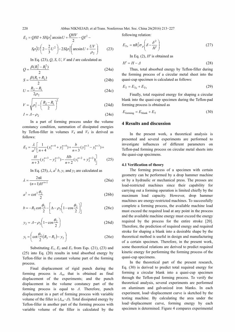
Two different groups of blanks with the same blank thickness of 0.6 mm and blank diameter of 50 mm and with the same Teflon characteristics but different material types of aluminum and galvanized iron are prepared and tested by the same rigid punch to study influences of blank material type on the forming process. Figure 8 shows theoretical curve of forming energy versus flow stress of blank material and the corresponding experimental results (solid square points) of specimens P05-AL060-R and P05-GA060-R. The specimens have the same geometrical dimensions of blank, punch and Teflon-filler and the same filler of polyurethane Teflon but different blank materials of aluminum and galvanized iron. According to Fig. 8, it is found that when flow stress of blank is enhanced, required energy for the forming process increases, based on both theoretical predictions and experimental results. Good correlation between the results affirms validity of derived theoretical Eq. (30). Figure 9 illustrates similar results of theoretical predictions and experimental results of the blanks P05-AL060-W and P05-GA060-W that are formed by PVC Teflon-filler. The specimens have
Abbas NIKNEJAD, et al/Trans. Nonferrous Met. Soc. China 26(2016) 213−227
223
different material types of aluminum and galvanized iron, but their other characteristics are the same. Theoretical and experimental values show the same incremental trend of forming energy with respect to flow stress of blank material, which is another proof of authenticity of the present theory.
Fig. 8 Theoretical curve and experimental results of forming energy versus flow stress of blank material during shaping process with polyurethane Teflon-filler on rigid punch P05
Fig. 9 Theoretical curve and experimental results of forming energy versus flow stress of blank material during shaping process with PVC Teflon-filler on rigid punch P05 4.4 Effects of angle γ
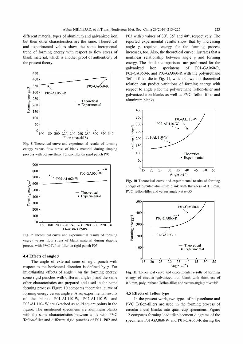
The angle of external cone of rigid punch with respect to the horizontal direction is defined by γ. For investigating effects of angle γ on the forming energy, some rigid punches with different angles γ and the same other characteristics are prepared and used in the same forming process. Figure 10 compares theoretical curve of forming energy versus angle γ. Also, experimental results of the blanks P01-AL110-W, P02-AL110-W and P03-AL110- W are sketched as solid square points in the figure. The mentioned specimens are aluminum blanks with the same characteristics between a die with PVC Teflon-filler and different rigid punches of P01, P02 and
P03 with γ values of 30°, 35° and 40°, respectively. The reported experimental results show that by increasing angle γ, required energy for the forming process increases, too. Also, the theoretical curve illustrates that a nonlinear relationship between angle γ and forming energy. The similar comparisons are performed for the galvanized iron specimens of P01-GA060-R, P02-GA060-R and P03-GA060-R with the polyurethane Teflon-filled die in Fig. 11, which shows that theoretical relation can predict variations of forming energy with respect to angle γ for the polyurethane Teflon-filler and galvanized iron blanks as well as PVC Teflon-filler and aluminum blanks.
Fig. 10 Theoretical curve and experimental results of forming energy of circular aluminum blank with thickness of 1.1 mm, PVC Teflon-filler and versus angle γ at α=55°
Fig. 11 Theoretical curve and experimental results of forming energy of circular galvanized iron blank with thickness of 0.6 mm, polyurethane Teflon-filler and versus angle γ at α=55°
4.5 Effects of Teflon type
In the present work, two types of polyurethane and PVC Teflon-fillers are used in the forming process of circular metal blanks into quasi-cup specimens. Figure 12 compares forming load−displacement diagrams of the specimens P01-GA060-W and P01-GA060-R during the
Abbas NIKNEJAD, et al/Trans. Nonferrous Met. Soc. China 26(2016) 213−227
224
shaping progress. Both the specimens are galvanized iron blanks with a thickness of 0.60 mm and a diameter of 50 mm and formed on the same rigid punch P01. Also, initial height of both types of used Teflon is selected to be 37 mm. Figure 12 shows that required load for the forming process of the blank with PVC Teflon-filled die is higher than that for the other, due to higher strength of PVC Teflon, compared with polyurethane Teflon-filler. Also, Fig. 12 shows that ultimate displacements of both the curves are close to each other, which means that, compressibilities of both Teflon-fillers of the studied tests during the forming process are approximately the same. Furthermore, forming energy−displacement of the blanks P01-GA060-W and P01-GA060-R are sketched in Fig. 13. Figure 13 shows that total required energies for shaping a galvanized iron blank with thickness of 0.60 mm during the Teflon-filled forming by PVC and polyurethane Teflon-fillers are equal to 335.8 and 174.7 J, respectively. This means that forming energy of the specimen with PVC Teflon-filler is 1.92 times that of the specimen with polyurethane Teflon-filler.
Fig. 12 Experimental forming load−displacement diagrams of specimens P01-GA060-W and P01-GA060-R during shaping progress
Fig. 13 Experimental forming energy−displacement diagrams of specimens P01-GA060-W and P01-GA060-R during shaping progress
4.6 Failure mechanisms of forming process During the performed shaping experiments on
circular metal blanks into quasi-cup specimens, two different undesirable phenomena are considered as failure mechanisms: rupture in zone I and wrinkling in zone III of formed blanks. Figure 14 illustrates an aluminum blank with initial diameter of 50 mm and thickness of 1.1 mm after the forming process, using PVC Teflon-filler. Figure 14 shows that rupture has occurred in central zone of the blank and it is due to radial expansion. On the other hand, when the depth of spherical part of rigid punches (or angle of α) increases, radial expansion that occurs in the central zone of the blank is enhanced, consequently, probability of rupture increases, too. This means that for each type of blanks with certain geometry and material characteristics, there is a limitation for angle α or depth of spherical part of the punch and when depth of central part of rigid punch is selected larger than the mentioned limit, rupture is considered in the blank during the forming process. Therefore, a rigid punch with deep central zone is prepared as shown in Fig. 15, and some blanks are compressed on it. The experiments show that when displacement of rigid punch reaches a certain value that is dependent on geometry and material type of blank, rupture initiates in the formed blank. So, in the
Fig. 14 Aluminum blank with initial diameter of 50 mm and thickness of 1.1 mm after forming process using PVC Teflon-filler
Fig. 15 Schematic sketch (a) and real picture (b) of rigid punch with deep central zone
Abbas NIKNEJAD, et al/Trans. Nonferrous Met. Soc. China 26(2016) 213−227
225
experimental part of the recent research, spherical geometry is used instead of conical geometry in the central zone of rigid punch and values of angle α are selected so that rupture does not occur in the specimen to achieve the desirable form of the samples.
Experimental observations show that at the edge of some formed quasi-cup specimens, wrinkling is considered as another failure mechanism of the forming process due to hoop contraction. Figure 16 illustrates two aluminum blanks P01-AL150-W and P07-AL150-W with diameter and thickness of 50 and 1.5 mm respectively after the forming process. The specimens are formed on rigid punches P01 and P07 with γ values of 30° and 60°, respectively. Figure 16 shows that wrinkling occurs at the edge of the specimen P07-AL150-W with γ=60°; while, no wrinkling is considered in specimen P01-AL150-W with γ=30°. This means that when external cone angle (γ) of rigid punches increases, probability of wrinkling phenomenon as a failure mechanism is enhanced, too. On the other hand, depending on blank geometry and material type, there is an upper limit for angle γ and forming process on rigid punches with angle γ less than that at which the mentioned limitation occurs without any wrinkling. Furthermore, experimental observations show that although forming energy of a certain blank with PVC Teflon-filler is higher than that of a similar specimen with polyurethane Teflon-filler, probability of wrinkling reduces when PVC Teflon-pad is used as the filler; and it is advantage of PVC Teflon-filler with respect to polyurethane Teflon-filler. This advantage is due to higher hardness of the used PVC Teflon-filler in the forming test, with respect to the used polyurethane Teflon-filler. When the Teflon hardness is higher, the distribution of pressure on the wrinkles is non-uniform and the pressure acting on the peak of the wrinkling is greater than that on the valley. Under this condition, the wave height verges to zero to eliminate the wrinkle with higher pressure [3].
Also, Figure 5 indicates that the errors of theoretical predictions for specimens P01-AL150-W and
Fig. 16 Two aluminum blanks P01-AL150-W and P07-AL150-W with diameter of 50 mm and thickness of 1.5 mm after forming process
P07-AL150-W are 36% and 47 %, respectively, with respect to the experimental results. The created wrinkling in the blank P07-AL150-W may be one of the reasons for higher error of theoretical forming energy, in comparison with the experiment. 4.7 Some applications of produced quasi-cup
specimens Energy absorbers are systems that convert kinetic
energy into other forms of energy, such as plastic deformation energy in deformable solids. The process of conversion in plastic deformation depends on magnitude and method of application of loads, transmission rates, deformation displacement patterns and material properties such as ductility and toughness [21]. There is a continuous need to develop crashworthy structures for transport applications. Various types of energy absorbers such as thin-walled tubes, columns and frustums, shells and metallic foams are usually designed for predominantly compressive loading and function by converting kinetic energy into irreversible plastic work [22]. There has been considerable activity on dynamic crush of thin-walled aluminum parts during the past decade. A significant part of this effort has been concerned with the use of these structures in energy absorbing systems. Increased interest on safety has led to a comprehensive research of the crash response of aluminum parts with different cross-sections and geometries by analytical, numerical and experimental methods [23]. Thin-walled structures with various geometries such as tubes [24], columns [25], honeycombs [26] and frustums [27] have been used as dissipated energy parts under different loadings. NIKNEJAD and TAVASSOLIMANESH [28] performed theoretical and experimental studies on plastic deformation mode and energy absorption by capped-end frusta during the inversion process under the axial loading in the quasi-static condition. They showed that capped-end cones of metal alloys are suitable energy absorber parts during crushing process. In the present work, shaping process of circular metal sheets into quasi-cup specimens was investigated to introduce the quasi-cup specimens as a new energy absorber part that can be studied in the next researches. 5 Conclusions
Shaping progress of circular metal blanks into quasi-cup specimens was investigated as a cold metal forming process by theoretical and experimental analyses. New theoretical deformation models were introduced for metal blank and Teflon-filler during the process, and based on them some theoretical relations were derived to predict total required energy for forming
Abbas NIKNEJAD, et al/Trans. Nonferrous Met. Soc. China 26(2016) 213−227
226
metal blanks into the quasi-cup samples. Comparisons showed that acceptable precision and accuracy of theoretical predictions with respect to the experimental results of forming energy of circular blanks with different material types of aluminum and galvanized iron, various blank thicknesses and punch dimensions, different Teflon-fillers of PVC and polyurethane. Also, theoretical estimations and experimental results illustrate incremental trend of forming energy with respect to blank thickness and flow stress of blank material. The reported experimental results show that by increasing angle γ, required energy for the forming process increases. Also, the theoretical curve illustrates a nonlinear relationship between angle γ and forming energy. In addition, experimental observations show that forming energy of a certain blank with PVC Teflon-filler is higher than that of a similar specimen with polyurethane Teflon-filler; but, probability of wrinkling decreases when PVC Teflon-pad is used as the filler. It is the advantage of PVC Teflon-filler with respect to polyurethane Teflon. References [1] THIRUVARUDCHELVAN S. The potential role of flexible tools in
metal forming [J]. Journal of Materials Processing Technology, 2002, 122: 293−300.
[2] RAMEZANI M, RIPIN Z M, AHMAD R. Computer aided modelling of friction in rubber-pad forming process [J]. Journal of Materials Processing Technology, 2009, 209: 4925−4934.
[3] SUN Yong-na, WAN Min, WU Xiang-dong. Wrinkling prediction in rubber forming of Ti-15-3 alloy [J]. Transactions of Nonferrous Metals Society of China, 2013, 23(10): 3002−3010.
[4] BROWNE D J, BATTIKHA E. Optimisation of aluminium sheet forming using a flexible die [J]. Journal of Materials Processing Technology, 1995, 55: 218−223.
[5] SUN Yong-na, WAN Min, WU Xiang-dong. Friction coefficient in rubber forming process of Ti-15-3 alloy [J]. Transactions of Nonferrous Metals Society of China, 2012, 22(12): 2952−2959.
[6] THIRUVARUDCHELVAN S. Elastomers in metal forming: A review [J]. Journal of Materials Processing Technology, 1993, 39: 55−82.
[7] AL-QURESHI H A. Analysis of simultaneous sheet metal forming operations using elastomer technique [J]. Journal of Materials Processing Technology, 2002, 125−126: 751−755.
[8] HIRUVARUDCHELVAN S. A urethane clamp as a metal-forming tool [J]. Journal of Materials Processing Technology, 1993, 38: 491−500.
[9] THIRUVARUDCHELVAN S. A theory for the bulging of aluminum tubes using a urethane rod [J]. Journal of Materials Processing Technology, 1994, 41: 311−330.
[10] DONG Guo-jiang, ZHAO Chang-cai, CAO Miao-yan. Flexible-die forming process with solid granule medium on sheet metal [J]. Transactions of Nonferrous Metals Society of China, 2013, 23(9): 2666−2677.
[11] WANG Zhong-jin, YUAN Bin-xian. Numerical analysis of coupled finite element with element-free Galerkin in sheet flexible-die forming [J]. Transactions of Nonferrous Metals Society of China, 2014, 24(2): 462−469.
[12] RAMEZANI M, RIPIN Z M, AHMAD R. Sheet metal forming with the aid of flexible punch, numerical approach and experimental validation [J]. CIRP Journal of Manufacturing Science and Technology, 2010, 3: 196−203.
[13] LIU Yan-xiong, HUA Lin, LAN Jian, WEI Xi. Studies of the deformation styles of the rubber-pad forming process used for manufacturing metallic bipolar plates [J]. Journal of Power Sources, 2010, 195: 8177−8184.
[14] CHEN Lei, CHEN Hui-qin, WANG Qiao-yi, LI Zhi-hua. Studies on wrinkling and control method in rubber forming using aluminum sheet shrink flanging process [J]. Materials and Design, 2015, 65: 505−510.
[15] WANG X Y, XIA J C, HU G A, WANG Z J, WANG Z R. Sheet bulging experiment with a viscous pressure-carrying medium [J]. Journal of Materials Processing Technology, 2004, 151: 340−344.
[16] LIU Jian-guang, WANG Zhong-jin. Prediction of wrinkling and fracturing in viscous pressure forming (VPF) by using the coupled deformation sectional finite element method [J]. Computational Materials Science, 2010, 48: 381−389.
[17] MOROVVATI M R, MOLLAEI DARIANI B, ASADIAN ARDAKANI M H. A theoretical, numerical, and experimental investigation of plastic wrinkling of circular two-layer sheet metal in the deep drawing [J]. Journal of Materials Processing Technology 2010, 210: 1738−47.
[18] NIKNEJAD A, REZAEE N, JAHANBAZI A F. Experimental investigation of Teflon-pad forming on circular metal blanks using a concave die [J]. Journal of Manufacturing Processes, 2015, 20: 282−290.
[19] SANTOSA S P, WIERZBICKI T, HANSSEN A G, LONGSETH M. Experimental and numerical studies of foam-filled sections [J]. International Journal of Impact Engineering, 2000, 24: 509−534.
[20] DIETER G E. Mechanical metallurgy [M]. Singapore: McGraw-Hill Book Co., 1988.
[21] ALGHAMDI A A A, ALJAWI A A N, ABU-MANSOUR T M N. Modes of axial collapse of unconstrained capped frusta [J]. International Journal of Mechanical Sciences, 2002, 44: 1145−1161.
[22] AKISANYA A R, FLECK N A. Plastic collapse of thin-walled frusta and egg-box material under shear and normal loading [J]. International Journal of Mechanical Sciences, 2006, 48: 799−808.
[23] GHAMARIAN A, ZAREI H R, ABDI M T. Experimental and numerical crashworthiness investigation of empty and foam-filled end-capped conical tubes [J]. Thin-Walled Structures, 2011, 49: 1312−1319.
[24] NIKNEJAD A, REZAEI B, LIAGHAT G H. Empty circular metal tubes in the splitting process: Theoretical and experimental studies [J]. Thin-Walled Structures, 2013, 72: 48−60.
[25] NIKNEJAD A, LIAGHAT G H, MOSLEMI NAEINI H, BEHRAVESH A H. Theoretical and experimental studies of the instantaneous folding force of the polyurethane foam-filled square honeycombs [J]. Materials and Design, 2011, 32: 69−75.
[26] ZHANG Z H, LIU S T, TANG Z L. Crashworthiness investigation of kagome honeycomb sandwich cylindrical column under axial crushing loads [J]. Thin-Walled Structures, 2010, 48: 9−18.
[27] ALJAWI A A N, ALGHAMDI A A A, ABU-MANSOUR T M N, AKYURT M. Inward inversion of capped-end frusta as impact energy absorbers [J]. Thin-Walled Structures, 2005, 43: 647−664.
[28] NIKNEJAD A, TAVASSOLIMANESH A. Axial compression of the empty capped-end frusta during the inversion progress [J]. Materials and Design, 2013, 49: 65−75.
Abbas NIKNEJAD, et al/Trans. Nonferrous Met. Soc. China 26(2016) 213−227
227
圆形金属坯加工成类杯形样品成形工艺的
理论和实验研究
Abbas NIKNEJAD, Iman KARAMI FATH
Mechanical Engineering Department, Yasouj University, P. O. Box 75914-353 Yasouj, Iran