Tehachapi Wind Energy Storage Project 2014 DOE/OE Energy Storage Systems Program Peer Review September 17-19 2014 Loïc Gaillac Advanced Energy Storage Group Manager Advanced Technology Southern California Edison
Transcript
Tehachapi Wind Energy Storage
Project 2014 DOE/OE Energy Storage Systems
Program Peer Review
September 17-19 2014
Loïc Gaillac
Advanced Energy Storage Group Manager
Advanced Technology
Southern California Edison
• 14 million customers: one of the
largest utilities in US
• 125 years of service
• Award-winning energy efficiency
and demand response programs
Southern California Edison
Committed to
safely providing,
reliable and affordable electric
service
2
3
SCE Advanced Technology Focus
• Implementing government policies and regulations and improving current utility operations
• Enabling customer adoption of new energy technologies
• Acquiring a deep understanding of the performance and controls of distributed resources
• Investing in next generation infrastructure to enable utilities to be the “optimizer” of distributed resources
Project Objectives
• Test Battery Energy Storage System as a system reliability and/or market driven device – Demonstrate the performance of a lithium-ion Battery
Energy Storage System (BESS) for 13 specific operational uses, both individually and bundled
– Share data and results with CAISO, CEC, CPUC, DOE, and other interested parties
– Assist in the integration of large-scale variable energy resources
• Integrate battery storage technology into SCE’s grid – Test and demonstrate smart inverter technology – Assess performance and life cycle of grid-connected
lithium-ion BESS – Expand expertise in energy storage technologies and
operations
4
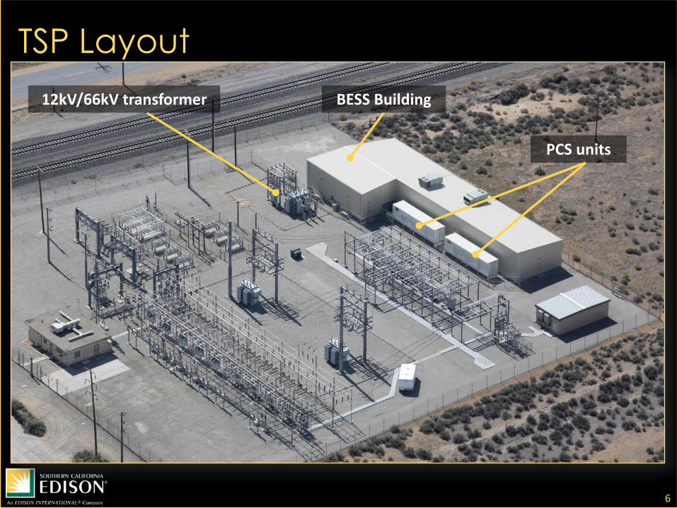
• Located in the Tehachapi area, California’s largest wind resource
• Massive wind development potential (up to 4,500MW) driving grid infrastructure
• Installed at SCE’s Monolith Substation
• 6,300 ft2 building
• Connected at sub-transmission level through a 12/66kV transformer
5
BESS facility at Monolith
Substation
BESS facility and 12kV/66kV transformer
Tehachapi Storage Project (TSP) Facility
TSP Layout
6
PCS units
12kV/66kV transformer BESS Building
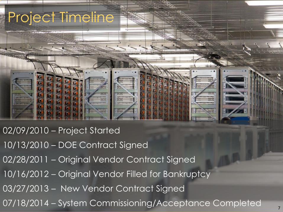
Project Timeline
02/09/2010 – Project Started
10/13/2010 – DOE Contract Signed
02/28/2011 – Original Vendor Contract Signed
10/16/2012 – Original Vendor Filled for Bankruptcy
03/27/2013 – New Vendor Contract Signed
07/18/2014 – System Commissioning/Acceptance Completed 7
System Specifications
• Battery Storage System – Li-Ion – Manufactured by LG
Chem. – 32MWh usable
• Power Conversion System – 9MVA – 12kV connected – Manufactured by
ABB
8
System Configuration
9
x 56 x 18 x 151 x 4
Cell Module Rack Section System
Quantity 609 k 10,872 604 4 1
Voltage 3.7 V 52 V 930 V 930 V 930 V
Energy 60 Wh 3.2 kWh 58 kWh 8.7 MWh 32 MWh
Weight 380 g 40 kg 950 kg N/A N/A
How to get 32MWh from 60Wh battery cells?
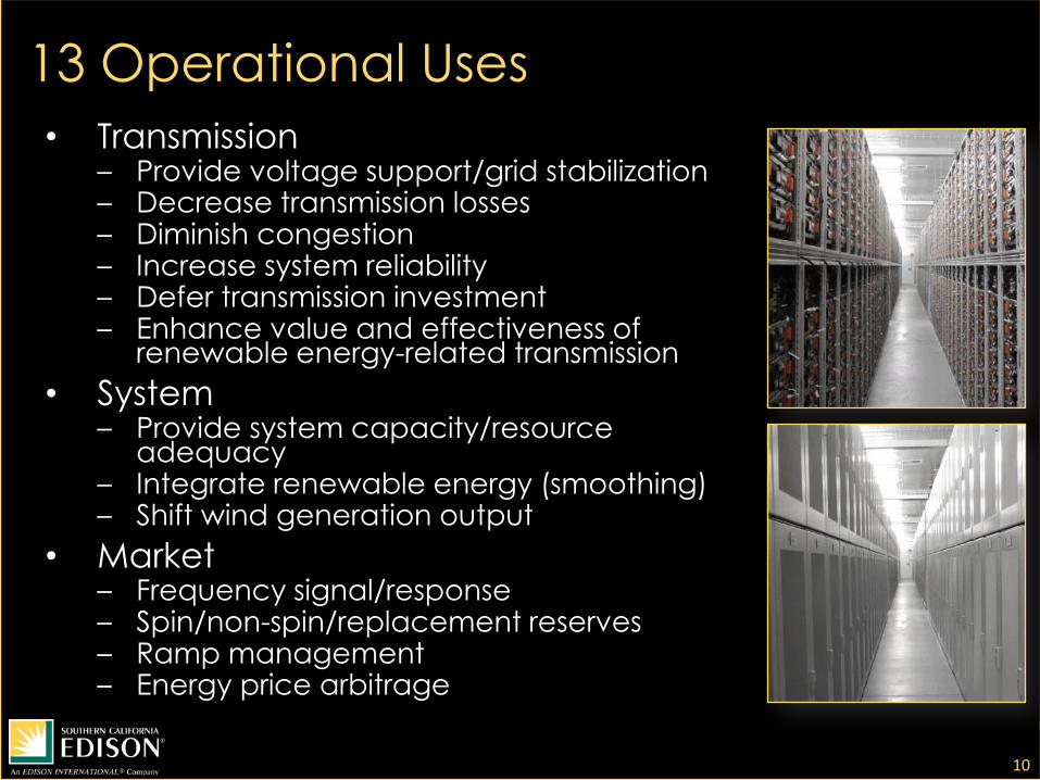
13 Operational Uses
• Transmission – Provide voltage support/grid stabilization – Decrease transmission losses – Diminish congestion – Increase system reliability – Defer transmission investment – Enhance value and effectiveness of
• Utilities need to assess safety and reliability prior to field deployment
• Issues with testing large systems in the field – Grid/personnel safety – Geographic distance – Need to exchange significant power at will – Hardware/firmware/software problems can take many
months to solve
14
System Validation Approach: Mini-System Lab Testing
Mini-System Full System
Footprint 77 ft2 6300 ft2
building
Power 30 kW 8 MW
Energy 116 kWh 32 MWh
Power
Conversion
System
One Mini-
Cabinet
Two 40-foot
containers
Sections 1 4
Banks 1 32
Racks 2 604
Modules 36 10,872
Cells 2,016 608,832
Mini-System for Subscale Testing
Mini-System enables subscale testing in the lab before full-scale operation of the BESS at Monolith Substation
15
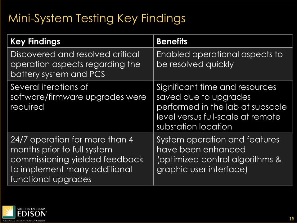
Mini-System Testing Key Findings
16
Key Findings Benefits
Discovered and resolved critical
operation aspects regarding the battery system and PCS
Enabled operational aspects to
be resolved quickly
Several iterations of
software/firmware upgrades were
required
Significant time and resources
saved due to upgrades
performed in the lab at subscale
level versus full-scale at remote
substation location
24/7 operation for more than 4 months prior to full system
commissioning yielded feedback
to implement many additional
functional upgrades
System operation and features have been enhanced
(optimized control algorithms &
graphic user interface)
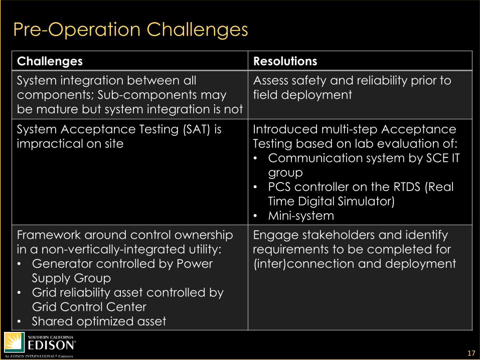
Pre-Operation Challenges
17
Challenges Resolutions
System integration between all
components; Sub-components may
be mature but system integration is not
Assess safety and reliability prior to
field deployment
System Acceptance Testing (SAT) is
impractical on site
Introduced multi-step Acceptance
Testing based on lab evaluation of:
• Communication system by SCE IT
group
• PCS controller on the RTDS (Real
Time Digital Simulator)
• Mini-system
Framework around control ownership
in a non-vertically-integrated utility:
• Generator controlled by Power
Supply Group
• Grid reliability asset controlled by
Grid Control Center
• Shared optimized asset
Engage stakeholders and identify
requirements to be completed for
(inter)connection and deployment
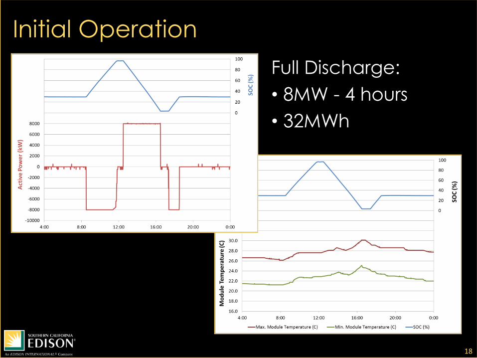
Initial Operation
18
Full Discharge:
• 8MW - 4 hours
• 32MWh
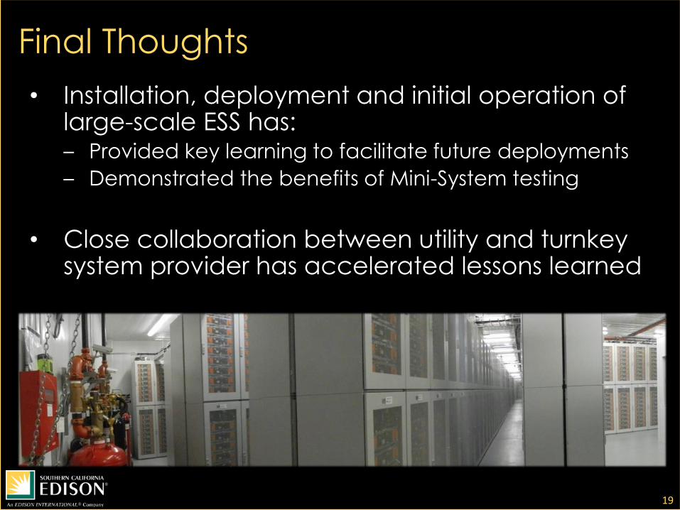
Final Thoughts
• Installation, deployment and initial operation of large-scale ESS has: – Provided key learning to facilitate future deployments
– Demonstrated the benefits of Mini-System testing
• Close collaboration between utility and turnkey system provider has accelerated lessons learned