28
| Date post: | 08-Feb-2018 |
| Category: |
Documents |
| Upload: | truongtuong |
| View: | 225 times |
| Download: | 1 times |
Thank you for purchasing our TEKKEN 3 (hereinafter mentioned as the game machine).
This manual shows you how to operate, install, transport, remove, maintain and discard this game machine insafety.
Be sure to read this manual and the instruction manual for cabinet to be used before installing and operating thisgame machine to ensure the safety and to operate correctly.
This manual applies to a staff of a game center. However, an article indicated as “It must be handled by anengineer.” applies to engineers, so the operation must be done by engineers only. Never someone else besides theengineer should operate it.
Engineer means the following personnel:
Personnel who had taken credits of mechanical or electrical engineering in university, college or high-school, or who have knowledge as same as one who had taken the above credits and also who maintains,takes care and repairs amusement machines as a daily work.
When an owner of this game machine leaves operation, installation, transportation, removal, maintenance anddiscard to the other person, instruct him/her to read the articles in point and to follow the regulations.
Keep this manual with care so as to read in case of need in daily operation.
In case of resell of the game machine, be sure to attach this manual to the PC board.
For inquiries about the game machine and servicing:
As for inquiries about the game machine and servicing for the machine, contact your distributor.

IntroductionTable of Contents1. Precautions on safety (for Safety Operation) 1
1-1 Explanation for a for calling attention: ........................................................... 1
1-2 Explanation for signal words WARNING. CAUTION) 11-3
21-4
31-5 Precautions on Safety with regard to Discard 3
2. Packing Substance Check 43. Specifications 5
3-1 Control Panel 5 3-2 Monitor 53-3 PC Board 6
4. Installation 74-1 Connection to a Cabinet corresponding to JAM A standard '7
4-1-I Connection of Control Panel 74-1-2 Connection of ard 84-1-3 Connection of r 8
4-2 Connection to a Cabinet corresponding to JA MA VIDEO standard (JVS) 94-2-1 Connection of Control Panel 94-2-2 Connection of PC Board 9
5. Adjustment 12Switch 12de 13
Precaution on Safety for operators in charge of Installation(It should be handled by an engineer.)Precaution on Safety for Operator in charge of Maintenance(It should be handled by an engineer.)
5-2-1 DISPLAY TEST 145-2-2 SWITCH TEST 185-2-3 SOUND TEST 185-2-4 JVS CABINET OPTIONS 135-2-5 GAME OPTIONS 205-2-6 COIN OPTIONS 225-2-7 A.D.S. 235-2-8 DATA CLEAR 245-2-9 EXIT & SAVE (Exit of TEST mode) 24
6. 257 . Transportation 258. PC Board Edge Connector List 26
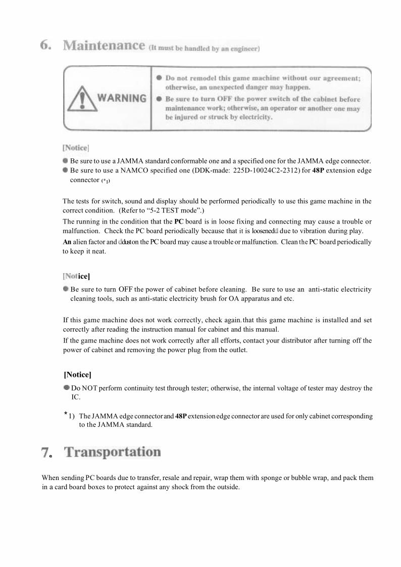
Maintenance (It must be handled by an engineer)
Do NOT remodel this game machine without our agreement;otherwise. an unexpected danger may happen.
The contents on this operation manual are subject to change without notice for improvement .
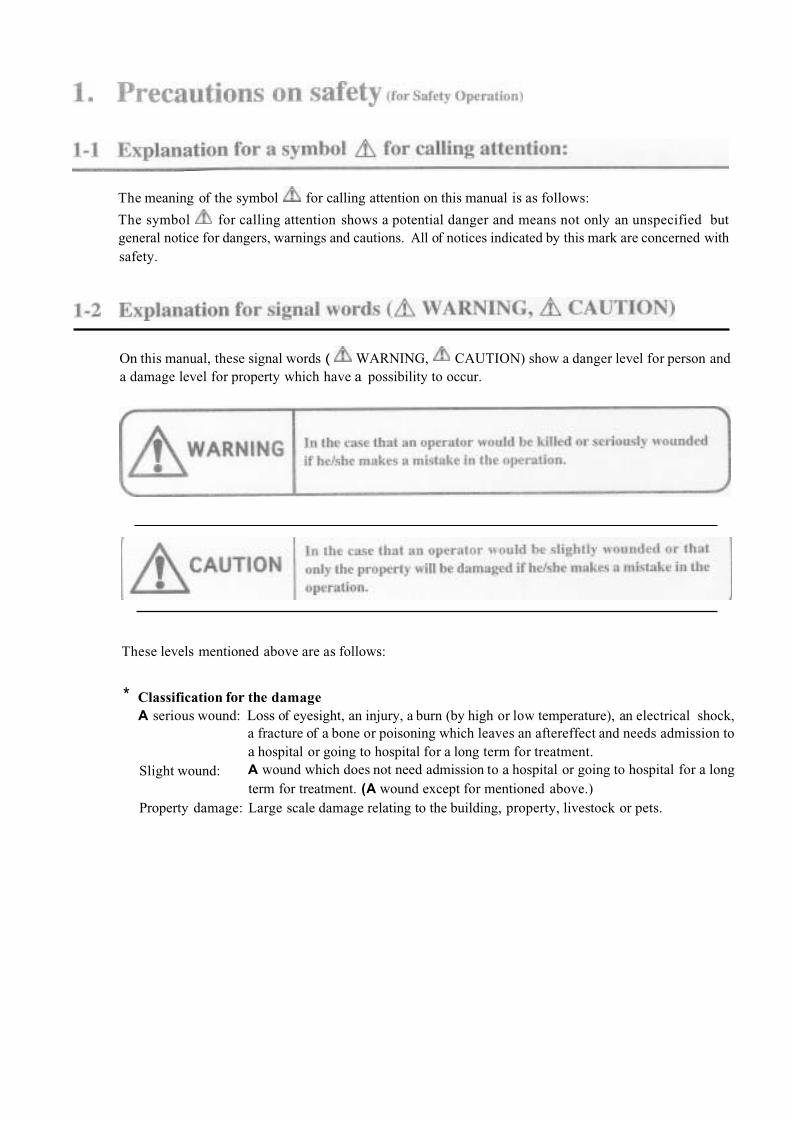
The meaning of the symbol for calling attention on this manual is as follows:
The symbol for calling attention shows a potential danger and means not only an unspecified butgeneral notice for dangers, warnings and cautions. All of notices indicated by this mark are concerned withsafety.
On this manual, these signal words ( WARNING, CAUTION) show a danger level for person and a damage level for property which have a possibility to occur.
These levels mentioned above are as follows:
* Classification for the damageA serious wound: Loss of eyesight, an injury, a burn (by high or low temperature), an electrical shock,
a fracture of a bone or poisoning which leaves an aftereffect and needs admission toa hospital or going to hospital for a long term for treatment.A wound which does not need admission to a hospital or going to hospital for a longterm for treatment. (A wound except for mentioned above.)
Slight wound:
Property damage: Large scale damage relating to the building, property, livestock or pets.
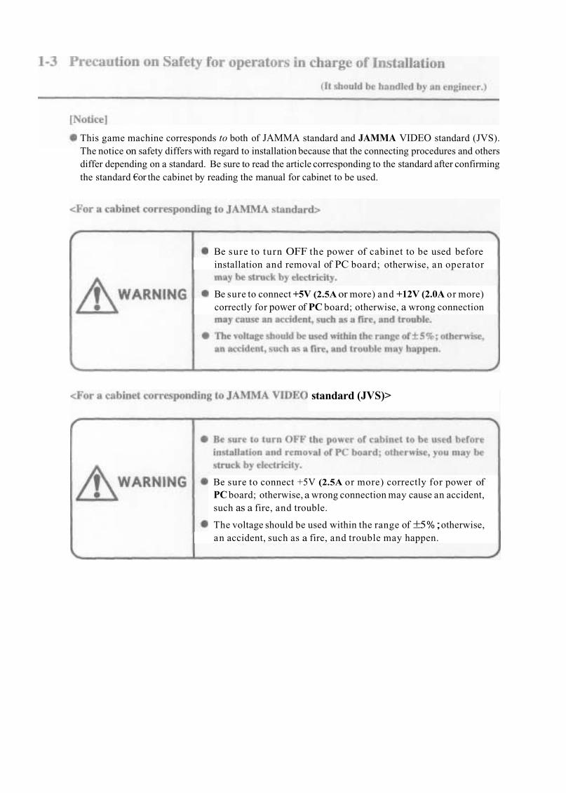
This game machine corresponds to both of JAMMA standard and JAMMA VIDEO standard (JVS).The notice on safety differs with regard to installation because that the connecting procedures and othersdiffer depending on a standard. Be sure to read the article corresponding to the standard after confirmingthe standard €or the cabinet by reading the manual for cabinet to be used.
Be sure to turn OFF the power of cabinet to be used beforeinstallation and removal of PC board; otherwise, an operator
Be sure to connect +5V (2.5A or more) and +12V (2.0A or more)correctly for power of PC board; otherwise, a wrong connection
standard (JVS)>
Be sure to connect +5V (2.5A or more) correctly for power ofPC board; otherwise, a wrong connection may cause an accident,such as a fire, and trouble.
The voltage should be used within the range of±5%;otherwise,an accident, such as a fire, and trouble may happen.

Do NOT remodel this game machine without our agreement;otherwise, an unexpected danger may happen.
Be sure to torn OFF the power switch of the cabinet beforeerwise, an operator or anot
i scarded, performorks in the proce
If an owner o f this ga achine leaves gs for discard to

This game machine consists of the followings.
[Notice]
Make sure that the following substances are complete.
*1) On the adhesive side of A sticker, B sticker and button seal, a “release type’’bonding agent, which ishard to leave a mark after peeling it off, is used.
*2) This game machine corresponds to both of JAMMA standard and JAMMA VIDEO standard (JVS). The kick harness is not necessary if the PC board is connected to a cabinet corresponding to JAMMA VIDEO standard (JVS). (Refer to “3-3 PC Board” for connection terminal of each standard.)

2-P specifications
8-direction lever : 1 x 2Button switch : 4 x 2Start switch : 1 x 2
P1-START switch P2-START switch
P2 8-direction P2 Burton I
irection of monitor: Horizontal
Scanning retrace line for Interlace/non-interlace: selectable
Synchronizing signal: Composite/separate: selectable (*1)
Horizontal synchronizingfrequency: 15.75 kHz
Vertical synchronizing frequency: 60.0 Hz
*1) Only for connection of cabinet corresponding to JAMMA VIDEO standard (JVS)

The PC board corresponds to both of JAMMA standard and JAMMA VIDEO standard (JVS)
Audio output Connector 2Audio output connector 1
Video output connector 2
Video output connector 1
DC power connector
Size :
Power supply (when connecting JAMMA standar
260 x 230 (mm) (excluding part projected)
+5V±5% (2.5A or more), +12V ±5% (2.0A or more)
ly (when connecting
+5V ± 5 % (2.5A or more)
48P extension edge connector / 56P edge connector (JAMMA)
*1) Used to connect to a cabinet corresponding to JAMMA standard.
*2)Used to connect to a cabinet corresponding to JAMMA VIDEO standard (JVS).
[Notice]
This game machine corresponds to both of JAMMA standard and JAMMA VIDEO standard (JVS). Besure to read the article corresponding to the standard after confirming the standard for the cabinet by
manual for cabinet to be used.mark is indicated on the article for cabinet corresponding to JAMMA standard, and the
mark is indicated on the article for cabinet corresponding to JAMMA VIDEO standard (JVS).
o S
[Notice]
Use +12V or less for line voltage of coin counter.
nnection of Control
Connect the JAMMA edge connector and kick harness (wired 48P extension edge connector) packedtogether to each appropriate switch of control panel with reference to “8.PC Board Edge Connector List”.
Be sure to use a JAMMA standard conformableone and a specified one for the JAMMA edge connector.Be sure to use a NAMCO specified one (DDK-made: 225D-10024C2-3312) for the 48P extension edgeconnector.Do not connect anything to the blank column on “8.PC Board Edge Connector List”Connect each switch and lever input of edge connector to N. 0.terminal, such as micro switch and etc.
e sure to connect the COM terminal to GND of edge connector for the micro switch wired.
After being sure to read the manual for cabinet to be used, connect the suitable control panel for this gamemachine (Refer to “3-1 Control Panel”.) to the cabinet.
e sure to turn OFF the power of cabinet to be used beforeinstaIlation and removal of PC board; otherwise, you may bestruck by electricity.
ect +5V (2.5A or more) correctlywise, a wrong connectionmay caus
After being sure to read the manual for cabinet to be used, connect the PC board according to the followingeplacement of game PC board on the instruction manual for “CYBERLEAD”
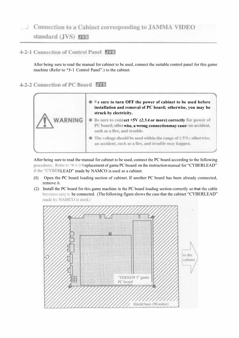
(1 ) Open the PC board loading section of cabinet. If another PC board has been already connected, remove it.
(2) Install the PC board for this game machine in the PC board loading section correctly so that the cablebe connected. (The following figure shows the case that the cabinet “CYBERLEAD”
LEAD” made by NAMCO is used as a cabinet.
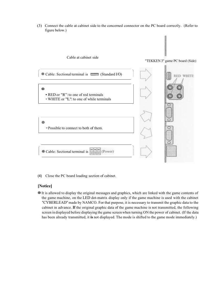
(3) Connect the cable at cabinet side to the concerned connector on the PC board correctly. (Refer tofigure below.)
RED or "R”:to one of red terminalsWHITE or "L": to one of while terminals
Cable at cabinet side
Possible to connect to both of them.
"TEKKEN 3" game PC board (Side)
Cable: Sectional terminal is (Standard I/O)
Cable: Sectional terminal is
(4) Close the PC board loading section of cabinet.
[Notice]
It is allowed to display the original messages and graphics, which are linked with the game contents ofthe game machine, on the LED dot-matrix display only if the game machine is used with the cabinet"CYBERLEAD" made by NAMCO. For that purpose, it is necessary to transmit the graphic data to thecabinet in advance. If the original graphic data of the game machine is not transmitted, the followingscreen is displayed before displaying the game screen when turning ON the power of cabinet. (If the datahas been already transmitted, it is not displayed. The mode is shifted to the game mode immediately.)
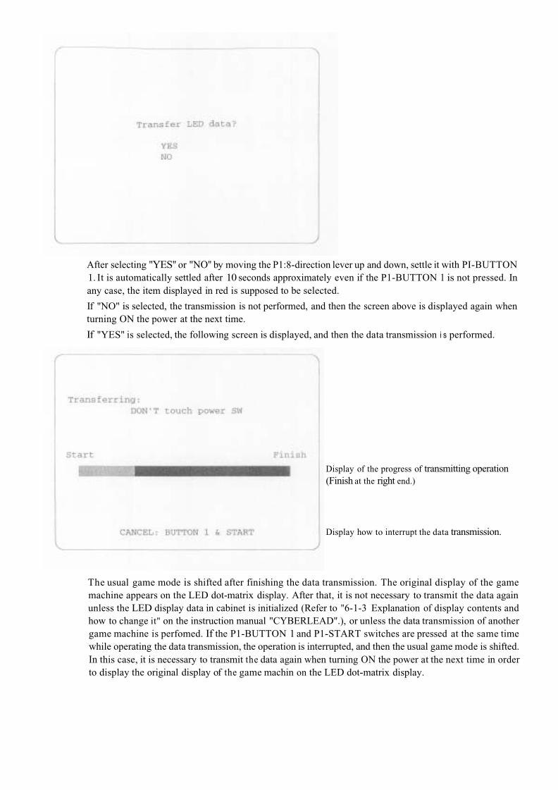
After selecting "YES" or "NO" by moving the P1:8-direction lever up and down, settle it with PI-BUTTON1. It is automatically settled after 10 seconds approximately even if the P1-BUTTON 1 is not pressed. Inany case, the item displayed in red is supposed to be selected.
If "NO" is selected, the transmission is not performed, and then the screen above is displayed again when turning ON the power at the next time.
If "YES" is selected, the following screen is displayed, and then the data transmission i s performed.
Display of the progress of transmitting operation (Finish at the right end.)
Display how to interrupt the data transmission.
The usual game mode is shifted after finishing the data transmission. The original display of the game machine appears on the LED dot-matrix display. After that, it is not necessary to transmit the data againunless the LED display data in cabinet is initialized (Refer to "6-1-3 Explanation of display contents and how to change it" on the instruction manual "CYBERLEAD".), or unless the data transmission of anothergame machine is perfomed. If the P1-BUTTON 1 and P1-START switches are pressed at the same timewhile operating the data transmission, the operation is interrupted, and then the usual game mode is shifted. In this case, it is necessary to transmit the data again when turning ON the power at the next time in orderto display the original display of the game machin on the LED dot-matrix display.

.
The adjusting switch on the PC board is as follows:
(1) Optional switch This switch is a pair of two units.If the #1 is “ON”, the mode is in TEST mode.If the #2 is “ON”, the screen is in STOP.All of switches is usually “OFF”.
[Notice]
The nomal game is not allowed to be performed if the optional switch #2 is in “ON”state.
(2) Speaker volumeTurning it clockwise, the volume of speaker becomes large. Turning it counterclockwise, the volume of speaker becomes small.
[Notice]
The speaker volume can not work for volume adjustment, if the cabinet corresponding to JAMMAVIDEO standard (JVS) is used. After being sure to read the manual for cabinet to be used, performvolume setting at cabinet side.

the test menu screen is displayed.
Use the test switch on the cabinet (Refer to “8. PC Board Edge Connector List” to perform connection.) orthe optional switch on the PC board. (Refer to “5-1 Adjusting switch”.)
After selecting an item (displayed in red) on the test screen by moving the P1:8-direction lever up anddown, press the PI-BUTTON 1 to display the selected test screen.
[Notice]
The “JVS CABINET OPTIONS” is not allowed to be selected if the PC board is connected from theJAMMA edge connector. It is allowed to be selected only if the PC board is connected from theconnector corresponding to JAMMA VIDEO standard (JVS).
When exiting the TEST mode ,be sure to select “EXIT & SAVE” from the test menu screen as belowbefore pressing P1-BUTTON 1 to end it.
TEST (5-2-1)DISPLAYWITCH TEST (5-2-2)OUND TEST
VS CABINET OPTIONS (5-2-4)GAME OPTIONS (5-2-5)COIN OPTIONS (5-2-6)A.D.S.DATA CLEAREXIT & SAVE (Exit of TEST mode)
(5-2-9)
[Notice]
If the procedure above is not used for exiting of TEST mode, a changed setting may not be reflectedcorrectly. Be sure to select “EXIT & SAVE” from the test menu screen before pressing P1-BUTTON 1to end it.
In both cases that the test switch on the cabinet is the slide type and that the optional switch #1 on the PCboard is used, take note of the followings.
The mode enters the TEST mode when switching the test switch on the cabinet or the optional switch#1 on the PC board to ON from OFF. If the switch has been turned ON before the mode enters TESTmode, turn it ON again after turning it OFF once.The test mode is not exited even if the test swi ed OFF. Be sure to select “EXIT & SAVE”
from the test menu screen before pressing P1- 1 to end it.

This mode performs test and setting on the screen display.
The DISPLAY TEST provides 1 kind of common display and 3 kinds of test pattern.
(1) COLOR EDITThis screen performs balance adjustment for brightness and color tone of display signal output from the PC board.
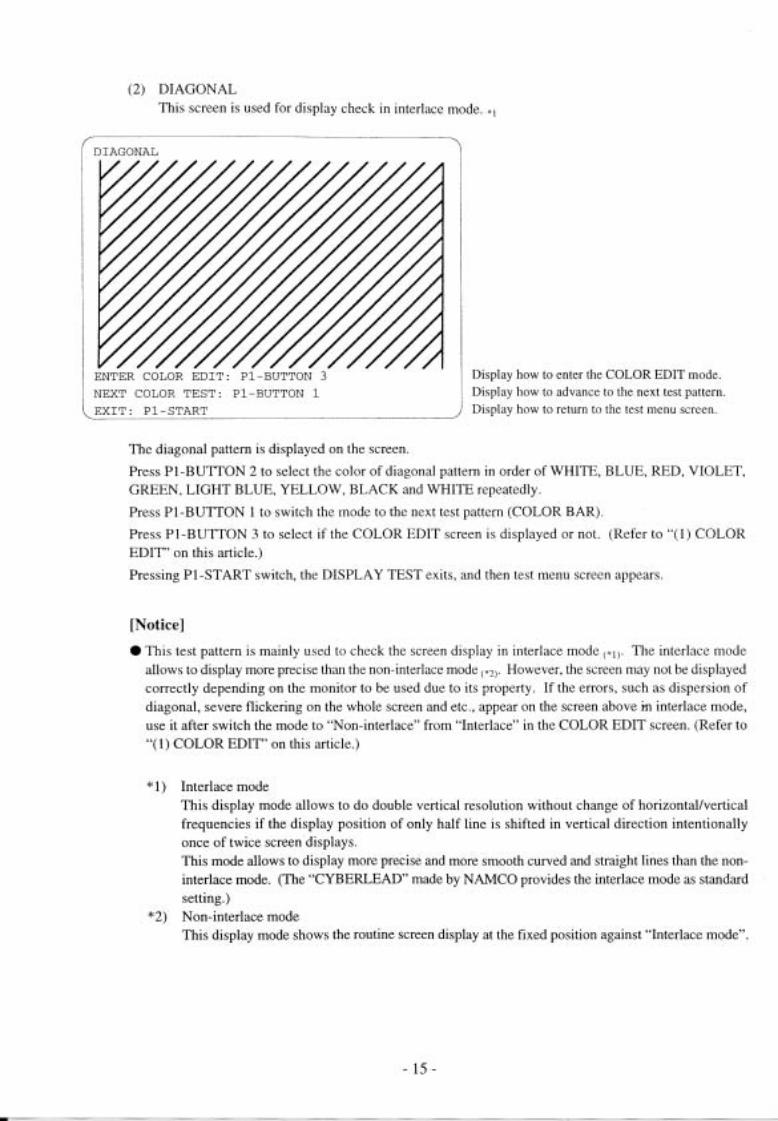
This screen is used for display check in interlace mode.
This screen is used for balance check and adjustment for brightness and color tone.
This screen is used for check and adjustment for display size, display position, ratio length tobreadth and distortion.
The screen (1), which is the common display, is displayed so as to overlap on the screens (2) to (4). PressP1-BUTTON 3 to select if screen (1) is displayed or not.
The screens (2) to (4)are the test display, The screen (2) is displayed immediately after entering DISPLAYTEST mode. Press PI-BUTTON 1 to select the screen in order of (2) ,(3), (4)and (2) repeatedly. Pressing P1-START switch, the DISPLAY TEST mode exits and then the test menu screen appears.
(2) DIAGONAL
(3) COLOR BAR
(4) CONVERGENCE
Scanning retrace line format on monitor
Whole contrast
Brightness (RED)Brightness (GREEN)
Brightness (BLUE)
( I ) COLOR EDIT This screen performs balance adjustment for brightness and color tone of display signal output fromthe PC board.
Non InterlaceContrast:Bright R:Bright G:
Bright B:
PREVIOUS VALUE: PI-BUTTON 4
EXIT COLOR EDIT: P1-BUTTON 3
NEXT COLOR TEST: P1-BUTTON1EXIT: P1-START
Display how to return a value to the initial value.
Display how to exit the COLOR EDIT mode.Display how to advance to the next test pattern.
Display how to return to the test menu screen.
The above screen appears while overlapping on the test pattern.
After selecting an item to be changed by moving the P1:8-direction lever up and down, move it right and left to change the setting.
Pressing P1-BUTTON 4, all of contents changed on the COLOR EDIT screen are canceled.
Pressing P1-BUTTON 3 , the COLOR EDIT screen is suspended, and then the display of setting items disappear.
Pressing P1-BUTTON 3 once again, the setting items are displayed again, and then the COLOR edit screen becomes available.
Pressing PI-START switch, whole DISPLAY TEST exits, and then the test menu screen appears.
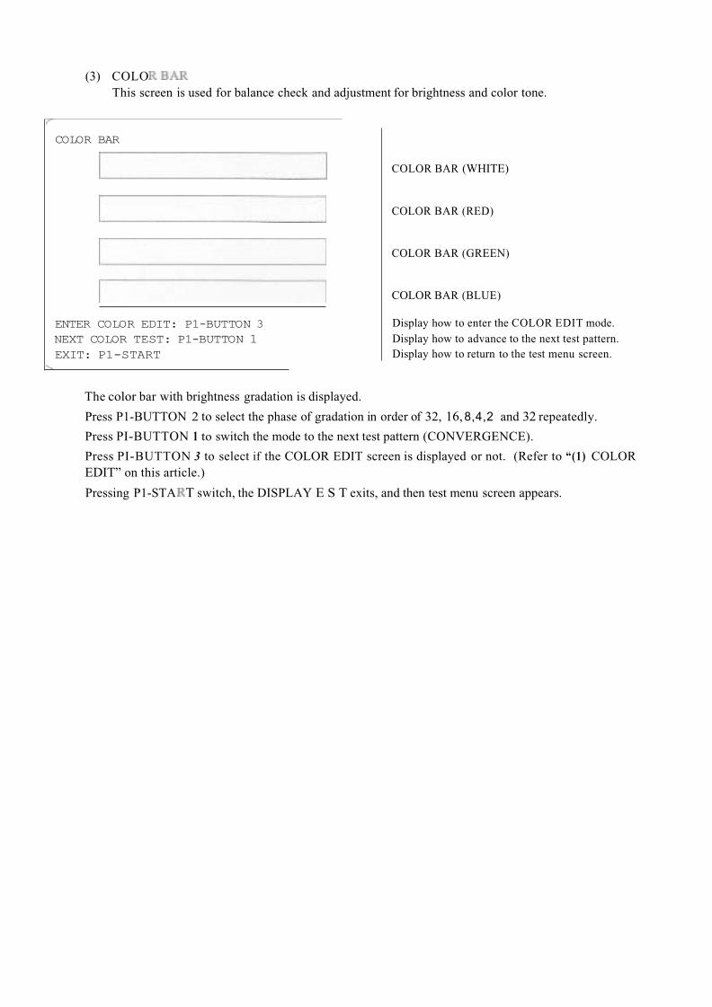
(3) COLOThis screen is used for balance check and adjustment for brightness and color tone.
COLOR BAR
ENTER COLOR EDIT: P1-BUTTON 3NEXT COLOR TEST: P1-BUTTON 1EXIT: P1-START
COLOR BAR (WHITE)
COLOR BAR (RED)
COLOR BAR (GREEN)
COLOR BAR (BLUE)
Display how to enter the COLOR EDIT mode.Display how to advance to the next test pattern.Display how to return to the test menu screen.
The color bar with brightness gradation is displayed.
Press P1-BUTTON 2 to select the phase of gradation in order of 32, 16,8,4,2 and 32 repeatedly.
Press PI-BUTTON 1 to switch the mode to the next test pattern (CONVERGENCE).
Press PI-BUTTON 3 to select if the COLOR EDIT screen is displayed or not. (Refer to “(1) COLOREDIT” on this article.)
Pressing P1-STA T switch, the DISPLAY E S T exits, and then test menu screen appears.

(4) CONVERGENCEThis screen is used for check and adjustment for display size, display position, ratio length to breadthand distortion.
CONVERGENCE
CROSS HATCH PATTERN
Display how to enter the COLOR EDIT mode.NEXT COLOR TEST: P1-BUTTON 1 Display how to advance to the next test pattern. E X I T : Display how to return to the test menu screen.P1-START
The cross pattern called as “Cross hatch pattern” is displayed on the screen.
Press PI-BUTTON 2 to select the color of cross hatch pattern in order of WHITE, BLUE, RED, VIOLET,GREEN, LIGHT BLUE, YELLOW, BLACK and WHITE repeatedly.
Press P1-BUTTON I to switch the mode to the next test pattern (DIAGONAL).
Press P1-BUTTON 3 to select if the COLOR EDIT screen is displayed or not. (Refer to “(1) COLOR EDIT” on this article.)
Pressing P1-START switch, the DISPLAY TEST exits, and then test menu screen appears.
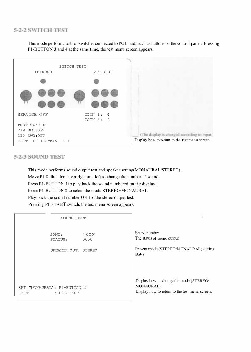
This mode performs test for switches connected to PC board, such as buttons on the control panel. Pressing P1-BUTTON 3 and 4 at the same time, the test menu screen appears.
SWITCH TEST1P:0000 2P:0000
SERVICE:OFF COIN 1: 0COIN 2: 0
TEST SW:OFFDIP SW1:OFFDIP SW2:OFFEXIT: P1-BUTTON3 & 4 Display how to return to the test menu screen.
This mode performs sound output test and speaker setting(MONAURAL/STEREO).
Move P1:8-direction lever right and left to change the number of sound.
Press P1-BUTTON 1 to play back the sound numbered on the display.
Press P1-BUTTON 2 to select the mode STEREO/MONAURAL.
Play back the sound number 001 for the stereo output test.
Pressing P1-STA T switch, the test menu screen appears.
SOUND TEST
SONG: [000]STATUS: 0000
SPEAKER OUT: STEREO
SET "MONAURAL": P1-BUTTON 2EXIT : P1-START
Sound number The status of sound output
Present mode (STEREO/MONAURAL) settingstatus
Display how to change the mode (STEREO/MONAURAL).Display how to return to the test menu screen.

This mode performs setting for cabinet corresponding to JAMMA VIDEO standard (JVS).
J V S CABINET OPTIONS<DEFAULTS IN GREEN,
VIDEO SYNC: Composite
JAMMA VIDEO STANDARD [STEP 1]
Main
I/O 1
I/O 2
EXIT:P1-START
Display with regard to theJAMMA VIDEO standard
(JVS)
[Notice]
This article is not available if the cabinet is connected from the JAMMA edge connector on the PCboard.
Press P1-BUTTON 1to change the setting.
Pressing P1-START switch, the setting screen exits, and then test menu screen appears.
(a) VIDEO SYNC (Synchronizing signal output format of video output)
C o m p o s l t e (Composite synchronization) Separate (Vertlca/horizontal synchronization)
Thick frame: initial value
[Notice]
If the VIDEO SYNC is set at "Separate", the picture becomes more clear than "Composite".As for use of cabinet "CYBERLEAD" made by NAMCO, set the VIDEO SYNC at "Composite" if anapparatus is connected to the line output display terminal at rear side. (Refer to "4-4 Explanation ofexternal I/O terminal" on the instruction manual "CYBERLEAD".)
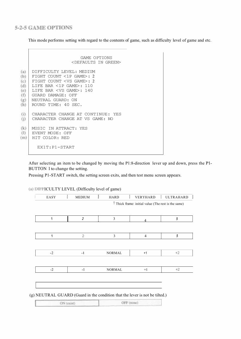
This mode performs setting with regard to the contents of game, such as difficulty level of game and etc.
I I 41 2 3
GAME OPTIONS <DEFAULTS IN GREEN>
5
DIFFICULTY LEVEL: MEDIUMFIGHT COUNT <1P GAME>: 2FIGHT COUNT <VS GAME>: 2LIFE BAR <1P GAME>: 110LIFE BAR <VS GAME>: 140GUARD DAMAGE: OFFNEUTRAL GUARD: ONROUND TIME: 40 SEC.
1 2 3 4
CHARACTER CHANGE AT CONTINUE: YESCHARACTER CHANGE AT VS GAME: NO
5
MUSIC IN ATTRACT: YES EVENT MODE: OFFHIT COLOR: RED
-2 - 1 NORMAL +1
EX1T:P1-START
+2
After selecting an item to be changed by moving the P1:8-direction lever up and down, press the P1-BUTTON 1to change the setting.
Pressing P1-START switch, the setting screen exits, and then test menu screen appears.
-2 -1 NORMAL +1
ICULTY LEVEL (DifficuIty level of game)
+2
EASY MEDIUM HARD VERYHARD ULTRAHARD
Thick frame: initial value (The rest is the same)
(g) NEUTRAL GUARD (Guard in the condition that the lever is not be tilted.)
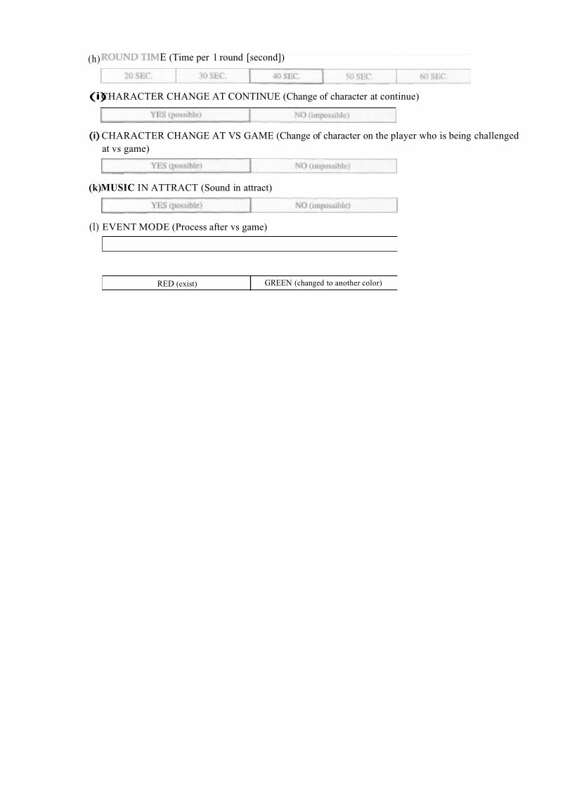
(h) E (Time per 1 round [second])
RED (exist)
(i)CHARACTER CHANGE AT CONTINUE (Change of character at continue)
GREEN (changed to another color)
(i)CHARACTER CHANGE AT VS GAME (Change of character on the player who is being challengedat vs game)
(k) MUSIC IN ATTRACT (Sound in attract)
(1) EVENT MODE (Process after vs game)
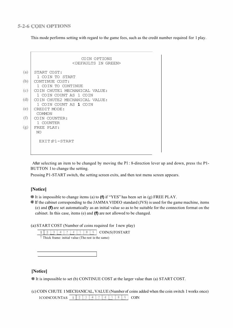
This mode performs setting with regard to the game fees, such as the credit number required for 1 play.
COIN OPTIONS<DEFAULTS IN GREEN>
START COST:1 COIN TO START
CONTINUE COST:1 COIN TO CONTINUECOIN CHUTE1 MECHANICAL VALUE: 1 COIN COUNT AS 1 COINCOIN CHUTE2 MECHANICAL VALUE: 1 COIN COUNT AS 1 COIN
CREDIT MODE: COMMONCOIN COUNTER:1 COUNTER
FREE PLAY:NO
EXIT: P1-START
After selecting an item to be changed by moving the P1 : 8-direction lever up and down, press the P1-BUTTON 1 to change the setting.
Pressing P1-START switch, the setting screen exits, and then test menu screen appears.
[Notice]
It is impossible to change items (a) to (f) if “YES” has been set in (g) FREE PLAY.If the cabinet corresponding to the JAMMA VIDEO standard (JVS) is used for the game machine, items(e) and (f) are set automatically as an initial value so as to be suitable for the connection format on thecabinet. In this case, items (e) and (f) are not allowed to be changed.
(a) START COST (Number of coins required for 1new play)
1 COIN(S) TO START Thick frame: initial value (The rest is the same)
[Notice]
It is impossible to set (b) CONTINUE COST at the larger value than (a) START COST.
(c) COIN CHUTE 1MECHANICAL, VALUE (Number of coins added when the coin switch 1 works once)
1COINCOUNTAS 1 COIN
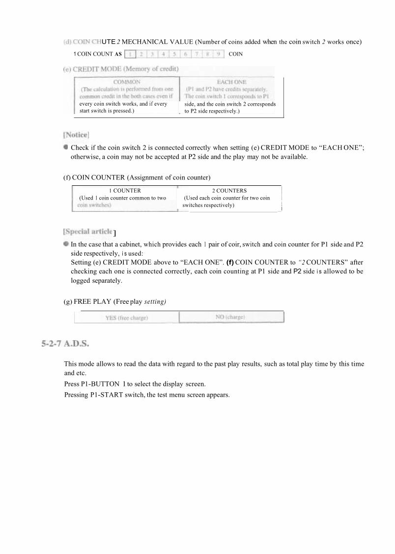
UTE 2 MECHANICAL VALUE (Number of coins added when the coin switch 2 works once)
1 COIN COUNT AS COIN
every coin switch works, and if everystart switch is pressed.)
side, and the coin switch 2 correspondsto P2 side respectively.)
Check if the coin switch 2 is connected correctly when setting (e) CREDIT MODE to “EACH ONE”;otherwise, a coin may not be accepted at P2 side and the play may not be available.
(f) COIN COUNTER (Assignment of coin counter)
1 COUNTER 2 COUNTERS(Used 1 coin counter common to two (Used each coin counter for two coin
switches respectively) i
]
In the case that a cabinet, which provides each 1 pair of coir, switch and coin counter for P1 side and P2side respectively, i s used:Setting (e) CREDIT MODE above to “EACH ONE”. (f) COIN COUNTER to “2 COUNTERS” afterchecking each one is connected correctly, each coin counting at P1 side and P2 side i s allowed to belogged separately.
(g) FREE PLAY (Free play setting)
This mode allows to read the data with regard to the past play results, such as total play time by this timeand etc.
Press P1-BUTTON 1 to select the display screen.
Pressing P1-START switch, the test menu screen appears.

This mode performs clear for the data which is stored even if the power is turned OFF.
BACKUP DATA CLEAR
CANCELADS DATA CLEARRANKING CLEARSET DEFAULTS ALL OPTIONSALL CLEAR
Return to the test menu screen.Clear A.D.S data only.Initialization of ranking data.Initialization of all options.
Clear all of data logged.
EXIT: P1-START Display how to return to the test menuscreen.
After selecting an item by moving the P1:8-direction lever up and down, press the P1-BUTTON 1 toperform the selected ite
Pressing P1-STA T switch, the test menu screen appears.
(1) CANCEL
(2) ADS DATA CLEARReturn to the test menu screen.
Clear A.D.Sdata only. (Refer to “5-2-7 A.D.S.”.)
Initialize all of ranking data, such as straight victories records and etc., at the value on delivery atfactory.SET DEFAULTS ALL OPTIONS (Initialization of all options)Initialize all options set in TEST mode. (Refer to “5-2TEST mode”.)
Perform the items (2) and (3) above at the same time.
KING CLEAR (Initialization of ranking data)
(4)
( 5 ) ALLCLEAR
5-2-9 EXIT SAVE (Exit of TEST mode)
This mode returns to the game screen after exiting test mode.
[Notice]
If the exit of TEST mode is not performed in the correct procedures, a changed setting may not bereflected correctly. Be sure to select “EXIT & SAVE’ from the test menu screen before pressing P1-BUTTON 1to end it.
Be sure to use a JAMMA standard conformable one and a specified one for the JAMMA edge connector.Be sure to use a NAMCO specified one (DDK-made: 225D-10024C2-2312) for 48P extension edgeconnector (*1)
The tests for switch, sound and display should be performed periodically to use this game machine in thecorrect condition. (Refer to “5-2 TEST mode”.)
The running in the condition that the PC board is in loose fixing and connecting may cause a trouble ormalfunction. Check the PC board periodically because that it is loosened due to vibration during play.
An alien factor and duston the PC board may cause a trouble or malfunction. Clean the PC board periodically to keep it neat.
ice]
Be sure to turn OFF the power of cabinet before cleaning. Be sure to use an anti-static electricity cleaning tools, such as anti-static electricity brush for OA apparatus and etc.
If this game machine does not work correctly, check again. that this game machine is installed and setcorrectly after reading the instruction manual for cabinet and this manual.
If the game machine does not work correctly after all efforts, contact your distributor after turning off thepower of cabinet and removing the power plug from the outlet.
[Notice]
Do NOT perform continuity test through tester; otherwise, the internal voltage of tester may destroy the IC.
*1) The JAMMA edge connectorand 48Pextensionedge connector are used for only cabinet corresponding to the JAMMA standard.
e
When sending PC boards due to transfer, resale and repair, wrap them with sponge or bubble wrap, and pack them in a card board boxes to protect against any shock from the outside.
+5v
+12V
Mis-insertionprotection key
Coin counter 2
Speaker (-)
Audio (GND)
Video (GREEN)
D 4 +5v
E 5
F 6 +12v
H 7 Mis-insertionprotection key
J 8 Coin counter 1
K 9
L 10 Speaker(+)
M 11 Audio(+)
N 12 Video (RED)A l l
A12
A13
B11
B12
B13Service switch
Coin switch 2
R 14 Video(GND)
S 15 Test switch
T 16 Coin switch 1
A17
A18
B17
B18P2 lever (UP)
P2 lever (DOWN)
V 18 P1 lever (UP)
W 19 P1 lever (DOWN)
P2-BUTTON 2 a 23 P1-BUTTON2
b 24
A24 B24
[Notice]
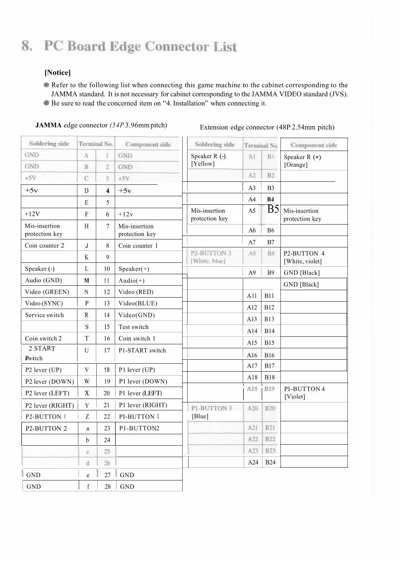
Refer to the following list when connecting this game machine to the cabinet corresponding to theJAMMA standard. It is not necessary for cabinet corresponding to the JAMMA VIDEO standard (JVS).Be sure to read the concerned item on “4. Installation” when connecting it.
JAMMA edge connector (54P 3.96mm pitch) Extension edge connector (48P 2.54mm pitch)
Speaker R (+)[Orange]
Speaker R (-)[Yellow]
I A3 B3
A4 B4
Mis-insertion A5 B5protection key
A6 B6
Mis-insertionprotection key
A7 B7
P2-BUTTON 4[White, violet]
GND [Black]
GND [Black]
A9 B9
Video (SYNC) P 13 Video(BLUE)
A14 B14
A15 B15
switchP
2
-
START U 17 P1-START switch I A16 B16
i i PI-BUTTON 4[Violet]P2 lever (LEFT) x 20 PI lever (LEFT)
P2 lever (RIGHT) Y 21 P1 lever (RIGHT)
P2-BUTTON Z 22 PI-BUTTON [Blue]
GND e 27 GND
GND f 28 GND


