34
OWNER'S MANUAL MANUAL DEL PROPIETARIO

OM11-0108-08E,S
OWNER'S MANUALMANUAL DEL PROPIETARIO
HEAD OFFICE(FACTORY)OFICINA CENTRAL (FÁBRICA)#58, SUNG SAN-DONG, CHANG WON, KYUNGNAM, KOREATEL: (82-55) 239-7000 / FAX: (82-55) 239-7524

CONTENTS
1. SPECIFICATION.................................................... 3
2. OPERATION2-1. FUEL COCK...................................................... 52-2. FILLING OF FUEL AND ENGINE OIL........ 52-3. IGNITION KEY..................................................62-4. STARTING......................................................... 72-5. CHECK POINTS WHEN ENGINE FAILS
TO START.......................................................... 92-6. DRIVING OFF................................................. 102-7. DRIVING ON SLOPES.................................. 112-8. BRAKING........................................................ 122-9. TURN SIGNALS AND HORN ..................... 132-10. HEAD LIGHT AND TAIL & STOP
LIGHT............................................................... 142-11. SPEEDOMETER & ODOMETER................ 15
3. CHECK POINTS FOR MAXIMUM PERFORMANCE
3-1. DAILY CHECK............................................... 163-2. REGULARLY SCHEDULED CHECK........ 17
CONTENIDO
1. ESPECIFICACIONES ........................................... 3
2. OPERACIÓN2-1. LLAVE DE COMBUSTIBLE.......................... 52-2. LLENADO DE COMBUSTIBLE Y
ACEITE DEL MOTOR..................................... 52-3. LLAVE DE ENCENDIDO ............................... 62-4. ARRANQUE...................................................... 72-5. PUNTOS A REVISAR SI HAS FALLOS
EN EL MOTOR................................................. 92-6. ARRANQUE.................................................... 102-7. MANEJO EN PENDIENTES......................... 112-8. FRENOS........................................................... 122-9. GUIÑADORES Y BOCINA.......................... 132-10. LUCES DELANTERA, TRASERA Y DE
PARADA.......................................................... 142-11. VELOCIMETRO Y ODOMETRO ............... 15
3. PUNTOS A REVISAR POR MAXIMORENDIMIENTO
3-1. REVISIÓN DIARIA........................................ 163-2. REVISIONES REGULARES
PROGRAMADAS .......................................... 17
- 1 -
LIBERTY 02.11.5 5:44 PM 페이지1

CONTENTS
4. MAINTENANCE AND LUBRICATION4-1. ENGINE OIL ................................................... 184-2. GEAR OIL........................................................ 194-3. SPARK PLUG.................................................. 214-4. FUEL COCK.................................................... 224-5. AIR CLEANER ............................................... 234-6. THROTTLE CABLE ADJUSTMENT......... 244-7. CARBURETOR ADJUSTMENT.................. 254-8. BRAKE ADJUSTMENT................................ 264-9. DRIVE CHAIN................................................ 274-10. BATTERY ........................................................ 294-11. FUSE REPLACEMENT................................. 304-12. IGNITION TIME............................................. 314-13. MUFFLER........................................................ 314-14. CUMBUSTION CHAMBER
DECARBONIZING........................................ 32
CONTENIDO
4. MANTENIMIENTO Y LUBRICACIÓN4-1. ACEITE DEL MOTOR .................................. 184-2. ACEITE DE LA CAJA DE CAMBIOS........ 194-3. BUJÍA DE ENCENDIDO............................... 214-4. LLAVE DE COMBUSTIBLE........................ 224-5. LIMPIADOR DE AIRE.................................. 234-6. AJUSTE DEL CABLE DEL OBTURADOR... 244-7. AJUSTE DEL CARBURADOR.................... 254-8. AJUSTE DEL FRENO.................................... 264-9. CADENA ......................................................... 274-10. BATERÍA ......................................................... 294-11. REEMPLAZO DEL FUSIBLE...................... 304-12. TIEMPO DE IGNICIÓN ................................ 314-13. SILENCIADOR............................................... 314-14. DECARBONIZACIÓN DE LA
CAMARA DE COMBUSTIBLE .................. 32
- 2 -
LIBERTY 02.11.5 5:44 PM 페이지2

1. SPECIFICATION 1. ESPECIFICACIONES
- 3 -
ITEM
TYPE
BORE AND STROKE
PISTON DISPLACEMENT
COMPRESSION RATIO
CARBURETOR
IGNITION TYPE
OIL CAPACITY
PS/RPM.
TORQUE/RPM.
STARTING SYSTEM
CLUTCH SYSTEM
TYPE
PRIMARY DRIVE
GEAR RATIO 1
GEAR RATIO 2
FINAL DRIVE
40 X 39.5mm
49.6cc
6.5:1
VM 13(LEADED/UNLEADED)
POINTLESS
1.2 ℓ
3/6,000
0.36/6,000
KICK/ELECTRIC
CENTRIFUGAL AUTOMATIC
AUTOMATIC 2 SHIFT
4,353
1,350
2,750
3,667
AIR-COOLED, ONECYLINDER, 2 STROKE
EN
GIN
ET
RA
NSM
ISSION
DATA CARACTERÍSTICA
TIPO
DIAMETRO Y CARRERA
DESPLAZAMIENTO DEL PISTON
RAZON DE COMPRESIÓN
CARBURADOR
TIPO DE IGNICIÓN
CAPACIDAD DE ACEITE
PS/RPM
TORQUE/RPM
SISTEMA DE ARRANQUE
SISTEMA DE EMBRAGUE
TIPO
PROPULSIÓN PRIMARIA
RAZON DE ENGRANAJES 1
RAZON DE ENGRANAJES 2
PROPULSIÓN FINAL
40 X 39.5mm
49.6cc
6.5:1
VM 13(PLOMO/SIN PLOMO)
SIN AGUJAS
1.2 ℓ
3/6,000
0.36/6,000
RÁPIDO / ELECTRICO
CENTRIFUGO AUTOMATICO
AUTOMATICO, 2 CAMBIOS
4,353
1,350
2,750
3,667
UN CILINDRO, ENFRIADOPOR AIRE, DOS TIEMPOS
MO
TO
RT
RA
NSM
ISIÓN
DATOA
LIBERTY 02.11.5 5:44 PM 페이지3

1. SPECIFICATION 1. ESPECIFICACIONES
- 4 -
ITEM
TYPE
WHEEL BASE
SEAT HEIGHT
GROUND CLEARANCE
FUEL CAPACITY
RAKE/TRAIL
OVERALL LEG X WDT X HGT
POWER SOURCE
CHARGE CONTROL
BATTERY CAPACITY
SUSPENSION
BRAKE
TIRE
FR.
RR.
FR.
RR.
FR.
RR.
TUBULAR
1,150mm
750mm
TELESCOPIC
SWING ARM (OIL)
DRUM BRAKE
DRUM BRAKE
2,25 X 17″
2.25 X 17″
140mm
5.5ℓ
64˚ / 70mm
1,790 X 685 X 1,020 mm
12V
REGULATOR RECTIFIER
12V4AH
CH
ASSIS
EL
E.
DATA CARACTERÍSTICA
TIPO
BASE DE LA RUEDA
ALTURA DEL ASIENTO
ESPACIO LIBRE
CAPACIDAD COMBUSTIBLE
RASTRO/COLA
LARGO X ANCHO X ALTURA
FUENTE DE POTENCIA
CONTROL DE CARGA
CAPACIDAD DE BATERÍA
SUSPENSIÓN
FRENOS
NEUMATICO
DELANTERO
TRASERO
DELANTERO
TRASERO
DELANTERO
TRASERO
TUBULAR
1,150mm
750mm
TELESCÓPICO
BRAZO L’OCO
ZAPATA DEL FRENO
ZAPATA DEL FRENO
2,25 X 17″
2.25 X 17″
140mm
5.5ℓ
64˚ / 70mm
1,790 X 685 X 1,020 mm
12V
RECTIFICADOR DEL REGULADOR
12V4AH
CH
ASIS
ELÉCTRICO
DATOA
LIBERTY 02.11.5 5:44 PM 페이지4
- 5 -
2. OPERATION
2-1 FUEL COCK
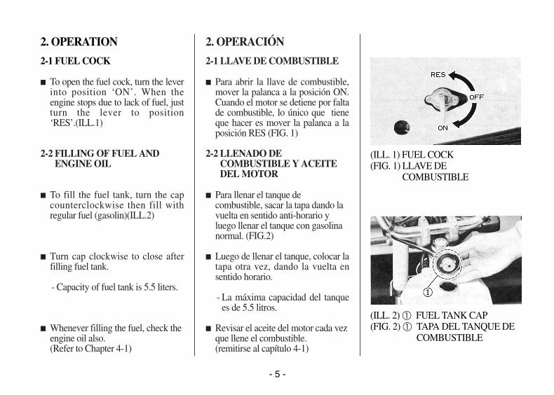
� To open the fuel cock, turn the leverinto position ‘ON’. When theengine stops due to lack of fuel, justturn the lever to position‘RES’.(ILL.1)
2-2 FILLING OF FUEL ANDENGINE OIL
� To fill the fuel tank, turn the capcounterclockwise then fill withregular fuel (gasolin)(ILL.2)
� Turn cap clockwise to close afterfilling fuel tank.
- Capacity of fuel tank is 5.5 liters.
� Whenever filling the fuel, check theengine oil also.(Refer to Chapter 4-1)
2. OPERACIÓN
2-1 LLAVE DE COMBUSTIBLE
� Para abrir la llave de combustible,mover la palanca a la posición ON.Cuando el motor se detiene por faltade combustible, lo único que tieneque hacer es mover la palanca a laposición RES (FIG. 1)
2-2 LLENADO DECOMBUSTIBLE Y ACEITEDEL MOTOR
� Para llenar el tanque decombustible, sacar la tapa dando lavuelta en sentido anti-horario yluego llenar el tanque con gasolinanormal. (FIG.2)
� Luego de llenar el tanque, colocar latapa otra vez, dando la vuelta ensentido horario.
- La máxima capacidad del tanquees de 5.5 litros.
� Revisar el aceite del motor cada vezque llene el combustible.(remitirse al capítulo 4-1)
(ILL. 1) FUEL COCK(FIG. 1) LLAVE DE
COMBUSTIBLE
(ILL. 2) ① FUEL TANK CAP (FIG. 2) ① TAPA DEL TANQUE DE
COMBUSTIBLE
LIBERTY 02.11.5 5:44 PM 페이지5
- 6 -
2-3 IGNITION KEY
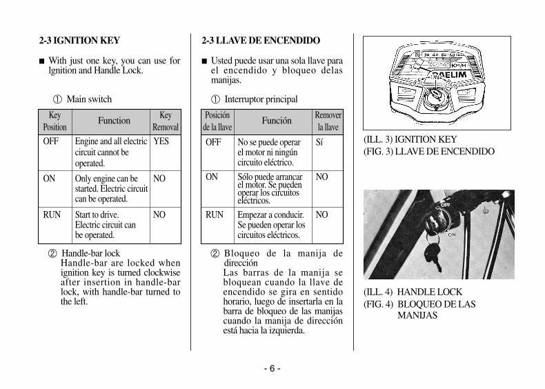
� With just one key, you can use forlgnition and Handle Lock.
① Main switch
② Handle-bar lockHandle-bar are locked whenignition key is turned clockwiseafter insertion in handle-barlock, with handle-bar turned tothe left.
2-3 LLAVE DE ENCENDIDO
� Usted puede usar una sola llave parael encendido y bloqueo delasmanijas.
① Interruptor principal
② Bloqueo de la manija dedirecciónLas barras de la manija sebloquean cuando la llave deencendido se gira en sentidohorario, luego de insertarla en labarra de bloqueo de las manijascuando la manija de direcciónestá hacia la izquierda.
(ILL. 3) IGNITION KEY(FIG. 3) LLAVE DE ENCENDIDO
(ILL. 4) HANDLE LOCK (FIG. 4) BLOQUEO DE LAS
MANIJAS
Key Function KeyPosition Removal
OFF Engine and all electric YEScircuit cannot beoperated.
ON Only engine can be NOstarted. Electric circuitcan be operated.
RUN Start to drive. NOElectric circuit canbe operated.
Posición Función Removerde la llave la llave
OFF No se puede operar Síel motor ni ningúncircuito eléctrico.
ON Sólo puede arrancar NOel motor. Se pueden operar los circuitoseléctricos.
RUN Empezar a conducir. NOSe pueden operar loscircuitos eléctricos.
LIBERTY 02.11.5 5:44 PM 페이지6

- 7 -
2-4. STARTING
� Turn the fuel cock lever into ‘ON’position. (ILL.5)
� Turn the ignition key to ‘ON’position. (ILL.6)
2-4. ARRANQUE
� Mover la palanca a la posición ON(FIG. 5)
� Girar la llave de encendido a laposición ON.(FIG. 6)
(ILL. 5) FUEL COCK LEVER(FIG. 5) PALANCA DE LA LLAVE
DE COMBUSTIBLE
(ILL. 6) IGNITION KEY (FIG. 6) LLAVE DE ENCENDIDO
LIBERTY 02.11.5 5:44 PM 페이지7
- 8 -
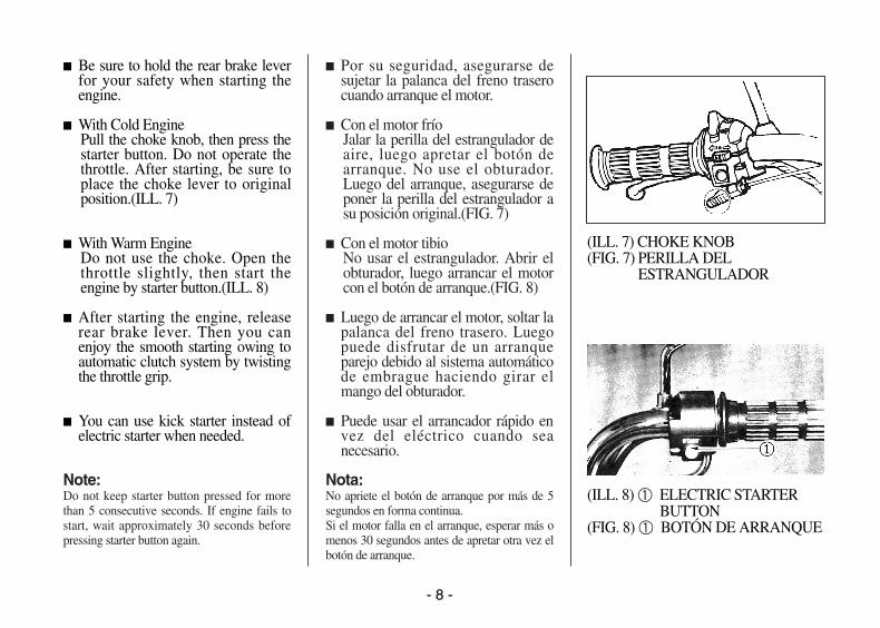
� Be sure to hold the rear brake leverfor your safety when starting theengine.
� With Cold EnginePull the choke knob, then press thestarter button. Do not operate thethrottle. After starting, be sure toplace the choke lever to originalposition.(ILL. 7)
� With Warm EngineDo not use the choke. Open thethrottle slightly, then start theengine by starter button.(ILL. 8)
� After starting the engine, releaserear brake lever. Then you canenjoy the smooth starting owing toautomatic clutch system by twistingthe throttle grip.
� You can use kick starter instead ofelectric starter when needed.
Note:Do not keep starter button pressed for morethan 5 consecutive seconds. If engine fails tostart, wait approximately 30 seconds beforepressing starter button again.
� Por su seguridad, asegurarse desujetar la palanca del freno traserocuando arranque el motor.
� Con el motor fríoJalar la perilla del estrangulador deaire, luego apretar el botón dearranque. No use el obturador.Luego del arranque, asegurarse deponer la perilla del estrangulador asu posición original.(FIG. 7)
� Con el motor tibioNo usar el estrangulador. Abrir elobturador, luego arrancar el motorcon el botón de arranque.(FIG. 8)
� Luego de arrancar el motor, soltar lapalanca del freno trasero. Luegopuede disfrutar de un arranqueparejo debido al sistema automáticode embrague haciendo girar elmango del obturador.
� Puede usar el arrancador rápido envez del eléctrico cuando seanecesario.
Nota:No apriete el botón de arranque por más de 5segundos en forma continua.Si el motor falla en el arranque, esperar más omenos 30 segundos antes de apretar otra vez elbotón de arranque.
(ILL. 7) CHOKE KNOB(FIG. 7) PERILLA DEL
ESTRANGULADOR
(ILL. 8) ① ELECTRIC STARTERBUTTON
(FIG. 8) ① BOTÓN DE ARRANQUE
LIBERTY 02.11.5 5:44 PM 페이지8

2-5 CHECK POINTS WHENENGINE FAILS TO START
1) Fuel level in fuel tank.
2) Electric starter ; Starter motor, button, battery.
3) Contamination of carburetor.
4) Contamination of air cleaner element.
5) Contamination of spark plug and clearance of electrodesof spark plug
6) Clogging at fuel cock or in fuel line
2-5 PUNTOS A REVISAR SI HASFALLOS EN EL MOTOR
1) Nivel de combustible en el tanque
2) Arrancador eléctrico ; motor, botón de arranque, batería
3) Contaminación en el carburador
4) Contaminación del elemento limpiador de aire
5) Contaminación y separación de los electrodos en la bujíade encendido
6) Obstrucción en la llave o línea de combustible
- 9 -
AVOID RUNNING THE ENGINE FOR LONGPERIODS WHEN YOUR MOTORBIKE ISSTATIONARY.OTHERWISE, ENGINE WILL BE ADVERSELYAFFECTED AND FUEL WASTED.
EVITAR TENER EL MOTOR ENCENDIDOPOR LARGO TIEMPO CUANDO SU MOTOCI-CLETA ESTA PARADA, DE OTRAMANERA EL MOTOR SERA AFECTADO YSE DESPERDICIARA EL COMBUSTIBLE.
LIBERTY 02.11.5 5:44 PM 페이지9

2-6 DRIVING OFF
� Liberty has an automatic clutch for easier driving-off.
� Motorbike will pull smoothly away when throttle grip isturned slowly.
[Advantages]Automatic transmission
� Speed of motorbike will increased smoothly as 2nd gear isautomatically engaged when speed rises above 30km/hafter driving off.
� When driving up a steep hill, a powerful driving force willbe obtained when 1st gear is automatically engaged aftertravel speed is reduced below 35km/h.
2-6 ARRANQUE
� El modelo Liberty tiene un sistema de embragueautomático para un arranque fácil.
� Cuando gire lentamente la manija del obturador, lamotocicleta arrancará suavemente.
[Ventajas]Transmisión automática
� Luego de arrancar la motocicleta, su velocidad aumentaráuniformemente y pasará automáticamente a segunda alllegar a los 30km/h.
� Al subir una cuesta, se obtendrá la potencia necesaria parala subida al pasar automáricamente a primera cuando lavelocidad baje a menos de 35km/h.
- 10 -
LIBERTY 02.11.5 5:44 PM 페이지10

- 11 -
2-7 DRIVING ON SLOPES
Uphill
When driving uphill, turn acceleratorgrip slowly to maintain engine speedflexibility, whereupon 1st gear or 2ndgear is automatically engagedaccording to degree of slope and speedof motorbike, providing a comfortableride.
Downhill
When driving downhill, completelyshut off accelerator grip, applyingfront and rear brakes slowly.
2-7 MANEJO EN PENDIENTES
Cuesta arriba
Cuando conduzca cuesta arriba, girarla manija del acelerador lentamente afin de mantener la flexibilidad delmotor, luego de lo cual el cambio deprimera a segunda se hará en formaautomática de acuerdo a la inclinaciónde la pendiente y la velocidad de lamotocicleta, proporcionando así unmanejo cómodo.
Cuesta abajo
Cuando conduzca cuesta abajo,disminuya la velocidad aplicandolentamente presión a los frenosdelantero y trasero.
LIBERTY 02.11.5 5:44 PM 페이지11

2-8 BRAKING
� Practice stopping with either brakes.Use both front and rear brakes for maximum brakingefficiency and for your safety.For stopping, you just close the throttle. Then the enginewill continue to run idle speed,and turn the ignition key to‘OFF’ position via ‘ON’ position from ‘RUN’position.Close the fuel cock.
2-8 FRENOS
� Practicar el frenado con ambos frenos.Use ambos frenos, delantero y trasero, para una máximaeficiencia en el frenado y seguridad suya.Para detener la motocicleta, solamente cierre el obturador.Entonces el motor continuará en marcha lenta, ponga lallave de ignición en la posición OFF y cierre la llave decombustible.
- 12 -
CHECK BRAKE EVERY TIME BEFORE YOURIDE MOTORBIKE.
REVISAR LOS FRENOS CADA VEZ QUEMANEJE LA MOTOCICLETA.
LIBERTY 02.11.5 5:44 PM 페이지12

- 13 -
2-9 TURN SIGNALS AND HORN
� During riding, you can simplyoperate turn signal lights by usingthe switch on left handle leverholder. Also you can see blinkingindicator lamps on speedometerpanel which blinks according toyour turning direction. (ILL. 11)
� You can easily sound the horn bypressing the horn button on lefthandle lever holder. (ILL. 11)
※Battery power will be wasted ifhorn is over-used.
2-9 GUIÑADORES Y BOCINA
� Cuando conduzca, usted puedeoperar fácilmente los guiñadoresusando el interruptor en la palancade la manija izquierda. Además,puede ver las luces indicadoras dedirección en el panel delvelocímetro las cuales parpadean deacuerdo con la dirección deizquierda. (FIG. 11)
� También puede hacer sonar labocina apretando el botón de labocina en la palanca de la manijaderecha. (FIG. 11)
※El exceso de uso de la bocinadesperdiciará la potencia de labatería.
(ILL. 11) ①HORN BUTTON②TURN SIGNAL S/W
(FIG. 11) ①BOTÓN DEL BOCINA.
②INTERRUPTOR DELGUIÑADOR
LIBERTY 02.11.5 5:44 PM 페이지13

- 14 -
2-10 HEAD LIGHT AND TAILAND STOP LIGHT
� On the left handle lever holder, youcan use head light switch for night-time driving.(ILL.12)
� During running stop light will belighted by holding one of both leftand right brake lever.
� Whenever head light switch isturned on, tail light is also turnedon.
2-10 LUCES DELANTERA,TRASERA Y DE PARADA
� Para manejar de noche, puedeencender la luz delantera utilizandoel interruptor ubicado en la palancade la manija izquierda.(FIG. 12)
� Cuando esté conduciendo, la luz deparada se encenderá al apretar unade las manijas de freno, ya sea laderecha o izquierda.
� Cuando se enciende la luz delantera,la luz trasera se encenderá también.
(ILL. 12) ①HEAD LIGHT S/W(FIG. 12) ①INTERRUPTOR DE LA
LUZ DELANTERA
LIBERTY 02.11.5 5:44 PM 페이지14

- 15 -
2-11 SPEEDOMETER ANDODOMETER
� You can easily find out the runningspeed by the speedometer.The maximum speed shown onspeedometer is 70km/h. The RedColored Zone over 40 km/h warnsdangerous speed for your safedriving.(ILL. 13)
� Speedometer will be illuminatedfor easier reading when headlightis turned on when driving in night.
� Regular service periods can beconfirmed with the odometerenclosed in the speedometer dial,as the former shows total distancetravelled.
2-11 VELOCIMETRO YODÓMETRO
� Se puede saber fácilmente lavelocidad a la que se está con-duciendo usando el velocímetro.La velocidad máxima mostrada esde 70km/h. La zona coloreada enrojo sobre 40km/h advierte alconductor sobre velocidarespeligrosas para un manejoseguro.(FIG. 13)
� Al conducir de noche, el panelmedidor se iluminará para unafácil lectura cuando encienda laluz delantera.
� Se pueden confirmar los períodosde servicio a la máquinachequeando el odómetro quemuestra la distancia totalrecorrida.
(ILL. 13) SPEEDOMETER(FIG. 13) VELOCIMETRO
LIBERTY 02.11.5 5:44 PM 페이지15

3. CHECK POINTS FOR MAXIMUMPERFORMANCE
3-1 DAILY CHECK
1. Engine oil level in oil tank.2. Gear oil level in transmission
·Use SAE 15W/40 oil·Q'ty : 150cc
3. Fuel level in fuel tank4. Air pressure in tire
·Front : 1.75kg/㎠·Rear : 2.0kg/㎠
5. Front & rear brake6. Electric equipment
·Head light, horn, turn signals and tail & stop lights7. Drive chain lubrication8. Handle operation9. Back mirror adjustment10. Fitness of important bolts & nuts11. Battery electrolyte12. Throttle grip operation
3. PUNTOS A REVISAR POR MAXIMORENDIMIENTO
3-1 REVISIÓN DIARIA
1. Nivel del aceite de motor en el tanque de aceite.2. Nivel de aceite de la caja de cambios.
·Use aceite SAE 15W/40·Cantidad : 150cc
3. Nivel de combustible en el tanque.4. Presión de aire en los neumáticos.
·Delantero : 1.75kg/㎠·Trasero : 2.0kg/㎠
5. Frenos delantero y trasero.6. Equipo eléctrico
·Luz delantera, bocina, guiñadores y luces trasera y deparada.
7. Lubricación de la cadena.8. Operación de las manijas.9. Ajuste del espejo retrovisor.10. Ajuste de pernos y tuercas importantes.11. Electrólito de la batería.12. Operación del control del obturador.
- 16 -
LIBERTY 02.11.5 5:44 PM 페이지16

3-2 REGULARLY SCHEDULED CHECK 3-2 REVISIONES REGULARES PROGRAMADAS
- 17 -
SERVICEPERIODS
ITEM
500
km
1
MON
2
MON
4
MON
6
MON
8
MON
10
MON
12
MON
14
MON
16
MON
18
MON
20
MON
22
MON
24
MON
Brake ○ ○ ○ ● ○ ○ ● ○ ○ ● ○ ○ ●
○ ○ ○ ● ○ ○ ● ○ ○ ● ○ ○ ●
● ● ●
○ ○ ○ ○ ○
● ● ● ● ●
○ ○ ○ ○ ○ ●
● ● ● ●
● ● ● ● ●
● ○ ○ ○ ○ ○ ○ ●
● ● ● ●
○ ○ ○ ○ ○ ○ ○ ● ○ ○ ○ ○ ○ ●
Battery
Gear Oil
Spark Plug
Carburetor
Air Cleaner
Decarbonizationof Engine
Drive ChainAdjustment
Muffler Cleaning
Grease Lubrication
Bolt & Nuts Fitness
● Check by Aurhorized Dealer○ Checked by Owner
PERIODO DESERVICIO
PIEZA
500
km
1
MES
2
MES
4
MES
6
MES
8
MES
10
MES
12
MES
14
MES
16
MES
18
MES
20
MES
22
MES
24
MES
Frenos ○ ○ ○ ● ○ ○ ● ○ ○ ● ○ ○ ●
○ ○ ○ ● ○ ○ ● ○ ○ ● ○ ○ ●
● ● ●
○ ○ ○ ○ ○
● ● ● ● ●
○ ○ ○ ○ ○ ●
● ● ● ●
● ● ● ● ●
● ○ ○ ○ ○ ○ ○ ●
● ● ● ●
○ ○ ○ ○ ○ ○ ○ ● ○ ○ ○ ○ ○ ●
Batería
Aceite de la caja de cambios
Bujía de encendido
Carburador
Limpiador de aire
Decarbonizacióndel motor
Ajuste de lacadena
Limpieza del ailenciador
Lubricación
Ajuste de perpos y tuercas
● Revisado por distribuidor autorizado.○ Revisado por el propietario.
LIBERTY 02.11.5 5:44 PM 페이지17

- 18 -
4. MAINTENANCE ANDLUBRICATION
4-1 ENGINE OIL
� Before your first riding afterpurchase, be sure to fill engine oil inoil tank under the seat. (ILL. 14)
� Recommend you to use DAELIM 2stroke motorcycle oil or it’sequivalant.
� Remember to supply engine oilwhen remainder is about a quarterof oil tank capacity.
� Always use same brand oil to avoidany trouble.
� If necessary to change to anotherbrand, drain remaining old oilthoroughly then fill with new brandoil.
4. MANTENIMIENTO YLUBRICACIÓN
4-1 ACEITE DEL MOTOR
� Luego de la compra, y antes deconducir la motocicleta por primeravez, asegurarse de llenar el tanque deaceite debajo del asiento.(FIG. 14)
� Se recomienda utilizar aceite paramotocicletas de dos tiemposDAELIM o su equivalente.
� Recuerde llenar nuevamente letanque de aceite, cuando esté a uncuarto de su capacidad.
� Siempre use la misma marca deaceite a fin de evitar cualquierproblema.
� Si necesita cambiar a otra marca deaceite, purgar totalmente el aceite“viejo” y luego llene el tanque conel “nuevo” aceite.
(ILL. 14) ①OIL TANK CAP.(FIG. 14) ①TAPA DEL TANQUE
ACEITE.
LIBERTY 02.11.5 5:44 PM 페이지18

- 19 -
4-2 GEAR OIL
� To drain, remove right side coverthen open the oil cap. Open thedrain bolt. (ILL. 16, 17)
※When engine is warmed, drainagecan be carried out very quickly.
� 2 STROKE MOTORCYCLE OILUSE ONLY!
� ÍSE USE ACEITE PARA MOTORDE 2 TIEMPOS SOLAMENTE!
4-2 ACEITE DE LA CAJA DECAMBIOS
� Para purgar el aceite, remover lacubierta del costado derecho y abrirla tapa del aceite. Abrir el perno depurga. (drenaje)(FIG. 16, 17)
※ Se puede llevar a cabo rápidamentela purga cuando el motor esté tibio.
(ILL. 16) ①OIL CAP.(FIG. 16) ①TAPA DEL ACEITE.
(ILL. 17) ①DRAIN BOLT②SCREW
(FIG. 17) ①PERNO DE PURGA②TORNILLO
LIBERTY 02.11.5 5:44 PM 페이지19

- 20 -
� To supply the gear oil, screw thedrain bolt first then fill SAE 15 W40 oil (Q’ty 150cc)into the oil caphole. Check through oil levelhole.(ILL. 18)
※Always use genuine DAELIM oil inorder to lengthen the life of themotorbike.
� Para llenar el aceite de la caja decambios, atornillar el perno depurga y luego llenar con aceite SAE15W40 (Cantidad: 150 cc) en elorificio de la tapa del aceite. Revisarel nivel mediante el orificio de nivelde aceite. (FIG.18)
※Usar siempre el aceite DAELIMgenuino a fin de prolongar la vidade la motocicleta. (ILL. 18) ①OIL LEVEL HOLE.
(FIG. 18) ①ORIFICIO DE NIVELDE ACEITE.
LIBERTY 02.11.5 5:44 PM 페이지20

- 21 -
4-3 SPARK PLUG
1. Note that sparks can not bedischarged when the electrodes arecontaminated or wet with mixedgas.
2. Clean with plug cleaner. If plugcleaner is not available, decarbonizethe electrodes with wire brush.
3. Normal clearance betweenelectrodes: 0.6~0.7mm (ILL. 19)
� Every 1,500km riding, check andclean the spark plug. If necessary,change with a new one. (ILL. 20)
� Standard spark plug: Golden B6HS
4-3 BUJÍA DE ENCENDIDO
1. Notar que las chispas no puedendescargarse cuando los electrodosestán contaminados o humedecidoscon una mezcla de gases.
2. Limpiar con un limpia bujías. Si notiene uno, decarbonizar loselectrodos con una escobilla dealambre.
3. La distancia normal entre loselectrodos es de 0.6~0.7 mm.(FIG. 19)
� Luego de cada 1,500 km de manejo,revisar y limpiar la bujía. Si esnecesario cambiar por unanueva.(FIG.20)
� Bujía de encendido estándar:Golden B6HS
(ILL. 19) SPARK PLUG(FIG. 19) BUJÍA DE ENCENDIDO
(ILL. 20)(FIG. 20)
Normal clearance:0.6-0.7 mm(0.024-0.028″)
Distancia normal0.6-0.7 mm(0.024-0.028 in)
Clean
Limpiar
LIBERTY 02.11.5 5:44 PM 페이지21

- 22 -
4-4 FUEL COCK
To supply the clean fuel there is filterelement in fuel cock.
� Cleaning procedure ;
1. Drain the fuel from the fuel tank.
2. Disconnect the fuel tube andremove the fuel cock.
3. Remove the filter element and O-ring in the plastic cap.
4. Remove the lever from the cockbody.
5. Clean the cap and filter elementwith solvent or gasolin.
6. Clean the fuel passages withcompressed air.
7. Check the gasket. If defected,replace with a new one.
4-4 LLAVE DE COMBUSTIBLE
Para alimentar al motor uncombustible limpio, hay un filtro en lallave de combustible.
� Procedimiento de limpieza ;
1. Purgar el combustible del tanque.
2. Desconectar el tubo de combustibley sacar la llave de combustible.
3. Remover el filtro y el anillo-O en latapa de plástico.
4. Remover la palanca de la llave.
5. Limpiar la tapa y el filtro congasolina o un solvente.
6. Limpiar los ductos de combustiblecon aire comprimido.
7. Revisar la empaquetadura, si estádefectuosa, reemplazar con unanueva.
(ILL. 21) FUEL COCK(FIG. 21) LLAVE DE
COMBUSTIBLE
LIBERTY 02.11.5 5:44 PM 페이지22

- 23 -
4-5 AIR CLEANER
� Maintain the air cleaner cleanalways. Contaminated air cleanergives bad effect on engineperformance.
� Cleaning procedure
1. Disassemble right/left side coverand upper cover.
2. Remove the bolt and connectingtube band then remove the aircleaner. (ILL. 22)
3. Remove the screw, then remove theelement.
4. Wash the element with solvent orgasoline. (ILL. 23)
5. Clean the inside of air cleaner case.
6. After element is dried, soak it withgear oil. Then squeeze it to removethe excess.
7. Perform assembly in reverse orderto disassembly.
4-5 LIMPIADOR DE AIRE
� Mantener siempre el aire limpio. Unlimpiador de aire contaminado causaun mal efecto en el rendimiento delmotor.
� Procedimiento de limpieza
1. Sacar las cubiertas derechaizquierda y superior.
2. Sacar el perno y la banda,removiendo luego el limpiador deaire. (FIG. 22)
3. Sacar el tornillo y luego el elementolimpiador. (FIG. 23)
4. Lavar el elemento limpiador congasolina o un solvente.
5. Limpiar el interior de la caja dellimpiador de aire.
6. Luego que el elemento se ha secado,remojarlo con aceite para la caja decambios. Luego, apretar para quitarel exceso de aceite.
7. Hacer el montaje en el ordeninverso al desmontaje.
(ILL. 22) ① BOLT② SCREW
(FIG. 22) ① PERNO② TORNILLO
(ILL. 23) AIR CLEANER ELEMENT(FIG. 23) ELEMENTO DE AIRE
LIMPIADOR
LIBERTY 02.11.5 5:44 PM 페이지23

- 24 -
4-6 THROTTLE CABLE ADJUSTMENT
1. Remove the left side cover.
2. Adjust with the adjuster locatedupper part of carburetor. (ILL. 24)
3. Adjust with the adjuster locatedunder the throttle grip. (ILL. 25)
4. The free play of throttle cable is5mm.
4-6 AJUSTE DEL CABLE DELOBTURADOR
1. Remover la cubierta del ladoizquierdo.
2. Ajustar el cable con el ajustadorsituado en la parte superior delcarburador. (FIG. 24)
3. Ajustar el cable con el ajustadorsituado debajo del mango delobturador. (FIG. 25)
4. La holgura del cable del obturadores de 5mm.
(ILL. 24) ① ADJUSTER(FIG. 24) ① AJUSTADOR
(ILL. 25) ① ADJUSTER(FIG. 25) ① AJUSTADOR
LIBERTY 02.11.5 5:44 PM 페이지24

- 25 -
4-7 CARBURETOR ADJUSTMENT
1. Turn the air screw until it stops.Then unscrew 1½ turns. (ILL. 26)
2. Start the engine and make itwarmed.
3. Turn the throttle stop screw untilidle speed marks minimum.
4. Then adjust air screw until idlespeed marks maximum.
5. Adjust idle speed with the throttlestop screw.Idle speed: 1400±100RPM.
4-7 AJUSTE DEL CARBURADOR
1. Girar el tornillo de aire hasta que sedetenga, luego darle una vuelta ymedia. (FIG. 26)
2. Arrancar el motor y calentarlo.
3. Girar el tornillo de parada delobturador hasta que la velocidad enmarcha lenta marque un mínimo.
4. Ajustar el tornillo de aire hasta quela velocidad en marcha lenta 1leguea un máximo.
5. Ajustar la marcha lenta con eltornillo de parada del obturador.Marcha lenta: 1,400±100 RPM
(ILL. 26) ① THROTTLE STOP SCREW
② AIR SCREW(FIG. 26) ① TORNILLO DE
AJUSTE DELOBTURADOR
② TORNILLO DE AIRE
LIBERTY 02.11.5 5:44 PM 페이지25

- 26 -
4-8 BRAKE ADJUSTMENT
� The free play of front and rear brakelever is 15-20mm after adjustment.Check the operation of stop light.(ILL. 27)
� Always use front and rear braketogether for safety.
4-8 AJUSTE DE LOS FRENOS
� La holgura de la palanca de losfrenos delantero y trasero es de 15-20 mm luego del ajuste. Revisar laoperación de las luces de parada.(FIG. 27)
� Siempre use juntos los frenosdelanteroy trasero para suseguridad.
YOUR LIFE ISDEPENDENT ON GOODBRAKE PERFORMANCE.ALWAYS CHECK THEBRAKES BEFOREDRIVING.
SU VIDA DEPENDE DELBUEN RENDIMIENTO DELOS FRENOS.REVISAR SIEMPRE LOS FRENOS ANTES DE CONDUCIR.
(ILL. 27) BRAKE LEVER(FIG. 27) PALANCA DE
FRENO
LIBERTY 02.11.5 5:44 PM 페이지26

- 27 -
4-9 DRIVE CHAIN
To adjust
The drive chain slack should beadjusted to allow 10-20mm verticalmovement by hand. (ILL. 28)
1. Loosen the rear axle nut.
2. Turn the adjusting nut on both theright and left chain adjusters anequal amount to increase ordecrease chain slack. Align thechain adjuster index mark withcorresponding scale graduations onboth sides of the swing arm. (ILL. 29)
4-9 CADENA
Para ajustar la cadena
La tirantez de la cadena debe serajustada a fin de permitir unmovimiento vertical de 10-20 mm conla mano. (FIG. 28)
1. Aflojar la tuerca del eje trasero.
2. Girar la tuerca de ajuste de losajustadores derecho e izquierdo dela cadena en igual proporción paraaumentar o disminuir la tirantez dela cadena. Alinear el ajustador de lacadena con las marcas en la escalagraduada a ambos lados del brazooscilante. (FIG. 29)
(ILL. 28) CHAIN SLACK(FIG. 28) TIRANTEZ DE LA
CADENA
(ILL. 29) ① ADJUSTER② AXLE NUT③ INDEX MARK
(FIG. 29) ① AJUSTADOR② TUERCA DEL EJE③ MARCA
LIBERTY 02.11.5 5:44 PM 페이지27

- 28 -
To clean
1. Remove the drive chain and washwith brush and solvent.
2. Dry the chain and be sure to avoidany dirts.
3. Boil in oil (50℃- 120℃) for about10 minutes.
4. Remove the oil with shop towel.
5. Lublicate with grease.Every 1,000km riding, cleaning thedrive chain is needed. Whenassembling the chain, be sure tocoincide direction of joint clip withthe rotation direction of chain. (ILL. 31)
Para limpiar cadena
1. Sacar la cadena y limpiarla con unaescobilla y solvente.
2. Secar la cadena y asegurarse de sulimpieza total.
3.Hacerlo hervir en aceite paraengranajes (50℃- 120℃) por más omenos 10 minutos.
4. Remover el aceite con una toalla.
5. Lubricar la cadena con grasa.Es necesaria hacer la limpieza de lacadena cada 1,000 Km. Cuandomonte la cadena, asegurarse dehacer coincidir la dirección del clipde unión con la dirección derotación de la cadena. (FIG. 31)
(ILL. 30)(FIG. 30)
(ILL. 31) JOINT CLIP(FIG. 31) CLIP DE UNION
Rotation directionDirección de rotación
LIBERTY 02.11.5 5:44 PM 페이지28

- 29 -
4-10 BATTERY
1. Remove right side cover.
2. Disconnect lead wire.
3. The electrolyte level must bemaintained between the upper andlower level marked on the side ofthe battery. If the electrolyte isdecreased, remove the battery fillercap (Yellow Colored).(ILL. 32)
4. Carefully add distilled water to theupper level mark.
5. Be sure to cut out the breather tubewhen using new battery. Use onlydistilled water in the battery. Tapwater will shorten the service life ofthe battery.
� Check whether bleeder tube is bentor clogged.
� If exterior of battery is stained withelectrolyte, it must be washed offwith water.
4-10 BATERÍA
1. Sacar la cubierta lateral derecha.
2. Desconectar el alambre de plomo.
3. El nivel de electrólito se debemantener entre las marcas superior e inferior situadas en el costado de la batería. Si ha disminuido el nivel de electrólito, remover la tapa dellenado de la batería (color amarillo). (FIG. 32)
4. Agregar cuidadosamente aguadestilada hasta el nivel de la marcasuperior.
5. Asegurarse de desconectar el tubodel respiradero cuando use unanueva batería. Usar solamente aguadestilada en la batería. El aguapotable normal acortará el tiempode vida útil de la batería.
� Revisar si el tubo de purga estáoxidado o bloqueado.
� Si el exterior de la batería estámanchado con electrolito, debe serlimpiado con agua.
(ILL. 32) ① UPPER LEVEL② LOWER LEVEL
(FIG. 32) ① NIVEL SUPERIOR② NIVEL INFERIOR
LIBERTY 02.11.5 5:44 PM 페이지29

- 30 -
4-11 FUSE REPLACEMENT
Fuse is inserted in battery holder.Fuse rating is 7A
� Attention1. Never use fuses other than fuses
of rated capacities. Otherwise,wiring may be burned.
2. If fuse is blown replace with newone after checking cause of fuse-blowing.
3. Do not spray water forcefullyaround fuse cover when cleaningmotorbike.
� RemovalPay attention not to leave holderopen. If fuse contact is notcomplete, with holder opened,problems may occur through heatbeing generated.
� InsertionCompletely insert fuse in holder.Confirm whether fuse can movehorizontally after insertion in holder.Unexpected problems may occurfrom moving fuse through heatgeneration.
4-11 REEMPLAZO DEL FUSIBLE
Insertar el fusible en el portafusible.El tipo de fusible es de 7A.
� Atención:1. No usar nunca fusibles de
capacidades diferentes a laspermitida, porque los cablespueden quemarse.
2. Si un fusible está quemado,reemplazarlo con uno nuevoluego de ver la causa de laquemadura del fusible.
3. No echar chorros potentes deagua alrededor de la cubierta delfusible cuando limpie lamotocicleta.
� RemociónPrestar atención en no dejar abiertoel portafusible. Si el contacto delfusible no es completo debido alportafusibles, pueden desarrollarseproblemas por el calor que segenera.
� InserciónInsertar completamente el fusible enel portafusibles.Confirmar si el fusible puedemoverse en forma horizontal luegode insertarlo en el portafusibles.Pueden ocurrir problemasinesperados debido a la generaciónde calor cuando el fusible se mueve.
[Removal ][Sacar] Fuse holder
Portafusible
Pull upJalar
Pull upJalar
ClipClip
Push to removeEmpujar para sacar
Push Empujar
[Insertion ][Insertat]
LIBERTY 02.11.5 5:44 PM 페이지30

- 31 -
4-12 IGNITION TIME
� It is not required to disassemblestator components in flywheel, asC.D.I. ignition system is used.
� Adjustment of ignition timing isnot recommended.If ignition timing is not correct,contact the nearest service stationfor checking and repair of ralatedfaulty parts.
4-13 MUFFLER
� Clean the carbon deposit of mufflerinside at proper period.(Within 5,000km riding)
1. Remove the locking nut anddisassemble the muffler cap.(ILL.34)
2. Turn noise suppressor capcounter-clockwise to remove.Then decarbonize with wirebrush.
4-12 TIEMPO DE IGNICIÓN
� No se requiere desarmar elcomponente del estator en la ruedavoladora dado que se usa el sistemade encendido C.D.I.
� No se recomienda el ajuste deltemporizador de la ignición.Si el tiempo de ignición no escorrecto, llamar a la estación deservicio más cercana para revisar ycambiar las partes defectuosas.
4-13 SILENCIADOR
� Limpiar el depósito de carbón en elsilenciador en un período apropiado(antes de los 5,000 Km).
1. Remover la tuerca de seguridad ydesmontar la tapa del silenciador. (FIG. 34)
2. Girar la tapa del supresor deruido en sentido antihorario parasacarla.Luego decarbonizar con unaescobilla de alambre
(ILL. 33) ① IGNITION TIME MARK(FIG. 33) ① MARCA DE IGNICIÓN
TIMPO
(ILL. 34) ① MUFFLER CAP② LOCKING NUT
(FIG. 34) ① TAPA DELSILENCIADOR
② TUERCA DE SEGURIDAD
LIBERTY 02.11.5 5:44 PM 페이지31

- 32 -
4-14 COMBUSTION CHAMBERDECARBONIZING
� Procedure1. Unscrew the cylinder head nuts.
2. Remove the cylinder head. (ILL. 35)
3. Remove the cylinder.4. Disassemble the piston.5. Decarbonize carbon deposit on
chamber inside with scraper andwire brush.
6. Clean the piston top with No 600sand paper.
Perform combustion chamberdecarbonizing within first 5,000kmtravel.
4-14 DECARBONIZACIÓN DE LACAMARA DECOMBUSTIBLE
� Procedimiento1. Sacar los tuercas del cabezal del
cilindro.2. Remover el cabezal del cilindro.
(FIG. 35)3. Remover el cilindro4. Desmontar el pistón5. Quitar los depósitos de carbón de
la cámara interior con unaescobilla de alambre y unraspador.
6. Limpiar el pistón con lija No. 600
Realizar la decarbonización de lacámara de combustión antes de losprimeros 5,000Km
(ILL. 35) CYLINDER HEAD(FIG. 35) CABEZAL DEL
CILINDRO
LIBERTY 02.11.5 5:44 PM 페이지32

OWNER’S MANUALMANUAL DEL PROPIETARIO
2001.8. PRINTEDIMPRESO
1995.1. PUBLICATIONPUBLICACÓN
NO COPY
LIBERTY 02.11.5 5:44 PM 페이지33


