24


Tel : +971 (2) 5502025 Tel : +971 (3) 7224768 Tel : +971 (4) 8858036 Tel : +971 (7) 2282332 Fax : +971 (2) 5502024 Fax :+971 (3) 7224769 Fax : +971 (4) 8858658 Fax : +971 (7)2282232 P.O. Box: 41558 P.O. Box: 99155 P.O. Box: 86029 P.O. Box: 33239 Abu Dhabi Al Ain Dubai Ras Al Khaimah
T R B L E O F C O n T E n T S
INTRODUCTION
GLOSSARY
WELDED STEEL GRATING 30'mm LOAD BAR PITCH
WELDED STEEL GRATING 41 mm LOAD BAR PITCH
WELDED STEEL GRATING 50 mm LOAD BAR PITCH
TAILOR MADE OR CUT-OUT SHAPES
STAIR TREADS
MANUFACTURING TOLERANCE
INSTALLATION CLEARANCE / STAIR TREADS TOLERANCE
WELDING STANDARDS
HEAVY DUTY GRATING
INSTALLATION CLIPS & FASTENERS
ADDITIONAL PRODUCTS
ORDERING INFORMATION
5
8
10
11
12
13
14
15
16
18
19
20
22
I N T R O D U C T I O N
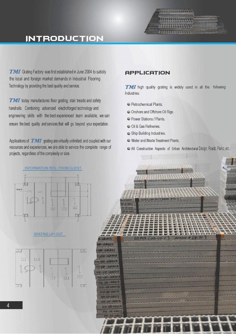
Grating Factory was first established in June 2004 to satisfy the local and foreign market demands in Industrial Flooring Technology by providing the best quality and service.
TMI today manufactures floor grating, stair treads and safety
handrails. Combining advanced electroforged technology and
engineering skills with the best experienced team available, we can
ensure the best quality and services that will go beyond your expectation.
Applications of TMJf grating are virtually unlimited; and coupled with our resources and experiences, we are able to service the complete range of projects, regardless of the complexity or size.
INFORMATION REQ. FROM CLIENT
Mari< U
GO DEI
GRATING LAY-OUT
4
A P P L I C A T I O N
TMI high quality grating is widely used in all the following Industries:
© Petrochemical Plants.
O Onshore and Offshore Oil Rigs.
O Power Stations / Plants.
© Oil & Gas Refineries.
O Ship Building Industries.
O Water and Waste Treatment Plants.
©Al l Construction Aspects of Urban Architectural Design, Roads, Parks, etc...
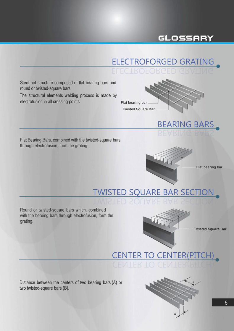
ELECTROFORGED GRATING
Steel net structure composed of flat bearing bars and round or twisted-square bars. The structural elements welding process is made by electrofusion in all Crossing points. Flat bearing bar
Twisted Square Bar
BEARING BARS
Flat Bearing Bars, combined with the twisted-square bars through electrofusion, form the grating.
Flat bearing bar
TWISTED SQUARE BAR SECTION
Round or twisted-square bars which, combined with the bearing bars through electrofusion, form the grating.
Twisted Square Bar
CENTER TO CENTER(PITCH)
Distance between the centers of two bearing bars (A) or two twisted-square bars (B).
5

MESH The center-to-center distance between the bearing bars (A) and the twisted-square bars (B).
PANEL LENGTH (x) Dimension corresponding to the maximum. Length of the bearing bar (grating bearing bar direction). This dimension is always called "length" (X), even if shorter than the width.
grating bearing bar
direction
PANEL WIDTH (Y) Dimension corresponding to the maximum length of the cross-bars. This dimension is always called "width" (Y), even if longer than the length.
FRAMING BAR
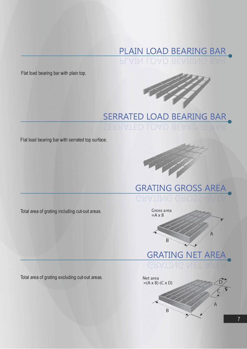
PLAIN LOAD BEARING BAf^
Flat load bearing bar with plain top.
SERRATED LOAD BEARING BAR
Flat load bearing bar with serrated top surface.
GRATING GROSS AREA
Total area of grating including cut-out areas.
GRATING NET AREA •
Total area of grating excluding cut-out areas.

FB 30 / 50 mm Pitch (Plain)

The weight of TMI Fabricated Grating will increase due to addition of banding bars, toe plates, fittings and hot dip galvanizing. Typically finished weight would bel 2% higher than the following bare metal weights before the above add-ons.
Load Table and Deflection Data 30 mm LOAD BAR PITCH
Type
Cross Road Pitch (mm)
Weight (kg/M2)
Load Bar Size (mm)
SPAN-millimeters Cross Road Pitch (mm)
Load Bar Size (mm)
150 300 450 600 750 900 1050 1200 1500 1800 2100 2400 2700 3000 3300 3600 TMI GR 20 3 100 19.05 20x3
U D
399 0.20
100 0.78
44 1.75
25 3.10
16 4.84
11 6.97
8 9.48
6 12.38
4 19.34
3 27.85
2 37.90
2 49.50
1 62.65
1 77.35
1 93.59
1 111.38
TMI GR 20 5 100 29.87 20X5
U D
665 0.20
166 0.78
74 1.75
42 3.10
27 4.84
18 6.97
14 9.48
10 12.38
7 19.34
5 27.85
3 37.90
3 49.50
2 62.65
2 77.35
1 93.59
1 111.38
TMI GR 25 3 100 23.11 25x3
U D
623 0.16
156 0.62
69 1.40
39 2.48
25 3.87
17 5.57
13 7.58
10 9.90
6 15.47
4 22.28
3 30.32
2 39.60
2 50.12
2 61.88
1 74.87
1 89.10
TMI GR 25 5 100 36.63 25x5
U D
1039 0.16
260 0.62
115 1.40
65 2.48
42 3.87
29 5.57
21 7.58
16 9.90
10 15.47
7 22.28
5 30.32
4 39.60
3 50.12
3 61.88
2 74.87
2 89.10
TMI GR 32 3 100 28.79 32x3
U D
1021 0.13
255 0.49
113 1.09
64 1.94
41 3.03
28 4.36
21 5.93
16 7.74
10 12.09
7 17.41
5 23.69
4 30.94
3 39.16
3 48.34
2 58.50
2 69.61
TMI GR 35 5 100 50.15 35x5
U D
2348 0.13
570 0.49
253 1.09
142 1.94
91 3.03
63 4.36
47 5.93
36 7.74
23 12.09
16 17.41
12 23.69
9 30.94
7 39.16
6 48.34
5 58.50
4 69.61
TMI GR 40 3 100 35.28 40x3
U D
1596 0.10
399 0.39
177 0.88
100 1.55
64 2.42
44 3.49
33 4.74
25 6.19
16 9.67
11 13.93
8 18.95
6 24.75
5 31.33
4 38.68
3 46.80
3 55.69
TMI GR 40 5
100 56.9 40X5 U D
2260 0.10
665 0.39
296 0.88
166 1.55
106 2.42
74 3.49
54 4.74
42 6.19
27 9.67
18 13.93
14 18.95
10 24.75
8 31.33
7 38.68
5 46.80
5 55.69
TMI GR 45 5 100 63.68 45x5
U D
3366 0.09
842 0.35
374 0.78
210 1.38
135 2.15
94 3.10
69 4.22
53 5.50
34 8.60
23 12.38
17 16.85
13 22.00
10 27.85
8 34.38
7 41.60
6 49.50
TMI GR 50 5 100 70.44 50x5
U D
4156 0.08
1039 0.31
462 0.70
260 1.24
166 1.94
115 2.79
85 3.79
65 4.95
42 7.74
29 11.14
21 15.16
16 19.80
13 25.06
10 30.94
9 37.44
7 44.55
TMI GR 55 5 100 72.2 55x5
U D
5028 0.08
1257 0.29
559 0.64
314 1.13
201 1.76
140 2.54
103 3.45
79 4.50
50 7.04
35 10.13
26 13.79
20 18.00
16 22.79
13 28.13
10 34.04
9 40.50
TMI GR 65 5 100 90.73 65x5
U D
7023 0.06
1756 0.24
780 0.54
439 0.96
281 1.49
195 2.15
143 2.92
110 3.81
70 5.95
49 8.57
36 11.67
27 15.24
22 19.28
18 23.80
15 28.80
12 34.27
NOTE
Span in the shaded area above have a deflection of more than 5mmfor4kPa uniformly distributed load which exceeds the deflection limits for pedestrian comfort.
U= Safe superimposed uniformly distributed load in KiloNewton / meter square (kN/m2) D= Deflection in millimeters
Serrated Conversion Table Load Bar Size (mm) 25x3 25x5 32x3 35x5 40x3 40x5 45x5 50x5 55x5 65x5 Multiply U&Cby 0.791 0.797 0.832 0.836 0.868 0.872 0.882 0.887 0.903 0.922
Multiply Deflection by 1.122 1.119 1.093 1.088 1.077 1.072 1.069 1.065 1.048 1.041
9
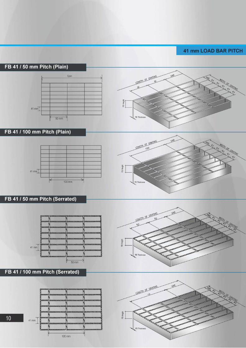
41 mm LOAD BAR PITCH
F B 41 / 50 mm Pitch (Plain)
Span s
c >
^ 50 mm ^
F B 41 / 100 mm Pitch (Plain)
F B 41 / 50 mm Pitch (Serrated)
41 mm
n J
100 mm
F B 41 / 100 mm Pitch (Serrated)
41 mm
100 mm
10
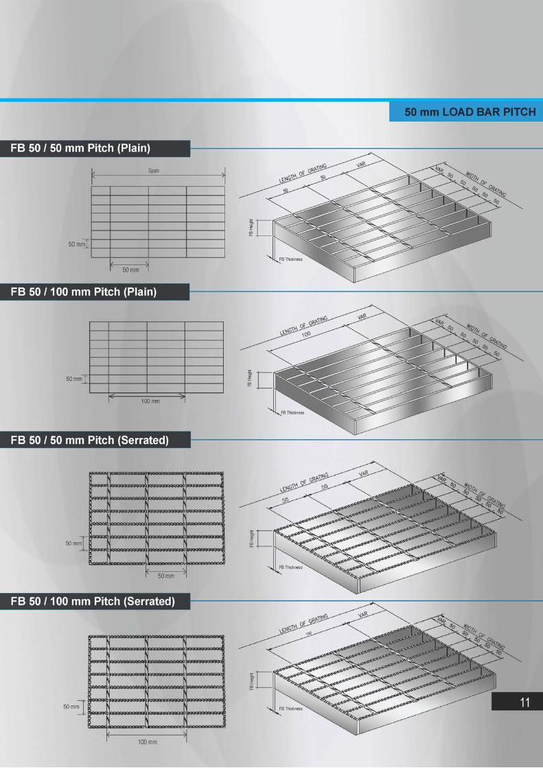
50 mm LOAD BAR PITCH
FB 50 / 50 mm Pitch (Plain)
/ Span s
( } 50 mm
F B 50 / 100 mm Pitch (Plain)
100 mm
F B 50 / 50 mm Pitch (Serrated)
100 mm
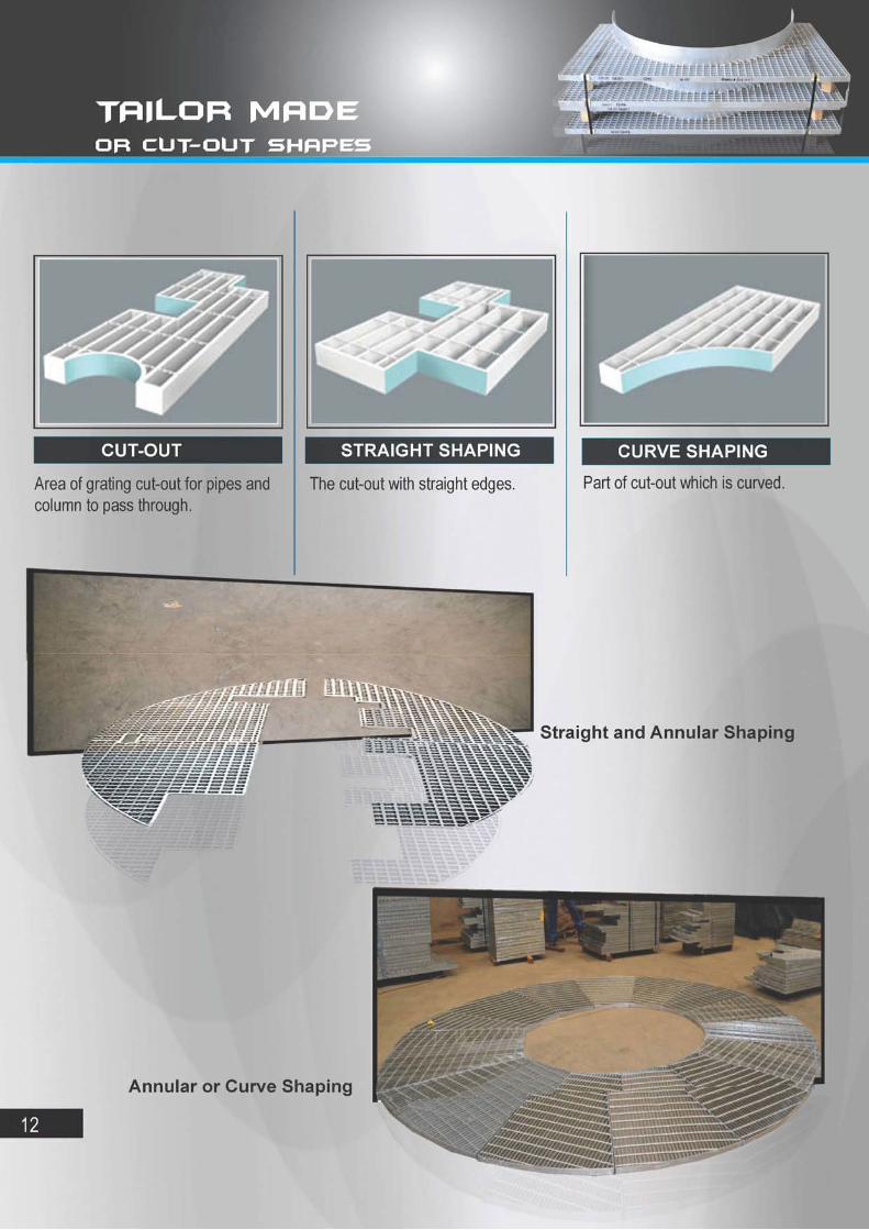
T A I L O R M A D E O R C U T - O U T S H A P E S

Stair treads can be manufactured according to the customer need with basically any combination of pitch size, bearing bar and profile. Stair tread is made of steel grating and widely used of different types of staircases, featuring easy installation, strong structure and aesthetic appearance and good water permeability. We can fabricate according to customers sizes.
BOLTED STEEL STAIR TREAD BOLTED STEEL STAIR TREAD NO NOSING WITH NOSING
WELDED STEEL STAIR TREAD WELDED STEEL STAIR TREAD

M A N U F A C T U R I N G T O L E R A N C E
ALL DIMENSIONS ARE MAXIMUM PERMISSABLE TOLERANCES
LENGTH=D +5 mm
i3mm
D1=D + 5 mm 7 ^3 m m
Fabrication Welding. Binding bars and attachments are welded with minimum 3 mm fillet weld to one side of :
Every 6th load bar on 30 mm load bar pitch. Every 4th load bar on 41 mm load bar pitch.
W & W1 are overall dimensions across the Load Bar at opposite ends of panel.
TRANSVERSE BOW (before fastening to supports)
CROSS ROD LOCATION AND LOAD BAR LEAN
1mm per 100 mm of width -Load Bars
1mm per 100 mm of width
LONGITUDINAL BOW
' i t 1 1
-Bearing bars-
10 mm 1 mm
CROSS ROD ALIGNMENT AND SPACING
TJ TT
^1/200 of len gth y = Load Bars
—-5 mm
1—1 • . —
— J U J
+ 5 mm C-C end Cross Rods in 1.50 m length
14

I N S T A L L A T I O N C L E A R A N C E
NOMINAL L— 10 mm
—
Actual cut out shall be to the next nearest load bar
N O M I N A L — i n — 10 mm T3 o n—||—rr c o -
LOAD BAR(typical)
T
—10 mm 10 mm
1 Min. Clearance Equal to rebate Angle thickness
T i l ' ' t
— • — 10 mm
— H .
•~15 mm
OVERALL DIMENSIONS
+i
a X X H X K X X X X X X K X X J i X X X X X X X ) X X X X !
TREAD DIMENSIONS
LENGTH + 0 mm - 3 mm
RECOMMENDED WIDTHS ( based on 5 mm load bars)
30 mm LB Pitch
41 mm LB Pitch
215 mm
205 mm
245 mm
245 mm
275 mm
285 mm
305 mm
325 mm
END FLAT LEAN
Fabrication welding. Binding bars and End plates are welded one side of every load bar with a minimum 3 mm
25 mm fillet weld. U 10 mm
15

TYPE-1 GRATING TYPE-2 GRATING
FILLET WELD FIRST TWO, LAST TWO & EVERY 180 mm
N- TYPE = 6th LOAD BAR W- TYPE = 4th LOAD BAR
( WITH CUT-OUT)
/(IN THIS CUT-OUT AREA) TACK - WELD EVERY TWISTED SQUARE BAR
FILLET WELD EVERY LOAD BAR .OPPOSITE SIDE OPPOSITE DIRECTION (IN THIS CUT-OUT AREA)
TYPE-3 GRATING TYPE-4 GRATING WITH NOTCH) ( WITH PENETRATION)
TACK - WELD EVERY TWISTED SQUARE BAR (IN THIS NOTCH AREA)
FILLET WELD EVERY LOAD BAR 'OPPOSITE SIDE OPPOSITE DIRECTION
(IN THIS CUT-OUT AREA)
WIDTH
TACK - WELD EVERY TWISTED SQUARE BAR ^( IN THIS PENETRATION AREA)
FILLET WELD EVERY LOAD BAR OPPOSITE SIDE OPPOSITE DIRECTION
WIDTH
16
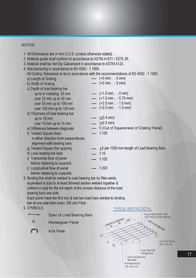
NOTES:
1. All Dimensions are in mm U.O.S. (unless otherwise stated). 2. Material grade shall conform in accordance to ASTM A1011 / S275 JR. 3. Material shall be Hot Dip Galvanized in accordance to ASTM A123. 4. Manufacturing in accordance to BS 4592 - 1 1995.
All Grating Tolerances to be in accordance with the recommendations of BS 4592 - 1 1995. (+0 mm , - 5 mm) (+0 mm , - 5 mm)
(+1.0 mm , (+1.5 mm , (+2.0 mm , (+2.0 mm ,
5 mm) 0.75 mm) 1.0 mm) 1.5 mm)
a) Length of Grating b) Width of Grating c) Depth of load bearing bar
up to & including 25 mm over 25 mm up to 50 mm over 50 mm up to 100 mm over 100 mm up to 150 mm
d) Thickness of load bearing bar up to 10 mm over 10 mm up to 15 mm
e) Difference between diagonals f) Twisted Square Bars
in either direction from perpendicular alignment with bearing bars.
g) Twisted Square Bar spacing. h) Load bearing bar lean i) Transverse Bow of panel
before fastening to supports. j) Longitudinal Bow of panel -
before fastening to supports. 5. Binding Bar shall be welded to load bearing bar by fillet welds,
equivalent in size to at least thinnest section welded together & uniform in size for the full depth of the contact distance of the load bearing bars one side. Each panel have the first two & last two load bars welded to binding bar at one side then every 180 mm Pitch.
6. SYMBOLS: TYPICAL GRATING DETAIL
(+0.4 mm) (+0.5 mm) 5 (Out of Squareness of Grating Panel) 1:100
+5 per 1500 mm length of Load Bearing Bars 1:10 1:100
1:200
R
Span of Load Bearing Bars
Rectangular Panel
Kick Plate
FILLET WELD FIRST TWO LAST TWO & EVERY 180 mm
35 , ' "V"
6 mm TWISTED BAR @ 50 c/c
AUTO PROJECTION WELDING
FLAT BAR PLATE ( FB - 35 X 5 S)
FLAT END PLATE (FB - 35 X 5 S)
5
17

H E A V Y D U T Y GRATING
Heavy Duty products are designed to meet the customer need for grating subject to heavy rolling and static loads such as:
• Highways
• Plant Floors
• Loading Docks
• Inlet Covers
• Airports
It is also commonly subjected to shock and impact loads.
Heavy Duty Grating are manufactured in a wide variety of bar sizes and spacings.
ADVANTAGE of Heavy Duty - Serrated
Maximize the Skid Resistance. Enhance the anti-slip quality on the surface of the grating.
Provide greater pedestrian safety.
18

I N S T A L L A T I O N C L I P S & F A S T E N E R S
T
/ £ —
3 K / 1 N ' 20 i
i mm
Field-welding Support member
Field Installation and Fixing Sketch
10
O
O
Bearing bars
O
O
Installation Fastener
Diagram for Fastener Installation
i V 1 1
1. There are two ways of installation for grating. One way is by welding and the other is by fasteners. The method of installation by fasteners has a properties of easy to assemble and disassemble, thus preventing of destroying the zinc layer.
2. Installation fastener is suitable for all types of grating. It is made of up-fasteners, down-fasteners and inside turret cylinder bolt M10.
3. Welding method is an angle welding at the first bearing bar of every corner on the grating. A welding seam of which is not less than 20 mm length and less than 3 mm height.
4 . At least every one square meter requires four lots of installation fasteners on grating to fix. Install more fasteners on the supportable construction when the span is larger.
5. We can supply stainless installation fasteners to satisfy our customer.
6. Please indicate clearly the type, quantity and material when you purchase installation fasteners.

A D D I T I O N A L P R O D U C T S
Cover Grates are widely used for municipal roads, garden facilities, residential quarters, schools, stadium management and other different places. The company can also do according to special customer requirements, design and manufacture other specifications to cover the shape of the groove. In accordance to the use of different locations, the company can provide different materials ditch (well) cover.
Cover Grates size selection description: 1. Bearing support direction, the ditch (well) wide gap will remain flat length of the L. 2. The standard width 995 mm, leaving space between plates 5 mm. 3. Size of diameter for the Lifting hook based on customer design. 4. Anchors designed to fit over two bearing bars and a minimum of four anchors provided for each panel. 5. Other special sizes quoted on request to meet your requirements.
Angle Bar
Anchor Rod
COVER GRATES
Bearing Support Lifting Hook
20

Plank Grating is a one-piece construction product that allows easy field handling and cutting. The construction is formed and punched sheet metal. The formed metal planks are available in galvanized and plain steel.
PLANK GRATING
Large Hole Surface
Plank choices include grating with surface openings that are mesh and different sizes of hole along with solid surfaces.
Most plank grating are lightweight and offer significantly higher slip resistance surfaces than bar grating styles.
Medium Hole Surface
21

www.tmi-co.com
ORDERING I N F O R M A T I O N In order for us to serve you better, you need to provide the type and area of grating needed, and also the dimension and quantity along with the necessary flat drawing when you need a large area of grating:
• Dimension of total area of grating. • Support structure (including section dimension, location of supporting beam and open direction of
channel steel). • Location and dimension needed to cut out and of moving steel grating. • Location and dimension of nosing, end plate and specified profile connection.
Indicate the type and quantity of installation fastener, at least four lots of fasteners needed for each panel in principle.
Indicate the type, pieces and dimension of stairtread, surface treatment and whether to change angle for side.
Area of grating is accounted by gross area, which is accounted by maximum outside dimension, including cut out and gap.
Only if all above items are clarified, you will get the exact offer.


