26
TELECOM Training Lab TELECOM
TELECOM Training Lab
TE
LEC
OM
About SES
An Edtech industry leader and innovator, SES Scientific Educational Systems, goes above and beyond to supply educators and learners with the best educational systems, including Neulog, Degem Systems, MultiCenter and MagiClass. Renowned for their ability to cater to numerous fields, sectors and segments, SES systems spread across a wide spectrum, offering unique solutions in the fields of electronics, microcontrollers, telecommunication, autotronics, mechatronics, pneumatics, hydraulics, CNC machines, refrigeration and air-conditioning, green energy, computerized systems, science, robotics, logger sensors and STEM. Each proprietary SES system and device is perfectly designed and manufactured from the highest quality materials in accordance with all safety requirements and regulations. SES is a quality assured firm with the certification of ISO-9001:2015. SES solutions are used in over 50 countries worldwide by professional developers for high-level technological commercial products and both governmental and private institutions covering educational programs for universities, colleges, vocational training centers and schools, high schools, junior high schools and primary schools.
1 Telecom V4_5
MDC-3210 – MODCOM Modern Communication Training Systems
The MDC-3210 Modern Communication product line is designed to provide practical training for engineers and technologists in the fundamentals of analog and digital communications that are the basis of modern communications and telecommunication systems. The prime objective is to study the principles of operation of various communications techniques and their effect on real life signals such as speech, music and data. The training system consists of two service units, a base unit and six different modules: MDC-3201 – Audio data acquisition service unit MDC-3202 – RF service unit MDC-3203 – Base unit and power supply MDC-3211 – Audio and data signals MDC-3212 – Source encoding and decoding MDC-3213 – Baseband transmission and synchronization MDC-3214 – Linear modulation and demodulation MDC-3215 – Angle modulation and demodulation MDC-3216 – Superheterodyne receiver The above two service units (MDC-3201 and MDC-3202) and six modules that plug into the four available slots in the MDC-3203 base unit enable to quickly configure the system for each experiment. The service units provide virtual instruments for generating and analyzing signals. Courseware: The accompanying courseware for each experiment runs in the MS-WINDOWS environment, offers essential theory, easy to follow step-by-step experiment procedure instructions and verifies answers to multiple-choice questions. The student courseware and instructor guide are written by pedagogical experts in modern communications technology to support every stage of the learning process.
2 Telecom V4_5
MDC-3203 – Base Unit This unit contains four empty slots or racks to house the various communication modules and service units, an external power supply and a set of patch cords for connecting the various access jacks on each module panel. Each student workstation requires a personal computer with MS Windows. MDC-3201 – Audio Data Acquisition Service Unit
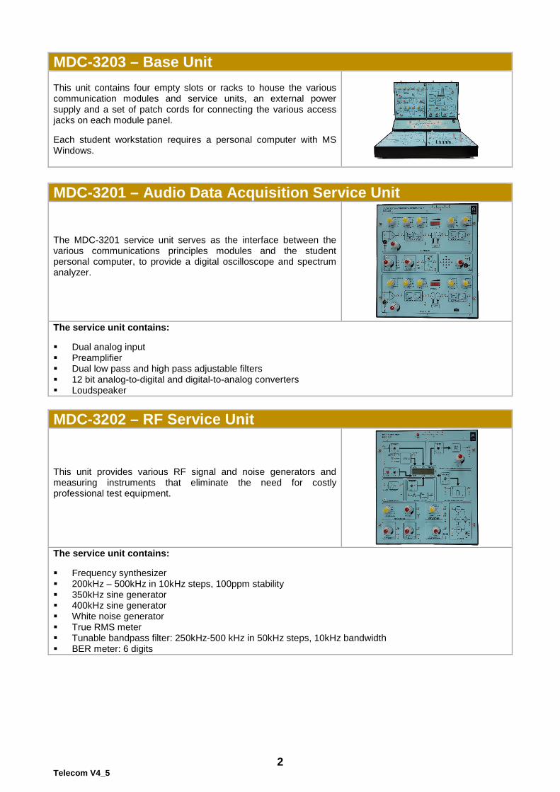
The MDC-3201 service unit serves as the interface between the various communications principles modules and the student personal computer, to provide a digital oscilloscope and spectrum analyzer.
The service unit contains: Dual analog input Preamplifier Dual low pass and high pass adjustable filters 12 bit analog-to-digital and digital-to-analog converters Loudspeaker MDC-3202 – RF Service Unit
This unit provides various RF signal and noise generators and measuring instruments that eliminate the need for costly professional test equipment.
The service unit contains: Frequency synthesizer 200kHz – 500kHz in 10kHz steps, 100ppm stability 350kHz sine generator 400kHz sine generator White noise generator True RMS meter Tunable bandpass filter: 250kHz-500 kHz in 50kHz steps, 10kHz bandwidth BER meter: 6 digits
3 Telecom V4_5
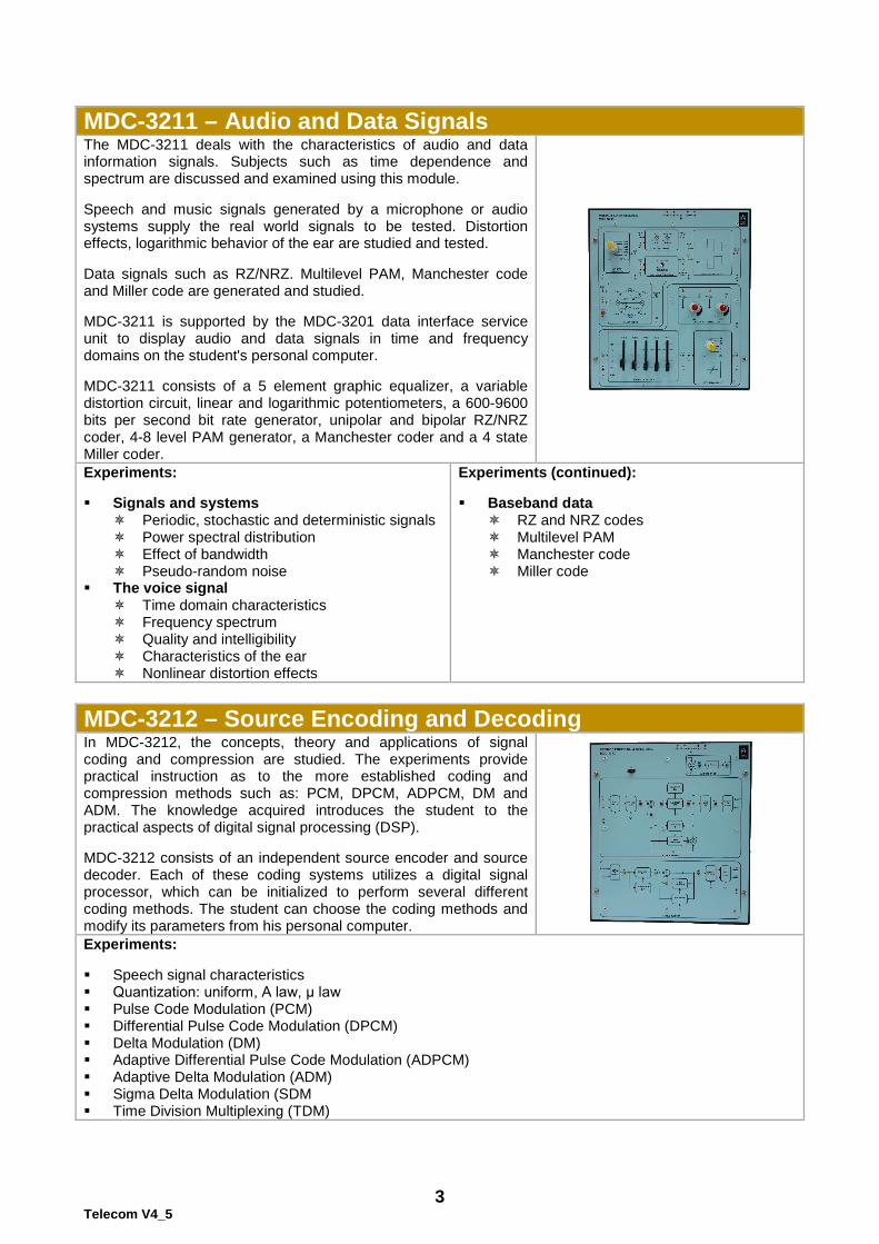
MDC-3211 – Audio and Data Signals The MDC-3211 deals with the characteristics of audio and data information signals. Subjects such as time dependence and spectrum are discussed and examined using this module. Speech and music signals generated by a microphone or audio systems supply the real world signals to be tested. Distortion effects, logarithmic behavior of the ear are studied and tested. Data signals such as RZ/NRZ. Multilevel PAM, Manchester code and Miller code are generated and studied. MDC-3211 is supported by the MDC-3201 data interface service unit to display audio and data signals in time and frequency domains on the student's personal computer. MDC-3211 consists of a 5 element graphic equalizer, a variable distortion circuit, linear and logarithmic potentiometers, a 600-9600 bits per second bit rate generator, unipolar and bipolar RZ/NRZ coder, 4-8 level PAM generator, a Manchester coder and a 4 state Miller coder.
Experiments: Signals and systems
Periodic, stochastic and deterministic signals Power spectral distribution Effect of bandwidth Pseudo-random noise
The voice signal Time domain characteristics Frequency spectrum Quality and intelligibility Characteristics of the ear Nonlinear distortion effects
Experiments (continued): Baseband data
RZ and NRZ codes Multilevel PAM Manchester code Miller code
MDC-3212 – Source Encoding and Decoding In MDC-3212, the concepts, theory and applications of signal coding and compression are studied. The experiments provide practical instruction as to the more established coding and compression methods such as: PCM, DPCM, ADPCM, DM and ADM. The knowledge acquired introduces the student to the practical aspects of digital signal processing (DSP). MDC-3212 consists of an independent source encoder and source decoder. Each of these coding systems utilizes a digital signal processor, which can be initialized to perform several different coding methods. The student can choose the coding methods and modify its parameters from his personal computer. Experiments: Speech signal characteristics Quantization: uniform, A law, μ law Pulse Code Modulation (PCM) Differential Pulse Code Modulation (DPCM) Delta Modulation (DM) Adaptive Differential Pulse Code Modulation (ADPCM) Adaptive Delta Modulation (ADM) Sigma Delta Modulation (SDM Time Division Multiplexing (TDM)

4 Telecom V4_5
MDC-3213 – Baseband Transmission & Synchronization In MDC-3213, various techniques of baseband data transmission currently used in digital communications systems are studied. Data signals are converted into baseband sequence of data symbols. Specifically, 2B1Q and AMI/TBC coders are studied. The module also contains a transmission channel, a receiver and two different time recovery synchronization circuits. The Baseband Transmission and Synchronization module MDC-3213 provides a number of communication functions that enable the student to perform meaningful and interesting experiments. Experiments: Twined binary code
Spectral shaping by TBC precoding AMI code
Error propagation Differential coding
Comparison of AMI with 4-level PAM (2B1Q) Sensitivity to DC/AC coupling Line polarity sensitivity Bandwidth Synchronization
Experiments (continued): Intersymbol interference (ISI) & eye pattern
Eye patterns for various bandwidths with AMI and 2B1Q codes
Time recovery with squaring circuit Time recovery with zero crossing circuit AMI noise performance 2B1Q noise performance Timing recovery performance
MDC-3214 – Linear Modulation and Demodulation In MDC-3214, some of the linear modulation techniques currently used in modern analog and digital communications systems are studied. An analog or digital information signal is conveyed on to a carrier signal whose instantaneous amplitude varies according to the variation of the original information signal. Specifically, Double-Sideband modulation DSB), conventional Amplitude Modulation (AM), Single-Sideband Modulation (SSB) and Quadrature Amplitude modulation (QAM) will be studied. The Linear Modulation and Demodulation module MDC-3214 provides a number of communication functions that enable the student to perform meaningful and interesting experiments.
Experiments: Frequency translation
Demonstration of frequency translation and spectrum Frequency division multiplexing (FDM)
Double Sideband Suppressed Carrier (DSB-SC) Modulation. Amplitude Modulation. Single Side Band (SSB) Modulation. Quadrature Amplitude Modulation (QAM). Synchronous Demodulation Correlation Receiver Envelope Detector
5 Telecom V4_5
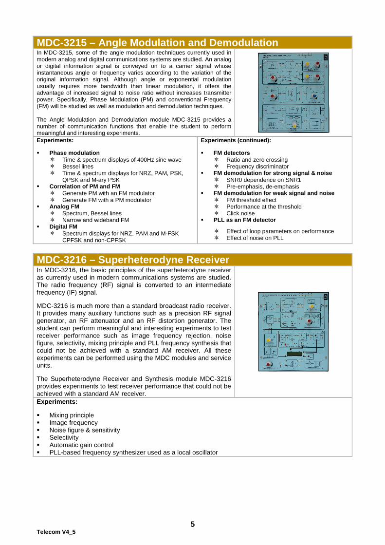
MDC-3215 – Angle Modulation and Demodulation In MDC-3215, some of the angle modulation techniques currently used in modern analog and digital communications systems are studied. An analog or digital information signal is conveyed on to a carrier signal whose instantaneous angle or frequency varies according to the variation of the original information signal. Although angle or exponential modulation usually requires more bandwidth than linear modulation, it offers the advantage of increased signal to noise ratio without increases transmitter power. Specifically, Phase Modulation (PM) and conventional Frequency (FM) will be studied as well as modulation and demodulation techniques. The Angle Modulation and Demodulation module MDC-3215 provides a number of communication functions that enable the student to perform meaningful and interesting experiments. Experiments: Phase modulation
Time & spectrum displays of 400Hz sine wave Bessel lines Time & spectrum displays for NRZ, PAM, PSK,
QPSK and M-ary PSK Correlation of PM and FM
Generate PM with an FM modulator Generate FM with a PM modulator
Analog FM Spectrum, Bessel lines Narrow and wideband FM
Digital FM Spectrum displays for NRZ, PAM and M-FSK
CPFSK and non-CPFSK
Experiments (continued): FM detectors
Ratio and zero crossing Frequency discriminator
FM demodulation for strong signal & noise SNR0 dependence on SNR1 Pre-emphasis, de-emphasis
FM demodulation for weak signal and noise FM threshold effect Performance at the threshold Click noise
PLL as an FM detector
Effect of loop parameters on performance Effect of noise on PLL
MDC-3216 – Superheterodyne Receiver In MDC-3216, the basic principles of the superheterodyne receiver as currently used in modern communications systems are studied. The radio frequency (RF) signal is converted to an intermediate frequency (IF) signal. MDC-3216 is much more than a standard broadcast radio receiver. It provides many auxiliary functions such as a precision RF signal generator, an RF attenuator and an RF distortion generator. The student can perform meaningful and interesting experiments to test receiver performance such as image frequency rejection, noise figure, selectivity, mixing principle and PLL frequency synthesis that could not be achieved with a standard AM receiver. All these experiments can be performed using the MDC modules and service units. The Superheterodyne Receiver and Synthesis module MDC-3216 provides experiments to test receiver performance that could not be achieved with a standard AM receiver.
Experiments: Mixing principle Image frequency Noise figure & sensitivity Selectivity Automatic gain control PLL-based frequency synthesizer used as a local oscillator

6 Telecom V4_5
MDC-3241 – Antenna Training System MDC-3241 Antenna Training System is an ideal training equipment to teach the important fundamentals of antennas as applied to modern communication systems. The MDC-3241 Antenna Training System has been specially designed for engineering colleges and technical training centers. It is very useful for practical verification of antenna operating characteristics by students. All of the necessary measuring equipment and accessories are provided in the training system. The student manual provides theoretical concepts and detailed experiment procedures for each type of antenna. The training system includes a set of modular mechanical elements forming various antennas, a transmitter unit and a detector unit. All the accessories are packed in a convenient carrying case. The training system includes fully documented student workbook and operating manual.
Technical characteristics: RF generator (750MHz approx., adjustable output
level) Tone generator (1KHz approx., adjustable output
level) Directional coupler (forward & reverse selectable) Matching stub (slider type) Antenna rotation (0-360o resolution 1 degree) Receiving antenna (folded dipole with reflector) Detector display (adjustable level meter) Power supply (220V ±10%, 50Hz, 3VA approx.) Interconnections (4mm banana sockets) Dimensions – W 520 × H 120 × D 300 (main unit) Weight – 2.8Kg (main unit) Experiments: Polar plots & polarization Wave modulation & demodulation Antenna gain, antenna beam width study Element current, front-back ratio study Antenna matching Antenna radiation with distance SWR measurement Measure antenna element current Supplied accessories: Transmitting Antennas
Dipole l/2 Dipole l/4 Yagi UDA folded dipole (3 E) Yagi UDA folded dipole (5 E) Yagi UDA dipole (7 E) Yagi UDA dipole (5 E)
Supplied accessories (continued):
Horizontal end fed hertz antenna Horizontal end fed zeppelin antenna Ground plane antenna Ground plane with reflector & director Slot antenna l/2 Loop antenna Helix antenna l/2 phase array l/4 phase array Combined collinear array Log periodic antenna Rhombus antenna Cut parabolic reflector antenna 3l/2 dipole antenna Broadside array Folded dipole receiving antenna
Current probe Mounting stands BNC-tee BNC-BNC adapter M BNC-BNC adapter F BNC-BNC cable Screwdriver Radiation pattern plotting software Polar graph paper Antenna fabrication kit Power cord Accessories case Required accessories: Personal computer with MS-Windows
7 Telecom V4_5
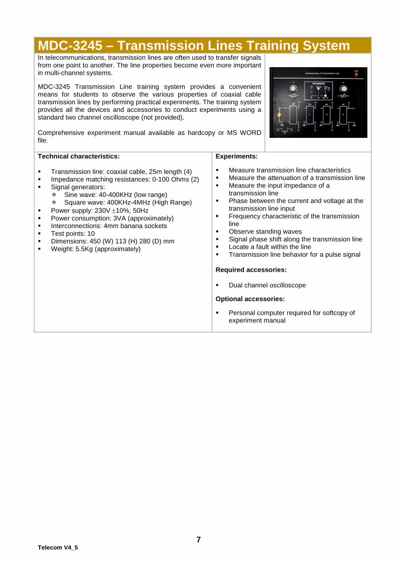
MDC-3245 – Transmission Lines Training System In telecommunications, transmission lines are often used to transfer signals from one point to another. The line properties become even more important in multi-channel systems. MDC-3245 Transmission Line training system provides a convenient means for students to observe the various properties of coaxial cable transmission lines by performing practical experiments. The training system provides all the devices and accessories to conduct experiments using a standard two channel oscilloscope (not provided). Comprehensive experiment manual available as hardcopy or MS WORD file.
Technical characteristics: Transmission line: coaxial cable, 25m length (4) Impedance matching resistances: 0-100 Ohms (2) Signal generators:
Sine wave: 40-400KHz (low range) Square wave: 400KHz-4MHz (High Range)
Power supply: 230V ±10%, 50Hz Power consumption: 3VA (approximately) Interconnections: 4mm banana sockets Test points: 10 Dimensions: 450 (W) 113 (H) 280 (D) mm Weight: 5.5Kg (approximately)
Experiments: Measure transmission line characteristics Measure the attenuation of a transmission line Measure the input impedance of a
transmission line Phase between the current and voltage at the
transmission line input Frequency characteristic of the transmission
line Observe standing waves Signal phase shift along the transmission line Locate a fault within the line Transmission line behavior for a pulse signal Required accessories: Dual channel oscilloscope Optional accessories: Personal computer required for softcopy of
experiment manual
8 Telecom V4_5
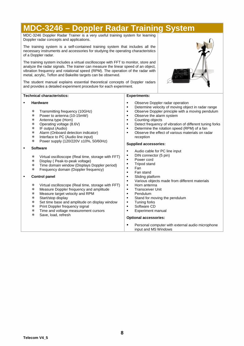
MDC-3246 – Doppler Radar Training System MDC-3246 Doppler Radar Trainer is a very useful training system for learning Doppler radar concepts and applications. The training system is a self-contained training system that includes all the necessary instruments and accessories for studying the operating characteristics of a Doppler radar. The training system includes a virtual oscilloscope with FFT to monitor, store and analyze the radar signals. The trainer can measure the linear speed of an object, vibration frequency and rotational speed (RPM). The operation of the radar with metal, acrylic, Teflon and Bakelite targets can be observed. The student manual explains essential theoretical concepts of Doppler radars and provides a detailed experiment procedure for each experiment.
Technical characteristics: Hardware
Transmitting frequency (10GHz) Power to antenna (10-15mW) Antenna type (Horn) Operating voltage (8.6V) IF output (Audio) Alarm (Onboard detection indicator) Interface to PC (Audio line input) Power supply (120/220V ±10%, 50/60Hz)
Software
Virtual oscilloscope (Real time, storage with FFT) Display ( Peak-to-peak voltage) Time domain window (Displays Doppler period) Frequency domain (Doppler frequency)
Control panel
Virtual oscilloscope (Real time, storage with FFT) Measure Doppler frequency and amplitude Measure target velocity and RPM Start/stop display Set time base and amplitude on display window Print Doppler frequency signal Time and voltage measurement cursors Save, load, refresh
Experiments: Observe Doppler radar operation Determine velocity of moving object in radar range Observe Doppler principle with a moving pendulum Observe the alarm system Counting objects Detect frequency of vibration of different tuning forks Determine the rotation speed (RPM) of a fan Observe the effect of various materials on radar
reception Supplied accessories: Audio cable for PC line input DIN connector (5 pin) Power cord Tripod stand Fan Fan stand Sliding platform Various objects made from different materials Horn antenna Transceiver Unit Pendulum Stand for moving the pendulum Tuning forks Software CD Experiment manual Optional accessories: Personal computer with external audio microphone
input and MS Windows
9 Telecom V4_5
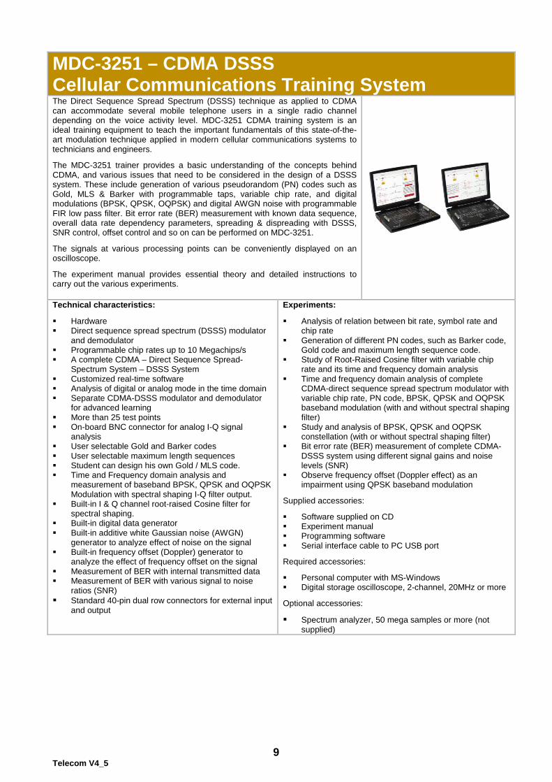
MDC-3251 – CDMA DSSS Cellular Communications Training System The Direct Sequence Spread Spectrum (DSSS) technique as applied to CDMA can accommodate several mobile telephone users in a single radio channel depending on the voice activity level. MDC-3251 CDMA training system is an ideal training equipment to teach the important fundamentals of this state-of-the-art modulation technique applied in modern cellular communications systems to technicians and engineers. The MDC-3251 trainer provides a basic understanding of the concepts behind CDMA, and various issues that need to be considered in the design of a DSSS system. These include generation of various pseudorandom (PN) codes such as Gold, MLS & Barker with programmable taps, variable chip rate, and digital modulations (BPSK, QPSK, OQPSK) and digital AWGN noise with programmable FIR low pass filter. Bit error rate (BER) measurement with known data sequence, overall data rate dependency parameters, spreading & dispreading with DSSS, SNR control, offset control and so on can be performed on MDC-3251. The signals at various processing points can be conveniently displayed on an oscilloscope. The experiment manual provides essential theory and detailed instructions to carry out the various experiments.
Technical characteristics: Hardware Direct sequence spread spectrum (DSSS) modulator
and demodulator Programmable chip rates up to 10 Megachips/s A complete CDMA – Direct Sequence Spread-
Spectrum System – DSSS System Customized real-time software Analysis of digital or analog mode in the time domain Separate CDMA-DSSS modulator and demodulator
for advanced learning More than 25 test points On-board BNC connector for analog I-Q signal
analysis User selectable Gold and Barker codes User selectable maximum length sequences Student can design his own Gold / MLS code. Time and Frequency domain analysis and
measurement of baseband BPSK, QPSK and OQPSK Modulation with spectral shaping I-Q filter output.
Built-in I & Q channel root-raised Cosine filter for spectral shaping.
Built-in digital data generator Built-in additive white Gaussian noise (AWGN)
generator to analyze effect of noise on the signal Built-in frequency offset (Doppler) generator to
analyze the effect of frequency offset on the signal Measurement of BER with internal transmitted data Measurement of BER with various signal to noise
ratios (SNR) Standard 40-pin dual row connectors for external input
and output
Experiments: Analysis of relation between bit rate, symbol rate and
chip rate Generation of different PN codes, such as Barker code,
Gold code and maximum length sequence code. Study of Root-Raised Cosine filter with variable chip
rate and its time and frequency domain analysis Time and frequency domain analysis of complete
CDMA-direct sequence spread spectrum modulator with variable chip rate, PN code, BPSK, QPSK and OQPSK baseband modulation (with and without spectral shaping filter)
Study and analysis of BPSK, QPSK and OQPSK constellation (with or without spectral shaping filter)
Bit error rate (BER) measurement of complete CDMA-DSSS system using different signal gains and noise levels (SNR)
Observe frequency offset (Doppler effect) as an impairment using QPSK baseband modulation
Supplied accessories: Software supplied on CD Experiment manual Programming software Serial interface cable to PC USB port Required accessories: Personal computer with MS-Windows Digital storage oscilloscope, 2-channel, 20MHz or more Optional accessories:
Spectrum analyzer, 50 mega samples or more (not supplied)
10 Telecom V4_5
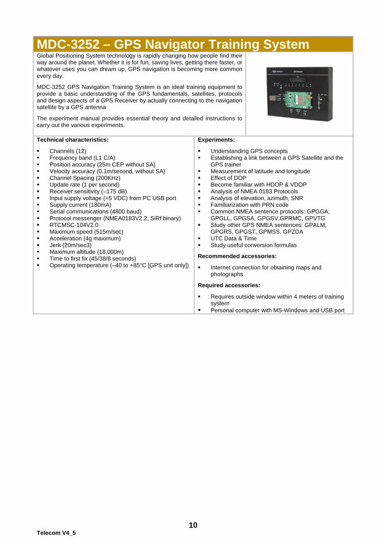
MDC-3252 – GPS Navigator Training System Global Positioning System technology is rapidly changing how people find their way around the planet. Whether it is for fun, saving lives, getting there faster, or whatever uses you can dream up, GPS navigation is becoming more common every day. MDC-3252 GPS Navigation Training System is an ideal training equipment to provide a basic understanding of the GPS fundamentals, satellites, protocols and design aspects of a GPS Receiver by actually connecting to the navigation satellite by a GPS antenna The experiment manual provides essential theory and detailed instructions to carry out the various experiments.
Technical characteristics: Channels (12) Frequency band (L1 C/A) Position accuracy (25m CEP without SA) Velocity accuracy (0.1m/second, without SA) Channel Spacing (200KHz) Update rate (1 per second) Receiver sensitivity (–175 dB) Input supply voltage (+5 VDC) from PC USB port Supply current (180mA) Serial communications (4800 baud) Protocol messenger (NMEA0183V2.2, SiRf binary) RTCMSC-104V2.0 Maximum speed (515m/sec) Acceleration (4g maximum) Jerk (20m/sec3) Maximum altitude (18,000m) Time to first fix (45/38/8 seconds) Operating temperature (–40 to +85°C [GPS unit only])
Experiments: Understanding GPS concepts Establishing a link between a GPS Satellite and the
GPS trainer Measurement of latitude and longitude Effect of DOP Become familiar with HDOP & VDOP Analysis of NMEA 0183 Protocols Analysis of elevation, azimuth, SNR Familiarization with PRN code Common NMEA sentence protocols: GPGGA,
GPGLL, GPGSA, GPGSV,GPRMC, GPVTG Study other GPS NMEA sentences: GPALM,
GPGRS, GPGST, GPMSS, GPZDA UTC Data & Time Study useful conversion formulas Recommended accessories: Internet connection for obtaining maps and
photographs Required accessories: Requires outside window within 4 meters of training
system Personal computer with MS-Windows and USB port
11 Telecom V4_5
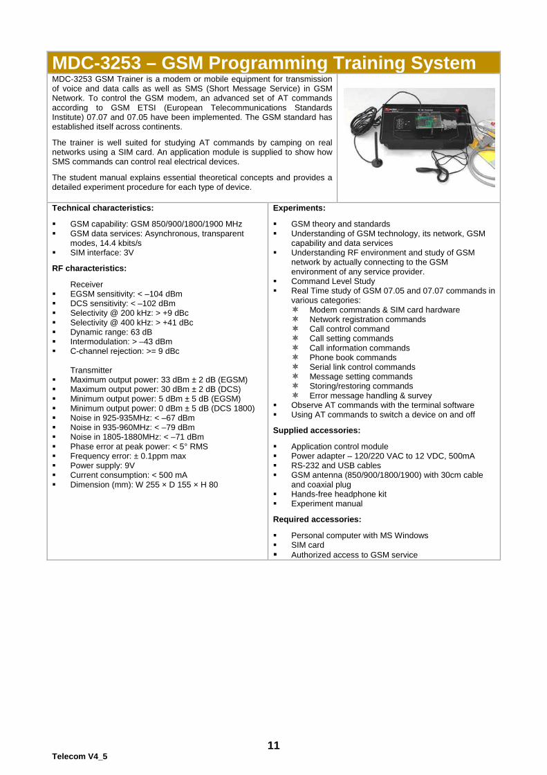
MDC-3253 – GSM Programming Training System MDC-3253 GSM Trainer is a modem or mobile equipment for transmission of voice and data calls as well as SMS (Short Message Service) in GSM Network. To control the GSM modem, an advanced set of AT commands according to GSM ETSI (European Telecommunications Standards Institute) 07.07 and 07.05 have been implemented. The GSM standard has established itself across continents. The trainer is well suited for studying AT commands by camping on real networks using a SIM card. An application module is supplied to show how SMS commands can control real electrical devices. The student manual explains essential theoretical concepts and provides a detailed experiment procedure for each type of device.
Technical characteristics: GSM capability: GSM 850/900/1800/1900 MHz GSM data services: Asynchronous, transparent
modes, 14.4 kbits/s SIM interface: 3V RF characteristics:
Receiver EGSM sensitivity: < –104 dBm DCS sensitivity: < –102 dBm Selectivity @ 200 kHz: > +9 dBc Selectivity @ 400 kHz: > +41 dBc Dynamic range: 63 dB Intermodulation: > –43 dBm C-channel rejection: >= 9 dBc
Transmitter
Maximum output power: 33 dBm ± 2 dB (EGSM) Maximum output power: 30 dBm ± 2 dB (DCS) Minimum output power: 5 dBm ± 5 dB (EGSM) Minimum output power: 0 dBm ± 5 dB (DCS 1800) Noise in 925-935MHz: < –67 dBm Noise in 935-960MHz: < –79 dBm Noise in 1805-1880MHz: < –71 dBm Phase error at peak power: < 5° RMS Frequency error: ± 0.1ppm max Power supply: 9V Current consumption: < 500 mA Dimension (mm): W 255 × D 155 × H 80
Experiments: GSM theory and standards Understanding of GSM technology, its network, GSM
capability and data services Understanding RF environment and study of GSM
network by actually connecting to the GSM environment of any service provider.
Command Level Study Real Time study of GSM 07.05 and 07.07 commands in
various categories: Modem commands & SIM card hardware Network registration commands Call control command Call setting commands Call information commands Phone book commands Serial link control commands Message setting commands Storing/restoring commands Error message handling & survey
Observe AT commands with the terminal software Using AT commands to switch a device on and off Supplied accessories: Application control module Power adapter – 120/220 VAC to 12 VDC, 500mA RS-232 and USB cables GSM antenna (850/900/1800/1900) with 30cm cable
and coaxial plug Hands-free headphone kit Experiment manual Required accessories: Personal computer with MS Windows SIM card Authorized access to GSM service
12 Telecom V4_5
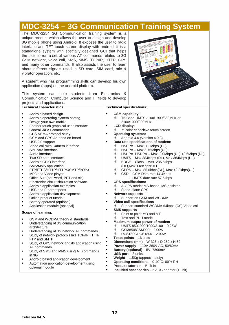
MDC-3254 – 3G Communication Training System The MDC-3254 3G Communication training system is a unique product which allows the user to design and develop 3G mobile phone using Android. It exposes the user to radio interface and TFT touch screen display with android. It is a standalone system with specially designed GUI that helps the user to run a set of various AT commands related to 3G GSM network, voice call, SMS, MMS, TCP/IP, HTTP, GPS and many other commands. It also assists the user to learn about different signals used in SD card, SIM card, mic & vibrator operation, etc. A student who has programming skills can develop his own application (apps) on the android platform. This system can help students from Electronics & Communication, Computer Science and IT fields to develop projects and applications. Technical characteristics: Android based design Android operating system porting Design your own mobile Feather touch graphical user interface Control via AT commands GPS NEMA protocol study GSM and GPS Antenna on board USB 2.0 support Video call with Camera interface SIM card interface Audio interface Two SD card interface Android GPIO interface SMS/MMS application FTP/FTPS/HTTP/HTTPS/SMTP/POP3 MP3 and Video player Office Suit (pdf, word, PPT and xls) Electronics circuit simulation software Android application examples USB and Ethernet ports Android application development Online product tutorial Battery operated (optional) Application module (optional) Scope of learning: GSM and WCDMA theory & standards Understanding of 3G communication
architecture Understanding of 3G network AT commands Study of network protocols like TCP/IP, HTTP,
FTP and SMTP Study of GPS network and its application using
AT commands Study of SMS and MMS using AT commands
in 3G Android based application development Automation application development using
optional module
Technical specifications: GSM capability:
Tri-Band UMTS 2100/1900/850MHz or 2100/1900/900MHz
LCD display: 7" color capacitive touch screen
Operating systems: Android 4.0 (Version 4.0.3)
Data rate specifications of modem: HSDPA – Max. 7.2Mbps (DL) HSUPA – Max.5.76Mbps (UL) HSUPA+HSDPA – Max. 2.0Mbps (UL) +3.6Mbps (DL) UMTS – Max.384Kbps (DL), Max.384Kbps (UL) EDGE – Class – Max. 236.8kbps
(DL),Max.118Kbps(UL) GPRS – Max. 85.6kbps(DL), Max.42.8kbps(UL) CSD – GSM Data rate 14.4Kbps
– UMTS date rate 57.6kbps GPS specifications:
A-GPS mode: MS-based, MS-assisted Stand-alone GPS
Network supports Support on GSM and WCDMA
Video call specifications Support standard WCDMA 64kbps (CS) Video call
SMS supports Point to point MO and MT Text and PDU mode
Maximum output power of modem UMTS 8501900/1900/2100 – 0.25W GSM850/GSM900 – 2.00W DCS1800/PCS1800 – 2.00W
Tests points – 16 units Dimensions (mm) – W 326 x D 252 x H 52 Power supply – 110V-260V AC, 50/60Hz Battery (optional) – 5V, 7800mA USB port – 3 units Weight – 1.5Kg (approximately) Operating conditions – 0-40°C; 80% RH Product tutorials – Built-in Included accessories – 5V DC adaptor (1 unit)
13 Telecom V4_5
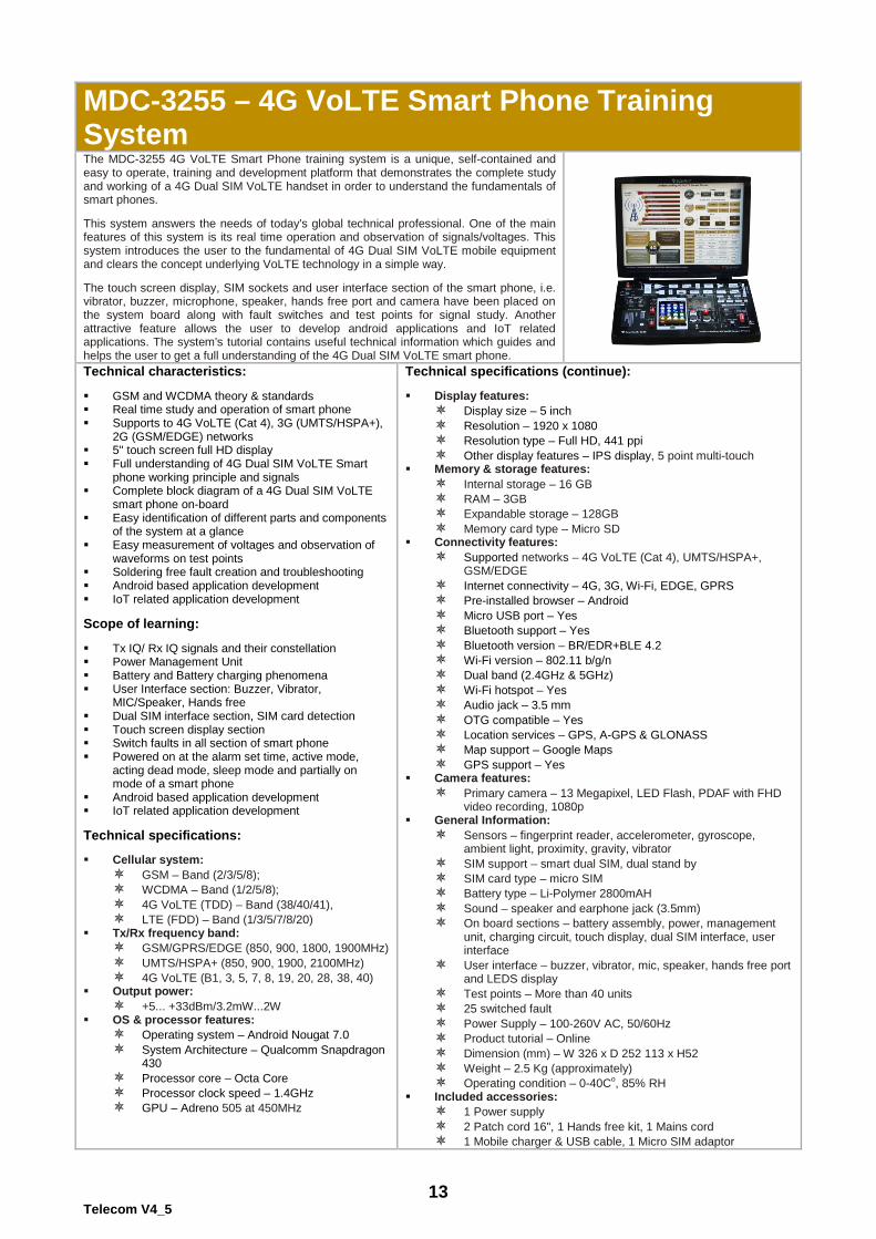
MDC-3255 – 4G VoLTE Smart Phone Training System The MDC-3255 4G VoLTE Smart Phone training system is a unique, self-contained and easy to operate, training and development platform that demonstrates the complete study and working of a 4G Dual SIM VoLTE handset in order to understand the fundamentals of smart phones. This system answers the needs of today's global technical professional. One of the main features of this system is its real time operation and observation of signals/voltages. This system introduces the user to the fundamental of 4G Dual SIM VoLTE mobile equipment and clears the concept underlying VoLTE technology in a simple way. The touch screen display, SIM sockets and user interface section of the smart phone, i.e. vibrator, buzzer, microphone, speaker, hands free port and camera have been placed on the system board along with fault switches and test points for signal study. Another attractive feature allows the user to develop android applications and IoT related applications. The system's tutorial contains useful technical information which guides and helps the user to get a full understanding of the 4G Dual SIM VoLTE smart phone.
Technical characteristics: GSM and WCDMA theory & standards Real time study and operation of smart phone Supports to 4G VoLTE (Cat 4), 3G (UMTS/HSPA+),
2G (GSM/EDGE) networks 5" touch screen full HD display Full understanding of 4G Dual SIM VoLTE Smart
phone working principle and signals Complete block diagram of a 4G Dual SIM VoLTE
smart phone on-board Easy identification of different parts and components
of the system at a glance Easy measurement of voltages and observation of
waveforms on test points Soldering free fault creation and troubleshooting Android based application development IoT related application development Scope of learning: Tx IQ/ Rx IQ signals and their constellation Power Management Unit Battery and Battery charging phenomena User Interface section: Buzzer, Vibrator,
MIC/Speaker, Hands free Dual SIM interface section, SIM card detection Touch screen display section Switch faults in all section of smart phone Powered on at the alarm set time, active mode,
acting dead mode, sleep mode and partially on mode of a smart phone
Android based application development IoT related application development Technical specifications: Cellular system:
GSM – Band (2/3/5/8); WCDMA – Band (1/2/5/8); 4G VoLTE (TDD) – Band (38/40/41), LTE (FDD) – Band (1/3/5/7/8/20)
Tx/Rx frequency band: GSM/GPRS/EDGE (850, 900, 1800, 1900MHz) UMTS/HSPA+ (850, 900, 1900, 2100MHz) 4G VoLTE (B1, 3, 5, 7, 8, 19, 20, 28, 38, 40)
Output power: +5... +33dBm/3.2mW...2W
OS & processor features: Operating system – Android Nougat 7.0 System Architecture – Qualcomm Snapdragon
430 Processor core – Octa Core Processor clock speed – 1.4GHz GPU – Adreno 505 at 450MHz
Technical specifications (continue): Display features:
Display size – 5 inch Resolution – 1920 x 1080 Resolution type – Full HD, 441 ppi Other display features – IPS display, 5 point multi-touch
Memory & storage features: Internal storage – 16 GB RAM – 3GB Expandable storage – 128GB Memory card type – Micro SD
Connectivity features: Supported networks – 4G VoLTE (Cat 4), UMTS/HSPA+,
GSM/EDGE Internet connectivity – 4G, 3G, Wi-Fi, EDGE, GPRS Pre-installed browser – Android Micro USB port – Yes Bluetooth support – Yes Bluetooth version – BR/EDR+BLE 4.2 Wi-Fi version – 802.11 b/g/n Dual band (2.4GHz & 5GHz) Wi-Fi hotspot – Yes Audio jack – 3.5 mm OTG compatible – Yes Location services – GPS, A-GPS & GLONASS Map support – Google Maps GPS support – Yes
Camera features: Primary camera – 13 Megapixel, LED Flash, PDAF with FHD
video recording, 1080p General Information:
Sensors – fingerprint reader, accelerometer, gyroscope, ambient light, proximity, gravity, vibrator
SIM support – smart dual SIM, dual stand by SIM card type – micro SIM Battery type – Li-Polymer 2800mAH Sound – speaker and earphone jack (3.5mm) On board sections – battery assembly, power, management
unit, charging circuit, touch display, dual SIM interface, user interface
User interface – buzzer, vibrator, mic, speaker, hands free port and LEDS display
Test points – More than 40 units 25 switched fault Power Supply – 100-260V AC, 50/60Hz Product tutorial – Online Dimension (mm) – W 326 x D 252 113 x H52 Weight – 2.5 Kg (approximately) Operating condition – 0-40Co, 85% RH
Included accessories: 1 Power supply 2 Patch cord 16", 1 Hands free kit, 1 Mains cord 1 Mobile charger & USB cable, 1 Micro SIM adaptor
14 Telecom V4_5
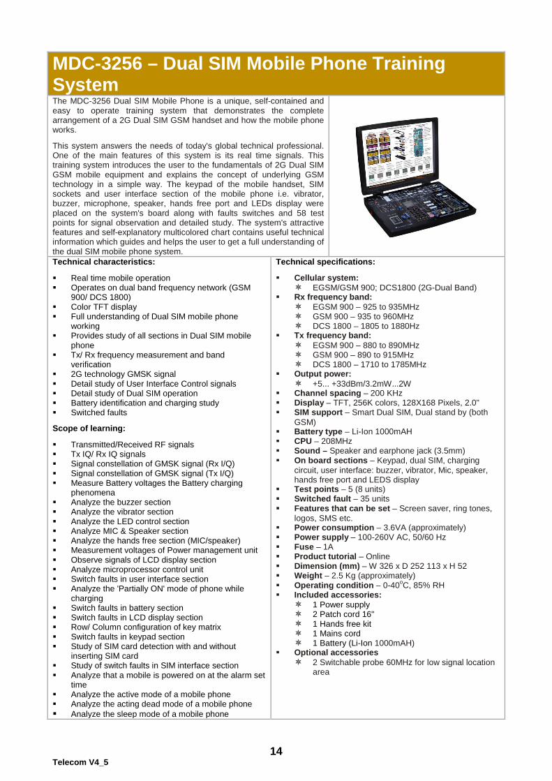
MDC-3256 – Dual SIM Mobile Phone Training System The MDC-3256 Dual SIM Mobile Phone is a unique, self-contained and easy to operate training system that demonstrates the complete arrangement of a 2G Dual SIM GSM handset and how the mobile phone works. This system answers the needs of today's global technical professional. One of the main features of this system is its real time signals. This training system introduces the user to the fundamentals of 2G Dual SIM GSM mobile equipment and explains the concept of underlying GSM technology in a simple way. The keypad of the mobile handset, SIM sockets and user interface section of the mobile phone i.e. vibrator, buzzer, microphone, speaker, hands free port and LEDs display were placed on the system's board along with faults switches and 58 test points for signal observation and detailed study. The system's attractive features and self-explanatory multicolored chart contains useful technical information which guides and helps the user to get a full understanding of the dual SIM mobile phone system.
Technical characteristics: Real time mobile operation Operates on dual band frequency network (GSM
900/ DCS 1800) Color TFT display Full understanding of Dual SIM mobile phone
working Provides study of all sections in Dual SIM mobile
phone Tx/ Rx frequency measurement and band
verification 2G technology GMSK signal Detail study of User Interface Control signals Detail study of Dual SIM operation Battery identification and charging study Switched faults Scope of learning: Transmitted/Received RF signals Tx IQ/ Rx IQ signals Signal constellation of GMSK signal (Rx I/Q) Signal constellation of GMSK signal (Tx I/Q) Measure Battery voltages the Battery charging
phenomena Analyze the buzzer section Analyze the vibrator section Analyze the LED control section Analyze MIC & Speaker section Analyze the hands free section (MIC/speaker) Measurement voltages of Power management unit Observe signals of LCD display section Analyze microprocessor control unit Switch faults in user interface section Analyze the 'Partially ON' mode of phone while
charging Switch faults in battery section Switch faults in LCD display section Row/ Column configuration of key matrix Switch faults in keypad section Study of SIM card detection with and without
inserting SIM card Study of switch faults in SIM interface section Analyze that a mobile is powered on at the alarm set
time Analyze the active mode of a mobile phone Analyze the acting dead mode of a mobile phone Analyze the sleep mode of a mobile phone
Technical specifications: Cellular system:
EGSM/GSM 900; DCS1800 (2G-Dual Band) Rx frequency band:
EGSM 900 – 925 to 935MHz GSM 900 – 935 to 960MHz DCS 1800 – 1805 to 1880Hz
Tx frequency band: EGSM 900 – 880 to 890MHz GSM 900 – 890 to 915MHz DCS 1800 – 1710 to 1785MHz
Output power: +5... +33dBm/3.2mW...2W
Channel spacing – 200 KHz Display – TFT, 256K colors, 128X168 Pixels, 2.0" SIM support – Smart Dual SIM, Dual stand by (both
GSM) Battery type – Li-Ion 1000mAH CPU – 208MHz Sound – Speaker and earphone jack (3.5mm) On board sections – Keypad, dual SIM, charging
circuit, user interface: buzzer, vibrator, Mic, speaker, hands free port and LEDS display
Test points – 5 (8 units) Switched fault – 35 units Features that can be set – Screen saver, ring tones,
logos, SMS etc. Power consumption – 3.6VA (approximately) Power supply – 100-260V AC, 50/60 Hz Fuse – 1A Product tutorial – Online Dimension (mm) – W 326 x D 252 113 x H 52 Weight – 2.5 Kg (approximately) Operating condition – 0-40oC, 85% RH Included accessories:
1 Power supply 2 Patch cord 16" 1 Hands free kit 1 Mains cord 1 Battery (Li-Ion 1000mAH)
Optional accessories 2 Switchable probe 60MHz for low signal location
area
15 Telecom V4_5
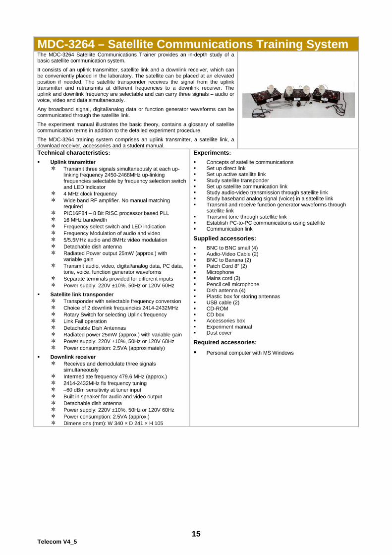
MDC-3264 – Satellite Communications Training System The MDC-3264 Satellite Communications Trainer provides an in-depth study of a basic satellite communication system.
It consists of an uplink transmitter, satellite link and a downlink receiver, which can be conveniently placed in the laboratory. The satellite can be placed at an elevated position if needed. The satellite transponder receives the signal from the uplink transmitter and retransmits at different frequencies to a downlink receiver. The uplink and downlink frequency are selectable and can carry three signals – audio or voice, video and data simultaneously.
Any broadband signal, digital/analog data or function generator waveforms can be communicated through the satellite link.
The experiment manual illustrates the basic theory, contains a glossary of satellite communication terms in addition to the detailed experiment procedure.
The MDC-3264 training system comprises an uplink transmitter, a satellite link, a download receiver, accessories and a student manual.
Technical characteristics:
Uplink transmitter Transmit three signals simultaneously at each up-
linking frequency 2450-2468MHz up-linking frequencies selectable by frequency selection switch and LED indicator
4 MHz clock frequency Wide band RF amplifier. No manual matching
required PIC16F84 – 8 Bit RISC processor based PLL 16 MHz bandwidth Frequency select switch and LED indication Frequency Modulation of audio and video 5/5.5MHz audio and 8MHz video modulation Detachable dish antenna Radiated Power output 25mW (approx.) with
variable gain Transmit audio, video, digital/analog data, PC data,
tone, voice, function generator waveforms Separate terminals provided for different inputs Power supply: 220V ±10%, 50Hz or 120V 60Hz
Satellite link transponder Transponder with selectable frequency conversion Choice of 2 downlink frequencies 2414-2432MHz Rotary Switch for selecting Uplink frequency Link Fail operation Detachable Dish Antennas Radiated power 25mW (approx.) with variable gain Power supply: 220V ±10%, 50Hz or 120V 60Hz Power consumption: 2.5VA (approximately)
Downlink receiver Receives and demodulate three signals
simultaneously Intermediate frequency 479.6 MHz (approx.) 2414-2432MHz fix frequency tuning –60 dBm sensitivity at tuner input Built in speaker for audio and video output Detachable dish antenna Power supply: 220V ±10%, 50Hz or 120V 60Hz Power consumption: 2.5VA (approx.) Dimensions (mm): W 340 × D 241 × H 105
Experiments:
Concepts of satellite communications Set up direct link Set up active satellite link Study satellite transponder Set up satellite communication link Study audio-video transmission through satellite link Study baseband analog signal (voice) in a satellite link Transmit and receive function generator waveforms through
satellite link Transmit tone through satellite link Establish PC-to-PC communications using satellite Communication link
Supplied accessories:
BNC to BNC small (4) Audio-Video Cable (2) BNC to Banana (2) Patch Cord 8” (2) Microphone Mains cord (3) Pencil cell microphone Dish antenna (4) Plastic box for storing antennas USB cable (2) CD-ROM CD box Accessories box Experiment manual Dust cover
Required accessories:
Personal computer with MS Windows
16 Telecom V4_5
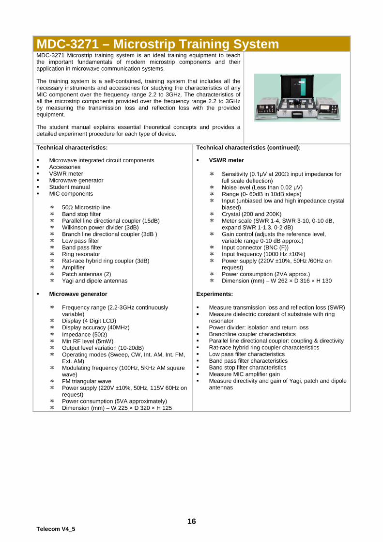
MDC-3271 – Microstrip Training System MDC-3271 Microstrip training system is an ideal training equipment to teach the important fundamentals of modern microstrip components and their application in microwave communication systems. The training system is a self-contained, training system that includes all the necessary instruments and accessories for studying the characteristics of any MIC component over the frequency range 2.2 to 3GHz. The characteristics of all the microstrip components provided over the frequency range 2.2 to 3GHz by measuring the transmission loss and reflection loss with the provided equipment. The student manual explains essential theoretical concepts and provides a detailed experiment procedure for each type of device.
Technical characteristics: Microwave integrated circuit components Accessories VSWR meter Microwave generator Student manual MIC components
50Ω Microstrip line Band stop filter Parallel line directional coupler (15dB) Wilkinson power divider (3dB) Branch line directional coupler (3dB ) Low pass filter Band pass filter Ring resonator Rat-race hybrid ring coupler (3dB) Amplifier Patch antennas (2) Yagi and dipole antennas
Microwave generator
Frequency range (2.2-3GHz continuously variable)
Display (4 Digit LCD) Display accuracy (40MHz) Impedance (50Ω) Min RF level (5mW) Output level variation (10-20dB) Operating modes (Sweep, CW, Int. AM, Int. FM,
Ext. AM) Modulating frequency (100Hz, 5KHz AM square
wave) FM triangular wave Power supply (220V ±10%, 50Hz, 115V 60Hz on
request) Power consumption (5VA approximately) Dimension (mm) – W 225 × D 320 × H 125
Technical characteristics (continued): VSWR meter
Sensitivity (0.1μV at 200Ω input impedance for full scale deflection)
Noise level (Less than 0.02 μV) Range (0- 60dB in 10dB steps) Input (unbiased low and high impedance crystal
biased) Crystal (200 and 200K) Meter scale (SWR 1-4, SWR 3-10, 0-10 dB,
expand SWR 1-1.3, 0-2 dB) Gain control (adjusts the reference level,
variable range 0-10 dB approx.) Input connector (BNC (F)) Input frequency (1000 Hz ±10%) Power supply (220V ±10%, 50Hz /60Hz on
request) Power consumption (2VA approx.) Dimension (mm) – W 262 × D 316 × H 130
Experiments: Measure transmission loss and reflection loss (SWR) Measure dielectric constant of substrate with ring
resonator Power divider: isolation and return loss Branchline coupler characteristics Parallel line directional coupler: coupling & directivity Rat-race hybrid ring coupler characteristics Low pass filter characteristics Band pass filter characteristics Band stop filter characteristics Measure MIC amplifier gain Measure directivity and gain of Yagi, patch and dipole
antennas
17 Telecom V4_5
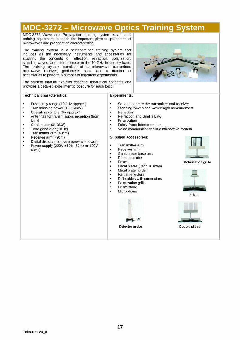
MDC-3272 – Microwave Optics Training System MDC-3272 Wave and Propagation training system is an ideal training equipment to teach the important physical properties of microwaves and propagation characteristics. The training system is a self-contained training system that includes all the necessary instruments and accessories for studying the concepts of reflection, refraction, polarization, standing waves, and interferometer in the 10 GHz frequency band. The training system consists of a microwave transmitter, microwave receiver, goniometer scale and a number of accessories to perform a number of important experiments. The student manual explains essential theoretical concepts and provides a detailed experiment procedure for each topic.
Technical characteristics: Frequency range (10GHz approx.) Transmission power (10-15mW) Operating voltage (8V approx.) Antennas for transmission, reception (horn
type) Ganiometer (0°-360°) Tone generator (1KHz) Transmitter arm (49cm) Receiver arm (49cm) Digital display (relative microwave power) Power supply (220V ±10%, 50Hz or 120V
60Hz)
Experiments: Set and operate the transmitter and receiver Standing waves and wavelength measurement Reflection Refraction and Snell’s Law Polarization Fabry-Perot interferometer Voice communications in a microwave system Supplied accessories: Transmitter arm Receiver arm Ganiometer base unit Detector probe Prism Metal plates (various sizes) Metal plate holder Partial reflectors DIN cables with connectors Polarization grille Prism stand Microphone
Polarization grille
Prism
Double slit set Detector probe
18 Telecom V4_5
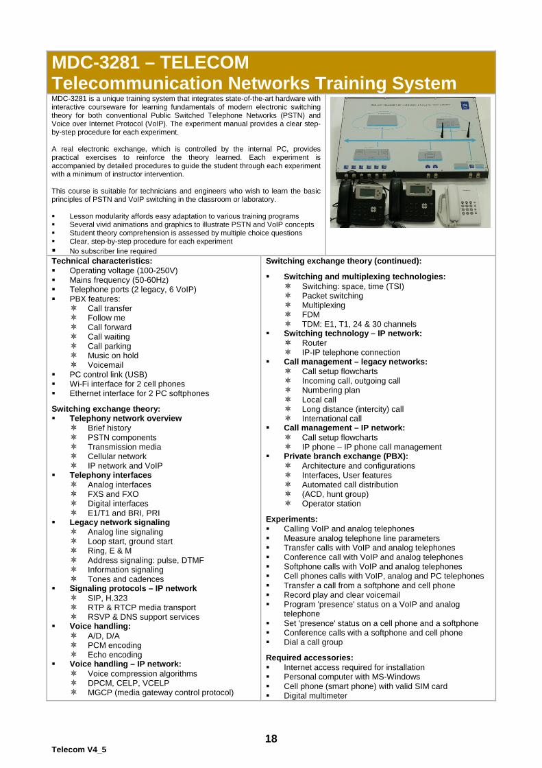
MDC-3281 – TELECOM Telecommunication Networks Training System MDC-3281 is a unique training system that integrates state-of-the-art hardware with interactive courseware for learning fundamentals of modern electronic switching theory for both conventional Public Switched Telephone Networks (PSTN) and Voice over Internet Protocol (VoIP). The experiment manual provides a clear step-by-step procedure for each experiment. A real electronic exchange, which is controlled by the internal PC, provides practical exercises to reinforce the theory learned. Each experiment is accompanied by detailed procedures to guide the student through each experiment with a minimum of instructor intervention. This course is suitable for technicians and engineers who wish to learn the basic principles of PSTN and VoIP switching in the classroom or laboratory. Lesson modularity affords easy adaptation to various training programs Several vivid animations and graphics to illustrate PSTN and VoIP concepts Student theory comprehension is assessed by multiple choice questions Clear, step-by-step procedure for each experiment No subscriber line required
Technical characteristics: Operating voltage (100-250V) Mains frequency (50-60Hz) Telephone ports (2 legacy, 6 VoIP) PBX features:
Call transfer Follow me Call forward Call waiting Call parking Music on hold Voicemail
PC control link (USB) Wi-Fi interface for 2 cell phones Ethernet interface for 2 PC softphones Switching exchange theory: Telephony network overview
Brief history PSTN components Transmission media Cellular network IP network and VoIP
Telephony interfaces Analog interfaces FXS and FXO Digital interfaces E1/T1 and BRI, PRI
Legacy network signaling Analog line signaling Loop start, ground start Ring, E & M Address signaling: pulse, DTMF Information signaling Tones and cadences
Signaling protocols – IP network SIP, H.323 RTP & RTCP media transport RSVP & DNS support services
Voice handling: A/D, D/A PCM encoding Echo encoding
Voice handling – IP network: Voice compression algorithms DPCM, CELP, VCELP MGCP (media gateway control protocol)
Switching exchange theory (continued): Switching and multiplexing technologies:
Switching: space, time (TSI) Packet switching Multiplexing FDM TDM: E1, T1, 24 & 30 channels
Switching technology – IP network: Router IP-IP telephone connection
Call management – legacy networks: Call setup flowcharts Incoming call, outgoing call Numbering plan Local call Long distance (intercity) call International call
Call management – IP network: Call setup flowcharts IP phone – IP phone call management
Private branch exchange (PBX): Architecture and configurations Interfaces, User features Automated call distribution (ACD, hunt group) Operator station
Experiments: Calling VoIP and analog telephones Measure analog telephone line parameters Transfer calls with VoIP and analog telephones Conference call with VoIP and analog telephones Softphone calls with VoIP and analog telephones Cell phones calls with VoIP, analog and PC telephones Transfer a call from a softphone and cell phone Record play and clear voicemail Program 'presence' status on a VoIP and analog
telephone Set 'presence' status on a cell phone and a softphone Conference calls with a softphone and cell phone Dial a call group Required accessories: Internet access required for installation Personal computer with MS-Windows Cell phone (smart phone) with valid SIM card Digital multimeter
19 Telecom V4_5
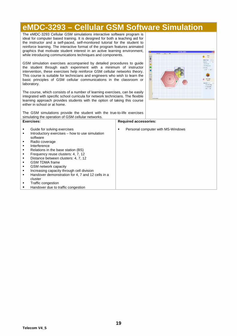
eMDC-3293 – Cellular GSM Software Simulation The eMDC-3293 Cellular GSM simulations interactive software program is ideal for computer based training. It is designed for both a teaching aid for the instructor and a self-paced, self-monitored tutorial for the student to reinforce learning. The interactive format of the program features animated graphics that motivate student interest in an active learning environment, while introducing communications techniques and components. GSM simulation exercises accompanied by detailed procedures to guide the student through each experiment with a minimum of instructor intervention, these exercises help reinforce GSM cellular networks theory. This course is suitable for technicians and engineers who wish to learn the basic principles of GSM cellular communications in the classroom or laboratory. The course, which consists of a number of learning exercises, can be easily integrated with specific school curricula for network technicians. The flexible learning approach provides students with the option of taking this course either in school or at home. The GSM simulations provide the student with the true-to-life exercises simulating the operation of GSM cellular networks.
Exercises: Guide for solving exercises Introductory exercises – how to use simulation
software Radio coverage Interference Relations in the base station (BS) Frequency reuse clusters: 4, 7, 12 Distance between clusters: 4, 7, 12 GSM TDMA frame GSM network capacity Increasing capacity through cell division Handover demonstration for 4, 7 and 12 cells in a
cluster Traffic congestion Handover due to traffic congestion
Required accessories: Personal computer with MS-Windows
20 Telecom V4_5
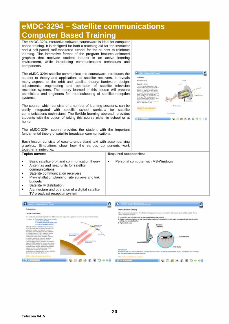
eMDC-3294 – Satellite communications Computer Based Training The eMDC-3294 interactive software courseware is ideal for computer based training. It is designed for both a teaching aid for the instructor and a self-paced, self-monitored tutorial for the student to reinforce learning. The interactive format of the program features animated graphics that motivate student interest in an active learning environment, while introducing communications techniques and components. The eMDC-3294 satellite communications courseware introduces the student to theory and applications of satellite receivers. It reveals many aspects of the orbit and satellite theory; hardware; design; adjustments; engineering and operation of satellite television reception systems. The theory learned in this course will prepare technicians and engineers for troubleshooting of satellite reception systems. The course, which consists of a number of learning sessions, can be easily integrated with specific school curricula for satellite communications technicians. The flexible learning approach provides students with the option of taking this course either in school or at home. The eMDC-3294 course provides the student with the important fundamental theory of satellite broadcast communications. Each lesson consists of easy-to-understand text with accompanying graphics. Simulations show how the various components work together in networks.
Topics covers: Basic satellite orbit and communication theory Antennas and head units for satellite
communications Satellite communication receivers Pre-installation planning: site surveys and link
budgets Satellite IF distribution Architecture and operation of a digital satellite
TV broadcast reception system
Required accessories: Personal computer with MS-Windows
21 Telecom V4_5
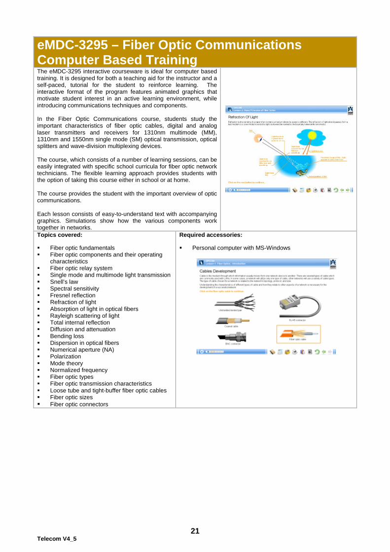
eMDC-3295 – Fiber Optic Communications Computer Based Training The eMDC-3295 interactive courseware is ideal for computer based training. It is designed for both a teaching aid for the instructor and a self-paced, tutorial for the student to reinforce learning. The interactive format of the program features animated graphics that motivate student interest in an active learning environment, while introducing communications techniques and components. In the Fiber Optic Communications course, students study the important characteristics of fiber optic cables, digital and analog laser transmitters and receivers for 1310nm multimode (MM), 1310nm and 1550nm single mode (SM) optical transmission, optical splitters and wave-division multiplexing devices. The course, which consists of a number of learning sessions, can be easily integrated with specific school curricula for fiber optic network technicians. The flexible learning approach provides students with the option of taking this course either in school or at home. The course provides the student with the important overview of optic communications. Each lesson consists of easy-to-understand text with accompanying graphics. Simulations show how the various components work together in networks.
Topics covered: Fiber optic fundamentals Fiber optic components and their operating
characteristics Fiber optic relay system Single mode and multimode light transmission Snell’s law Spectral sensitivity Fresnel reflection Refraction of light Absorption of light in optical fibers Rayleigh scattering of light Total internal reflection Diffusion and attenuation Bending loss Dispersion in optical fibers Numerical aperture (NA) Polarization Mode theory Normalized frequency Fiber optic types Fiber optic transmission characteristics Loose tube and tight-buffer fiber optic cables Fiber optic sizes Fiber optic connectors
Required accessories: Personal computer with MS-Windows
22 Telecom V4_5
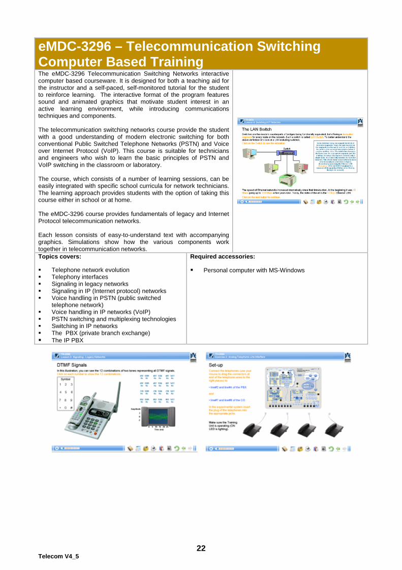
eMDC-3296 – Telecommunication Switching Computer Based Training The eMDC-3296 Telecommunication Switching Networks interactive computer based courseware. It is designed for both a teaching aid for the instructor and a self-paced, self-monitored tutorial for the student to reinforce learning. The interactive format of the program features sound and animated graphics that motivate student interest in an active learning environment, while introducing communications techniques and components. The telecommunication switching networks course provide the student with a good understanding of modern electronic switching for both conventional Public Switched Telephone Networks (PSTN) and Voice over Internet Protocol (VoIP). This course is suitable for technicians and engineers who wish to learn the basic principles of PSTN and VoIP switching in the classroom or laboratory. The course, which consists of a number of learning sessions, can be easily integrated with specific school curricula for network technicians. The learning approach provides students with the option of taking this course either in school or at home. The eMDC-3296 course provides fundamentals of legacy and Internet Protocol telecommunication networks. Each lesson consists of easy-to-understand text with accompanying graphics. Simulations show how the various components work together in telecommunication networks.
Topics covers: Telephone network evolution Telephony interfaces Signaling in legacy networks Signaling in IP (Internet protocol) networks Voice handling in PSTN (public switched
telephone network) Voice handling in IP networks (VoIP) PSTN switching and multiplexing technologies Switching in IP networks The PBX (private branch exchange) The IP PBX
Required accessories: Personal computer with MS-Windows
SES Training LABs
The training labs are based on learning-by-doing, which makes students learn more quickly and remember what they have studied by performing practical experiments. They provide the students high profession skills and the knowledge on how to improve their chance of employment and earning capacity. The manuals and courseware that accompany each course provide the theory background and experiments. Electronics Training Lab This modular laboratory is aimed for the Electronics profession, but also for technology disciplines that are also based in electronics, such as: Electricity, Mechanics, Automotive, Robotics, Automation, Process control. Autotronics Training Lab This modular laboratory is aimed for the five stages that comprise the automotive program: Basic and automotive electronics, Car sub-systems simulators, Car sub-systems demonstrators, Car diagnostic and troubleshooting methods, Troubleshooting faults in a real car. Mechatronics Training Lab This modular laboratory is aimed for the mechatronics program which includes the following disciplines: Basic electronics, Pneumatics systems, Hydraulics systems, CNC machines. Refrigeration and Air-Conditioning Training Lab The Refrigeration and Air-Conditioning training lab covers actual components and their interconnection, related functions, operation, diagnosis and repair methods through safe, hands-on practical activities. Technology Preparation Training Lab The Technology Preparation (Tech Prep) laboratory is a classroom-integrated laboratory consisting of educational modules covering a wide range of subjects such as: Green energy, Computerized systems, Basic electronics, Basic communication, Mechanical systems. Science Training Labs These laboratories (for primary, secondary and high schools) introduce the students to the computerized sensors world, nature and industry processes and nature laws. It will help them understand modern technologies such as: home and medical appliances, wearing sensors, precise agriculture and more. Robotics Training Labs The robotics programs (for primary, secondary and high schools) help students to build innovation and creativity skills. The idea is to make the students understand how systems work, to believe that they can improve them and be able to realize their ideas. MultiCenter Training Lab The MultiCenter offers a variety of selected interactive learning environments, with a large range of topics and activities such as: Science, Technology, Graphic Design, Digital Music, Robotics, Computer Technologies and much more for all sectors of society, cultures, different socio-economic groups and different age groups – from very young children to senior citizens.
Our Training Labs:
SCIENCE
ROBOTICS
ELECTRONICS
ELECTRICITY
TELECOMMUINCATION
AUTOTRONICS
MECHATRONICS
MULTICENTER
SCIENCE & ROBOTICS
TECHNOLOGY PREPARATION
REFRIGIRATION & AIR-CONDITIONING
TELE
CO
M


