Document ID: TELE-0-1000 Revision: 1 Date: 12/02/2010 Telecommunications Subsystem Overview Andrew Maine Branden Ghena [email protected][email protected]Revision History Revision Revised By Revised On Revisions Made --- Branden Ghena --- Legacy Release. 1 Andrew Maine 12/02/2010 Updated to match current specifications. This Document Satisfies The Following Requirements ID Requirement Met See Pages Verified See Pages TELE1-3 The telecommunications subsystem shall be capable of ceasing transmission if it is determined the satellite is creating harmful interference. ADM 2 ADM 2 Faculty Advisor Project Manager Team Leader
Table of Tables .............................................................................................................................................. ii
Table of Figures ............................................................................................................................................. ii
Table of Equations ........................................................................................................................................ ii
Frequency Allocation ................................................................................................................................ 6
Ground Station Design .............................................................................................................................. 7
Appendix I – Ground Station Location Data................................................................................................... i
Appendix II – Ground Station Components and Criteria ............................................................................. iii
Appendix III – Interface Control ................................................................................................................... iv
Telecommunications Subsystem Overview Page ii
Table of Tables Table 1: Telecommunications System Requirements ................................................................................... 1 Table 2: Component Diagram of Ground Station ......................................................................................... 9
Table of Figures Figure 1: ISIS TRXUV Low Speed Radio .................................................................................................... 3 Figure 2: LSR Communication Flowchart .................................................................................................... 4 Figure 3: MHX-2420 High Speed Radio ...................................................................................................... 4 Figure 4: HSR Communication Flowchart ................................................................................................... 5 Figure 5: Telecom System Communication Flowchart ................................................................................ 6 Figure 6: Component Diagram of Ground Station ........................................................................................ 7 Figure 7: Talk Time per Month by Altitude .................................................................................................. i Figure 8: Talk Time per Month by Inclination ............................................................................................. ii
Table of Equations Equation 1: Data Rate Transfer for LSR ....................................................................................................... 2 Equation 2: Data Rate Transfer for HSR ...................................................................................................... 2
Telecommunications Subsystem Overview Page 1
Introduction
Communication between the satellite and the Michigan Tech ground station are necessary for a successful mission. To this end, the Oculus-ASR project is employing a system of communication which relies on both higher speed and lower speed radio frequencies. The Low Speed Radio (LSR) subsystem is set up in order to send and receive satellite control information. The High Speed Radio (HSR) subsystem is designed to transmit images taken by the satellite. Together, these subsystems compose the entirety of the Telecommunications subsystem.
Requirements
The requirements for the Telecommunications system are based upon the Mission and System Requirements specified in the Requirements Verification Matrix.
Table 1: Telecommunications System Requirements
1. The telecom subsystem shall be capable of receiving 165 kilobits (estimated largest
code block) in a single communication window of length of 9 minutes in order to
upload code.
2. The telecom subsystem shall be capable of transmitting 64 megabits (40 images from
each camera) in a single communication window of length of 9 minutes from the
Oculus-ASR to the ground station.
3. The telecommunications subsystem shall be capable of ceasing transmission if it is
determined the satellite is creating harmful interference.
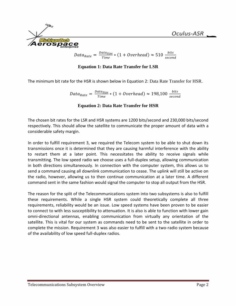
Requirement 1 applies to the LSR subsystem, requirement 2 applies to the HSR subsystem, requirement 3 is necessary for both. In order to fulfill requirements 1 and 2, a minimum bit rate was needed from both the LSR and HSR systems. The data rate needed is based on the talk time window for the satellite, a maximum of 9 minutes before the subtraction of an assumed loss of 2 minutes as a safety factor. As for the amount of data required to be sent, a 30% safety factor was included. The minimum bit rate for the LSR is defined below in Equation 1: Data Rate Transfer for LSR.
Telecommunications Subsystem Overview Page 2
( )
Equation 1: Data Rate Transfer for LSR
The minimum bit rate for the HSR is shown below in Equation 2: Data Rate Transfer for HSR.
( )
Equation 2: Data Rate Transfer for HSR
The chosen bit rates for the LSR and HSR systems are 1200 bits/second and 230,000 bits/second respectively. This should allow the satellite to communicate the proper amount of data with a considerable safety margin. In order to fulfill requirement 3, we required the Telecom system to be able to shut down its transmissions once it is determined that they are causing harmful interference with the ability to restart them at a later point. This necessitates the ability to receive signals while transmitting. The low speed radio we choose uses a full-duplex setup, allowing communication in both directions simultaneously. In connection with the computer system, this allows us to send a command causing all downlink communication to cease. The uplink will still be active on the radio, however, allowing us to then continue communication at a later time. A different command sent in the same fashion would signal the computer to stop all output from the HSR. The reason for the split of the Telecommunications system into two subsystems is also to fulfill these requirements. While a single HSR system could theoretically complete all three requirements, reliability would be an issue. Low speed systems have been proven to be easier to connect to with less susceptibility to attenuation. It is also is able to function with lower gain omni-directional antennas, enabling communication from virtually any orientation of the satellite. This is vital for our system as commands need to be sent to the satellite in order to complete the mission. Requirement 3 was also easier to fulfill with a two-radio system because of the availability of low speed full-duplex radios.
Telecommunications Subsystem Overview Page 3
Low Speed Radio Subsystem
Figure 1: ISIS TRXUV Low Speed Radio
The LSR subsystem is used for control of the satellite. Communication will be bi-directional. The core of the system is the ISIS TRXUV transceiver. This radio functions on the UHF band for uplink and the VHF band for downlink, and includes full-duplex communication. This radio will receive input from the Comtelco A4641 antenna. This input will be modulated with Audio Frequency-Shift Keying (AFSK). The output of the radio will be sent to the NP507 amplifier, which is directly connected to the Comtelco A1611 antenna. The TRXUV will be in full communication with the main on-board computer through the use of an I2C bus. For a more complete description of the design of the LSR subsystem, see document TELE-1-1000-LSRDesignDocument-R1.docx
Telecommunications Subsystem Overview Page 4
Earth Satellite
Figure 2: LSR Communication Flowchart
High Speed Radio Subsystem
Figure 3: MHX-2420 High Speed Radio
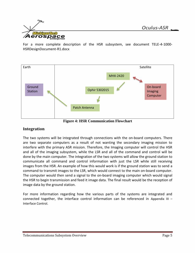
The HSR subsystem is used for image transfer from the satellite. Communication will only occur in the downlink form. The base radio we are using for high speed communication is the Microhard MHX-2420. The radio functions on a frequency of 2.4 GHz and will transmit at 230,000 bits/second. One useful feature of the MHX-2420 is its ability to create an ad-hoc direct connection with another radio of the same type, easing communication with the ground station. The radio will receive signals from the on-board imaging computer which it will then transmit to the Ophir 5302015 amplifier. The amplifier will be directly connected to the Comtelco Patch Antenna in order to boost the gain and create a link with the ground station.
On-board Main Computer
Ground Station
TRXUV
NP507
Comtelco A1611
Comtelco A4641
Telecommunications Subsystem Overview Page 5
For a more complete description of the HSR subsystem, see document TELE-4-1000-HSRDesignDocument-R1.docx
Earth Satellite
Figure 4: HSR Communication Flowchart
Integration
The two systems will be integrated through connections with the on-board computers. There are two separate computers as a result of not wanting the secondary imaging mission to interfere with the primary ASR mission. Therefore, the Imaging computer will control the HSR and all of the imaging subsystem, while the LSR and all of the command and control will be done by the main computer. The integration of the two systems will allow the ground station to communicate all command and control information with just the LSR while still receiving images from the HSR. An example of how this would work is if the ground station was to send a command to transmit images to the LSR, which would connect to the main on-board computer. The computer would then send a signal to the on-board imaging computer which would signal the HSR to begin transmission and feed it image data. The final result would be the reception of image data by the ground station. For more information regarding how the various parts of the systems are integrated and connected together, the interface control information can be referenced in Appendix III –
Interface Control.
On-board Imaging Computer
MHX-2420
Ground Station
Ophir 5302015
Patch Antenna
Telecommunications Subsystem Overview Page 6
Earth Satellite
Figure 5: Telecom System Communication Flowchart
Frequency Allocation
Another important portion of the Telecommunications design was accounting for frequency allocation so as to avoid unwanted interference with our communications with the satellite. As the bands our satellite operates at fall under the jurisdiction of the International Amateur Radio Union (IARU) and each student on the Telecommunications team has an Amateur Radio license, the operation and testing of our satellite is operable under the authorization of the amateur-satellite service. In addition, we have submitted a frequency coordination request with the IARU in order to ensure that we do not cause harmful interference to stations around the world and in turn to not receive harmful interference from them which could result in a mission failure. Despite the fact that our satellite falls under the amateur-satellite service provided by the International Amateur Radio Union (IARU), we have applied for an experimental license (Form 442) with the Federal Communications Commission (FCC). This was done in order to ensure that the satellite remained licensed to operate at the appropriate radio bands despite the fact that personnel turnover in the enterprise is so high from being a student organization staffed with volunteers and there may not always be students with amateur licenses to operate the satellite’s radios. In addition, the FCC license appropriately places responsibility on the organization as a whole rather than one or two students if the satellite causes problems through unwanted interference.
On-board Main Computer
HSR Subsystem
Ground Station
LSR Subsystem
On-board Imaging Computer
Telecommunications Subsystem Overview Page 7
Ground Station Design
Introduction
As an integral part of a successful mission, a ground station will need to be created in order to control communication with the satellite. It will require the ability to track Oculus's position in the sky and to orient itself optimally to create a communication link. It will also require proper antennas, radio systems, amplifiers, and modems to capture and translate data received as well as to send data.
Overall Design
The general design for our ground station breaks up into various of-the-shelf components which will together form the complete station (See Figure 6), a main computer will make the necessary calculations to determine Oculus's current location and will communicate with a motor controller to angle the antennas toward the satellite. It will also communicate with the high speed and low speed radios to receive and send data. The low speed communication will require a modem to modulate transmissions from the ground station into AFSK. It will be bi-directional to allow health information from the satellite to be gathered by the main computer and commands to be sent to the satellite. The high speed communication system will allow for downlink of pictures from the camera system on the satellite.
Figure 6: Component Diagram of Ground Station
Tracking Requirements The requirements for the tracking portion of the ground station will be for it to accurately determine the location of the satellite as well as to be able to orient itself for proper communication. For tracking purposes, the Nova software package will be used. It will allow us
Telecommunications Subsystem Overview Page 8
to input know orbit data and will handle the computation for determining current satellite location. Using data from this program, a ground station control program created by our software team will handle communication with a motor controller which will handle the specific power needs of the rotors. Two rotors (azimuth and elevation) will be required to allow for 2 degrees of freedom in the ground station. In combination, they can be used to ensure that we will be able to track Oculus-ASR no matter where it is in the sky. Care will need to be taken in physical construction of the station to ensure that it is able to use full 360 degrees of azimuth rotation as well as 90 degrees of elevation change. Orbit data for Oculus-ASR will be calculated based on information in the Two-Line Element sets (TLEs) released by NORAD. The Satellite Tool Kit (STK) program created by Analytical Graphics, Inc. will allow us to input the TLEs and will calculate the exact position of the satellite as well as when access times with it will occur for our Ground Station. TLE data released by NORAD is frequently updated to kept perturbations of the satellite's orbit from affecting model's too greatly.
Communication Requirements
Our communication requirements are based on the fundamental Telecom satellite requirements (See Table 2). In order to fulfill Requirements 1 and 3 as well as to obtain general satellite health information, a low speed communication system will be necessary in the ground station. This system will use an amateur radio for data transfer. It must be capable of operating at 9600 baud as well as transmitting on the 70 cm band and receiving on the 2 m band. It will be attached to a 2 m Yagi antenna for reception and a 70 cm Yagi antenna for transmission, both of which will be linearly polarized. It will require a modem in order to modulate our transmissions using AFSK to Oculus-ASR. The audio output of the low speed receiver will be connected to the main computer allowing an ISIS software package to convert the BPSK modulated signal into text. In order to fulfill Requirement 2, a high speed communication system will also be needed. This system will use a Microhard MHX-2420 radio which will automatically sync and receive from the MHX-2420 on the satellite. All antennas on the ground station will be physically connected to the rotors in such a way as to allow them to move to orient themselves optimally for communication.
Telecommunications Subsystem Overview Page 9
Table 2: Component Diagram of Ground Station
1. The Telecom subsystem shall be capable of receiving 165 kilobits
(estimated largest code block) in a single communication window of
length of 9 minutes in order to upload code.
2. The Telecom subsystem shall be capable of transmitting 64 megabits
(40 images from each camera) in a single communication window of
length of 9 minutes from the Oculus-ASR to the ground station.
3. The telecommunications subsystem shall be capable of ceasing
transmission at any time if it is determined the satellite is creating
harmful interference.
More information regarding the components involved with the planned ground station can be found in Appendix II – Ground Station Components and Criteria.
Location Requirements
The physical location of the ground station is very important to a successful mission. It needs to be properly situated to provide both easy access for Aerospace Enterprise team members and to have maximum duration and strength of connection with Oculus-ASR. It must also be placed so that there will not be nearby obstructions to block signal from the satellite. Based on the assumption that we will get a suitable orbit for communication with Houghton, we are planning on setting up our ground station in coordination with the Husky Amateur Radio Club (HARC). The HARC is made up of amateur radio operators from the area and since our satellite operates on amateur band frequencies, they already have facilities which will help in the setup of our ground station. A possible location for the ground station would be the roof of a building on Michigan Tech's campus, either the Mechanical Engineering and Engineering Mechanics Building (MEEM) for its height or Wadsworth Hall where the HARC already maintains an amateur radio communications station. Either of these choices would allow easy access for students while maintaining the height needed to bypass any obstructions in the area. Working in collaboration with the HARC is especially important and helpful to our needs because the HARC already maintains a ground station for low-speed communication with satellites. Their setup includes a station with both azimuth and elevation rotors which uses both 2 m and 70 cm antennas. This station is connected to a computer with Nova installed on it for controlling the rotors. If adjusted properly, this already existing station should fulfill our low speed communications requirements and function as a good example for the construction of our own high speed communication setup.
Telecommunications Subsystem Overview Page 10
We believe that the assumption that our orbit will be accessible from the Houghton area is reasonable based on data from the STK program. We used the orbital characteristics from the FASTRAC satellite (72º inclination with 650 km altitude) in combination with a Houghton based Ground Station over the course of a 90 day mission. Based on this information, STK calculated 773 distinct access times over the course of the mission, with 500 of them greater than 9 minutes in duration. This is important, because a 9 minute access time (with a two-minute buffer for communications link) is the assumption used in our system overview to calculate our necessary upload speed. Removing the two-minute buffer period from each of the access times greater than 9 minutes creates a total talk-time for the 90 day mission of 86 hours. Due to actual orbit characteristics depending on our launch vehicle, we cannot finalize any decisions about the location of our ground station. It is possible that Michigan Tech campus would not be a reliable location for it, in which case another location would need to be found. One possible solution for such a problem would be a partnership with another university located more optimally to allow us to locate our ground station on or near their campus. Graphs detailing research done on possible locations for our ground station in terms of talk time per month for each site in relation to both altitude and inclination can be found in Appendix I.
Testing Plans
Advance testing will be required in order to ensure that our ground station will fulfill its requirements during the mission. This test will be split up into communication testing, tracking testing, and full integration testing.
Communication Testing
The first aspect of the Ground Station to be tested is establishing a link with another set of radios. The first link should be established using voice because this is generally the easiest to setup using amateur equipment. This also helps to ensure that the antennas and power settings are in the correct range. Next the radios should be tested to establish a digital link (a.k.a. packet radio). The parameters for the modem setup should be identical to those of the satellite/Ground Station to help find any issues. Once this link has been established it can be reasonable to assume that the link works well.
Telecommunications Subsystem Overview Page 11
The next step is to test the digital (packet) link using the software on the main computer. This will help bring forward issues not previously found through software testing.
Tracking Testing
The rotor should be calibrated to determine a reference point. This point could be picked to be due north pointing at the horizon. The next step would be to ensure that the rotors are able to rotate without obstruction and ensure that all of the feed lines have the proper amount of slack. It is suggested to perform this test with manual controls and an observer to watch the rotors/antennas for proper movement. The last portion of the rotor testing should include having the software, such as Nova, automatically control the rotors for a given satellite pass. This can be either a simulated satellite or a real satellite. Here too, the rotor positions should be observed to ensure that it is tracking in the correct direction. These tests will ensure that the rotors will be able to automatically point the antennas at the satellite to help ensure the best gain patterns of the antennas are directed towards the satellite.
Full Integration Testing
All of the previous testing has tested each part of the station piece-wise. This test will bring everything together and ensure that the system works as a whole. A suitable satellite shall be selected that is active and is compatible with our Ground Station in frequency, data rate, and orbital parameters. The tracking software should be set to automatically track the satellite with the rotors and control the frequency deviation on the radios due to Doppler Effect. It is probable that an amateur will have to manually establish a link with the satellite. However a link should be established and some form of data transfer/communication with the satellite should take place to demonstrate the functionality of the Ground Station as a whole system.
Telecommunications Subsystem Overview Page 12
Conclusion
The ground station is an essential component to a successful mission. It will need to handle all communication with the satellite reliably. We believe that its off-the-shelf component design together with appropriate testing will allow us to accomplish this goal.
Conclusion
In conclusion, the Telecommunications system is vital to the success of the Oculus-ASR project. We believe that the split of the system into low speed and high speed subsystems will help fulfill our design requirements and allow for proper communication with the ground. Each part separately plays a small role, but as a system they directly lead to the success of the satellite.
Telecommunications Subsystem Overview Page i
Appendix I – Ground Station Location Data
Figure 7: Talk Time per Month by Altitude
0
50000
100000
150000
200000
250000
Talk
Tim
e (
seco
nd
s)
Inclination and Altitude
Access Times Over 1 Month: By Altitude
Austin
CalTech
CapeCanveral
DC
Hawaii
Houghton
NMState
PennState
PolyTech
SantaClara
Telecommunications Subsystem Overview Page ii
Figure 8: Talk Time per Month by Inclination
0
50000
100000
150000
200000
250000
Talk
Tim
e (
seco
nd
s)
Inclination and Altitude
Access Times Over 1 Month: By Inclination
Austin
CalTech
CapeCanveral
DC
Hawaii
Houghton
NMState
PennState
PolyTech
SantaClara
Telecommunications Subsystem Overview Page iii
Appendix II – Ground Station Components and Criteria
Hardware
o Main Computer
Windows Operating System
o Controller
Control rotor system with azimuth and elevation rotor
Connect able to a computer
o Rotors
1 rotor to control azimuth
1 rotor to control elevation
Compatible with controller
o Low Speed Radio
Transmit on 70 cm band
Receive on 2 m band
Operate at 9600 baud
o High Speed Radio
Transmit and receive at 2.4 GHz
Data Rate > 198 kilobits/second
o Low Speed Antennas
Yagi
70cm band and 2m band
o High Speed Antenna
Frequency 2.4GHz
Software
o Windows Operating System
o Nova
o STK
o ISIS Software Package
Telecommunications Subsystem Overview Page iv
Appendix III – Interface Control Component – High Speed Radio - MHX-2420 Electrical & Data Interface Connector Name/ID – TEL-HSR-9-P-F2 Connector Type – DB9
Pin #
Name Power or Data
Voltage Current Signal Type
Speed (baud)
Packet Size
Comments
1 HS_RADIO_THERM Data Analog Analog
2
3 HS_RADIO_+5V@1 Power +5V DC
4 HS_ RADIO_+5V@2 Power +5V DC
5 HS_ RADIO_+5V@3 Power +5V DC
6 HS_ RADIO_RTN@1 Power 0V DC
7 HS_ RADIO_RTN@1 Power 0V DC
8 HS_RADIO_RTN@1 Power 0V DC
9 HS_RADIO_THERM_RTN Data Analog Analog
Telecommunications Subsystem Overview Page v
Connector Name/ID - TEL-HSR-15-D-M2 Connector Type – DB15
Pin #
Name Power or Data
Voltage Current Signal Type Speed (baud)
Packet Size
Comments
1
2 HS_RADIO_TX Data Digital 230kbps
3 HS_RADIO_RX Data Digital 230kbps
4
5 HS_RADIO_TX/RX_GND Data Digital
6 HS_RADIO_ENABLE Data Digital Active Low
7
8 HS_RADIO_RESET Data Digital Active Low
9 HS_RADIO_LGND Data 0V <50mA Digital
10
11
12
13
14
15
Telecommunications Subsystem Overview Page vi
Connector Name/ID – TEL-HSR-1-F Connector Type – SMA