36
TELECONTROL TECHNOLOGY Power Grid Products and Solutions

TELECONTROL TECHNOLOGY Power Grid Products and Solutions

INTELLIGENT TELECONTROLSystem Provides Long-Term Investment Protection
Transitioning to renewable energy is great for the environment; however, it presents tremendous challenges to energy suppliers, network operators and the grids themselves. It sounds so simple, yet the truth is that decen-tralization has required a complete 180 when it comes to electrical generation. And this has engineers rethinking:
• The monitoring of supply points and substations• Regulation of voltage, frequencies, reactive power and more• Secure archiving, evaluation and transmission of data• IT Security — Protected data transmission between a
decentralized station and control system
In fact, both a white paper from the German Energy and Water Industry Association (BDEW) as well as the IT security catalog issued by the Federal Network Agency provide comprehensive guidelines on IT security. And the WAGO-I/O-SYSTEM 750 is ready to accommodate these security requirements. Thus, the following features have already been implemented in select controllers:
• OpenVPN encryption• IPsec encryption• MAC filter• Separate TCP/IP ports
All of these requirements are also placed on other supply technology sectors, such as gas, water and heat. And this focus on security has made the WAGO-I/O-SYSTEM “the automation system for every application.”
750-880/025-001750-880/025-002
750-880/040-001
– 2 –

SCALABLE CONTROLLERS for Telecontrol Technology
750-8206/025-001
750-8202/025-001750-8202-025-002
PLC for Telecontrol Technology
Item No. 750-880/ 040-001
750-880/025-001750-880/025-002*
750-8202/025-001750-8202/025-001*
750-8206/ 025-001
Approvals UL 508, 1, GL
CPU ARM 9; 80 MHz Cortex A8; 600 MHz
Interfaces
LAN 2 x RJ-45 2 x RJ-45/Dual LAN
I/O interfaces (serial) — 1 x RS-232, 1 x D-Sub 9, socket (switchable)
I/O interfaces (USB) —
Memory
Non-volatile memory (retain) 32 KB 128 KB
Program memory 1 MB 16 MB
Data memory 1 MB 64 MB
Memory expansion SD and SDHC up to 32 GB
Fieldbus (optional) —PROFIBUS DP Slave, CAN, CANopen
Programming WAGO-I/O-PRO v2.3
Telecontrol protocols Modbus/TCP (UDP), EtherNet/IP, IEC 60870-5-101/-103/-104, IEC 61850 / 61400-25 3964R/RK512
Operating temperature -40 °C … +70 ° C -20 °C … +60 ° C
EMC: 1-Immunity to interference acc. EN 60870-2-1 acc. EN 61000-6-2
EMC: 1-Emission of interference acc. EN 60870-2-1 per EN 61000-6-4
*Number of modules: 4
– 3 –

SMART GRID — AN INTELLIGENT NETWORK FOR SMART SOLUTIONS
CHP PLANTS
INDUSTRY
CONSUMERS
LOCAL NETWORK STATIONS
SUBSTATIONS
CONVENTIONAL POWER SUPPLIERS
eMOBILITY
– 4 –

SMART GRID — AN INTELLIGENT NETWORK FOR SMART SOLUTIONS
SOLAR FARMS
WIND FARMS
BIOGAS PLANTS
PUMPED- STORAGE PLANTS
– 5 –

SMART GRID CHALLENGE
Confined spaces in existing systems Minimizing integration efforts
Secure communication
Connecting numerous interfaces
LON®
IEC 60870/61850/61400
– 6 –

INTEGRATING DECENTRALIZED SUPPLIERSEasy, Efficient and Cost-Effective
The Compact and Economical Telecontrol Solution for Plant Control and Monitoring
The revised Renewable Energy Sources Act (EEG) mandates that photovoltaic (PV) plants must have a technical interface for the network operator that enables remote-controlled power reduction. In the future, all plants (PV, wind, biogas) must disclose feed-in power data to the network operator.
• Remote control (direct marketing) per EEG • Output reduction usually occurs in four increments —
0 %, 30 %, 60 % and 90 % or multi-level cos ϕ regulation• Delivery of the current feed-in rate as measured or meter data• System provides long-term investment protection• The scalable WAGO-I/O-SYSTEM 750 allows system
operators to easily pace government regulations via flexible hardware and software configurations
IEC-compliant communication per IEC 60870-5-101/-104
Control center
Wind farmsSolar farms Biogas plants
– 7 –

VIRTUAL POWER PLANTSControl and Networking
Hardware benefits:• Connecting generator, consumer and
storage system via one controller• Multiple interfaces — PROFIBUS, CAN, KNX, LON®,
IEC 60870/61850/61400 and MODBUS• Dual LAN: Separate ETHERNET interfaces permit
the creation of parallel networks• IT Security: Encryption that follows Europe’s most stringent
energy and security guidelines per BDEW and BSI
Software benefits:OPC/XML client, for example
The system’s flexibility allows virtually all components of a power plant to be efficiently bundled with just one controller and permits remote control according to EEG
WAGO-I/O-SYSTEM 750
– 8 –

LON®IEC 60870/61850/61400
– 9 –

HzU / I / P
ENERGY GRIDSNetwork Analysis and Regulation
Measurement, Regulation, Control and Telecontrol Technology All in One System
The ever-increasing decentralized infeed from EEG plants to low- and medium-voltage grids has made voltage regulation particularly complicated for grid operators. Ongoing control intervention is commonplace. Regulation — traditionally performed by large-scale power plants — has now shifted to the local grid level.
PFC200
• Network analysis (voltage, reactive power, effective power, current, cos φ, frequency, harmonic analysis and energy flow direction) in 3- and 4- conductor networks
• Direct integration of electronic household meters via Object Identification System (OBIS) and SML protocol; other methods upon request
• Direct connection with existing network analysis devices or short circuit indicators via Modbus/TCP or RTU
• Supports IEC 60870-5-101, -103 and -104, IEC 61850, as well as MMS and GOOSE communication standards
• Secure communication via IPsec or OpenVPN directly from the controller
• IEC 61131 programmable for control and regulation tasks• Easy parameterization via Web visualization• Integrated visualization allows all measurement values
to be displayed on site via browser or Web panel• Optional: Extended temperature model that withstands
-40 °C to +70 °C• Optional: Software solutions for measured value acquisition and
evaluation, visualization, network analysis and communication
Energy measure- ment device Network analyzer Short circuit indicator Analog/digital meter
S0 / IEC 61107 / IEC 62056-21Libraries are available for the most common devices!
– 10 –

Recording and Analysis
Comprehensive Network Analysis and Energy Measurement
Rogowski Coils, 855 Series
Plug-in Current Transformers, 855 Series
3-Phase Power Measurement Modules, 750 Series
WAGO-I/O-SYSTEM 750
Split-Core Current Transformers, 855 Series
Plug-In Current Transformers with picoMAX® Pluggable Connectors,855 Series
Visualization
• Identify, optimize and economize energy consumption• Easy integration into existing systems• Energy characteristics according to DIN EN ISO 50001
Measured variables:
• Energy consumption• Voltage• Current• Phase position• Active energy/power• Reactive power/energy• Apparent power/energy• Cos ϕ• Rotary field detection• Power factor• Four-quadrant operation• Harmonic analysis (up to the 41st harmonic)• N-conductor measurement
CURRENT AND ENERGY MEASUREMENT TECHNOLOGY
– 11 –
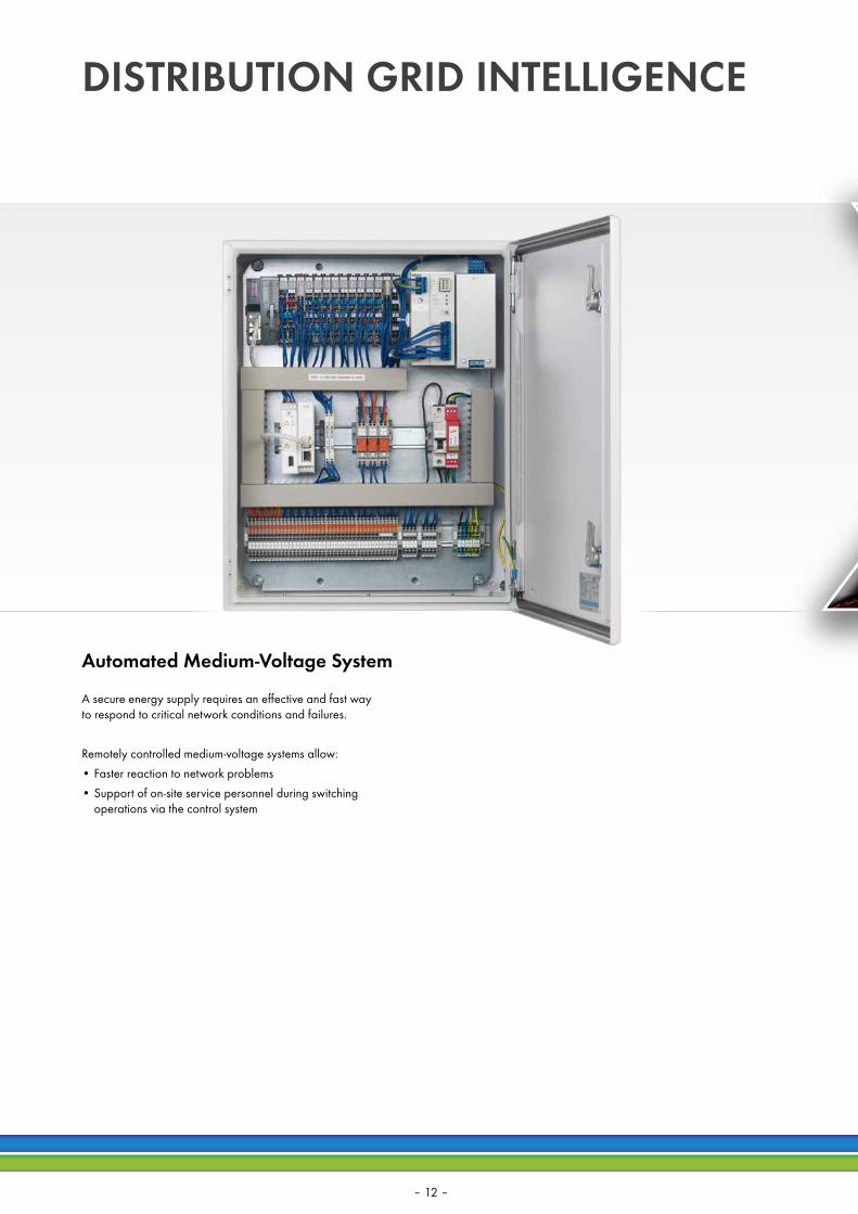
DISTRIBUTION GRID INTELLIGENCE
Automated Medium-Voltage System
A secure energy supply requires an effective and fast way to respond to critical network conditions and failures.
Remotely controlled medium-voltage systems allow:• Faster reaction to network problems• Support of on-site service personnel during switching
operations via the control system
– 12 –

Taking it to the eXTReme — The standard for 750 XTRWAGO-I/O-SYSTEM 750 XTR
• No air conditioning required• Compact footprint• Lower energy and maintenance costs
• Can be used in unshielded areas• Ideal for standard telecontrol equipment• Increased system uptime
• Install close to vibrating and shock- generating system components
• Increased system uptime• Investment security
DIN EN 60870-2-1 DIN EN 60068-2-6
eXTReme vibration up to 5g of acceleration
eXTReme isolation up to 5 kV of impulse voltage
eXTReme temperature from -40 °C to +70 °C
– 13 –

=≈
888 888
Power inverter
Control
PV modules
Stratified storage tank
Boiler
Grid
kWh
Domestic hot water
Heater
Heating element
Consumer
POWER TO HEATIntelligent Heat Storage Systems Fueled by Renewable Energy
Power-to-heat conversion is a technology used for load management. This technology absorbs temporary oversupply from wind and solar power and converts it into heat.It is particularly well suited to applications generating high amounts of heat (e.g., district heating grids).
• Connecting heat generator and accumulator via one control system
• Multiple interfaces — PROFIBUS, CAN, KNX, LON®, IEC 60870/61850/61400 and MODBUS
• OPC/XML client• Convenient measurement and monitoring of generator/
accumulator parameters (e.g., effective power, temperature and storage volume)
• Integration of current consumption forecasts and weather data• Programmable to IEC 61131• Communication via IEC 60870-5-101, -103/-104,
61400-25, 61850-7-420 telecontrol modules• Easy parameter setting via configurator• Scalable via 440+ I/O modules for diverse applications
(e.g., 3-phase power measurement module for network analysis)
Your advantages:
– 14 –

POWER TO GASModern Gas Storage Systems Managed by the WAGO-I/O-SYSTEM
Your advantages:
Requirements:
Using power-to-gas technology, electricity can be converted from renewable energy to hydrogen or synthetic natural gas and stored in the natural gas grid.
• Grid-connected integration of electrolyzers for storing large amounts of electricity
• Integration into the power distribution or transmission grid• Direct connection to an energy producer
(e.g., wind or solar farm)• Permanent monitoring and control of process parameters,
e.g., from pressure regulators and producer gas separators — including explosion-proof components
• Multiple interfaces — PROFIBUS, CAN, KNX, LON®, IEC 60870/61850/61400 and MODBUS
• Standard I/O modules and intrinsically safe Ex modules in one control unit*
• OPC/XML client• Programmable to IEC 61131• Communication via IEC 60870-5-101, -103/-104,
61400-25, 61850-7-420 telecontrol modules• Scalable via 440+ I/O modules for diverse applications
(e.g., 3-phase power measurement module for network analysis) *in explosion-proof (Ex) housing, based on the installation location
Zone 2Zone 22
Zone 20Zone 0
Hazardous area Non-hazardous area
WAGO-I/O-SYSTEM
Zone 21Zone 1
– 15 –
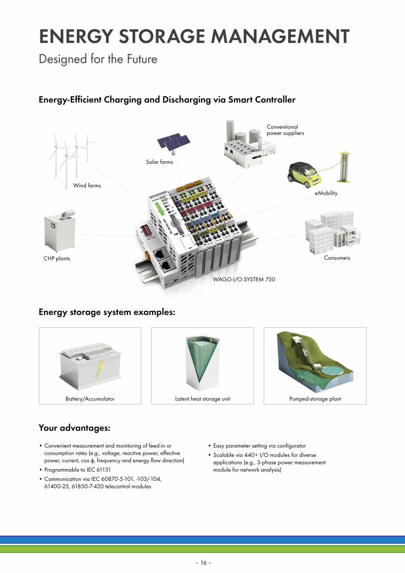
• Convenient measurement and monitoring of feed-in or consumption rates (e.g., voltage, reactive power, effective power, current, cos φ, frequency and energy flow direction)
• Programmable to IEC 61131• Communication via IEC 60870-5-101, -103/-104,
61400-25, 61850-7-420 telecontrol modules
• Easy parameter setting via configurator• Scalable via 440+ I/O modules for diverse
applications (e.g., 3-phase power measurement module for network analysis)
Your advantages:
Energy-Efficient Charging and Discharging via Smart Controller
CHP plants
WAGO-I/O-SYSTEM 750
Wind farms
Solar farms
Conventional power suppliers
eMobility
Consumers
Energy storage system examples:
Battery/Accumulator Latent heat storage unit Pumped-storage plant
ENERGY STORAGE MANAGEMENTDesigned for the Future
– 16 –

PROTECTION DEVICESIEC 61850 GOOSE / IEC 60870-5-103 Client
• Equipment connection, e.g., protection devices or power meters• Easily set communication parameters via CODESYS’
integrated configurator• Parameter files for protection devices can be read• Communication to the control system or data concentrator via
IEC 60870-5-101/-104, IEC 61850, MMS, PROFIBUS and MODBUS• Create gateways, e.g., for connecting to the network control system• Compatible with WAGO controllers in every performance class
Your advantages:
– 17 –

GAS DISTRIBUTION STATION
01
02
03
ETH
ERN
ET
Communication options, e.g., via IEC 60870-5-104
• Communication per IEC 60870-5-101, -103 /-104, 61400-25, 61850, MODBUS and others
• Redundant structures: The telecontroller communicates with up to four higher-level control systems
• Measure all variables — including signal acquisition from hazardous areas via Ex i I/O modules — without additional components for Ex separation, such as Zener barriers
• Certified to ATEX, IECEx, UL ANSI/ISA 12.12.01, UL508, shipbuilding, GOST-R and more
• The software PI controller implemented in the telecontroller replaces the separate industrial controller for gas pressure control
• DSFG protocol upon request
Unite Traditional Automation and Telecontrol Applications into One System
– 18 –
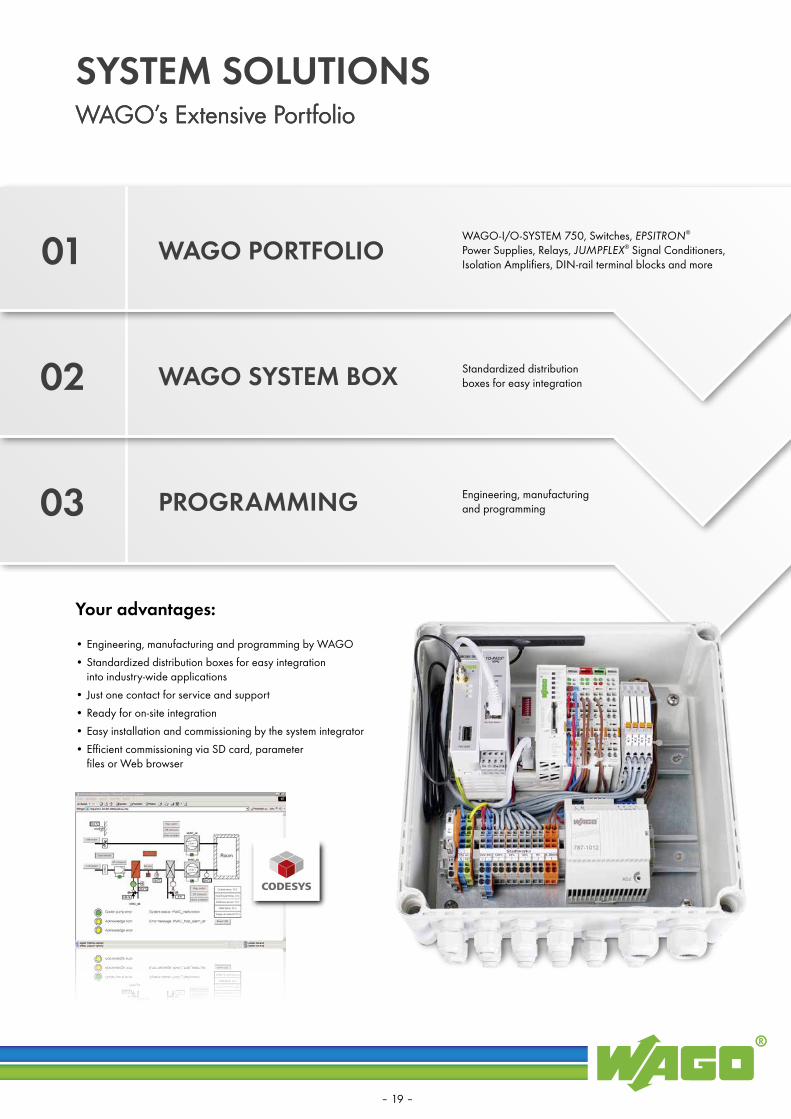
SYSTEM SOLUTIONS
01
02
03
WAGO’s Extensive Portfolio
WAGO PORTFOLIO
PROGRAMMING
WAGO SYSTEM BOX
• Engineering, manufacturing and programming by WAGO• Standardized distribution boxes for easy integration
into industry-wide applications• Just one contact for service and support• Ready for on-site integration• Easy installation and commissioning by the system integrator• Efficient commissioning via SD card, parameter
files or Web browser
WAGO-I/O-SYSTEM 750, Switches, EPSITRON® Power Supplies, Relays, JUMPFLEX® Signal Conditioners, Isolation Amplifiers, DIN-rail terminal blocks and more
Standardized distribution boxes for easy integration
Engineering, manufacturing and programming
Your advantages:
WAGO’s Extensive Portfolio
– 19 –

Cont
rol l
evel
Tran
smiss
ion
leve
lFi
eld
leve
l
Transmission per IEC 60870-5-104
via IPSec VPN tunnel
GSM Modem connection
1−16 telecontrol substations with a modem connection
1−64 telecontrol substations
Transmission per IEC 60870-5-101/-103/-104
Transmission per IEC 60870-5-101/-103/-104
WAGO Telecontrol Gateway per IEC 60870-5-104 and IEC 60870-5-101
WAGO Telecontrol Gateway “light” for up to 16 substations
Configuration:
Router with fixed IP
Web-Based Management
• Communication per IEC 60870-5-101/-103/-104• Connect to a substation via GSM, dedicated or dial-up line• No control system limiting the number of connections• Easy parameterization via Web-based management• Transmitted data requires no parameterization• Optional redundancy
TELECONTROL GATEWAY
Your advantages:
Manufacturer-Independent Connection of Telecontrol Substations with up to Two Redundant Control Systems
– 20 –

SNMP GOES IEC 60870/61850
• Integration of PCs, switches, modems, UPS systems via SNMP protocol
• Transmission of status information to the control system• Device information can be read via GET command
and transformed into IEC variables• IEC variables permit device control via SET command • Flexible parameterization via editable CSV file on SD card• Pre-configured files are available for select components• Additional device types can be integrated
via Management Information Base (MIB)
Connecting Network Components with the Control System
– 21 –

WAGO-I/O-SYSTEM 750One System for Every Application
Fieldbus Couplers Programmable Fieldbus Controllers
• Fieldbus couplers connect the WAGO-I/O-SYSTEM 750 to a higher-level control system
• Fieldbus-independent — Support all standard fieldbus protocols and ETHERNET standards
• Space-saving design
• Controllers for all standard fieldbus systems and ETHERNET standards
• Quick start-up• Programmable via CODESYS per IEC 61131-3• Direct connection to a wide range of I/O modules
within the WAGO-I/O-SYSTEM 750• Flexible platform adapts to diverse applications
and environments
– 22 –

PFC200 Controllers WAGO-I/O-PRO Software
• Robust and maintenance-free• Scalable performance• Controllers for all standard fieldbus systems
and ETHERNET standards• High processing speed• Multiple communication interfaces can be used simultaneously• Separate ETHERNET interfaces permit the creation
of parallel networks
• The Linux® operating system allows you to create your own firmware (Linux® developers only)
• Programmable via CODESYS per IEC 61131-3• Can be combined with high-level languages• Linux® 3.6 real-time operating system• The Linux® platform enables the creation of “Custom Images”• Flexibility for the implementation of IT security requirements• SSH and SSL provide high levels of security• Password-protected Web-based management prevents
unauthorized users from changing system settings
IEC 60870-5-101-/-103-/-104 Client/ServerIEC 61850 Client/Server
IEC 61400-25
– 23 –

Communication via telecontrol protocols per IEC 60870-5-101 /-103 /-104, 61400-25, 61850, MODBUS
3-Phase Power Measurement Module for network analysis (current, voltage, reactive power, effective power, frequency and energy flow direction), as well as comparative cos ϕ measurement
Connection is possible via DSL, GSM, ISDN, fiber optic, analog or radio
Additional programming options that adhere to IEC 61131
Easy parameterization via Web visualization
• Expansion via 440+ I/O modules for many applications• Integration of specialty functions, e.g., reactive power/
undervoltage protection via I/O modules
WAGO-I/O-SYSTEM 750Advantages
– 24 –

Reading the hardware setup via WAGO-I/O-CHECK
Setting parameters for a telecontrol substation
Linking the plain text variables to the type message
Optional: Assigning plain text variables
Defining the type message
Creating the CODESYS source code automatically
CONNECTING TO A TELECONTROL SYSTEMWAGO-I/O-SYSTEM 750Fast Commissioning via IEC Configurator
– 25 –

CONFIGURINGWAGO-I/O-SYSTEM 750 Configuration
• Configuration instead of programming• Signal-oriented IEC 60870• Object-oriented IEC 61850• Modbus TCP/RTU
• Part of WAGO-I/O-PRO v2.3 software• Supports IEC 60870-5-101 (Client/Server/-103
(Client)/-104(Client/Server) specific functions • Configures and parameterizes both IEC 60870 objects
and data exchange to the PLC application or I/O modules• Import and export functions in CSV and XML formats
permit transmission to engineering tools• Sets protocol gateways
• Part of WAGO-I/O-PRO v2.3 software • Supports IEC 61850 (Client/Server) specific functions • MMS communication • GOOSE publisher and subscriber• Configures and parameterizes both IEC 61850 objects
and data exchange to the PLC application or I/O modules• Sets protocol gateways (e.g., IEC 60870) • Import and export functions in the IEC 61850 SCL exchange
format enable transmission to engineering tools
IEC 60870 Configurator IEC 61850 Configurator
Your advantages:
– 26 –

• Expedited commissioning• Parameterization via Web browser• CODESYS 2 WebVisu can be accessed on mobile devices
PARAMETER SETTINGParameter Setting Instead of Programming
Your advantages:
– 27 –

PROGRAMMINGControllers: Open — Flexible — Compact
• Programmable via CODESYS per IEC 61131-3• Can be combined with C/C++ high-level languages• Linux® 3.6 real-time operating system• Robust and maintenance-free• SSH and SSL provide high levels of security
• Programming and visualization tool based on CODESYS that adheres to IEC 61131-3
• Supports the following standard programming languages: IL, SFC, LD, FBD and ST
• Open interfaces (OPC, DDE) enable data exchange with other programs
• Highly efficient translation between programming languages• Automatic declaration of variables• Library management• Online status indication in the program code• Offline simulation and integrated process visualization• Recording and graphical display of project variables
Your advantages: WAGO-I/O-PRO Software
– 28 –
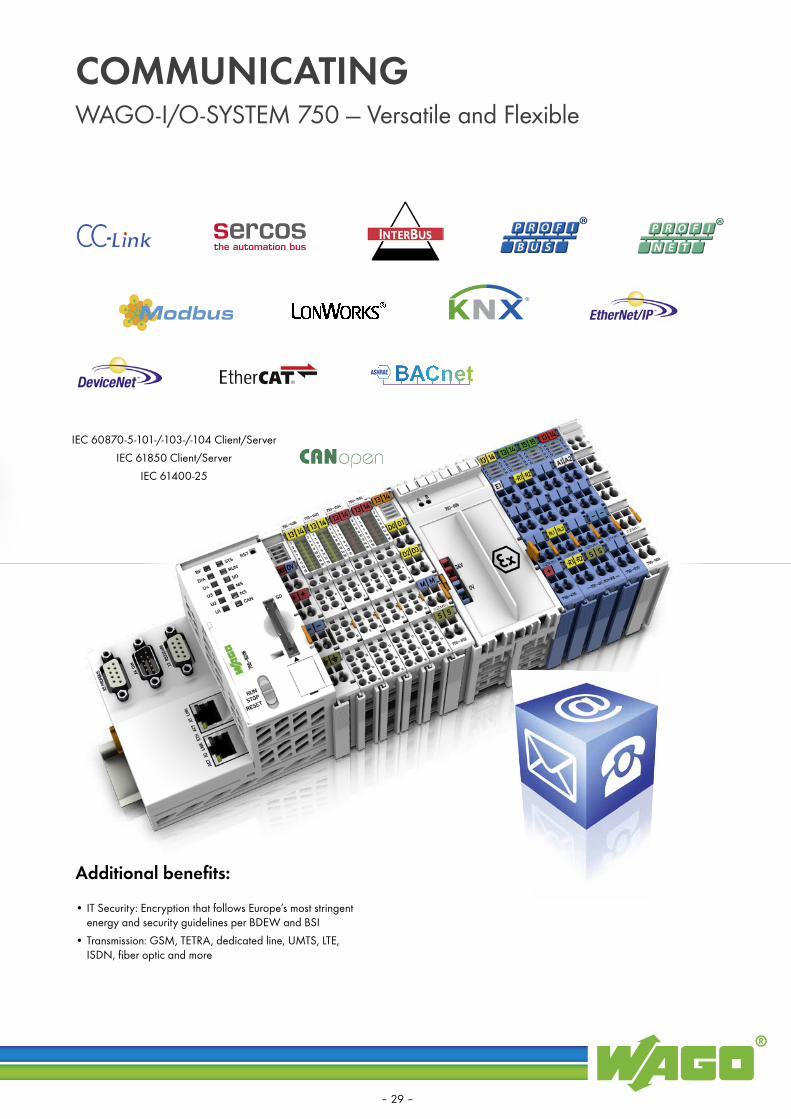
COMMUNICATINGWAGO-I/O-SYSTEM 750 — Versatile and Flexible
• IT Security: Encryption that follows Europe’s most stringent energy and security guidelines per BDEW and BSI
• Transmission: GSM, TETRA, dedicated line, UMTS, LTE, ISDN, fiber optic and more
Additional benefits:
IEC 60870-5-101-/-103-/-104 Client/ServerIEC 61850 Client/Server
IEC 61400-25
– 29 –

TO-PASS® TELECONTROL SOLUTIONSScalable Telecontrol Solutions
TO-PASS® Outdoor
TO-PASS® Compact
TO-PASS® Mobile
– 30 –

Fault Detection and Monitoring
TO-PASS® Compact • Convenient, compact solution with integrated GSM
modem and inputs/outputs• Message dispatch via SMS, email, fax or over the phone• Up to eight analog and digital inputs• Four digital and analog outputs• Acknowledgment: Any fault message• Stand-by: Automatic remote switching of stand-by service• Remote parameterization: Conveniently perform programming
and process visualization from the office• GPRS-dedicated line: Permanent online connection to the
process from a Web server or PC with a fixed IP address (e.g., DSL connection)
• Event logger: Saves all occurring status changes• Data logger: Saves all process values with an adjustable cycle• MODBUS: Reading from 64 MODBUS 2-byte
registers via serial interface• Counter function: Maximum of four digital
inputs can be used as an up or down counter; the maximum operating frequency is 1250 Hz
TO-PASS® Mobile• Compact module with an integrated GPS receiver,
GSM modem and inputs/outputs for direct mounting• Acquisition of measured values and position data• Email, SMS (bidirectional), fax (depending on provider)
and dial-up connection (CSD)• Internal memory for GPS and process data• GPS receiver• GPS raw data• Map view via Google Maps and Open Street Map• Waypoints and distance
TO-PASS® Web PortalBase moduleWith the base module, users receive a dedicated space on the TO-PASS® Web portal. Access is protected with a user- name and password. The data recorder function allows digital, analog and MODBUS data from connected devices to be recorded and displayed in segments ranging from 90 minutes to 512 days. Data can also be exported in the CSV format. AdminThis option is an addition to the base module. It allows the user to administrate additional usernames with passwords, as well as customers and devices with different access authorizations.AlarmThis is an optional function for the base module. It allows the module to display and administer alarms. Using analog values, up to four limit values can be configured for each measurement. An alarm list allows all alarms to be displayed and acknowledged. This option also allows the user to designate the recipients and the times when they will receive an alarm via SMS or email.
TO-PASS® Outdoor All-In-One Solution• Compact, IP66 enclosure for installing TO-PASS® telecontrol
modules. The unit is equipped with an integrated GSM antenna and a 115–230 VAC to 24 VDC power supply.
• Two backup batteries protect against power failure and supply additional sensors
• All-in-one solution eliminates wiring costs• Antenna is hidden inside the enclosure• Fast outdoor installation• Battery provides power failure protection• Built-in heating system for operation in temperatures < -20 °C• Also available with self-sustaining solar operation
– 31 –
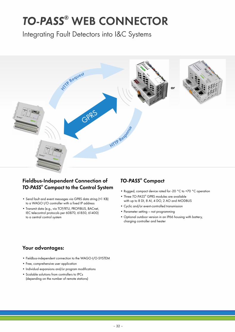
TO-PASS® WEB CONNECTORIntegrating Fault Detectors into I&C Systems
• Send fault and event messages via GPRS data string (<1 KB) to a WAGO I/O controller with a fixed IP address
• Transmit data (e.g., via TCP/RTU, PROFIBUS, BACnet, IEC telecontrol protocols per 60870, 61850, 61400) to a central control system
• Rugged, compact device rated for -20 °C to +70 °C operation• Three TO-PASS® GPRS modules are available
with up to 8 DI, 8 AI, 4 DO, 2 AO and MODBUS• Cyclic and/or event-controlled transmission• Parameter setting — not programming• Optional outdoor version in an IP66 housing with battery,
charging controller and heater
• Fieldbus-independent connection to the WAGO-I/O-SYSTEM• Free, comprehensive user application• Individual expansions and/or program modifications• Scalable solutions from controllers to IPCs
(depending on the number of remote stations)
or
GPRS
Your advantages:
Fieldbus-Independent Connection of TO-PASS® Compact to the Control System
TO-PASS® Compact
HTT
P Request
HTTP Respon
se
– 32 –

Error
Quit
30 %
Y = 100 %
0 %0 %
Status messagesCollective malfunction:Pre-�ush:Air damper:
OKPre�ushing completedOpen
Exhaust air damper: Open
Supply air (HE)Exhaust air (HE)Incoming air fan:Exhaust air fan:
ONONOKOK
Overriding sensor values
Manual
Error
Quit
Y = 79.4 %
Y = 100.0 %
Y = 100.0 %
18.0°C
12.0°C
31.0°C
15.0°C
18.0°C22.0°C
1800 mBar
100 % 0 %
2000 mBar
18.0°C28.0°C
100 %100 %
Con�gurationHome page
SYSTEM MACROSHeating, Ventilation and Air Conditioning
• Suitable for a wide range of HVAC applications (e.g., heat transfer station)
• No time-consuming programming• Individual adjustment via parameter settings
Switching ventilation system on/off
Determining the setpoint supply temperature for the boiler system based on the outside temperature
Air-side antifreeze protection via antifreeze monitor installed in the system
Controlling the outside air dampers (one function block per damper)
*HR = Heat recovery*Supply Temp = Supply temperature
Pump HR* PID controller Fan
DampersAntifreeze protectionStart Supply Temp*Enable
Parameter Setting — Not Programming
– 33 –
r n g 0 / 4p i .
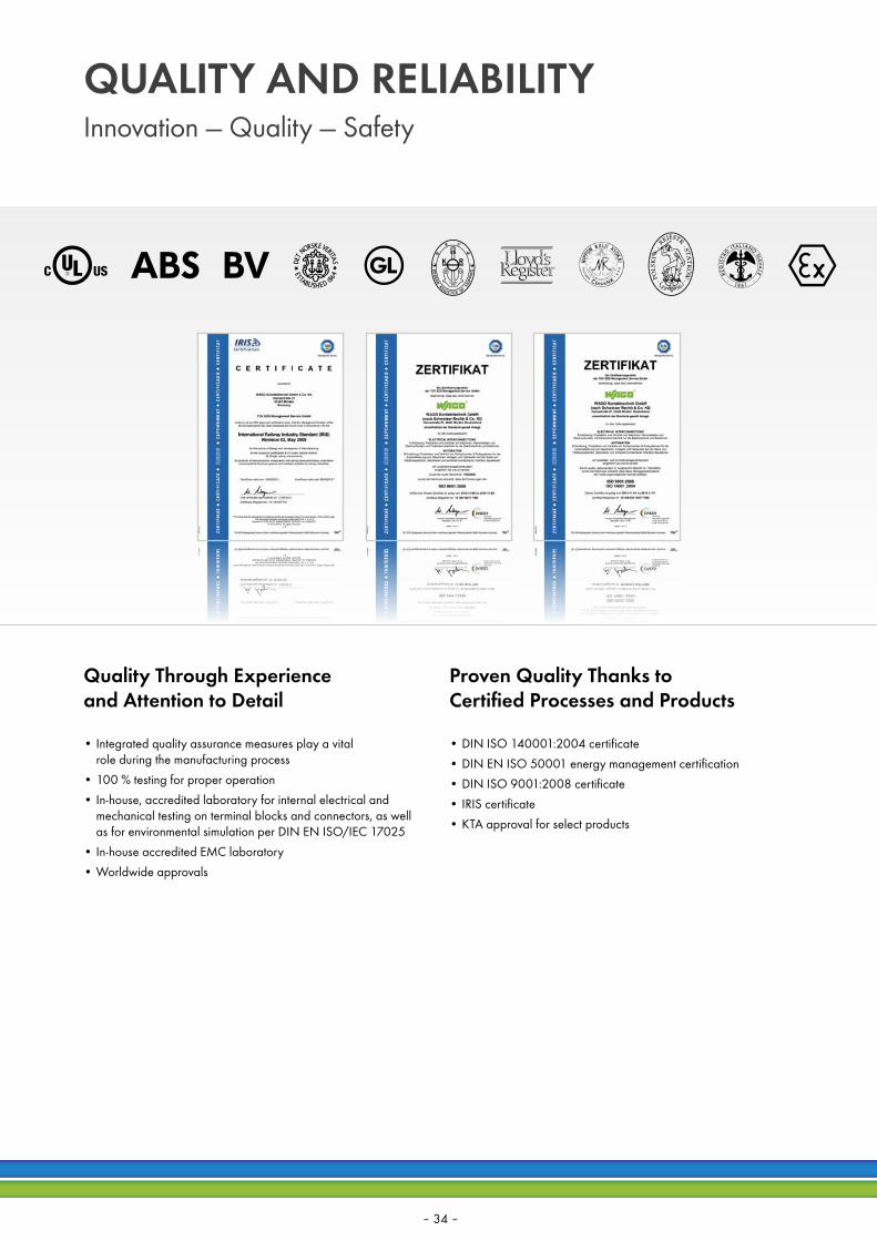
QUALITY AND RELIABILITYInnovation — Quality — Safety
• Integrated quality assurance measures play a vital role during the manufacturing process
• 100 % testing for proper operation• In-house, accredited laboratory for internal electrical and
mechanical testing on terminal blocks and connectors, as well as for environmental simulation per DIN EN ISO/IEC 17025
• In-house accredited EMC laboratory• Worldwide approvals
Quality Through Experience and Attention to Detail
Proven Quality Thanks to Certified Processes and Products
• DIN ISO 140001:2004 certificate• DIN EN ISO 50001 energy management certification• DIN ISO 9001:2008 certificate• IRIS certificate• KTA approval for select products
– 34 –

Das WaGO-I/O-sYsTEM 750Das System für alle Anwendungen
TAKING IT TO THE EXTREME —
THE STANDARD FOR 750 XTR
WAGO-I/O-SYSTEM 750750 XTR Series
STROM- UND ENERGIEMESSTECHNIK
Full Line Catalog, Volume 1Edition: 2015
Rail-Mounted Terminal Block Systems
Full Line Catalog, Volume 3Edition: 2015
Automation Technology
WINSTA®
The Pluggable Connection System
Full Line Catalog, Volume 5Edition: 2015
PCB Terminal Blocks and Connectors
Full Line Catalog, Volume 2Edition: 2015
Full Line Catalog, Volume 4Edition: 2015
Interface Electronic
WAGO CATALOGS/BROCHURESWAGO-I/O-SYSTEM 750 — Versatile and Flexible
• Rail-Mounted Terminal Blocks• Modular Connectors (X-COM®-
SYSTEM and X-COM®S-SYSTEM)• Patchboard Systems• Terminal Strips• PUSH WIRE® Connectors
for Junction Boxes• Lighting Connectors• Shield Connecting System
• IP20 Modular I/O-SYSTEM• Radio Technology, TO-PASS®
Telecontrol Technology• Industrial Switches, PERSPECTO®
• IP67 Modular I/O-SYSTEM, IP67 Block I/O-SYSTEM
• IP67 Sensor/Actuator Boxes, IP67 Cables and Connectors
• Power Supplies
• WINSTA® MINI — Pluggable Connectors• WINSTA® MINI special — Pluggable Connectors• WINSTA® MIDI — Pluggable Connectors• WINSTA® MIDI special — Pluggable Connectors• WINSTA® MAXI — Pluggable Connectors• WINSTA® RD — Cable Assemblies• WINSTA® KNX — Pluggable Connectors• WINSTA® IDC — Flat Cable Systems
• PCB Terminal Blocks• Feedthrough Terminal Blocks• MULTI CONNECTION SYSTEM (MCS)• Pluggable PCB Terminal Blocks• Specialty Connectors
• Relays – Optocouplers – Specialty Functions
• Interface Modules• Signal Conditioners• Power Supplies• Overvoltage Protection• Radio Technology• Empty Housings and
DIN-Rail Mount Carriers
Volume 1, Rail-Mounted Terminal Block Systems
Volume 3, AUTOMATION
Volume 5, WINSTA® — The Pluggable Connection System
WAGO-I/O-SYSTEM 750, 750 XTR Series
Current and Energy Measurement Technology
WAGO-I/O-SYSTEM 750
THE WAGO-I/O-SYSTEM 750One System for Every Application
CURRENT AND ENERGY MEASUREMENT TECHNOLOGY
Volume 2, PCB Terminal Blocks and Connectors
Volume 4, INTERFACE ELECTRONIC
– 35 –

5131
0462
- 08
88-0
590/
0200
-690
1 - B
RAN
CH
BRO
CH
URE
TEL
ECO
NTR
OL 2
.0 U
S - 0
2/15
_01
- Prin
ted
in G
erm
any
- Sub
ject
to d
esig
n ch
ange
s
WAGO Kontakttechnik GmbH & Co. KGPostfach 28 80 · D - 32385 MindenHansastraße 27 · D - 32423 MindenGermanyPhone: +49 571 887- 0Fax: +49 571 887-169Email: [email protected]: www.wago.com


