16
TC450 SERIES TELESCOPIC CRANE
2
CONTENTS / / / / / / / / / / / / / / / / / / / / / / / / / / / / / / / / / / / / / / / / / / / / / / / / / / / / / / / / / / / / / / / / / / / / / / / / / / / / / / / / / / / / / / / /Crane Features ................................................................................................................................................................................4Chassis Data ................................................................................................................................................................................... 5Outrigger Extension......................................................................................................................................................................... 6Sub Frame ........................................................................................................................................................................................6Electrical System..............................................................................................................................................................................6Intermediate Spread ....................................................................................................................................................................... 7Fully Retracted Spread ................................................................................................................................................................... 7TC450 Load Chart: Main Boom ........................................................................................................................................................8TC450 Boom Diagram .....................................................................................................................................................................9TC450 Load Chart: Jib ....................................................................................................................................................................10Reeving Diagram ........................................................................................................................................................................... 11Area of Operation...........................................................................................................................................................................12LMI Codes .................................................................................................................................................................................... 12Warning, Information & Definitions ............................................................................................................................................. 13Technical Descriptions ................................................................................................................................................................. 14Options ......................................................................................................................................................................................... 15
Effective Date: September 1, 2015This document is non-contractual. This document is supplied for reference use only. We are constantly making improvements to our products and reserve the right that specification, equipment, and prices are all subject to change without notice or obligation. The photographs, and /or images in this document are for illustrative purposes only and may include optional equipment and accessories and may not include all standard equipment. Refer to the appropriate Operator’s Manual and Load Charts for instructions on the proper use of this equipment to determine allowable crane lifting capacities, assembly and operating procedures.Failure to follow the appropriate operator’s manual or load chart(s) when using our equipment or to otherwise act irresponsibly may result in serious injury or death. The only warranty applicable to our equipment is the standard written warranty applicable to the particular product and sale. Manitex makes no other warranty, expressed or implied. Products and services listed may be trademarks, service marks or trade-names of Manitex International and /or its subsidiaries in the USA and other countries. All rights are reserved. Manitex® is a registered trademark of Manitex International, Inc. in the USA and many other countries.Copyright 2013 Manitex Inc. Manitex Inc, Georgetown Texas, 78626
3
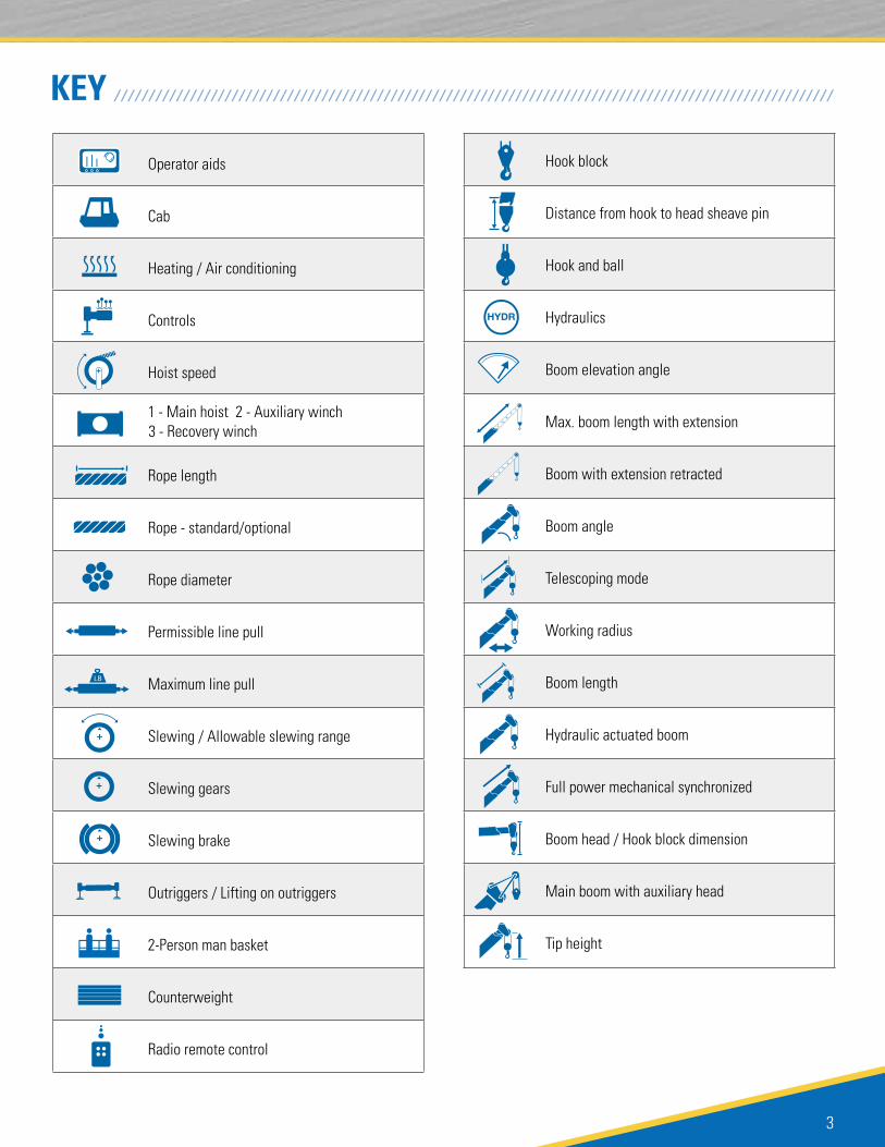
KEY / / / / / / / / / / / / / / / / / / / / / / / / / / / / / / / / / / / / / / / / / / / / / / / / / / / / / / / / / / / / / / / / / / / / / / / / / / / / / / / / / / / / / / / / / / / / / / / / / / / / / / / /
Operator aids
Cab
Heating / Air conditioning
Controls
Hoist speed
1 - Main hoist 2 - Auxiliary winch 3 - Recovery winch
Rope length
Rope - standard/optional
Rope diameter
Permissible line pull
Maximum line pull
Slewing / Allowable slewing range
Slewing gears
Slewing brake
Outriggers / Lifting on outriggers
2-Person man basket
Counterweight
Radio remote control
Hook block
Distance from hook to head sheave pin
Hook and ball
Hydraulics
Boom elevation angle
Max. boom length with extension
Boom with extension retracted
Boom angle
Telescoping mode
Working radius
Boom length
Hydraulic actuated boom
Full power mechanical synchronized
Boom head / Hook block dimension
Main boom with auxiliary head
Tip height
TC450 SERIES TELESCOPIC CRANE
4
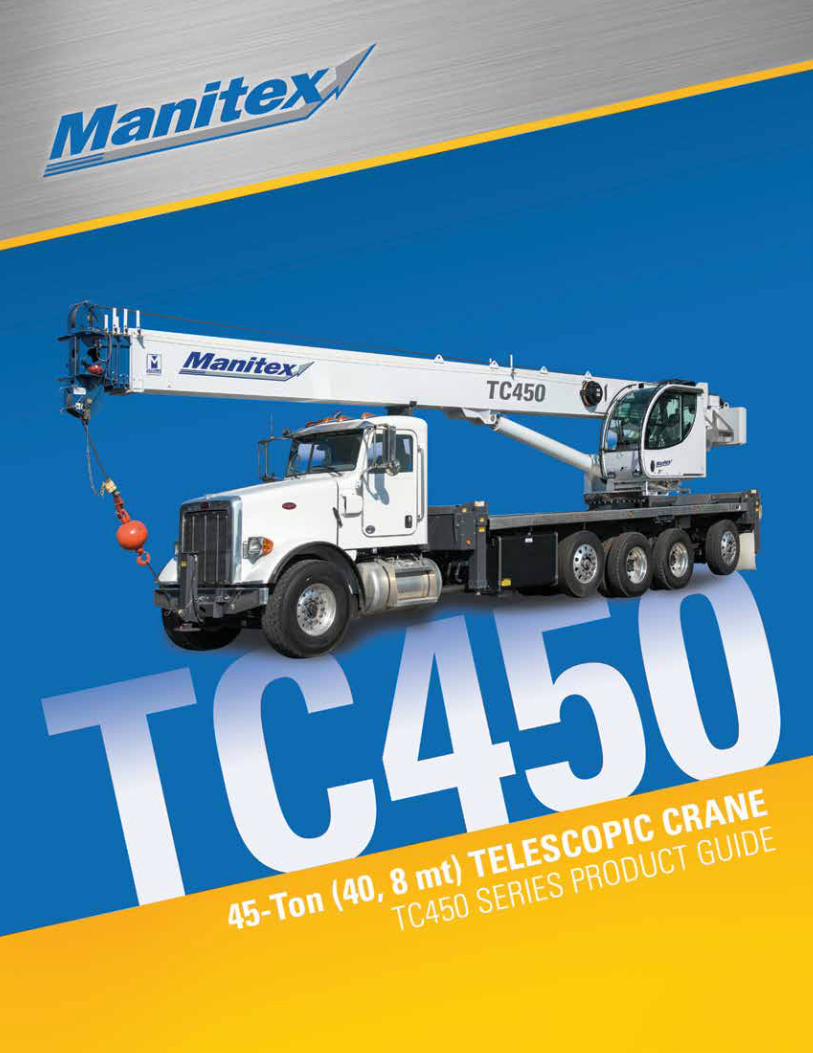
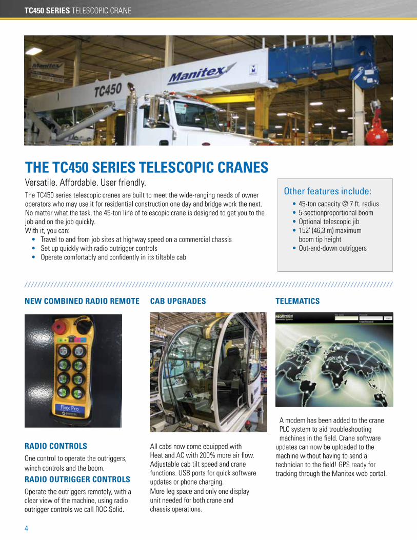
THE TC450 SERIES TELESCOPIC CRANESVersatile. Affordable. User friendly.The TC450 series telescopic cranes are built to meet the wide-ranging needs of owner operators who may use it for residential construction one day and bridge work the next. No matter what the task, the 45-ton line of telescopic crane is designed to get you to the job and on the job quickly. With it, you can: • Travel to and from job sites at highway speed on a commercial chassis • Set up quickly with radio outrigger controls • Operate comfortably and confidently in its tiltable cab
Other features include: • 45-ton capacity @ 7 ft. radius • 5-sectionproportional boom • Optional telescopic jib • 152' (46,3 m) maximum boom tip height • Out-and-down outriggers
TELEMATICS
/ / / / / / / / / / / / / / / / / / / / / / / / / / / / / / / / / / / / / / / / / / / / / / / / / / / / / / / / / / / / / / / / / / / / / / / / / / / / / / / / / / / / / / / / / / / / / / / / / / / / / / / / / / / / / / / / /
A modem has been added to the crane PLC system to aid troubleshooting machines in the field. Crane software
updates can now be uploaded to the machine without having to send a technician to the field! GPS ready for tracking through the Manitex web portal.
NEW COMBINED RADIO REMOTE
RADIO CONTROLSOne control to operate the outriggers, winch controls and the boom.
RADIO OUTRIGGER CONTROLSOperate the outriggers remotely, with a clear view of the machine, using radio outrigger controls we call ROC Solid.
CAB UPGRADES
All cabs now come equipped with Heat and AC with 200% more air flow. Adjustable cab tilt speed and crane functions. USB ports for quick software updates or phone charging.More leg space and only one display unit needed for both crane and chassis operations.
5
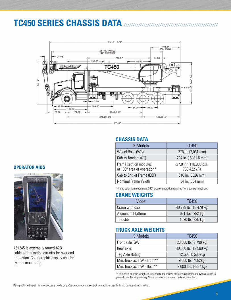
OPERATOR AIDS
45124S is externally routed A2B cable with function cut-offs for overload protection. Color graphic display unit for system monitoring.
TC450 SERIES CHASSIS DATA / / / / / / / / / / / / / / / / / / / / / / / / / / / / / / / / / / / / / / / / / / / / / / / / / / / /
Data published herein is intended as a guide only. Crane operation is subject to machine specific load charts and information.
CRANE WEIGHTS
TRUCK AXLE WEIGHTS
CHASSIS DATA
S Models TC450Front axle (GW) 20,000 lb. (9,790 kg)Rear axle 40,000 lb. (19,580 kg)Tag Axle Rating 12,500 lb 5669kgMin. truck axle W - Front** 9,000 lb. (4082kg)Min. truck axle W - Rear** 9,600 lbs. (4354 kg)
S Models TC450Wheel Base (WB) 278 in. (7,061 mm)Cab to Tandem (CT) 204 in. ( 5281.6 mm)
Frame section modulus at 180º area of operation*
27.0 in3, 110,000 psi, 758,422 kPa
Cab to End of Frame (EOF) 316 in. (8026 mm)Nominal Frame Width 34 in. (864 mm)
Model TC450Crane with cab 40,738 lb. (18,479 kg)Aluminum Platform 621 lbs. (282 kg)Tele Jib 1620 lb. (735 kg)
* Frame selection modulus at 360º area of operation requires front bumper stabilizer.
** Minimum chassis weight is required to meet 85% stability requirements. Chassis data is general - not for engineering. Some dimensions depend on truck selection.
TC450 SERIES TELESCOPIC CRANE
6
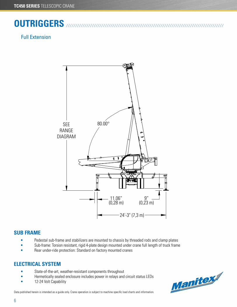
OUTRIGGERS / / / / / / / / / / / / / / / / / / / / / / / / / / / / / / / / / / / / / / / / / / / / / / / / / / / / / / / / / / / / / / / / / / / / / / / / / / / / / / / / / / / / /
Data published herein is intended as a guide only. Crane operation is subject to machine specific load charts and information.
Full Extension
ELECTRICAL SYSTEM
SUB FRAME
• State-of-the-art, weather-resistant components throughout• Hermetically sealed enclosure includes power in relays and circuit status LEDs• 12-24 Volt Capability
• Pedestal sub-frame and stabilizers are mounted to chassis by threaded rods and clamp plates• Sub-frame: Torsion resistant, rigid 4-plate design mounted under crane full length of truck frame• Rear under-ride protection: Standard on factory mounted cranes
7
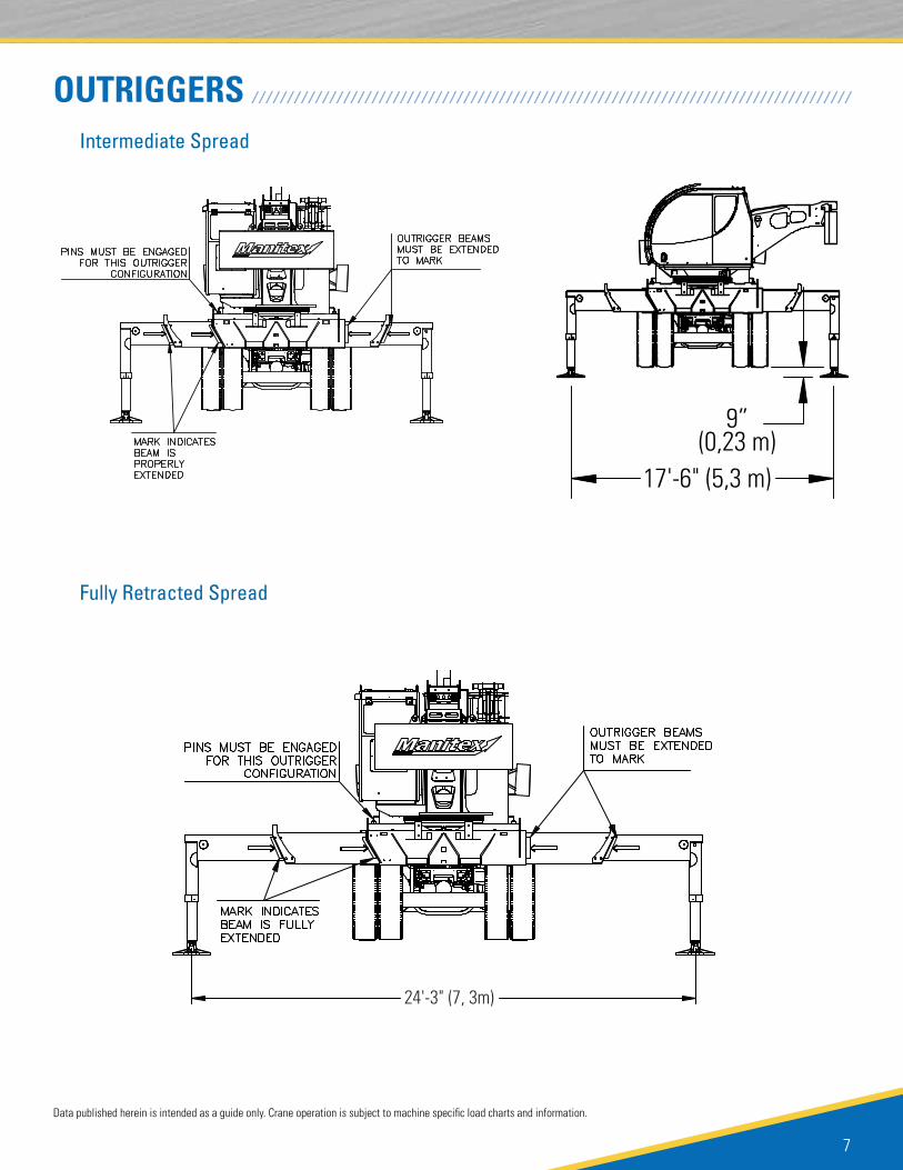
OUTRIGGERS / / / / / / / / / / / / / / / / / / / / / / / / / / / / / / / / / / / / / / / / / / / / / / / / / / / / / / / / / / / / / / / / / / / / / / / / / / / / / / / / / / / / /Intermediate Spread
Fully Retracted Spread
24'-3" (7, 3m)
Data published herein is intended as a guide only. Crane operation is subject to machine specific load charts and information.
TC450 SERIES TELESCOPIC CRANE
8
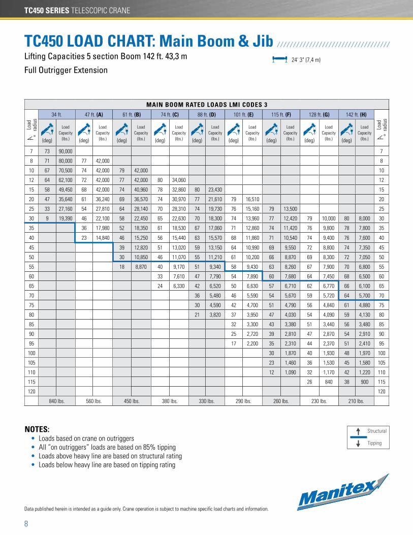
Lifting Capacities 5 section Boom 142 ft. 43,3 m
Full Outrigger Extension
TC450 LOAD CHART: Main Boom & Jib / / / / / / / / / / / / / / / / / / / / / / / / / / / / / / / / / / /
NOTES: • Loads based on crane on outriggers • All “on outriggers” loads are based on 85% tipping • Loads above heavy line are based on structural rating • Loads below heavy line are based on tipping rating
Data published herein is intended as a guide only. Crane operation is subject to machine specific load charts and information.
24' 3" (7,4 m)
MAIN BOOM RATED LOADS LMI CODES 3
Load
ra
dius
°
34 ft. 47 ft. (A) 61 ft. (B) 74 ft. (C) 88 ft. (D) 101 ft. (E) 115 ft. (F) 128 ft. (G) 142 ft. (H)
Load
ra
dius
°(deg)
Load Capacity
(lbs.) (deg)
Load Capacity
(lbs.) (deg)
Load Capacity
(lbs.) (deg)
Load Capacity
(lbs.) (deg)
Load Capacity
(lbs.) (deg)
Load Capacity
(lbs.) (deg)
Load Capacity
(lbs.) (deg)
Load Capacity
(lbs.) (deg)
Load Capacity
(lbs.)
7 73 90,000 7
8 71 80,000 77 42,000 8
10 67 70,500 74 42,000 79 42,000 10
12 64 62,100 72 42,000 77 42,000 80 34,060 12
15 58 49,450 68 42,000 74 40,960 78 32,860 80 23,430 15
20 47 35,640 61 36,240 69 36,570 74 30,970 77 21,610 79 16,510 20
25 33 27,160 54 27,810 64 28,140 70 28,310 74 19,730 76 15,160 79 13,500 25
30 9 19,390 46 22,100 58 22,450 65 22,630 70 18,300 74 13,960 77 12,420 79 10,000 80 8,000 30
35 36 17,980 52 18,350 61 18,530 67 17,060 71 12,860 74 11,420 76 9,800 78 7,800 35
40 23 14,840 46 15,250 56 15,440 63 15,570 68 11,860 71 10,540 74 9,400 76 7,600 40
45 39 12,820 51 13,020 59 13,150 64 10,990 69 9,550 72 8,800 74 7,350 45
50 30 10,850 46 11,070 55 11,210 61 10,200 66 8,870 69 8,300 72 7,050 50
55 18 8,870 40 9,170 51 9,340 58 9,430 63 8,260 67 7,900 70 6,800 55
60 33 7,610 47 7,790 54 7,890 60 7,680 64 7,450 68 6,500 60
65 24 6,330 42 6,520 50 6,630 57 6,710 62 6,770 66 6,100 65
70 36 5,480 46 5,590 54 5,670 59 5,720 64 5,700 70
75 30 4,590 42 4,700 51 4,790 56 4,840 61 4,880 75
80 21 3,820 37 3,950 47 4,030 54 4,090 59 4,130 80
85 32 3,300 43 3,380 51 3,440 56 3,480 85
90 25 2,720 39 2,810 47 2,870 54 2,910 90
95 17 2,200 35 2,310 44 2,370 51 2,410 95
100 30 1,870 40 1,930 48 1,970 100
105 23 1,460 36 1,530 45 1,580 105
110 12 1,090 32 1,170 42 1,220 110
115 26 840 38 900 115
120 120
840 lbs. 560 lbs. 450 lbs. 380 lbs. 330 lbs. 290 lbs. 260 lbs. 230 lbs. 210 lbs.
Structural
Tipping
9
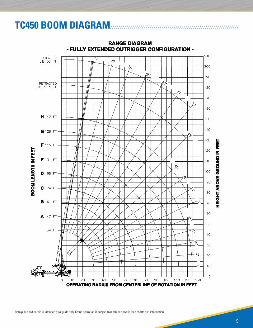
TC450 BOOM DIAGRAM/ / / / / / / / / / / / / / / / / / / / / / / / / / / / / / / / / / / / / / / / / / / / / / / / / / / / / / / / / / / / / / / / /
Data published herein is intended as a guide only. Crane operation is subject to machine specific load charts and information.
TC450 SERIES TELESCOPIC CRANE
10
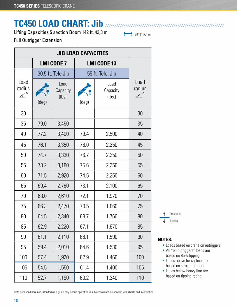
Lifting Capacities 5 section Boom 142 ft. 43,3 m
Full Outrigger Extension
TC450 LOAD CHART: Jib / / / / / / / / / / / / / / / / / / / / / / / / / / / / / / / / / / / / / / / / / / / / / / / / / / / / / / / / / / / / / / / /
NOTES: • Loads based on crane on outriggers • All “on outriggers” loads are based on 85% tipping • Loads above heavy line are based on structural rating • Loads below heavy line are based on tipping rating
24' 3" (7,4 m)
JIB LOAD CAPACITIES
LMI CODE 7 LMI CODE 13
Loadradius
°
30.5 ft. Tele Jib 55 ft. Tele. Jib
Loadradius
°(deg)
Load Capacity
(lbs.)(deg)
Load Capacity
(lbs.)
30 30
35 79.0 3,450 35
40 77.2 3,400 79.4 2,500 40
45 76.1 3,350 78.0 2,250 45
50 74.7 3,330 76.7 2,250 50
55 73.2 3,180 75.6 2,250 55
60 71.5 2,920 74.5 2,250 60
65 69.4 2,760 73.1 2,100 65
70 68.0 2,610 72.1 1,970 70
75 66.3 2,470 70.5 1,860 75
80 64.5 2,340 68.7 1,760 80
85 62.9 2,220 67.1 1,670 85
90 61.1 2,110 66.1 1,590 90
95 59.4 2,010 64.6 1,530 95
100 57.4 1,920 62.9 1,460 100
105 54.5 1,550 61.4 1,400 105
110 52.7 1,190 60.2 1,340 110
Data published herein is intended as a guide only. Crane operation is subject to machine specific load charts and information.
Structural
Tipping
11
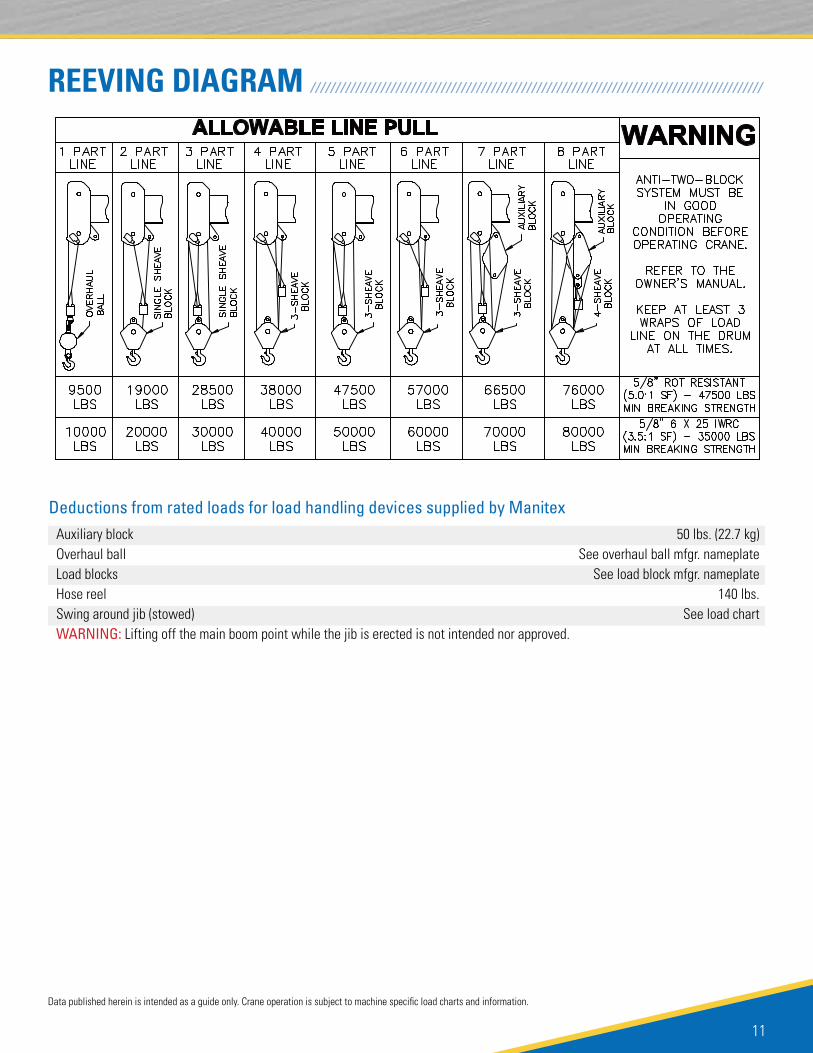
Deductions from rated loads for load handling devices supplied by Manitex
REEVING DIAGRAM / / / / / / / / / / / / / / / / / / / / / / / / / / / / / / / / / / / / / / / / / / / / / / / / / / / / / / / / / / / / / / / / / / / / / / / / / / / / / / / / / / / / / / / / / /
Auxiliary block 50 lbs. (22.7 kg) Overhaul ball See overhaul ball mfgr. nameplate Load blocks See load block mfgr. nameplate Hose reel 140 lbs. Swing around jib (stowed) See load chartWARNING: Lifting off the main boom point while the jib is erected is not intended nor approved.
Data published herein is intended as a guide only. Crane operation is subject to machine specific load charts and information.
TC450 SERIES TELESCOPIC CRANE
12
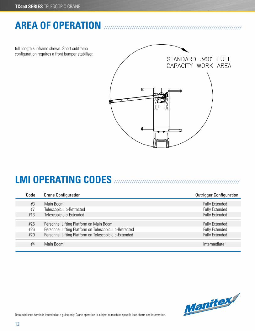
LMI OPERATING CODES / / / / / / / / / / / / / / / / / / / / / / / / / / / / / / / / / / / / / / / / / / / / / / / / / / / / / / / / / / / / / / /Code Crane Configuration Outrigger Configuration
#3 Main Boom Fully Extended #7 Telescopic Jib-Retracted Fully Extended #13 Telescopic Jib-Extended Fully Extended
#25 Personnel Lifting Platform on Main Boom Fully Extended #26 Personnel Lifting Platform on Telescopic Jib-Retracted Fully Extended #29 Personnel Lifting Platform on Telescopic Jib-Extended Fully Extended
#4 Main Boom Intermediate
AREA OF OPERATION / / / / / / / / / / / / / / / / / / / / / / / / / / / / / / / / / / / / / / / / / / / / / / / / / / / / / / / / / / / / / / / / / / / / /
Data published herein is intended as a guide only. Crane operation is subject to machine specific load charts and information.
full length subframe shown. Short subframe configuration requires a front bumper stabilizer.
13
1. The operator must read and understand the owner’s manual before operating the crane.2. Positioning or operation of crane beyond areas shown on these charts is not intended or approved except where specified in owner’s manual.3. Loaded boom angles at specified boom lengths give only an approximation of the operating radius. The boom angle before loading should be greater to account for deflections. Do not exceed the operating radius for rated loads.4. The operating radius shown in the jib rating chart is for fully extended boom only. When boom is not fully extended, use only loaded boom angle to determine load rating of jib.5. For boom angles not shown on jib load rating chart, use rating of next lower boom angle.6. For boom lengths not shown, use rating of next shorter or longer boom length, whichever is less. For radii not shown, use rating of next longer radius.7. Crane load ratings on outriggers are based on freely suspended loads with the machine leveled and standing on a firm uniform supporting surface. No attempt shall be made to move a load horizontally on the ground in any direction.8. Practical working loads depend on supporting surface, wind, and other factors affecting stability such as hazardous surroundings, experience of personnel, and proper handling, all of which must be taken into account by the operator.9. The maximum load which may be telescoped is limited by hydraulic pressure, boom angle, and boom lubrication. It is safe to attempt to telescope any load within the limits of the load rating chart. Boom must be fully retracted against boom stops at all times when lifting minimum boom length capacity loads.10. Lifting off the main boom point while the swing around jib is erected is not intended or approved.
Warning
Information1. Deductions must be made from rated loads for stowed jib, optional attachments, hooks, and load blocks (See deduction chart on page 8). Weights of slings and all other load handling devices shall be considered a part of the load.2. Load ratings above the blue line are structurally limited capacities. Load ratings below the blue line are stability limited capacities and do not exceed 85% of tipping.
Definitions1. Operating radius is the horizontal distance from the axis of rotation to the center of the vertical hoist line or tackle with load applied.2. Loaded boom angle as shown in the column head by is the included angle between the horizontal and longitudinal axes of the boom base after lifting rated load at rated radius.
Data published herein is intended as a guide only. Crane operation is subject to machine specific load charts and information.
TC450 SERIES TELESCOPIC CRANE
14
Rotation
Hoist, Rope and Hook Cont.
Hydraulics
Operator aids
Hoist, Rope and Hook
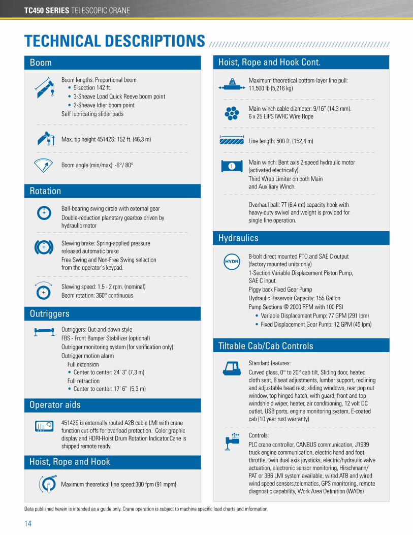
TECHNICAL DESCRIPTIONS / / / / / / / / / / / / / / / / / / / / / / / / / / / / / / / / / / / / / / / / / / / / / / / / / / / / / / / /
Boom lengths: Proportional boom • 5-section 142 ft. • 3-Sheave Load Quick Reeve boom point • 2-Sheave Idler boom pointSelf lubricating slider pads
Max. tip height 45142S: 152 ft. (46,3 m)
Boom angle (min/max): -6°/ 80°
Maximum theoretical line speed:300 fpm (91 mpm)
Maximum theoretical bottom-layer line pull: 11,500 lb (5,216 kg)
Main winch cable diameter: 9/16” (14,3 mm). 6 x 25 EIPS IWRC Wire Rope
Line length: 500 ft. (152,4 m)
Main winch: Bent axis 2-speed hydraulic motor (activated electrically)Third Wrap Limiter on both Main and Auxiliary Winch.
Overhaul ball: 7T (6,4 mt) capacity hook with heavy-duty swivel and weight is provided for single line operation.
Outriggers: Out-and-down styleFBS - Front Bumper Stabilizer (optional)Outrigger monitoring system (for verification only) Outrigger motion alarm Full extension • Center to center: 24' 3" (7,3 m) Full retraction • Center to center: 17' 6" (5,3 m)
Slewing brake: Spring-applied pressure released automatic brakeFree Swing and Non-Free Swing selection from the operator's keypad.
Slewing speed: 1.5 - 2 rpm. (nominal)Boom rotation: 360° continuous
Ball-bearing swing circle with external gearDouble-reduction planetary gearbox driven by hydraulic motor
8-bolt direct mounted PTO and SAE C output (factory mounted units only)1-Section Variable Displacement Piston Pump, SAE C input.Piggy back Fixed Gear PumpHydraulic Reservoir Capacity: 155 GallonPump Sections @ 2000 RPM with 100 PSI • Variable Displacement Pump: 77 GPM (291 lpm) • Fixed Displacement Gear Pump: 12 GPM (45 lpm)
45142S is externally routed A2B cable LMI with crane function cut-offs for overload protection. Color graphic display and HDRI-Hoist Drum Rotation Indicator.Cane is shipped remote ready.
1
Outriggers
Boom
Tiltable Cab/Cab Controls
Controls: PLC crane controller, CANBUS communication, J1939 truck engine communication, electric hand and foot throttle, twin dual axis joysticks, electric/hydraulic valve actuation, electronic sensor monitoring, Hirschmann/PAT or 3B6 LMI system available, wired ATB and wired wind speed sensors,telematics, GPS monitoring, remote diagnostic capability, Work Area Definition (WADs)
Standard features: Curved glass, 0° to 20° cab tilt, Sliding door, heated cloth seat, 8 seat adjustments, lumbar support, reclining and adjustable head rest, sliding windows, rear pop out window, top hinged hatch, with guard, front and top windshield wiper, heater, air conditioning, 12 volt DC outlet, USB ports, engine monitoring system, E-coated cab (10 year rust warranty)
Data published herein is intended as a guide only. Crane operation is subject to machine specific load charts and information.
15
NOTES / / / / / / / / / / / / / / / / / / / / / / / / / / / / / / / / / / / / / / / / / / / / / / / / / / / / / / / / / / / / / / / / / / / / / / / / / / / / / / / / / / / / / / / / / / / / / / / / / /
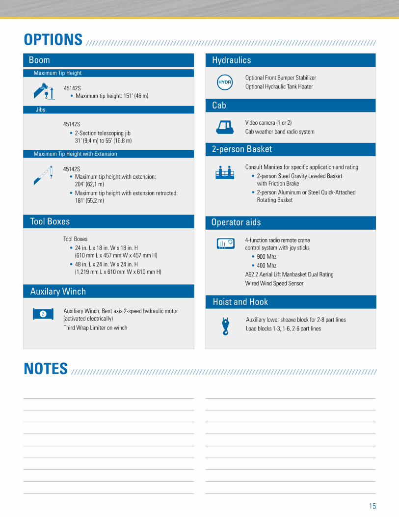
OPTIONS / / / / / / / / / / / / / / / / / / / / / / / / / / / / / / / / / / / / / / / / / / / / / / / / / / / / / / / / / / / / / / / / / / / / / / / / / / / / / / / / / / / / / / / / / / / / /Boom
45142S • Maximum tip height with extension: 204' (62,1 m) • Maximum tip height with extension retracted: 181' (55,2 m)
4-function radio remote crane control system with joy sticks • 900 Mhz • 400 MhzA92.2 Aerial Lift Manbasket Dual RatingWired Wind Speed Sensor
Maximum Tip Height
Maximum Tip Height with Extension
Optional Front Bumper StabilizerOptional Hydraulic Tank Heater
Consult Manitex for specific application and rating • 2-person Steel Gravity Leveled Basket with Friction Brake • 2-person Aluminum or Steel Quick-Attached Rotating Basket
45142S • 2-Section telescoping jib 31' (9,4 m) to 55' (16,8 m)
Jibs
Hydraulics
Cab
2-person Basket
45142S • Maximum tip height: 151' (46 m)
Video camera (1 or 2)Cab weather band radio system
Auxiliary lower sheave block for 2-8 part linesLoad blocks 1-3, 1-6, 2-6 part lines
Hoist and Hook
Operator aids
Tool Boxes • 24 in. L x 18 in. W x 18 in. H (610 mm L x 457 mm W x 457 mm H) • 48 in. L x 24 in. W x 24 in. H (1,219 mm L x 610 mm W x 610 mm H)
Tool Boxes
Auxiliary Winch: Bent axis 2-speed hydraulic motor (activated electrically)
Third Wrap Limiter on winch
Auxilary Winch
2
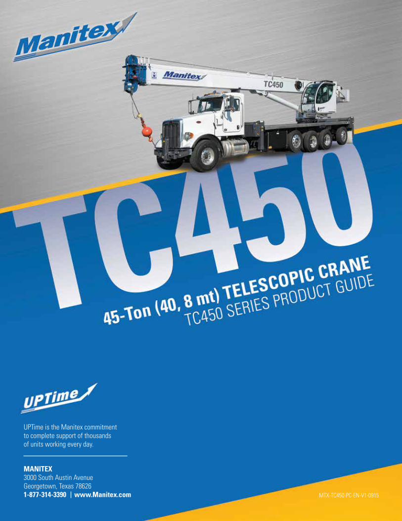
UPTime is the Manitex commitment to complete support of thousands of units working every day.
MANITEX 3000 South Austin Avenue Georgetown, Texas 786261-877-314-3390 www.Manitex.com MTX-TC450-PC-EN-V1-0915


