21
DATA TRANSMISSION &TELEMETRY NITTTR Sec-26 CHANDIGARH
| Date post: | 17-Aug-2015 |
| Category: |
Technology |
| Upload: | chandresh-kumar |
| View: | 16 times |
| Download: | 0 times |
DATA TRANSMISSION &TELEMETRY
NITTTR Sec-26CHANDIGARH
TELEMETRY
Submitted To Submitted By Chandresh KumarMrs. Ritula thakur ME.(E.E.I&C) Roll
No.141503(Modular)
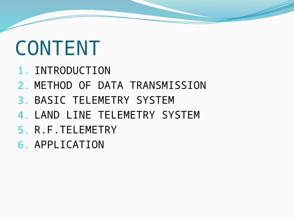
CONTENT1. INTRODUCTION2. METHOD OF DATA TRANSMISSION3. BASIC TELEMETRY SYSTEM4. LAND LINE TELEMETRY SYSTEM5. R.F.TELEMETRY6. APPLICATION

INTRDUCTIONTelemetry is the highly automated
communication process by which measurement are made and other data collected at remote and transmitted to receiving
equipment for monitoring recording and analysis

Method of Data TransmissionThe method employed for data transmission
depend upon the variable& distance over which
data has to be transmitted1. Hydraulic Transmission2. Pneumatic Transmission3. Electrical and electronics Transmission

GENERAL TELEMETRY SYSTEM
Primary Sensing Element
TelemeterTransmitter
TelemeterChannel
TelemeterReceiver
Measurand
End Device
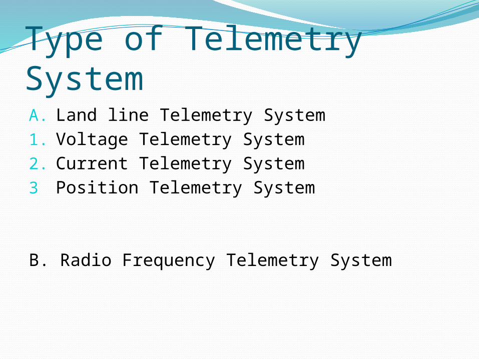
Type of Telemetry SystemA. Land line Telemetry System1. Voltage Telemetry System2. Current Telemetry System3 Position Telemetry System
B. Radio Frequency Telemetry System
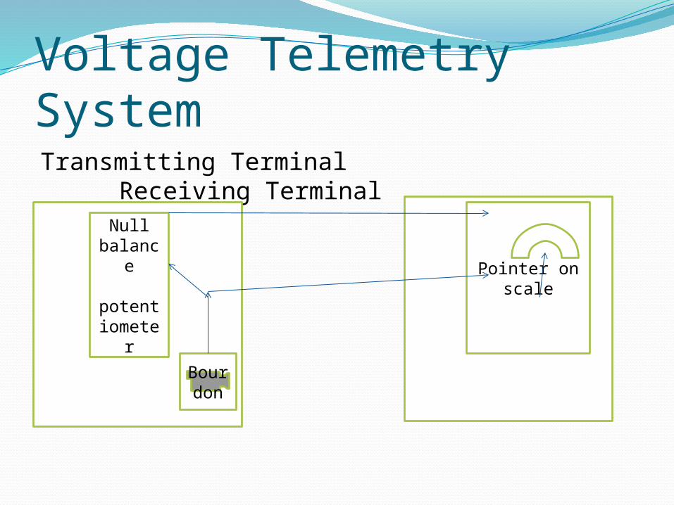
Voltage Telemetry SystemTransmitting Terminal Receiving
Terminal
EEEEEEnb
Pointer on scale
Bourdon
Null balanc
e
potentiometer

R F Telemetry System (a) There is no physical link between Transmitting and
Receiving station (b) The transmitter comprises a RF modulator (AM or FM
type, depending on the performance, bandwidth and cost considerations) and an amplifier.
(c) The receiver comprises an amplifier and a demodulator (AM or FM type as required to match the type of the modulator).
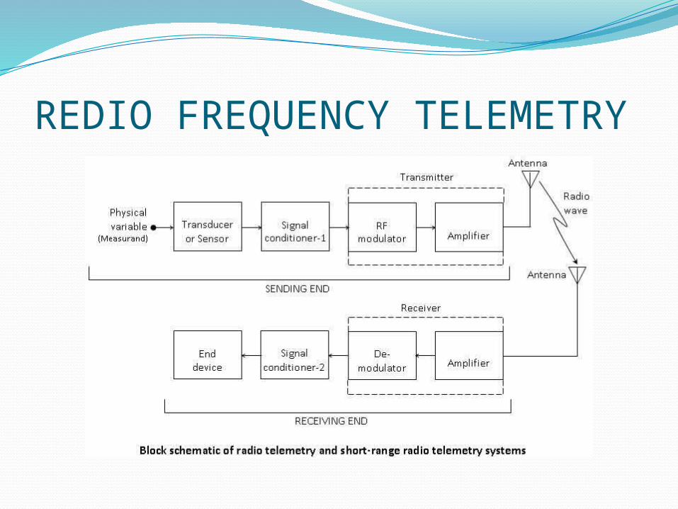
REDIO FREQUENCY TELEMETRY
Telemetry System
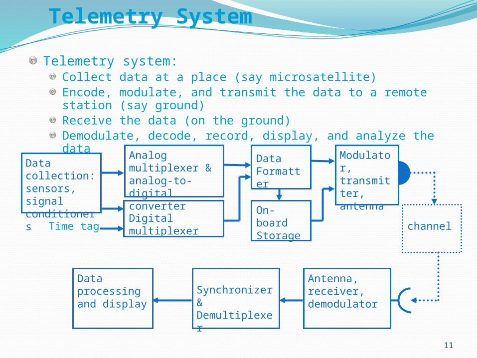
Telemetry system:Collect data at a place (say microsatellite)Encode, modulate, and transmit the data to a remote station (say ground)Receive the data (on the ground)Demodulate, decode, record, display, and analyze the data
11
Data collection: sensors, signal conditioners
Analog multiplexer & analog-to-digital converter
Synchronizer & Demultiplexer
Data processing and display
channel
Modulator, transmitter, antenna
Antenna, receiver, demodulator
Digital multiplexer Time tag
Data Formatter
On-board Storage
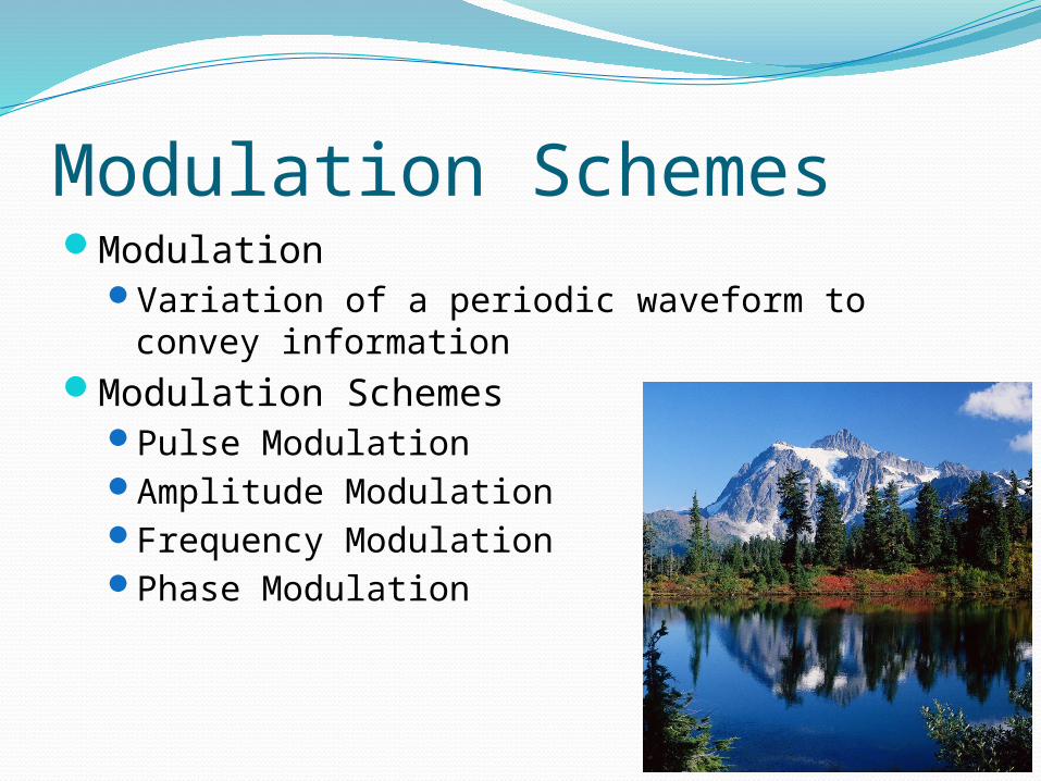
Modulation SchemesModulation
Variation of a periodic waveform to convey information
Modulation SchemesPulse ModulationAmplitude ModulationFrequency ModulationPhase Modulation
13
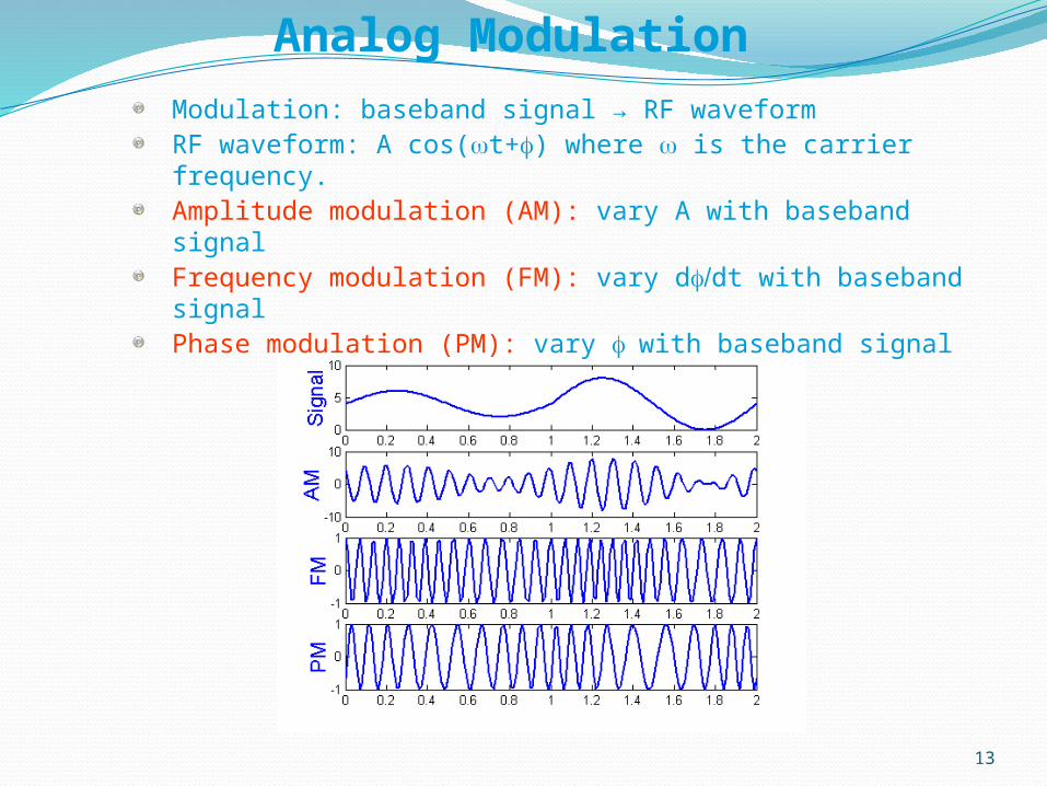
Analog Modulation
Modulation: baseband signal → RF waveformRF waveform: A cos(wt+f) where w is the carrier frequency.Amplitude modulation (AM): vary A with baseband signalFrequency modulation (FM): vary d /f dt with baseband signalPhase modulation (PM): vary f with baseband signal
14
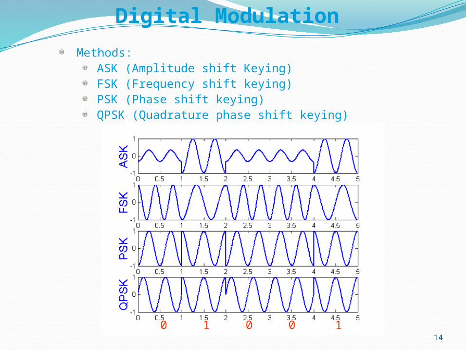
Digital Modulation
Methods:ASK (Amplitude shift Keying)FSK (Frequency shift keying)PSK (Phase shift keying)QPSK (Quadrature phase shift keying)
0 1 100
Multiplexing
When a series of input signals from different sources have to be transmitted along the same physical channel, multiplexing is used to allow several communication signals to be transmitted over a single medium.Frequency division multiplexing (FDM)
FDM places multiple incoming signals on different frequencies. Then are they are all transmitted at the same time The receiving FDM splits the frequencies into multiple signals again
Time division multiplexing (TDM) TDM slices multiple incoming signals into small time intervals Multiple incoming lines are merged into time slices that are transmitted via satellite The receiving TDM splits the time slices back into separate signals
15
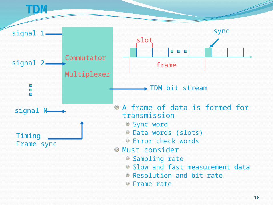
TDM
A frame of data is formed for transmissionSync wordData words (slots)Error check words
Must considerSampling rateSlow and fast measurement dataResolution and bit rateFrame rate
16
signal 1
Commutator
Multiplexer
signal 2
signal N
TDM bit stream
TimingFrame sync
frame
slotsync
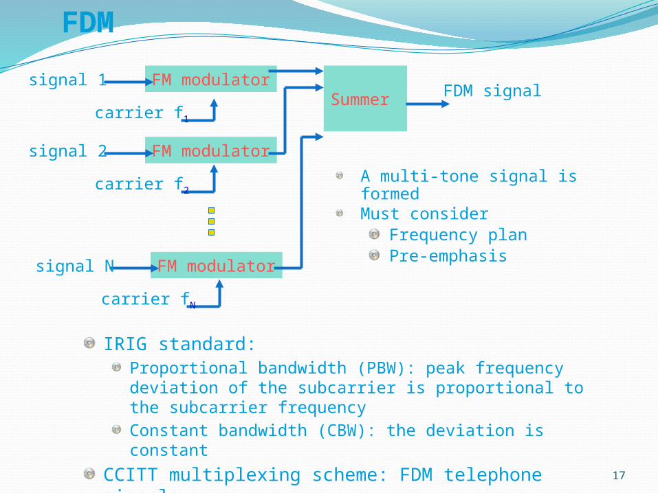
FDM
IRIG standard:Proportional bandwidth (PBW): peak frequency deviation of the subcarrier is proportional to the subcarrier frequency
Constant bandwidth (CBW): the deviation is constant
CCITT multiplexing scheme: FDM telephone signals
17
FM modulatorsignal 1
carrier f1
FM modulatorsignal 2
carrier f2
FM modulatorsignal N
carrier fN
Summer FDM signal
A multi-tone signal is formedMust consider
Frequency planPre-emphasis

Military Communications Architecture

APPLICATION1. Meteorology2. Oil and gas industry3. Space science4. Motor racing5. Agriculture6. Water management7. Swimming Pools8. Defense, space and resource exploration9. Rocketry10. Flight testing
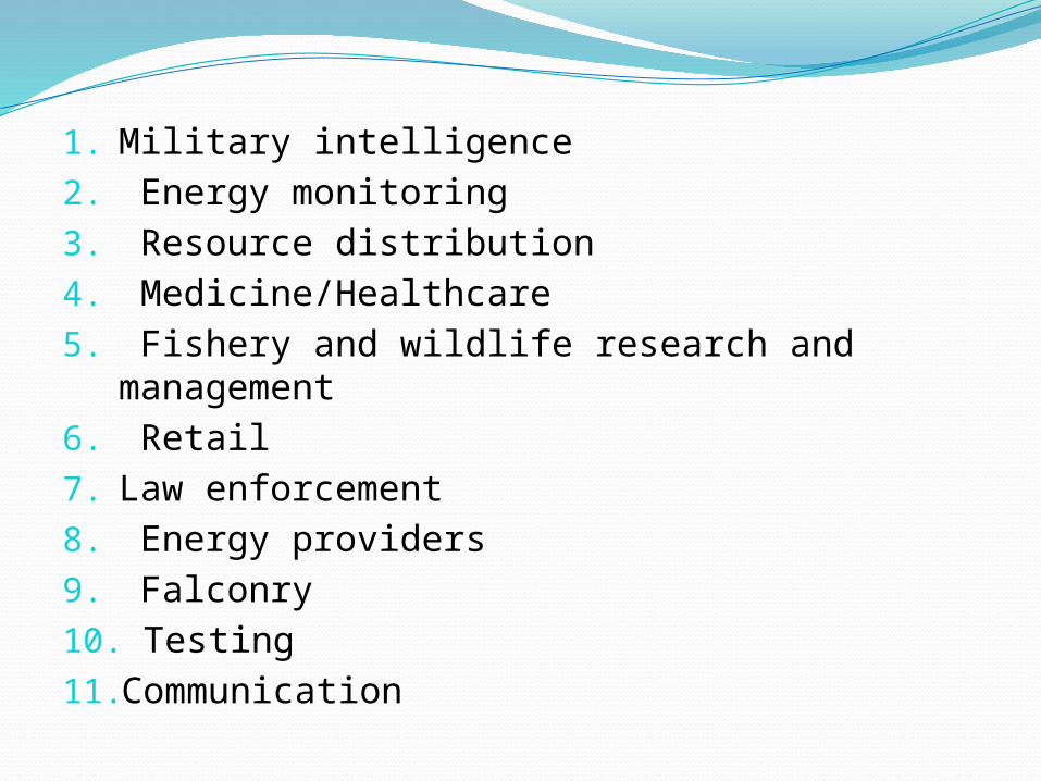
1. Military intelligence2. Energy monitoring3. Resource distribution4. Medicine/Healthcare5. Fishery and wildlife research and
management6. Retail7. Law enforcement8. Energy providers9. Falconry10. Testing11.Communication

THANK YOU