50th International Conference on Environmental Systems ICES-2021-73 12-15 July 2021
Copyright © 2021 Fraunhofer Institute for Laser Technology
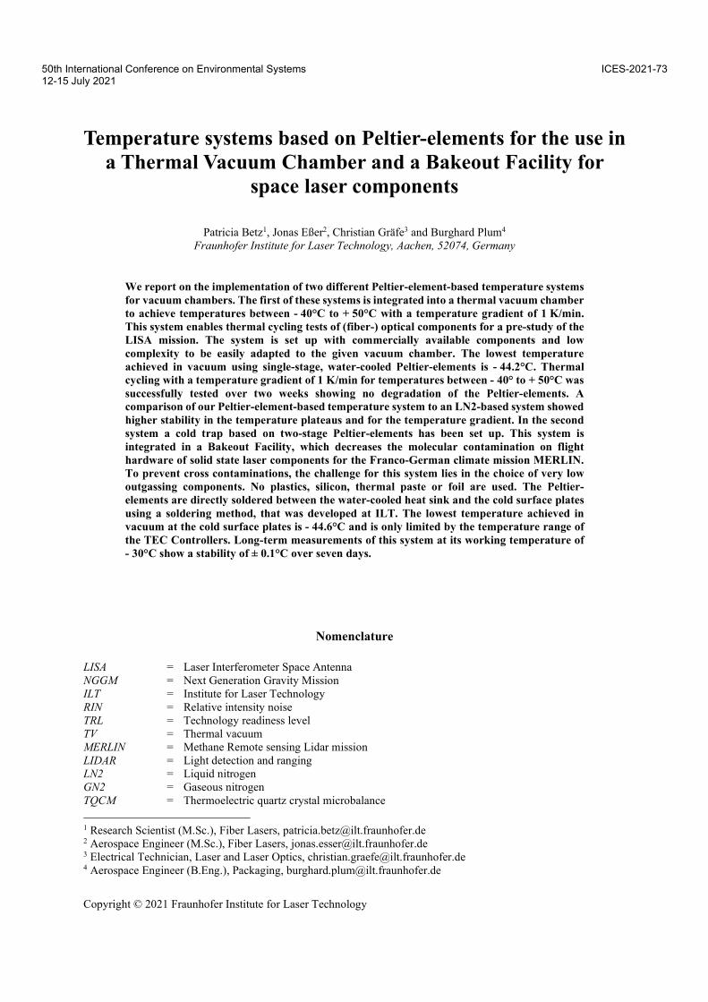
Temperature systems based on Peltier-elements for the use in
a Thermal Vacuum Chamber and a Bakeout Facility for
space laser components
Patricia Betz1, Jonas Eßer2, Christian Gräfe3 and Burghard Plum4
Fraunhofer Institute for Laser Technology, Aachen, 52074, Germany
We report on the implementation of two different Peltier-element-based temperature systems
for vacuum chambers. The first of these systems is integrated into a thermal vacuum chamber
to achieve temperatures between - 40°C to + 50°C with a temperature gradient of 1 K/min.
This system enables thermal cycling tests of (fiber-) optical components for a pre-study of the
LISA mission. The system is set up with commercially available components and low
complexity to be easily adapted to the given vacuum chamber. The lowest temperature
achieved in vacuum using single-stage, water-cooled Peltier-elements is - 44.2°C. Thermal
cycling with a temperature gradient of 1 K/min for temperatures between - 40° to + 50°C was
successfully tested over two weeks showing no degradation of the Peltier-elements. A
comparison of our Peltier-element-based temperature system to an LN2-based system showed
higher stability in the temperature plateaus and for the temperature gradient. In the second
system a cold trap based on two-stage Peltier-elements has been set up. This system is
integrated in a Bakeout Facility, which decreases the molecular contamination on flight
hardware of solid state laser components for the Franco-German climate mission MERLIN.
To prevent cross contaminations, the challenge for this system lies in the choice of very low
outgassing components. No plastics, silicon, thermal paste or foil are used. The Peltier-
elements are directly soldered between the water-cooled heat sink and the cold surface plates
using a soldering method, that was developed at ILT. The lowest temperature achieved in
vacuum at the cold surface plates is - 44.6°C and is only limited by the temperature range of
the TEC Controllers. Long-term measurements of this system at its working temperature of
- 30°C show a stability of ± 0.1°C over seven days.
Nomenclature
LISA = Laser Interferometer Space Antenna
NGGM = Next Generation Gravity Mission
ILT = Institute for Laser Technology
RIN = Relative intensity noise
TRL = Technology readiness level
TV = Thermal vacuum
MERLIN = Methane Remote sensing Lidar mission
LIDAR = Light detection and ranging
LN2 = Liquid nitrogen
GN2 = Gaseous nitrogen
TQCM = Thermoelectric quartz crystal microbalance
1 Research Scientist (M.Sc.), Fiber Lasers, [email protected] 2 Aerospace Engineer (M.Sc.), Fiber Lasers, [email protected] 3 Electrical Technician, Laser and Laser Optics, [email protected] 4 Aerospace Engineer (B.Eng.), Packaging, [email protected]
International Conference on Environmental Systems
2
TEC = Thermoelectric Cooler
NTC = Negative temperature coefficient
CTE = Coefficient of Thermal Expansion
I. Introduction
the Fraunhofer Institute for Laser technology, ILT highly stable fiber amplifiers are developed. Those fiber
amplifiers are developed for space missions, such as the space born gravitational wave observatory LISA and
the next generation gravity mission (NGGM)1. Both fiber amplifiers have met the requirements, regarding power,
polarization, relative intensity noise (RIN) and frequency stability, successfully1,2. By surpassing environmental
testing on component level and on complete system level successfully, the fiber amplifier for NGGM has reached
TRL51. For the fiber amplifier of the LISA laser pre-study environmental testing has not started and is planned in the
current phase of the project. Environmental testing on component level for fiber optical components, such as optical
isolators, pump combiner, tap-coupler, etc. is planned in the first phase of testing. An example for optical fiber
components to be tested is given in Figure 1 a). Especially operational and non-operational cycling in thermal vacuum,
at a pressure of ≤ 10-5 mbar, belong to the test campaign. For the thermal vacuum tests we have set up a thermal
vacuum (TV) chamber with a temperature system based on Peltier-elements.
Figure 1: a) Exemplary fiber optical components, prepared for environmental testing of spaceborn fiber
amplifiers. b) The optical laser bench in the pressurized housing for the MERLIN mission.
In a second implementation, we use Peltier-elements to set up the cold trap for a Bakeout Facility. This Bakeout
Facility is required to reduce the molecular contamination on flight hardware for solid state laser components. These
components belong to the laser optical bench, which will be assembled at ILT, for the Franco-German climate mission
MERLIN. In the MERLIN mission the methane concentration in the earth’s atmosphere will be measured with a light
detection and ranging setup (LIDAR)3,4,5,6. The laser optical bench and its pressurized housing6 are shown in Figure 1
b). During storage, transportation, and the mission itself (duration of minimum three years) the complex laser system
has to withstand environmental loads such as thermal, vibrational and shock loads. In addition, critical requirements
for the laser system are the outgassing rates of the integrated materials and resulting contamination of sensitive laser
optics. One requirement for the laser is to avoid organic components as far as possible, to reduce outgassing to a
minimum and to increase the lifetime of the laser3,4,5,6. To achieve this, a new design with only soldered or screwed
interfaces for the mounting and alignment of the optical components was developed at ILT within the OPTOMECH
projects. Also, the components of the electrical and thermal harnesses are soldered with flux-free solder5. Even though
the utilized components for MERLIN already have a high cleanliness level, the cleanliness requirements of the mission
are stringent. Therefore a cleaning of molecular contamination within a Bakeout Facility before integration of the
components is necessary.
In the next chapters a short introduction on the conventional utilized temperature systems in TV chambers is given
and why Peltier-elements are the best choice for our application. Then the two developed Peltier-element-based
temperature systems for the TV chamber and the Bakeout Facility are explained in detail. The measurement results
for both systems and a short outlook are given. We close this report with a brief summary of the presented work.
At
International Conference on Environmental Systems
3
II. Requirements for temperature systems
In the table below the requirements for both thermal vacuum processes are described. While the bakeout process
requirements are derived from the high cleanliness requirements for the MERLIN mission and to reduce the molecular
contamination to a minimum, The requirements on the TV chamber are derived to fulfill the fiber optical components
testing from LISA laser pre-study.
Table 1: Requirements for thermal testing and bakeout
TV chamber for fiber optical
components testing
Bakeout Facility MERLIN
Pressure ≤ 10-5 mbar ≤ 10-6 mbar
Minimum temperature - 40°C ≤ - 30°C at cold trap
Maximum temperature + 50°C + 45°C for flight hardware
100°C for chamber cleaning
Temperature gradient 1 K/min ≤ 1 K/min
For heating and cold trap
Stability at working temperature ± 5.0°C ± 0.5°C
For heating and cold trap
Operating modes Operational: constant holding of
one temperature
Non-Operational: 48h thermal
cycling with 3h temperature dwell
time
Keeping of a constant temperature
No thermal cycling required
Cleanliness Molecular (MOC) samples:
< 100 ng/cm²
Particle fallout (PFO) samples:
< 50 ppm
(in current phase not applicable)
Molecular (MOC) samples:
< 100 ng/cm²
Particle fallout (PFO) samples:
< 50 ppm
Based on these requirements we studied the state of the art of temperature systems of currently used TV chambers
and Bakeout Facilities. Further we briefly sum up the advantages and disadvantages of these temperature systems and
evaluate the most suited technology for our application in dependence of the given infrastructure.
III. Heating and Cooling in Thermal Vacuum Chambers
Thermal vacuum chambers and space simulation chambers are used by numerous space agencies, research
institutes and in the aerospace industry for spacecraft and flight hardware testing, as well as for qualification purposes.
The state of the art temperature control technologies are so called shrouds, which can be used for cooling and
heating7,8,9,10. A shroud basically consists of a helically bended tubing structure inside a vacuum chamber with a high
emissive and low reflective surface, which is flowed through by a cooling or heating fluid/gas providing the required
temperatures. Shroud systems are indispensable for an adequate simulation of space environment. Some specialized
TV chambers are equipped with additional heat sources in form of xenon or infrared lamps to simulate sunlight
radiation for environmental testing10.
If not a complete homogenous tempered environment for testing is required, less complex temperature stabilized
structures can be utilized. For such applications, plates flowed with the cooling and heating fluid, are a more cost
effective and an easier solution compared to shrouds7,10.
A. Temperature systems
The most common cooling fluids/gases for the described shroud systems are liquid nitrogen (LN2) and gaseous
helium. With LN2 temperatures down to 80 K can be reached and with helium 20 K. There a two major advantages
International Conference on Environmental Systems
4
in using LN2 or helium9,10. First it is a very well known cooling technology in the aerospace research and industry and
therefore well studied. Second, due to the use of gases or liquids with a high purity, a leakage in the shroud system
leads not to a contamination of the chamber or the flighthardware under test. The disadvantages of this cooling
technology are its highly specialized infrastructure with isolated piping systems, special treatment of cryogenic
materials and high initial purchase and running costs. For most small research institutes to build up the infrastructure
required, the costs exceed the budget.
For heating of the shroud systems gaseous nitrogen (GN2) is commonly used. The advantage in using GN2 for
heating is, that in case of a leakage only clean gas enters the chamber and no contamination of the chamber and the
components under test occurs10. As for LN2 and gaseous helium, GN2 has a similar disadvantage in requiring a
correspondingly high amount of gas to sufficiently temper the given shroud system. In addition an infrastructure, to
handle higher volumes of gases, is required.
Due to the required complex infrastructures for LN2, helium and GN2 as cooling and heating technology, these
options are not applicable for our temperature systems.
For some applications, so called liquid chillers are a possible solution for cooling and heating by requiring only
one set up. Within these chillers a liquid is pumped through a heater-chiller, which regulates the temperature of the
liquid, and is pumped further to the required spot. Depending on the chosen fluid, heating and cooling over a certain
range is possible. In case of certain silicone oils the temperature can range from - 70°C to + 100°C10. One disadvantage
of liquid chillers is their high initial purchase and the running costs for specialized fluids. A major disadvantage
regarding cleanliness, is a leakage of silicon oil. This can contaminate the vacuum chamber or even worse the
components for testing. Therefore this option is a high cleanliness risk and not suited for both of our applications.
As a heating source for TV chambers without a shroud or as additional source, electrical heaters or infrared lamps
are possible sources7,8,9,10. The advantage of these heat sources is their modular adjustment to any given TV chamber
architecture due to their varying geometries and powers. A disadvantage is the need of a separate control unit, resulting
in a higher cost and another control interface. Due to its only capability to heat, electrical heaters and infrared lamps
are not suited for our applications.
An unconventional temperature stabilization in TV chambers is the utilization of Peltier-elements. Peltier-elements
are semiconductor-based temperature converters. According to the Peltier effect by applying a current a temperature
difference is created and vice versa11. Therefore cooling and heating in one device with only one control unit is
possible. In general the geometry of Peltier-elements can range from few mm² to several tens mm² and can even be of
rectangular or customized shapes. With these small geometries, the usage of Peltier-elements is not optimally suited
to be operated in large space simulators of several meters in diameter. In addition the thermal load is not a negligible
driver on the required amount of Peltier-elements. Depending on the test component and its thermal load, too many
of them would be required and the amount of control units scales with the amount of required Peltier-elements. But
for small TV chambers (< 1 m) they are a reasonable possibility. Another disadvantage in using Peltier-elements in
TV chamber applications is the lack of knowledge on the long-term behavior, such as degradation, and maintenance
on such systems. The advantages of Peltier-elements are that no specialized infrastructure as for LN2 is required and
the possibility to manufacture them free of organic materials.
Due to the small geometries of our applications (< 1 m), the small optic components under test with a low thermal
load, less required infrastructure, the cost effective initial purchase and running cost, as well as a high cleanliness level
of the used materials, we decide to set up our temperature systems with Peltier-elements.
B. Conception of Peltier-element-based temperature system for fiber optical component testing
Therefore, we attempt to convert a cylindrical vacuum chamber with a diameter of 520 mm with a temperature-
controlled plate based on Peltier-elements into a thermal vacuum chamber. We choose to use a temperature stabilized
plate concept, due to the small geometries of the fiber optical components. The fiber optical components have a
maximum sizing of 70 mm x 12 mm x 7 mm or even smaller. For the Peltier-elements we choose 40 mm x 40 mm
one stage Peltier-elements with a maximum current of 6 A. One stage Peltier-elements have in comparison to the
cascaded ones larger geometries and a lower maximum temperature difference between cold and hot side, around
80 K. For this application a max. temperature difference of 80 K is sufficient. With a TEC Source supplying 30 A and
28 V to the Peltier-elements, six of these Peltier-elements can be connected in parallel. To supply a sufficient heat
International Conference on Environmental Systems
5
dissipation underneath the Peltier-elements a water-cooled heat sink is implemented. On top of the Peltier-elements is
positioned the thermal active plate , where the required temperature is regulated and the fiber optical components are
mounted. Due to lower cleanliness requirements in this case, heat connection between the Peltier-elements and the
mechanic is realized by thermal paste. The complete temperature system is screwed to ensure easy maintenance in
case of degradation. Due to the high load alternations brought onto the Peltier-elements during the cycling, the
possibility exists that degradation, observable at the current, could arise within several days or weeks.
C. Conception of Peltier-element-based cold trap
In a Bakeout Facility molecular contaminations are removed from components by a controlled heat up of these.
To measure the outgassing rate of this contaminations a thermoelectric quartz crystal microbalance (TQCM) sensor
can be utilized. This sensor is cooled down to low temperatures, e.g. - 20°C, so that the contamination can crystalize
on the outer cooled measurement crystal. The frequency difference between the cold measurement crystal and an
internal reference crystal increases with contaminations settling onto the cold surface12. To prevent the TQCM sensor
to run in saturation, cold traps are required to drag parts of the contamination. In general cold traps are several degrees
colder than the TQCM. For the bakeout processes for the MERLIN mission the TQCM has an operating temperature
at - 20°C resulting in a minimum temperature of -30°C for the cold trap. For such a temperature range, Peltier-elements
are a promising candidate. Since cleanliness is a very important requirement for the components of the MERLIN
mission, we decide to go for a scalable cold trap based on Peltier-elements. Therefore a sufficient water-cooled heat
sink is required and plates, which are cooled by the Peltier-elements towards the required - 30°C. We choose for this
application two-stage Peltier-elements due to higher temperature differences occurring in the Bakeout Facility from
- 30°C up to > 100°C in case of vacuum chamber cleaning. Due to the high cleanliness requirements of the MERLIN
mission the Peltier-elements contain no organic materials. In addition we decided to solder the Peltier-elements to the
mechanics, because thermal foil and paste are prohibited. Because of the presumed more rigid soldering connection
of the Peltier-elements, compared to thermal paste or foil, the possibility of degradation can occur. The degradation
could arise after several days or weeks.
IV. Peltier-element-based temperature system for fiber optical component testing
In this part the Peltier-element-based temperature system of the TV chamber for fiber optical components testing
and the measurement results until now are described. As shown in Table 1, important parameters for the temperature
system are e.g. the thermal cycling from - 40°C to + 50°C with a temperature gradient of 1 K/min. To fulfill these
requirements a cylindrical vacuum chamber (Figure 2 a)) is equipped with the Peltier-element-based temperature
system.
Figure 2: a) Cylindrical vacuum chamber (Diameter: 520 mm; Height: 600 mm). b) Conceptual design of
Peltier-element-based temperature system.
A. Set up of temperature system
To fit the system in the vacuum chamber and to have sufficient space for fiber optical components, the mechanical
parts, such as heat sink and thermal active plate are adapted. The sizes of the mechanical parts are depicted in a
conceptual design in Figure 2 b).
International Conference on Environmental Systems
6
The thermal active plate is very thin to reduce heat capacity, but still having enough stability to prevent the plate
from bending due to clamping by screw connection. Both plates are manufactured out of AlMg4,5Mn.
To determine an optimized cooling structure for the Peltier-elements and to reach - 40°C, simulations are
performed. As total heat dissipation we assume 600 W with a water flow of 400 l/hour at a water temperature between
16°C and 20°C. According to the simulation results, the cooling structures are manufactured with a diameter of 8 mm.
The water temperature for the cooling is set to 16°C and the water flow rate can be set to a maximum of 800 l/hour.
The completed setup of the temperature system is shown in Figure 3.
Figure 3: a) Rendering of the temperature system in a CAD-model with transparent thermal active plate. b)
The realized temperature system set up in the vacuum chamber.
B. Experimental results
In the first tests the lowest achievable temperature at the active thermal plate is evaluated in dependence of the
water flow. The water cooling temperature was set to 16°C with a water flow through the heat sink starting at
200 l/hour up to 800 l/hour. No thermal load in form of components or comparable, is brought onto the system. At
- 38°C with a water flow of 200 l/hour, the TEC Controller reaches its current limit at 30 A and therefore can not drive
the system towards lower temperatures. By increasing the water flow the heat dissipation from the Peltier-elements
increases and lower temperatures are possible. At a water flow of 300 l/hour - 40.6°C are measured. With a maximum
water flow of 800 l/hour we achieved - 44.2°C at the thermal active plate. With - 44.2°C the temperature system
successfully met the requirement of - 40°C. By exchanging the TEC Controller even lower temperatures can be
reached.
In the next step we test the cycle capability from - 40°C to + 50°C with a temperature gradient of 1 K/min and
dwell time of three hours. The water cooling stayed at 16°C at a water flow of 800 l/hour. For the first testing only
one cycle was recorded. The results are shown in Figure 4.
Figure 4: Temperature and power consumption of the Peltier-element-based temperature system for thermal
cycling.
International Conference on Environmental Systems
7
The required temperatures, gradient and dwell times are successfully reached. We observed no TEC controller
(e.g. current) driven limitations in the temperature gradients. The Peltier-element-based temperature system is well
suited for our application in the given requirements.
The cycle capability has to be further tested for the later designated environmental tests of the fiber optical
components. Therefore four of the fiber optical components with a high thermal influence are chosen and screwed to
the thermal active plate. The components consist of aluminum, optical fibers and UV glue resulting in a total mass of
17.1 g per component. In addition to the NTCs utilized for regulation and measuring, mounted on the thermal active
plate (sensors T1-T2), the NTCs T3 and T4 are positioned on the components. The temperature with the load of the
fiber optical components in principal is achieved with the temperature system. Only the - 40°C are not exactly reached
at the top of the components, as is shown in Figure 5.
Figure 5: Temperature and power consumption of the Peltier-element-based temperature system with four
fiber optical components for exemplary cycling.
The minimum achieved temperature on the components is - 39.6°C at 3.75 hours while the plate temperature is
under - 40°C.
Further on long-term testing to evaluate degradation of the Peltier-elements during cycling has been performed.
Before the test for all six Peltier-elements starts, their resistance was measured to be able to compare it after the test.
The long-term test was done over 12 days. The water cooling temperature was set to 16°C and the flow rate was
800 l/hour. This test was done without fiber optical components and therefore the temperature sensors were reduced.
In Figure 6 a) five cycles of the long-term test are depicted. The temperature sensors T1 to T3 were positioned on the
thermal active plate.
Figure 6: a) Detailed view on temperature and electrical power of five cycles during the long-term test. b)
Relative deviation of the electrical power over the 55 cycles of long-term testing.
International Conference on Environmental Systems
8
We observed that the cycling stayed stable over the duration of the test and showed no fluctuations in the
temperature. In Figure 6 b) the relative deviation of the electrical power at the critical temperature of - 40°C is plotted
over the 55 cycles. Slight variations in the region of 0.5% are observed, especially at the beginning of the tests. We
trace these fluctuations down to the infrastructural water temperature, which randomly fluctuates around ± 1°C. The
resistance measurement of the Peltier-elements showed no deviation from the values two weeks before. Resulting
from these observations we assume that no evident degradation of the Peltier-elements in the build up temperature
system has occurred. Regarding to this, the temperature system is capable to run for tests over several weeks without
a fast degradation.
To evaluate our temperature system to the conventional and more common LN2-based systems, a cycling sequence
of the long-term test is compared to a cycling sequence of an LN2-based system. This data is taken from previous
fiber optical components testing for the same requirements as stated in Table 1 left column. The referenced LN2-based
system can operate over a wider temperature range than required and therefore is not as specifically optimized towards
the given requirements as our Peltier-element-based system. Thermal testing was conducted with an LN2-based
system at SpaceTech (STI). The compared results are depicted in Figure 7.
Figure 7: Temperature of the Peltier-element-based temperature system compared with an LN2-based system.
The temperature gradient of the here mentioned LN2-based system is steeper than the gradient of the Peltier-
element temperature system and therefore is faster than 1 K/min. Another peculiarity is observed during the dwell
times. While the temperature in the plateaus for the Peltier-element system fluctuates around ± 0.3°C the fluctuations
for the LN2-based system are with up to ± 5°C significantly higher. Resulting from this comparison the Peltier-
element-based temperature system is significantly more stable in the temperature as well for the temperature gradient.
During the described experiments we were able to show that a Peltier-element based system is capable to meet the
cycling requirements given for the fiber optical components testing of the LISA laser pre-study. In addition this system
is easier to setup, to handle and to control as compared to the here described LN2-based system, which on the other
hand has the advantage of a wider temperature range.
C. Outlook
We showed with the described Peltier-element-based system that the requirements for the fiber optical components
testing of the LISA laser pre-study are successfully achieved. A possible next point are long-term tests with durations
longer than two weeks to test the degradation of the Peltier-elements in the time span of months and to verify when
an exchange of the Peltier-elements is necessary. Independent of these long-term tests, the Peltier-element-based
temperature system is ready for the environmental test campaign.
International Conference on Environmental Systems
9
V. Peltier-element-based Cold Trap of Bakeout Facility
In this part the Peltier-element-based cold trap for the Bakeout Facility and its measurement results until now
are described. According to Table 1 the minimum temperature of the cold trap has to be - 30°C ± 0.5°C and high
cleanliness requirements are demanded.
To prevent the TQCM sensor to run in its saturation point during a bakeout process the cold trap should be in close
vicinity to the sensor. Based on the positions for pumps, electric, etc. in the vacuum chamber and gravitational forces
working on the cold trap, the most suited place for the cold trap is at the ceiling of the vacuum chamber (Figure 8).
Figure 8: Position of Peltier-element-based cold trap at the ceiling of the Bakeout Facility.
Depending on this position and the utilized Peltier-elements, the heat sink and cold surface plates have the
dimensions as shown in Figure 9 a).
Figure 9: a) Top view on to the conceptual design of the cold trap. b) Fully functional set up of the cold trap
inside the Bakeout Facility.
There are three cold surface plates in total. In the heat sink water cooling structures are integrated with a diameter of
8.8 mm running directly underneath the Peltier-elements. The thickness of the cold surface plates is with 1 mm as thin
as possible to reduce the thermal capacity to a minimum. As these plates have not to withstand forces by mounting
components in contrast to the plate from the TV chamber, bending of the plates is not an issue. The cold trap mechanic
is manufactured out of Molybdenum-Copper (MoCu). This material was chosen due to its very close CTE to the
Peltier-element ceramics. When Peltier-elements are soldered to mechanics it is very important to keep the CTE
mismatch of the Peltier-elements and the mechanics to a minimum to prevent the Peltier-elements to be torn apart by
the different thermal expansions.
International Conference on Environmental Systems
10
The Peltier-elements are not sealed, to avoid organic material, such as silicone, in the sealing. In addition the
internal solder of the Peltier-elements is able to withstand higher temperatures up, to 238°C, than the solder of other
Peltier-elements. This is important at high temperatures for soldering and bakeout processes. The Peltier-elements are
free of organic material and therefore are within the cleanliness requirements. The Peltier-elements and the cold trap
mechanic are soldered with an Indium solder by a technique developed at ILT. Underneath each cold surface plate
two Peltier-elements are soldered and connected in series. On top of each cold surface plate a PT100 is screwed to
measure the temperature at the Peltier-element pair. All cable isolations belonging to the cold trap are out of Teflon
or Captone. The complete cold trap setup inside the vacuum chamber is depicted in Figure 9 b).
A. Experimental Results
In the first test the lowest achievable temperature at the cold surface plates was evaluated. The vacuum chamber
was evacuated to a pressure of 10-6 mbar. The water cooling temperature and flow was not modified during all tests
and has a value of 17°C at a flow of 120 l/hour. The lowest measurable temperature at the cold surface plates is
- 44.6°C. Only one of the three Peltier-element pairs was used in this test to reduce the risk of damage to the Peltier-
elements possibly occurring at temperatures < - 30°C. With a minimum temperature of - 44.6°C, the result surpasses
the requirement of - 30°C.
At - 44.6°C the TEC controller reaches its temperature limit, so with other TEC controller electronics even lower
temperatures can be achieved as there is still margin in the current of the Peltier-elements of > 30%.
For the next tests the long-term stability at the working point of - 30°C was evaluated and wether a degradation of
the Peltier-elements can be observed. This test was run over a week and all six Peltier-elements were in operation.
The complete measurement is shown in Figure 10.
Figure 10: Detailed view on the temperature stability at - 30°C over one week.
During the seven days the temperature was stabilized to - 30°C with a fluctuation of ± 0.1°C in total (Figure 10).
The current at all three Peltier-element pairs stayed constant over the week showing no degradation. The long-term
stability for the possible duration of a bakeout process is successfully passed by the temperature system. Regarding to
this result and the successfully achieved temperature requirements the cold trap is fully functional for bakeout
processes.
Due to the critical cleanliness requirements of the MERLIN mission and to verify the complete Bakeout Facility
and their functionality, two molecular (MOC) and two particle fallout (PFO) samples were set up in the Bakeout
Facility. With these samples a complete bakeout process, like the MERLIN flight hardware will see it, is performed.
The sample analysis is done by Airbus Defence and Space GmbH. For the bakeout process, the breadboard where
MOC and PFO samples are positioned is heated up to + 45°C, while the TQCM sensor is cooled to - 20°C and the
International Conference on Environmental Systems
11
cold trap to - 30°C. The vacuum chamber is evacuated to a pressure ≤ 10-6 mbar. The bakeout process is finished when
the deviation of the frequency of the TQCM sensor converges towards < 1%. After 104.5 hours this stop criteria was
reached.
The analysis of the samples showed for both MOC samples results of 30.5 ng/cm² and 40.6 ng/cm². No evidence
for silicone could be detected. For the two PFO samples the measured contamination is 6 ppm. Regarding to the
requirements of < 100 ng/cm² (MOC) and < 50 ppm (PFO) the cleanliness of the Bakeout Facility lies well within the
requirements. Therefore the complete Bakeout Facility successfully meets the cleanliness requirement.
B. Outlook
We showed that the Peltier-element-based cold trap is fully functional by meeting the demanding cleanliness
requirements and is now ready to operate in bakeout processes for the MERLIN flight hardware and further following
missions.
VI. Conclusion
In this paper we presented the build up of Peltier-element-based temperature systems, one for thermal cycling and
one as a cold trap for a Bakeout Facility. We showed that temperature systems based on Peltier-elements, in a certain
temperature range, work at least as good as their more common used methods, such as LN2. We even observed more
precision in the temperature stability by an easier operation.
Due to our given infrastructure, Peltier-elements are the best choice because they do not require a specialized
infrastructure. In addition their current costs are less pricy than these of LN2 or liquid chillers. Also the here mentioned
systems can be scaled to higher sizes. Nevertheless they do have a sizing limit compared to the other temperature
systems. For the optical components, which should be tested here, the Peltier-element-based temperature systems are
well suited. We can propose that the approach by setting up Peltier-element-based temperature systems is suited for
all institutes or small companies which do not have an initial infrastructure for thermal testing.
The temperature system for the thermal cycling tests of fiber optical components has been built up with six
commercially available water-cooled one-stage Peltier-elements. The system reached the required temperature of
- 40°C and showed a reliable thermal cycling close to two weeks without degradation of the TECs. Compared with an
LN2-based system the stability during the dwell times has a higher stability ranging at ± 0.1°C and shows a smoother
temperature gradient. The minimum temperature of the system was mainly limited by the utilized power supply. By
utilizing a more powerful power supply lower temperatures can be reached. All temperature requirements for the
thermal testing of the fiber optical components were successfully achieved.
For the next step we plan on studying the long-term stability and degradation of the Peltier-elements in this
temperature system. The TV chamber is in the final preparation for the fiber optical components testing for the LISA
laser pre-study.
For the Bakeout Facility a temperature system as cold trap was built up with only low outgassing components, e.g.
no plastics, silicon and thermal foil or paste. We approached this difficulty by soldering the Peltier-elements to the
dedicated mechanics and using nonorganic materials. Special care was taken in choosing the material MoCu to reduce
the CTE mismatch between Peltier-elements and the mechanics to prolong the lifetime of the Peltier-elements and
their reliability. The water-cooled two-stage Peltier-elements reached in the setup a minimum temperature of - 44.6°C
at the cold surface plates. By extending the temperature range of the TEC controllers, even lower temperatures can be
reached. At the working temperature of - 30°C long-term testing over one week was done. The temperature stability
lies in the range of ± 0.1°C over all until now run tests. No degradation of the Peltier-elements could be observed.
A cleanliness validation with MOC and PFO samples was done to approve the Bakeout Facility for the bakeout
processes of the MERLIN optical and mechanical flight hardware. The validation was completely successful, showing
that for the here described application with the given components the Peltier-element-based cold trap is efficiently
working.
At the beginning of 2021, the bakeout processes for the MERLIN flight hardware are going to start. For this, the
cold trap and the Bakeout Facility are fully functional and ready for the processes.
International Conference on Environmental Systems
12
Acknowledgments
We would like to thank the colleagues from Airbus Defence and Space GmbH for their support during the setup
of the Bakeout Facility and sample analysis. Further we would like to thank SpaceTech (STI) for providing the test
data from previous fiber optical components testing.
References
1Fitzau O., Betz P., Cebeci P., Giesberts M., Hoffmann H-D., et al., “Highly stable fiber lasers for satellite-based gravitational
measurements” Photonics West LASE – SPIE LASE 2017, Proc. of SPIE Vol. 10897, Fiber Lasers XVI: Technology and Systems,
Aachen, 2017, pp. 108972H-1 – 108972H-11
2Dahl K., Cebeci P., Fitzau O., Giesberts M., et al.,“A new laser technology for LISA” International Conference on Space
Optics – ICSO 2018, Proc. of SPIE Vol. 11180, Immenstaad, 2018, pp. 111800C-1 – 111800C-7
3Wührer C., Kühl C., Lucarelli S., Bode M., “MERLIN: Overview of the design status of the Lidar Instrument” International
Conference on Space Optics – ICSO 2018, Proc. of SPIE Vol. 11180, Munich, 2018, pp. 1118028-1 – 1118028-13
4Livrozet M. J., “Design und Charakteristik eines satellitentauglichen optisch-parametrischen Oszillators im nahen Infrarot,”
Ph.D. Dissertation, Rheinisch-Westfälische Technische Hochschule, North-Rhine Westphalia, Aachen, 2018.
5Löhring J., Winzen M., Faidel H., Miesner J., Plum D., et al., “Key optical components for spaceborne lasers” Photonics West
LASE – SPIE LASE 2016, Proc. of SPIE Vol. 9730, Components and Packaging for Laser Systems II, Aachen, 2016, pp. 97300O-
1 – 97300O-11
6Hahn S., Bode M., Luttmann J., Hoffmann H.-D., “FULAS: high energy laser source for future lidar applications” International
Conference on Space Optics – ICSO 2016, Proc. of SPIE Vol. 10562, Munich, 2016, pp. 105620P-1 – 105620-9
7R. S. S. Chisabas, G. Loureiro and C. de Oliveira Lino, Space Thermal and Vacuum Environment Simulation, [online book],
Chapter 2, page 11-28 URL: https://www.semanticscholar.org/paper/Space-Thermal-and-Vacuum-Environment-Simulation-
Chisabas-Loureiro/2539649202fcd61c3b6cbd81c0f8a53db2a446da [cited 08 February 2021].
8S. Jayaram and E. Gonzalez, “Design and construction of a low-cost economical thermal vacuum chamber for spacecraft
environmental testing,” Journal of Engineering, Design and Technology, Vol. 9, No. 1,2011, pp. 47-62.
9J. K. J. Kousal, T. Censký and O. Pladjdicka, “Design and operation of simple thermal vacuum chamber for testing of small
spacecraft components,”International Scientific Conference – New trends in Aviation Development NTAD, IEEE, Prague, 2019,
pp. 102-105
10Ash G. S., “Manufacturing of Cryoshroud Surfaces for Space Simulation Chambers,” White Paper [online], DynaVac,
Hingham, URL: https://dynavac.com/systems/thermal-vacuum/thermal-control/ [cited 08 February 2021].
11Goldsmid J. H., The Physics of Thermoelectric Energy Conversion, [online book], Morgan and Claypool Publishers, 2017,
Chapter 1, URL: https://iopscience.iop.org/book/978-1-6817-4641-8 [cited 07 March 2021]
12Tsuchiya Y., Kukita H., Shiobara T., Yukumatsu K, Miyazaki E., “Twin-CQCM and Twin-TQCM Sensors with Wide
Operating Temperature Range for Outgassing and Atomic Oxygen Measurement”, IEEE Sensors Journal, 10 February 2021 (to be
published)