Recommendation ITU-R BT.2100-0 (07/2016) Image parameter values for high dynamic range television for use in production and international programme exchange BT Series Broadcasting service (television)
Transcript
Recommendation ITU-R BT.2100-0(07/2016)
Image parameter values for high dynamic range television for use in
production and international programme exchange
BT SeriesBroadcasting service
(television)
ii Rec. ITU-R BT.2100-0
Foreword
The role of the Radiocommunication Sector is to ensure the rational, equitable, efficient and economical use of the radio-frequency spectrum by all radiocommunication services, including satellite services, and carry out studies without limit of frequency range on the basis of which Recommendations are adopted.
The regulatory and policy functions of the Radiocommunication Sector are performed by World and Regional Radiocommunication Conferences and Radiocommunication Assemblies supported by Study Groups.
Policy on Intellectual Property Right (IPR)
ITU-R policy on IPR is described in the Common Patent Policy for ITU-T/ITU-R/ISO/IEC referenced in Annex 1 of Resolution ITU-R 1. Forms to be used for the submission of patent statements and licensing declarations by patent holders are available from http://www.itu.int/ITU-R/go/patents/en where the Guidelines for Implementation of the Common Patent Policy for ITU-T/ITU-R/ISO/IEC and the ITU-R patent information database can also be found.
Series of ITU-R Recommendations (Also available online at http://www.itu.int/publ/R-REC/en)
Series Title
BO Satellite deliveryBR Recording for production, archival and play-out; film for televisionBS Broadcasting service (sound)BT Broadcasting service (television)F Fixed serviceM Mobile, radiodetermination, amateur and related satellite servicesP Radiowave propagationRA Radio astronomyRS Remote sensing systemsS Fixed-satellite serviceSA Space applications and meteorologySF Frequency sharing and coordination between fixed-satellite and fixed service systemsSM Spectrum managementSNG Satellite news gatheringTF Time signals and frequency standards emissionsV Vocabulary and related subjects
Note: This ITU-R Recommendation was approved in English under the procedure detailed in Resolution ITU-R 1.
Electronic PublicationGeneva, 2016
ITU 2016
All rights reserved. No part of this publication may be reproduced, by any means whatsoever, without written permission of ITU.
Image parameter values for high dynamic range television for use in production and international programme exchange
(2016)
Scope
High Dynamic Range Television (HDR-TV) provides viewers with an enhanced visual experience by providing images that have been produced to look correct on brighter displays, that provide much brighter highlights, and that provide improved detail in dark areas. This Recommendation specifies HDR-TV image parameters for use in production and international programme exchange using the Perceptual Quantization (PQ) and Hybrid Log-Gamma (HLG) methods.
Keywords
High dynamic range, HDR, television, HDR-TV, image system parameters, television production, international programme exchange, wide colour gamut, perceptual quantization, PQ, hybrid log-gamma, HLG
The ITU Radiocommunication Assembly,
considering
a) that digital television image formats for HDTV and UHDTV have been specified by the ITU-R in Recommendations ITU-R BT.709 and ITU-R BT.2020;
b) that these television image formats have been limited in the image dynamic range they can provide due to their reliance on legacy cathode ray tube (CRT) characteristics that limit image brightness and detail in dark areas;
c) that modern displays are capable of reproducing images at a higher luminance, greater contrast ratio and wider colour gamut than is conventionally employed in programme production;
d) that viewers expect future television viewing to provide improved characteristics compared with the current HDTV and UHDTV in terms of a more realistic sensation, greater transparency to the real world and more accurate visual information;
e) that high dynamic range television (HDR-TV) has been shown to increase viewer enjoyment of television pictures;
f) that HDR-TV provides a “step-change” improvement in viewer experience by means of substantially increased brightness and detail in highlights and diffuse reflecting objects, while providing greater detail in dark areas;
g) that the combination of extended dynamic range and extended colour gamut give HDR-TV a substantially larger colour volume;
h) that the HDR-TV image formats should have, where appropriate, a degree of compatibility with existing workflows and infrastructure;
i) that a reference viewing environment including display parameters should be defined for HDR-TV image formats,
1 The Administrations of France and the Netherlands have expressed concerns regarding the characteristics and performance of HDR-TV. Further studies are needed and may lead to a revision of this Recommendation, as appropriate, under the terms of Resolution ITU-R 1-7.
2 Rec. ITU-R BT.2100-0
further considering
that due to rapid developments in HDR technology the ITU may wish to consider early updates and improvements to this Recommendation,
recognizing
that Report ITU-R BT.2390 contains much information on two methods to achieve HDR-TV,
recommends
that for programme production and international exchange of HDR-TV, the perceptual quantization (PQ) or Hybrid Log-Gamma (HLG) specifications described in this Recommendation should be used.
NOTE – The PQ specification achieves a very wide range of brightness levels for a given bit depth using a non-linear transfer function that is finely tuned to match the human visual system. The HLG specification offers a degree of compatibility with legacy displays by more closely matching the previously established television transfer curves. Conversion between these formats may be accomplished using the approach illustrated in informative Annex 2.
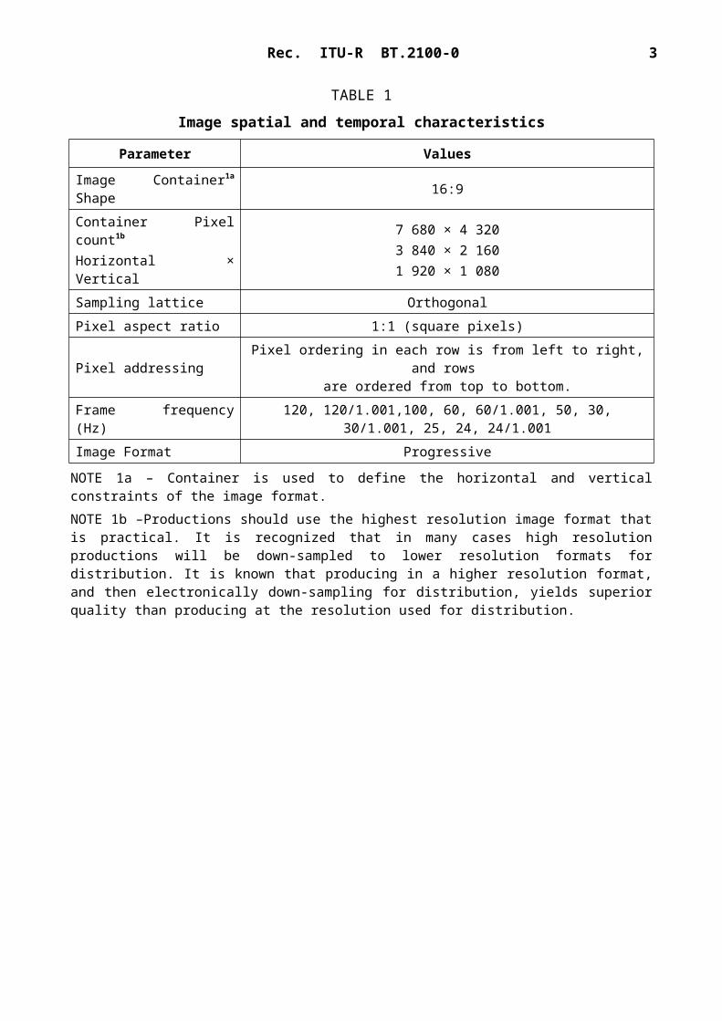
TABLE 1
Image spatial and temporal characteristics
Parameter Values
Image Container1a Shape 16:9
Container Pixel count1b Horizontal × Vertical
7 680 × 4 3203 840 × 2 1601 920 × 1 080
Sampling lattice OrthogonalPixel aspect ratio 1:1 (square pixels)
Pixel addressing Pixel ordering in each row is from left to right, and rows are ordered from top to bottom.
Frame frequency (Hz) 120, 120/1.001,100, 60, 60/1.001, 50, 30, 30/1.001, 25, 24, 24/1.001Image Format Progressive
NOTE 1a – Container is used to define the horizontal and vertical constraints of the image format.NOTE 1b –Productions should use the highest resolution image format that is practical. It is recognized that in many cases high resolution productions will be down-sampled to lower resolution formats for distribution. It is known that producing in a higher resolution format, and then electronically down-sampling for distribution, yields superior quality than producing at the resolution used for distribution.
Rec. ITU-R BT.2100-0 3
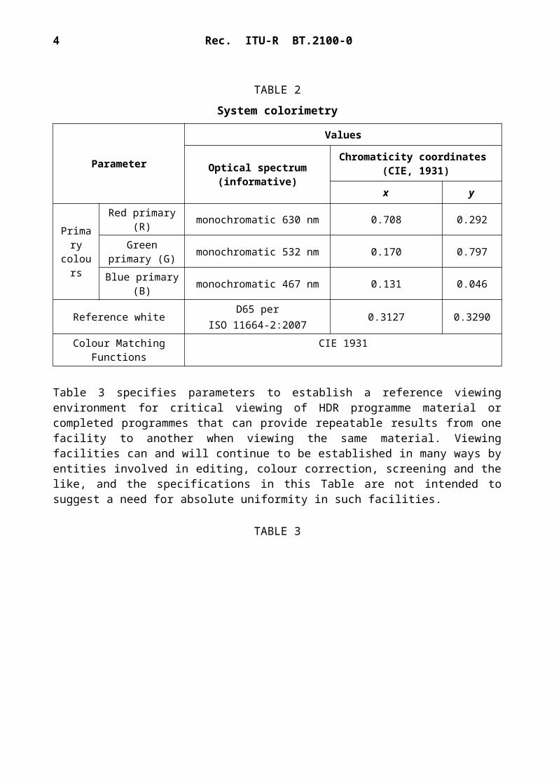
TABLE 2
System colorimetry
Parameter
Values
Optical spectrum (informative)
Chromaticity coordinates (CIE, 1931)
x y
Primary colours
Red primary (R) monochromatic 630 nm 0.708 0.292Green primary
(G) monochromatic 532 nm 0.170 0.797
Blue primary (B) monochromatic 467 nm 0.131 0.046
Reference whiteD65 per
ISO 11664-2:20070.3127 0.3290
Colour Matching Functions CIE 1931
Table 3 specifies parameters to establish a reference viewing environment for critical viewing of HDR programme material or completed programmes that can provide repeatable results from one facility to another when viewing the same material. Viewing facilities can and will continue to be established in many ways by entities involved in editing, colour correction, screening and the like, and the specifications in this Table are not intended to suggest a need for absolute uniformity in such facilities.
TABLE 3
4 Rec. ITU-R BT.2100-0
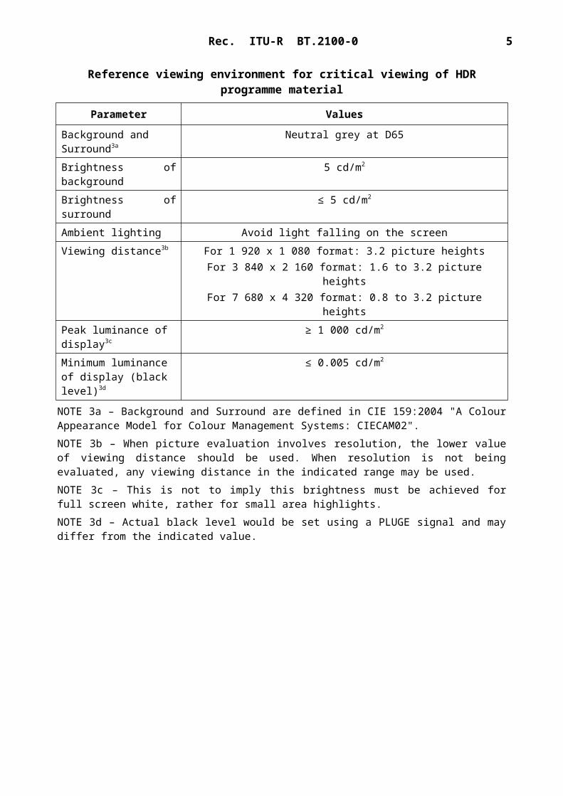
Reference viewing environment for critical viewing of HDR programme material
Parameter Values
Background and Surround3a
Neutral grey at D65
Brightness of background 5 cd/m2
Brightness of surround ≤ 5 cd/m2
Ambient lighting Avoid light falling on the screenViewing distance3b For 1 920 x 1 080 format: 3.2 picture heights
For 3 840 x 2 160 format: 1.6 to 3.2 picture heightsFor 7 680 x 4 320 format: 0.8 to 3.2 picture heights
Peak luminance of display3c
≥ 1 000 cd/m2
Minimum luminance of display (black level)3d
≤ 0.005 cd/m2
NOTE 3a – Background and Surround are defined in CIE 159:2004 "A Colour Appearance Model for Colour Management Systems: CIECAM02".NOTE 3b – When picture evaluation involves resolution, the lower value of viewing distance should be used. When resolution is not being evaluated, any viewing distance in the indicated range may be used.NOTE 3c – This is not to imply this brightness must be achieved for full screen white, rather for small area highlights. NOTE 3d – Actual black level would be set using a PLUGE signal and may differ from the indicated value.
Rec. ITU-R BT.2100-0 5
Tables 4 and 5 describe transfer functions for the PQ and HLG formats, respectively. High dynamic range television production and display should make consistent use of the transfer functions of one system or the other and not intermix them. Informative Annex 1 illustrates the meaning of the various transfer functions and where they are used in the signal chain. Informative Annex 3 provides information on alternate equations that could facilitate implementation of these transfer functions.
TABLE 4
PQ system reference non-linear transfer functions
Parameter Values
Input signal to PQ electro-optical transfer function (EOTF)
Non-linear PQ encoded value.The EOTF maps the non-linear PQ signal into display light.
Reference PQ EOTF4a
FD=EOTF [ E' ]=10000 Y
Y=(max [ ( E¿−c1 ) ,0 ]c2−c3 E¿ )
1/m1
where:E' denotes a non-linear colour value {R', G', B'} or { L', M', S'} in PQ space [0,1]FD is the luminance of a displayed linear component {RD, GD, BD} or YD or ID, in cd/m2. 4b
So that when R'=G'=B', the displayed pixel is achromatic. Y denotes the normalized linear colour value, in the range [0:1] m1 = 2610/16384 = 0.1593017578125 m2 = 2523/4096 128 = 78.84375 c1 = 3424/4096 =0.8359375 = c3 − c2 + 1c2 = 2413/4096 32 = 18.8515625c3 = 2392/4096 32 = 18.6875
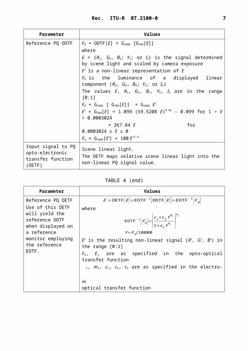
Input signal to PQ opto-optical transfer function (OOTF)
Scene linear light.The OOTF maps relative scene linear light to display linear light.
Reference PQ OOTF FD = OOTF[E] = G1886 [G709[E]] where E = {RS, GS, BS; YS; or IS} is the signal determined by scene light and scaled by camera exposureE′ is a non-linear representation of EFD is the luminance of a displayed linear component (RD, GD, BD; YD; or ID)The values E, RS, GS, BS, YS, IS are in the range [0:1]FD = G1886 [ G709[E]] = G1886 E′ E′ = G709[E] = 1.099 (59.5208 E)0.45 – 0.099 for 1 > E > 0.0003024
= 267.84 E for 0.0003024 ≥ E ≥ 0FD = G1886[E'] = 100 E′ 2.4
Input signal to PQ opto-electronic transfer function (OETF)
Scene linear light.The OETF maps relative scene linear light into the non-linear PQ signal value.
6 Rec. ITU-R BT.2100-0
TABLE 4 (end)
Parameter Values
Reference PQ OETFUse of this OETF will yield the reference OOTF when displayed on a reference monitor employing the reference EOTF.
E'=OETF [ E ]=EOTF−1 [OOTF [E ] ]=EOTF−1 [ F D ]where
EOTF−1 [F D ]=(c1+c2 Ym1
1+c3Y m1 )m2
Y=F D/10000E′ is the resulting non-linear signal (R', G', B') in the range [0:1]FD, E, are as specified in the opto-optical transfer function
m
1, m2, c1, c2, c3 are as specified in the electro-optical transfer function
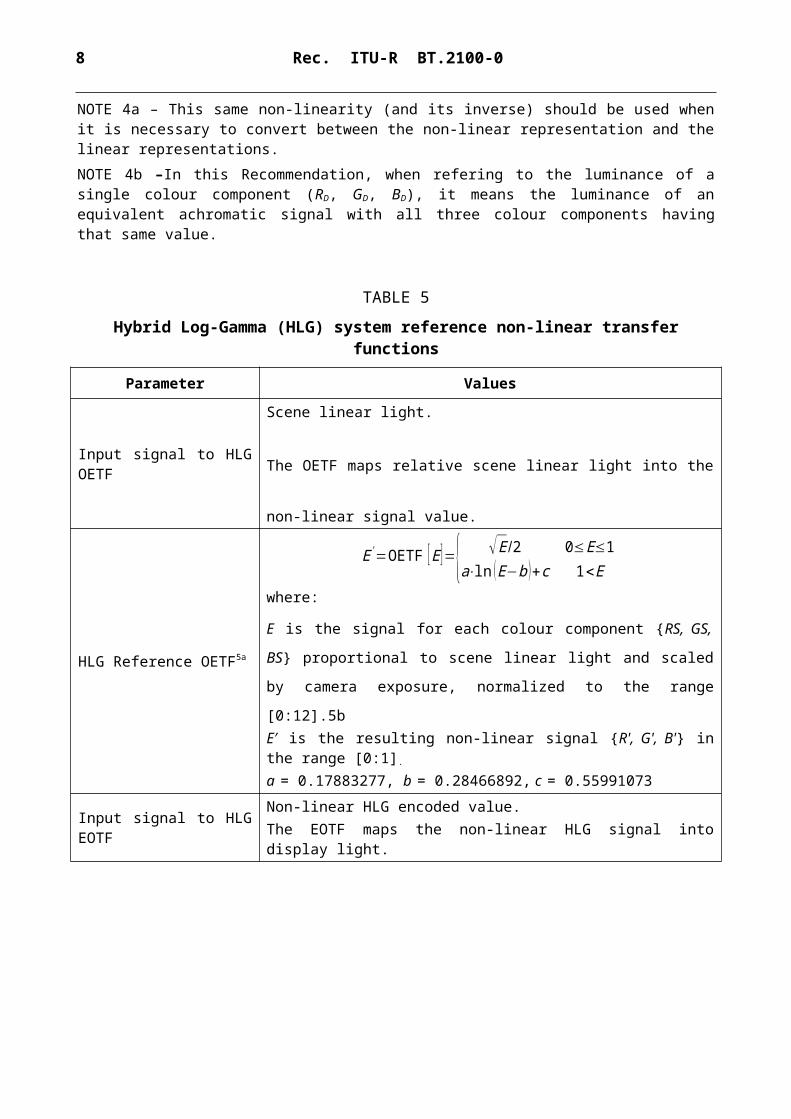
NOTE 4a – This same non-linearity (and its inverse) should be used when it is necessary to convert between the non-linear representation and the linear representations.NOTE 4b –In this Recommendation, when refering to the luminance of a single colour component (RD, GD, BD), it means the luminance of an equivalent achromatic signal with all three colour components having that same value.
TABLE 5
Hybrid Log-Gamma (HLG) system reference non-linear transfer functions
Parameter Values
Input signal to HLG OETFScene linear light.
The OETF maps relative scene linear light into the non-linear signal value.
HLG Reference OETF5a
E'=OETF [ E ]={ √ E/2 0≤E≤1a⋅ln ( E−b )+c 1<E
where:
E is the signal for each colour component {RS, GS, BS} proportional to
scene linear light and scaled by camera exposure, normalized to the range
[0:12].5bE′ is the resulting non-linear signal {R', G', B'} in the range [0:1].
a = 0.17883277, b = 0.28466892, c = 0.55991073
Input signal to HLG EOTFNon-linear HLG encoded value.The EOTF maps the non-linear HLG signal into display light.
Rec. ITU-R BT.2100-0 7
TABLE 5 (cont.)
Parameter Values
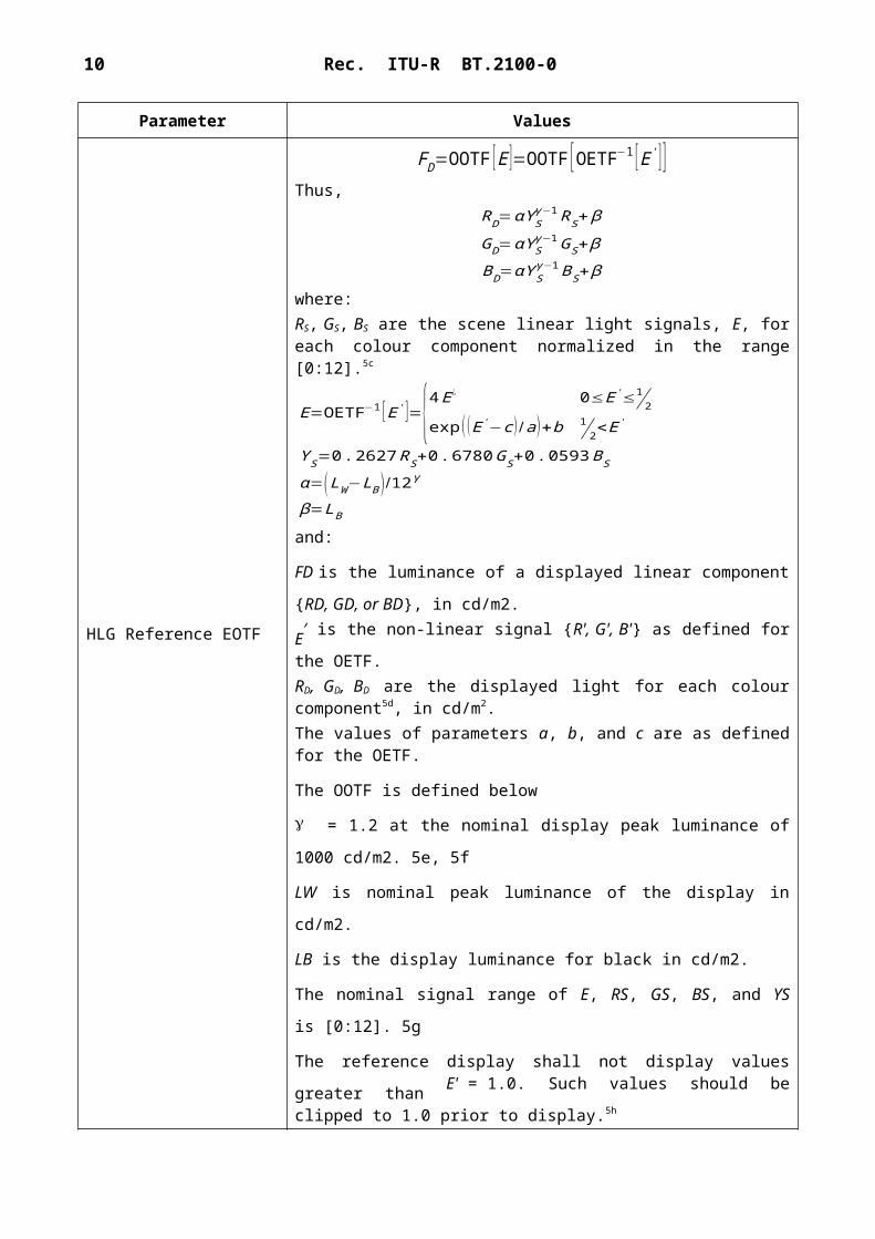
HLG Reference EOTF
FD=OOTF [ E ]=OOTF [ OETF−1 [ E' ] ]Thus,
RD=αY Sγ −1 RS+β
GD=αY Sγ −1 GS+β
BD=αY Sγ−1 BS+β
where:RS, GS, BS are the scene linear light signals, E, for each colour component normalized in the range [0:12].5c
E=OETF−1 [ E' ]={4 E¿ 0≤E '≤12
exp ( ( E'−c ) /a)+b 12<E '
Y S=0 .2627 RS+0. 6780 GS+0 . 0593 BS
α=(LW −LB ) /12γ
β=LB
and:
FD is the luminance of a displayed linear component {RD, GD, or BD}, in
cd/m2.
E′ is the non-linear signal {R', G', B'} as defined for the OETF.
RD, GD, BD are the displayed light for each colour component5d, in cd/m2. The values of parameters a, b, and c are as defined for the OETF.
The OOTF is defined below
= 1.2 at the nominal display peak luminance of 1000 cd/m2. 5e, 5f
LW is nominal peak luminance of the display in cd/m2.
LB is the display luminance for black in cd/m2.
The nominal signal range of E, RS, GS, BS, and YS is [0:12]. 5g
The reference display shall not display values greater than E' = 1.0. Such
values should be clipped to 1.0 prior to display.5h
HLG Input signal to OOTF Scene linear light.The OOTF maps relative scene linear light to display linear light.
8 Rec. ITU-R BT.2100-0
TABLE 5 (end)
Parameter Values
HLG Reference OOTF
FD=OOTF [ E ]=αY Sγ−1 E+β
RD=αY Sγ −1 RS+ β
GD=αY Sγ−1GS+β
BD=αY Sγ −1 BS+β
Y s=0 . 2627 RS+0 .6780GS+0 .0593 BS
where:
FD is the luminance of a displayed linear component {RD, GD, or BD}, in
cd/m2.
E is the signal for each colour component {Rs, Gs, Bs} proportional to
scene linear light and scaled by camera exposure, normalized to the range
[0:12].
YS is the normalized linear scene luminance.
α, β, and γ are as defined for the EOTF.
NOTE 5a – The inverse of this non-linearity should be used when it is necessary to convert between the non-linear representation and the linear representation of scene light.NOTE 5b – If E is normalized to the range [0:1] then the equivalent equation for the OETF is:
E'=OETF [ E ]={ √3 E 0≤E≤112
a⋅ln ( E−b )+c 112<E
where a = 0.17883277, b = 0.02372241, c = 1.00429347NOTE 5c – If E is normalized to the range [0:1] then the equivalent equation for the E is:
E=OETF−1 [ E' ]={ E¿ /3 0≤E '≤12
exp (( E '−c )/a)+b 12<E'
where a, b and c are as defined in Note 5b.NOTE 5d – This EOTF applies gamma to the luminance component of the signal, whereas some legacy displays may apply gamma separately to colour components. Such legacy displays approximate this reference OOTF.NOTE 5e – For displays with nominal peak luminance (LW) greater than 1000 cd/m2, or where the effective nominal peak luminance is reduced through the use of a contrast control, the system gamma value should be adjusted according to the formula below, and may be rounded to three significant digits:
γ=1 . 2+0 . 42Log10 (LW /1000 )NOTE 5f – The system gamma value may be decreased for brighter background and surround conditions.NOTE 5g – When E is normalized to the range [0:1] then the equation for α is:
α=(LW −LB )NOTE 5h – During production, signal values are expected to exceed the range E′ = [0.0 : 1.0]. This provides processing headroom and avoids signal degradation during cascaded processing. Such values of E′, below 0.0 or exceeding 1.0, should not be clipped during production and exchange. Values exceeding 1.0 should not be shown on reference displays. Values below 0.0 should not be clipped in reference displays (even though they
Rec. ITU-R BT.2100-0 9
represent “negative” light) to allow the black level of the signal (LB) to be properly set using test signals known as “PLUGE” (see Recommendation ITU-R BT.814).
Tables 6 and 7 describe different luminance and colour difference signal representations, suitable for colour sub-sampling, and/or source coding. The Non-Constant Luminance (NCL) format is in widespread use and is considered the default. The Constant Intensity (CI) format is newly introduced in this Recommendation and should not be used for programme exchange unless all parties agree.
TABLE 6
Non-Constant Luminance Y'C'BC'R signal format6a
Parameter Values PQ Values HLG
Derivation of R', G', B' {R', G', B'}=EOTF−1(FD)where FD = {RD, GD, BD}
{R', G', B'}=OETF(E)where E = {RS, GS, BS}
Derivation of Y' Y' = 0.2627R' + 0.6780G' + 0.0593B'
Derivation of colour difference signals
4746.1
8814.1Y'R'C
Y'B'C
R
B
N
OTE 6a – For consistency with prior use of terms, Y', C'B and C'R employ prime symbols indicating
they have come from non-linear Y, B and R.
TABLE 7
Constant Intensity ICTCP signal format7a, 7b
Parameter Values PQ Values HLG
L, M, S Colour Space L=(1688 R+2146 G+262 B )/4096M=(683 R+2951 G+462 B ) /4096S= ( 99 R+ 309G+3688 B ) /4096
CT=(6610 L'−13613 M'+7003 S' )/4096CP= (17933 L'−17390 M' −543 S' ) /4096
NOTE 7a – The newly introduced I, CT and CP symbols do not employ the prime symbols to simplify the notation.NOTE 7b –Colours should be constrained to be within the triangle defined by the RGB colour primaries in Table 2.
10 Rec. ITU-R BT.2100-0
NOTE 7c – The subscripts D and S refer to display light and scene light, respectively.
TABLE 8
Colour sub-sampling
Parameters Values
Coded signal R', G', B' or Y', C'B, C'R, , or I, CT, CP
Sampling lattice– R', G', B', Y', I
Orthogonal, line and picture repetitive co-sited
Sampling lattice– C'B, C'R, CT, CP
Orthogonal, line and picture repetitive co-sited with each other.The first (top-left) sample is co-sited with the first Y' or I samples.4:4:4 system 4:2:2 system 4:2:0 system
Each has the same number of horizontal samples as the Y' or I
component.
Horizontally subsampled by a factor of two with respect to the Y' or I component.
Horizontally and vertically subsampled
by a factor of two with respect to the Y'
or I component.
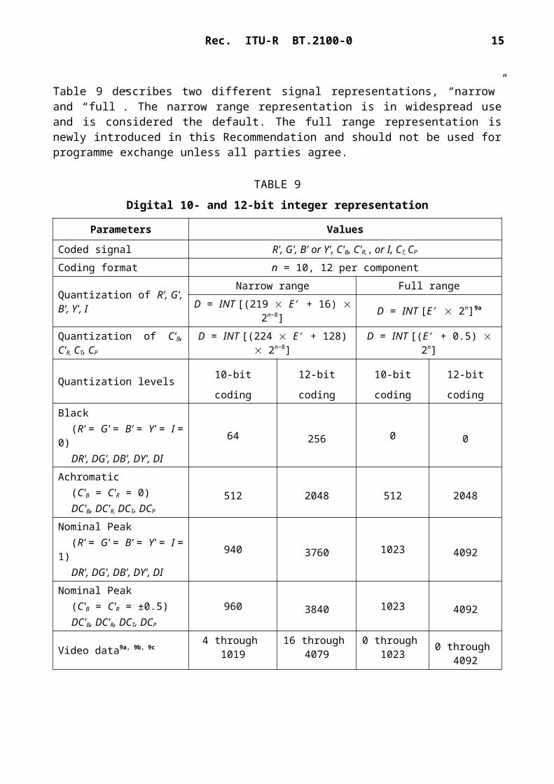
Table 9 describes two different signal representations, “narrow” and “full”. The narrow range representation is in widespread use and is considered the default. The full range representation is newly introduced in this Recommendation and should not be used for programme exchange unless all parties agree.
TABLE 9
Digital 10- and 12-bit integer representation
Parameters Values
Coded signal R', G', B' or Y', C'B, C'R, , or I, CT, CP
Coding format n = 10, 12 per component
Quantization of R', G', B', Y', I
Narrow range Full rangeD = INT [(219 E′ + 16) 2n−8] D = INT [E′ 2n]9a
Quantization of C'B, C'R, CT, CP
D = INT [(224 E′ + 128) 2n−8] D = INT [(E′ + 0.5) 2n]
NOTE 9a – 10-bit values of E > 1023/1024 cannot be represented. For consistency, 12-bit values are thus clipped to the value 4092/4096. NOTE 9b – Signals may extend below black (sub-blacks) and exceed the nominal peak values (super-whites), but shall not exceed the video data range.NOTE 9c – Narrow range values outside of the video data range are used for timing signals on some interfaces, and thus should not be used. Full range signals may be clipped to the narrow video data range when conveyed over such interfaces.
Table 10 introduces a 16-bit floating point signal representation. Currently, real-time interfaces do not exist for this format. It is expected that this format would initially see usage in file-based workflows and programme exchange.
TABLE 10
Floating Point (FP) signal representation
Parameter ValuesSignal representation Linear R, G, B.Signal encoding 16-bit floating point per IEEE standard 754-2008.Normalization for PQ A value of 1.0 for each of R, G, B yields 1.0 cd/m2
on the reference display.Normalization for HLG A value of 1.0 represents nominal peak white of the signal.
Annex 1(Informative)
The relationship between the OETF, the EOTF and the OOTF
This Recommendation makes extensive use of the following terms:OETF: the opto-electronic transfer function, which converts linear scene light into the video signal,
typically within a camera.EOTF: electro-optical transfer function, which converts the video signal into the linear light output
of the display.OOTF: opto-optical transfer function, which has the role of applying the “rendering intent”.
These functions are related, so only two of the three are independent. Given any two of them the third one may be calculated. This section explains how they arise in television systems and how they are related.
In television systems the displayed light is not linearly related to the light captured by the camera. Instead an overall non-linearity is applied, the OOTF. The “reference” OOTF compensates for difference in tonal perception between the environment of the camera and that of the display.
12 Rec. ITU-R BT.2100-0
Specification and use of a “reference OOTF” allows consistent end-to-end image reproduction, which is important in TV production.
Artistic adjustment may be made to enhance the picture. These alter the OOTF, which may then be called the “artistic OOTF”. Artistic adjustment may be applied either before or after the reference OOTF.
In general the OOTF is a concatenation of the OETF, artistic adjustments, and the EOTF.
The PQ system was designed with the model shown below, where the OOTF is considered to be in the camera (or imposed in the production process).
Rec. ITU-R BT.2100-0 13
The HLG system was designed with the model shown below, where the OOTF is considered to be in the display.
Only two of three non-linearities, the OETF, the EOTF, and the OOTF, are independent. In functional notation (where subscripts indicate the colour component):
OOTFR ( R , G , B )=EOTFR (OETFR ( R ,G , B ) )OOTFG ( R ,G , B )=EOTFG (OETFG (R , G , B ))OOTFB ( R , G, B )=EOTFB (OETFB ( R , G , B ) )
This is clearer if the concatenation is represented by the symbol . With this notation, the following three relationships between these three non-linearities are obtained:
OOTF=OETF⊗EOTFEOTF=OETF−1⊗OOTFOETF=OOTF⊗EOTF−1
OOTF−1=EOTF−1⊗OETF−1
EOTF−1=OOTF−1⊗OETFOETF−1=EOTF⊗OOTF−1
The PQ approach is defined by its EOTF. For PQ, the OETF may be derived from the OOTF using the third line of the equations above. In a complementary fashion the HLG approach is defined by its OETF. For HLG, the EOTF may be derived from the OOTF using the second line of the equations above.
14 Rec. ITU-R BT.2100-0
Annex 2(Informative)
Conversion between HLG and PQ signals
The following diagram illustrates conversion from the PQ signal to the HLG signal. The signal processing is that the PQ signal is decoded by the PQ EOTF to yield a signal that represents linear display light. This signal is then encoded by the HLG inverse EOTF to produce an equivalent HLG signal. When this HLG signal is subsequently decoded by the HLG EOTF in the display, the result will be the same display light that would be produced by decoding the original PQ signal with the PQ EOTF. The HLG inverse EOTF is the HLG inverse OOTF followed by the HLG OETF. For the HLG inverse OOTF, black level should be zero, and the gamma parameter is determined by the peak level of the PQ signal.
The following diagram illustrates conversion from the HLG signal to the PQ signal. The signal processing is that the HLG signal is decoded by the HLG EOTF to yield a signal that represents linear display light. This signal is then encoded by the PQ inverse EOTF to produce an equivalent PQ signal. When this PQ signal is subsequently decoded by the PQ EOTF in the display, the result will be the same display light that would be produced by decoding the original HLG signal with the HLG EOTF. For the HLG EOTF, black level should be zero, and the gamma may be set to the value specified in Table 5 (presuming peak luminance of 1 000 cd/m2).
Rec. ITU-R BT.2100-0 15
Annex 3(Informative)
Parametric representation of electro-optical and opto-electronic transfer functions
This Annex in connection with appropriate parameter sets facilitates the implementation of the reference opto-electronic transfer functions (OETFs), as well as the reference electro-optical transfer functions (EOTFs) of this Recommendation.
An EOTF may be represented by equation (1):
L (V )=( c−(V−m ) stV−m−s )
1/n
(1)
where:
V : nonlinear colour valueL : corresponding linear colour value.
The parameter set {s, t, c, n, m} can be set according to a desired application.
An OETF may be represented by equation (2):
V ( L )= sLn+cLn+st
+m(2)
It should be noted that if the parameters s, t, c, n and m are given identical values in equations (1) and (2), then L(V ) and V (L) are the mathematical inverse of each other.
In certain applications, it is helpful to normalize V in equations (1) and (2) according to equation (3):
V̂=V−pk
+m(3)
where:V : non-linear colour value
V̂ : normalized non-linear colour value that replaces V in equations (1) and (2).
The parameters k and p can be set according to a desired application.
In certain applications, it is helpful to normalize L in equations (1) and (2) according to equation (4):
L̂= L−ba (4)
where:L : linear colour value
L̂ : normalized linear colour value that replaces L in equations (1) and (2).
16 Rec. ITU-R BT.2100-0
The parameters a and b can be set according to a desired application.