34
Recommendation ITU-R BT.1365-2 (10/2015) 24-bit digital audio format as ancillary data signals in HDTV and UHDTV serial interfaces BT Series Broadcasting service (television)
Recommendation ITU-R BT.1365-2(10/2015)
24-bit digital audio format as ancillary data signals in HDTV and UHDTV serial
interfaces
BT SeriesBroadcasting service
(television)
ii Rec. ITU-R BT.1365-2
Foreword
The role of the Radiocommunication Sector is to ensure the rational, equitable, efficient and economical use of the radio-frequency spectrum by all radiocommunication services, including satellite services, and carry out studies without limit of frequency range on the basis of which Recommendations are adopted.
The regulatory and policy functions of the Radiocommunication Sector are performed by World and Regional Radiocommunication Conferences and Radiocommunication Assemblies supported by Study Groups.
Policy on Intellectual Property Right (IPR)
ITU-R policy on IPR is described in the Common Patent Policy for ITU-T/ITU-R/ISO/IEC referenced in Annex 1 of Resolution ITU-R 1. Forms to be used for the submission of patent statements and licensing declarations by patent holders are available from http://www.itu.int/ITU-R/go/patents/en where the Guidelines for Implementation of the Common Patent Policy for ITU-T/ITU-R/ISO/IEC and the ITU-R patent information database can also be found.
Series of ITU-R Recommendations (Also available online at http://www.itu.int/publ/R-REC/en)
Series Title
BO Satellite deliveryBR Recording for production, archival and play-out; film for televisionBS Broadcasting service (sound)BT Broadcasting service (television)F Fixed serviceM Mobile, radiodetermination, amateur and related satellite servicesP Radiowave propagationRA Radio astronomyRS Remote sensing systemsS Fixed-satellite serviceSA Space applications and meteorologySF Frequency sharing and coordination between fixed-satellite and fixed service systemsSM Spectrum managementSNG Satellite news gatheringTF Time signals and frequency standards emissionsV Vocabulary and related subjects
Note: This ITU-R Recommendation was approved in English under the procedure detailed in Resolution ITU-R 1.
Electronic PublicationGeneva, 2015
ITU 2015
All rights reserved. No part of this publication may be reproduced, by any means whatsoever, without written permission of ITU.
Rec. ITU-R BT.1365-2 1
RECOMMENDATION ITU-R BT.1365-2
24-bit digital audio format as ancillary data signalsin HDTV and UHDTV serial interfaces
(Question ITU-R 130/6)
(1998-2010-2015)
Scope
This Recommendation defines the mapping of 24-bit digital audio data conforming with Recommendation ITU-R BS.647 and associated control information into the ancillary data space of serial digital video interfaces conforming to Recommendation ITU-R BT.1120 and Recommendation ITU-R BT.2077. The audio data are derived from Recommendation ITU-R BS.647, hereafter referred to as Audio Engineering Society (AES).
Keywords
UHDTV, Serial Interface, AES bit stream
The ITU Radiocommunication Assembly,
considering
a) that many countries are installing digital HDTV and UHDTV production facilities based on the use of digital video components conforming to Recommendations ITU-R BT.709, ITU-R BT.2020, ITU-R BT.1120 and ITU-R BT.2077;
b) that there exists the capacity within the serial digital interface for HDTV and UHDTV for additional data signals to be multiplexed as part of the serial data stream;
c) that there are operational and economic benefits to be achieved by the multiplexing of ancillary data signals along with the video data signal;
d) that audio is one of the most important uses of the ancillary data packets;
e) that audio data may need error correction codes to keep the balance between audio quality and video quality because errors in audio data are more easily noticed than those of video data;
f) that audio equipment with 24-bit accuracy is commonly used in production facilities;
g) that some broadcasters have the need to transmit asynchronous audio data by multiplexing into the serial digital interface,
recommends
1 that, for the inclusion of 24-bit digital audio format as ancillary data signals in HDTV and UHDTV serial interfaces, the specification described in Annex 1 and or Annex 2 of this Recommendation should be used;
2 that compliance with this Recommendation is voluntary. However, the Recommendation may contain certain mandatory provisions (to ensure e.g. interoperability or applicability) and compliance with the Recommendation is achieved when all of these mandatory provisions are met.
2 Rec. ITU-R BT.1365-2
Definition of terms
Definition of these terms applies to the usage made in this Recommendation.
AES audio: All the VUCP (sample validity bit (V), user data bit (U), channel status bit (C), even parity bit (P)) data, audio data and auxiliary data, associated with one AES digital stream as defined in Recommendation ITU-R BS.647.
AES frame: Two AES subframes; in the case of the 32 kHz to 48 kHz sampling subframes one and two carry AES audio channel 1 and 2 respectively. In the case of 96 kHz sampling subframes one and two carry successive samples of the same AES audio signal which is mandatory for 96 kHz application.
AES subframe: All data associated with one AES audio sample for one channel in a channel pair.
audio control packet: An ancillary data packet occurring once a field in an interlaced system and once a frame in a progressive system and containing data used in the process of decoding the audio data stream.
audio clock phase data: Audio clock phase is indicated by the number of video clocks between the first word of EAV and the video sample at the same timing when audio sample appeared at the input to the formatter.
audio data: 29 bits: 24 bits of AES audio associated with one audio sample, including AES auxiliary data, plus VUCP bits and the Z flag which is derived from the preamble of AES3 stream. The Z bit is common to the two channels of an AES channel pair.
error correction code: BCH (31, 25) code (an error correction method) in each bit sequence of b0-b7. Errors between the first word of ancillary data flag (ADF) through the last word of audio data of channel 4 (CH4) in user data words (UDW) will be corrected or detected within the capability of this code.
audio data packet: An ancillary data packet containing audio clock phase data, audio data for two channel pairs (4 channels) and error correction code. An audio data packet should contain audio data of one sample associated with each audio channel.
audio frame number: A number, starting at 1, for each frame within the audio frame sequence.
audio frame sequence: The number of video frames required for an integer number of audio samples in isochronous operation.
audio group: Consists of two channel pairs that are contained in one ancillary data packet. Each audio group has a unique ID. Audio groups are numbered 1 through 4.
channel pair: Two digital audio channels, derived from the same AES audio source.
data ID: A word in the ancillary data packet which identifies the use of the data therein.
Extended audio group: an audio group as defined in Annex 1 of this Recommendation, but numbered from 5 to 8.
Extended audio data packet: an audio data packet as defined in Annex 1 of this Recommendation, but with identity corresponding to Extended audio group numbers 5 to 8.
Extended audio control packet: an audio control packet defined in Annex 1 of this Recommendation, but with identity corresponding to Extended audio group numbers 5 to 8.
horizontal ancillary data block: An ancillary data space located in the digital line blanking interval of one television line.
Rec. ITU-R BT.1365-2 3
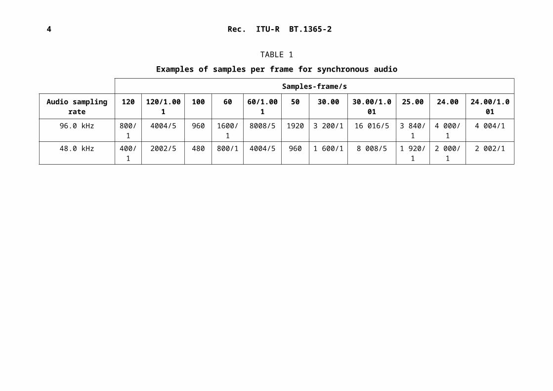
isochronous audio: Audio is defined as being clock isochronous with video if the sampling rate of audio is such that the number of audio samples occurring within an integer number of video frames is itself a constant integer number, as shown in the following example:
4 Rec. ITU-R BT.1365-2
TABLE 1
Examples of samples per frame for synchronous audio
Samples-frame/sAudio sampling
rate120 120/1.00
1100 60 60/1.00
150 30.00 30.00/1.0
0125.00 24.00 24.00/1.0
0196.0 kHz 800/
14004/5 960 1600/
18008/5 1920 3 200/1 16 016/5 3 840/
14 000/1 4 004/1
48.0 kHz 400/1
2002/5 480 800/1 4004/5 960 1 600/1 8 008/5 1 920/1
2 000/1 2 002/1
Rec. ITU-R BT.1365-2 5
Annex 1
24-bit digital audio format as ancillary data signalsin HDTV and UHDTV serial interfaces
1 Introduction
Audio sampled at a clock frequency of 48 kHz locked (synchronous) to video is the preferred implementation for intrastudio applications. As an option, this Recommendation supports Audio Engineering Society (AES) audio at synchronous or asynchronous sampling rates from 32 kHz to 48 kHz and 96 kHz. Audio channels are transmitted in groups of four, up to a maximum of 16 audio channels in the case of 32 kHz, 44.1 kHz or 48 kHz sampling, and up to a maximum of 8 audio channels in case of 96 kHz sampling. Each group is identified by a unique ancillary data ID.
Audio data packets are multiplexed (embedded) into the horizontal ancillary data space of the C'B/C'R data stream, and audio control packets are multiplexed into the horizontal ancillary data space of the Y data stream. The multiplexed data are converted into serial form according to the HDTV serial digital interfaces defined in Recommendation ITU-R BT.1120.
For UHDTV interfaces conforming to Recommendation ITU-R BT. 2077 Parts 1 and 3, this Recommendation applies to Y data stream and C'B/C'R data stream, making up the overall multiplex.
For UHDTV interfaces conforming to Recommendation ITU-R BT.2077 Part 2, this Recommendation applies to basic stream 1 and basic stream 2 of the interface according to §§ 3.5 and 3.6 in Part 2 of Recommendation ITU-R BT.2077.
2 References– Recommendation ITU-R BT.709 – Parameter Values for the HDTV standards for
production and international programme exchange.– Recommendation ITU-R BT.1120 – Digital interfaces for HDTV studio signals.– Recommendation ITU-R BS.647 – A Digital audio interface for broadcasting studios.– Recommendation ITU-R BT.2020- Parameter values for ultra-high definition television
systems for production and international programme exchange.– Recommendation ITU-R BT.2077– Real-time serial digital interfaces for UHDTV signals.– Recommendation ITU-R BT.1364 – Format of Ancillary Data signals carried in digital
component studios.
3 Overview
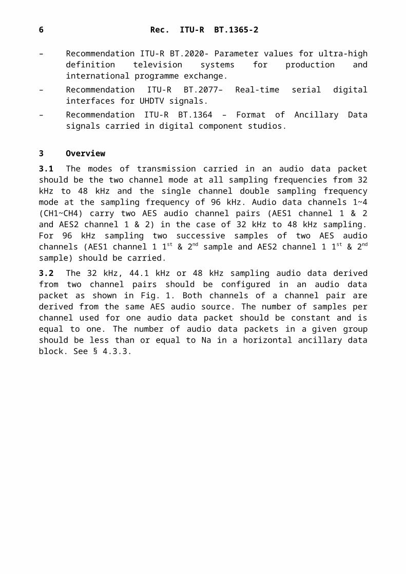
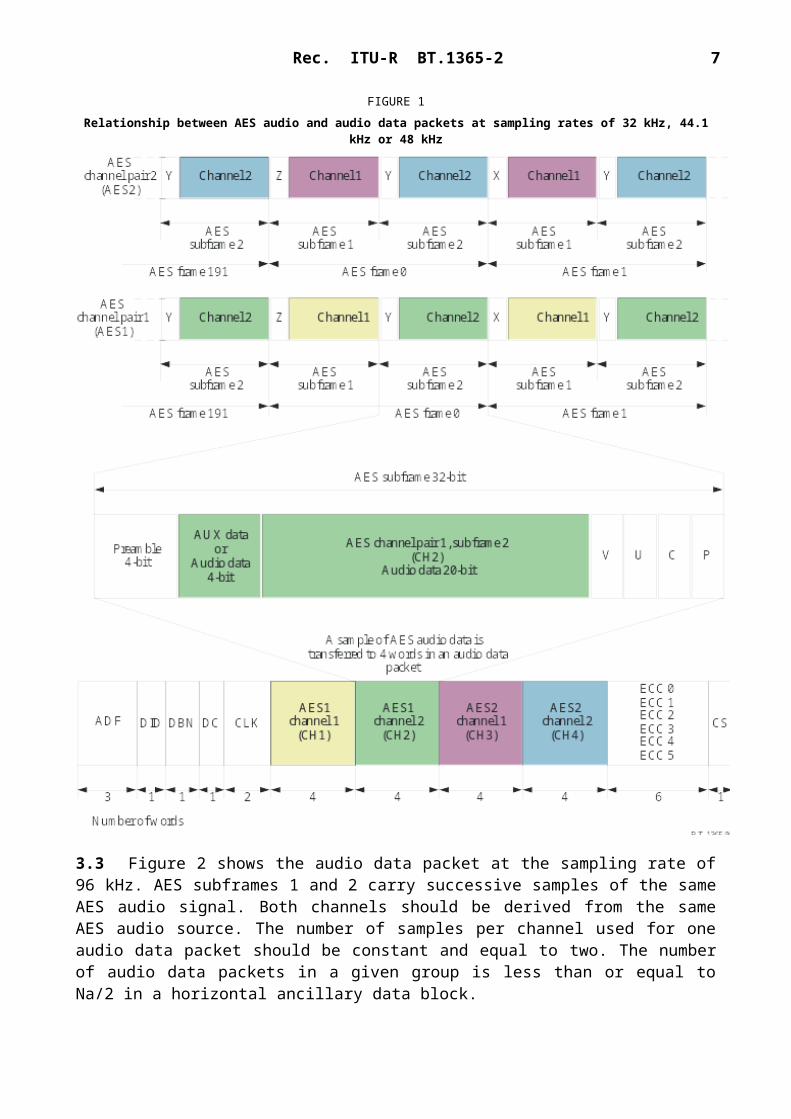
3.1 The modes of transmission carried in an audio data packet should be the two channel mode at all sampling frequencies from 32 kHz to 48 kHz and the single channel double sampling frequency mode at the sampling frequency of 96 kHz. Audio data channels 1~4 (CH1~CH4) carry two AES audio channel pairs (AES1 channel 1 & 2 and AES2 channel 1 & 2) in the case of 32 kHz to 48 kHz sampling. For 96 kHz sampling two successive samples of two AES audio channels (AES1 channel 1 1st & 2nd sample and AES2 channel 1 1st & 2nd sample) should be carried.
3.2 The 32 kHz, 44.1 kHz or 48 kHz sampling audio data derived from two channel pairs should be configured in an audio data packet as shown in Fig. 1. Both channels of a channel pair are derived from the same AES audio source. The number of samples per channel used for one audio
6 Rec. ITU-R BT.1365-2
data packet should be constant and is equal to one. The number of audio data packets in a given group should be less than or equal to Na in a horizontal ancillary data block. See § 4.3.3.
FIGURE 1Relationship between AES audio and audio data packets at sampling rates of 32 kHz, 44.1 kHz
or 48 kHz
3.3 Figure 2 shows the audio data packet at the sampling rate of 96 kHz. AES subframes 1 and 2 carry successive samples of the same AES audio signal. Both channels should be derived from the same AES audio source. The number of samples per channel used for one audio data packet should be constant and equal to two. The number of audio data packets in a given group is less than or equal to Na/2 in a horizontal ancillary data block.
Rec. ITU-R BT.1365-2 7
FIGURE 2Relationship between AES audio and audio data packets at a sampling rate of 96 kHz
3.4 Two types of ancillary data packets carrying AES audio information are defined in this Recommendation. Each audio data packet should carry all of the information in the AES bit stream. The audio data packet should be located in the horizontal ancillary data space of the C'B/C'R data stream. An audio control packet should be transmitted once per field in an interlaced system and once per frame in a progressive system in the horizontal ancillary data space of the second line after the switching point of the Y data stream.
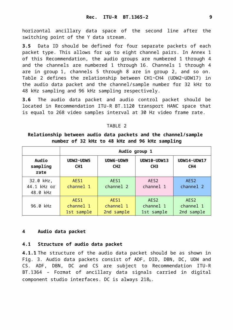
3.5 Data ID should be defined for four separate packets of each packet type. This allows for up to eight channel pairs. In Annex 1 of this Recommendation, the audio groups are numbered 1 through 4 and the channels are numbered 1 through 16. Channels 1 through 4 are in group 1, channels 5 through 8 are in group 2, and so on. Table 2 defines the relationship between CH1~CH4
8 Rec. ITU-R BT.1365-2
(UDW2~UDW17) in the audio data packet and the channel/sample number for 32 kHz to 48 kHz sampling and 96 kHz sampling respectively.
3.6 The audio data packet and audio control packet should be located in Recommendation ITU-R BT.1120 transport HANC space that is equal to 268 video samples interval at 30 Hz video frame rate.
TABLE 2
Relationship between audio data packets and the channel/sample number of 32 kHz to 48 kHz and 96 kHz sampling
Audio group 1
Audio sampling rate
UDW2~UDW5 CH1
UDW6~UDW9 CH2
UDW10~UDW13 CH3
UDW14~UDW17 CH4
32.0 kHz, 44.1 kHz or
48.0 kHz
AES1 channel 1
AES1 channel 2
AES2 channel 1
AES2 channel 2
96.0 kHzAES1
channel 11st sample
AES1 channel 1
2nd sample
AES2 channel 11st sample
AES2 channel 1
2nd sample
4 Audio data packet
4.1 Structure of audio data packet
4.1.1 The structure of the audio data packet should be as shown in Fig. 3. Audio data packets consist of ADF, DID, DBN, DC, UDW and CS. ADF, DBN, DC and CS are subject to Recommendation ITU-R BT.1364 – Format of ancillary data signals carried in digital component studio interfaces. DC is always 218h.
FIGURE 3Structure of audio data packets

Rec. ITU-R BT.1365-2 9
4.1.2 DID is defined as 2E7h for audio group 1 (channel 1-4), 1E6h for audio group 2 (channel 5-8), 1E5h for audio group 3 (channel 9-12) and 2E4h for audio group 4 (channel 13-16), respectively.
4.1.3 UDW is defined in § 4.2. In this Recommendation, UDWx means the Xth user data word. There are always 24 words in the UDW of an audio data packet, i.e. UDW0, UDW1, …, UDW22, UDW23.
4.1.4 All audio channels in a given audio group should have identical sampling rate, identical sampling phase and identical isochronous/asynchronous status.
4.1.5 For a given audio data packet, one sample of the audio data of each channel (CH1-CH4) is always transmitted. Even when only one of the four channels (CH1-CH4) is active, all audio data of the four channels should be transmitted. In such case, the value of audio data, V, U, C and P bits of all inactive channels should be set to zero.
4.2 Structure of user data words
UDW consists of three types of data defined in §§ 4.2.1 to 4.2.3. The description in this clause covers only audio group 1. The description for audio groups 2, 3 and 4 is similar to that for audio group 1 where channels 5, 9 and 13 correspond to channel 1, channels 6, 10 and 14 correspond to channel 2, channels 7, 11 and 15 correspond to channel 3, channels 8, 12 and 16 correspond to channel 4, respectively.
4.2.1 Audio clock phase data
4.2.1.1 Audio clock phase data (CLK) is used to regenerate audio sampling clock at the receiving side, especially for asynchronous audio. Bit-assignment of CLK should be as shown in Table 3.
TABLE 3
Bit assignment of CLK
Bit number UDW0 UDW1b9 (MSB)b8b7b6b5b4b3b2b1b0 (LSB)
Not b8Even parity(1)
ck7 audio clock phase datack6 audio clock phase datack5 audio clock phase datack4 audio clock phase datack3 audio clock phase datack2 audio clock phase datack1 audio clock phase datack0 audio clock phase data (LSB)
Not b8Even parity(1)
Reserved (set to 0)Reserved (set to 0)ck12 audio clock phase data (MSB)mpf multiplex position flagck11 audio clock phase datack10 audio clock phase datack9 audio clock phase datack8 audio clock phase data
(1) Even parity for b0 through b7.
4.2.1.2 Bits of ck0 to ck11 indicate the number of video clocks between the first word of EAV and the video sample at the same time that audio sample appears at the input of the formatter. The relationship among “video”, “sampling instants of digital audio” and “audio clock phase data” is shown in Fig. 4a (30 Hz frame rate) and Fig. 4b (30/1.001 Hz frame rate) and Fig. 4c (96 kHz sampling and 30 Hz frame rate) as some examples.
10 Rec. ITU-R BT.1365-2
FIGURE 4ARelationship between video lines, sampling instants of digital audio and audioclock phase data (informative example – 1080/60/I system with 48 kHz audio
sampling rate and 30.00 Hz video frame rate)
FIGURE 4BRelationship between video lines, sampling instants of digital audio and audio
clock phase data (informative example – 1080/60/I system with 48 kHz audio sampling rate and 30.00/1.001 Hz video frame rate)

Rec. ITU-R BT.1365-2 11
FIGURE 4CRelationship between video lines, sampling instants of digital audio and audio
clock phase data (informative example – 1080/60/I system with 96 kHz audio sampling rate and 30.00 Hz video frame rate)
In the case of 96 kHz sampling, CLK indicates the number of video clocks between the first word of EAV and the video sample at the same time that the second audio sample of the successive two samples of the same AES audio signal appears at the input of the formatter.
4.2.1.3 The formatter should place the audio data packet in the horizontal ancillary space following the video line during which the audio sample occurred. Following a switching point, the audio data packet should be delayed one additional line to prevent data corruption.
Flag bit mpf defines the audio data packet position in the multiplexed output stream relative to the associated video data.
When bit mpf = 0, it should indicate that the audio data packet is located immediately after the video line during which the audio sample occurred.
When bit mpf = 1, it should indicate that the audio data packet is located in the second line following the video line during which the audio sample occurred.
The relationship between the multiplex position flag (mpf) and the multiplex position of the audio data packet is shown in Figs 5a and 5b.
In the case of 96 kHz sampling, mpf should be defined according to the position of the second sample of the successive two samples of the same AES audio signal.

12 Rec. ITU-R BT.1365-2
FIGURE 5ARelationship between the multiplex position flag and the multiplex
position of 32 kHz to 48 kHz sampling audio data packets
Note 1 – For example, for samples A,B,C,E and G, mpf = 0 because the ancillary data packet is multiplexed in the horizontal ancillary data space of the next line relative to the input timing of the audio sample.Note 2 – N/A shows that the line subsequent to the switching point precludes the insertion of ancillary data packets.Note 3 – For example, for samples D and F, mpf = 1 because the ancillary data packet is multiplexed in the horizon ancillary data space of the second line relative to the input timing of audio sample.

Rec. ITU-R BT.1365-2 13
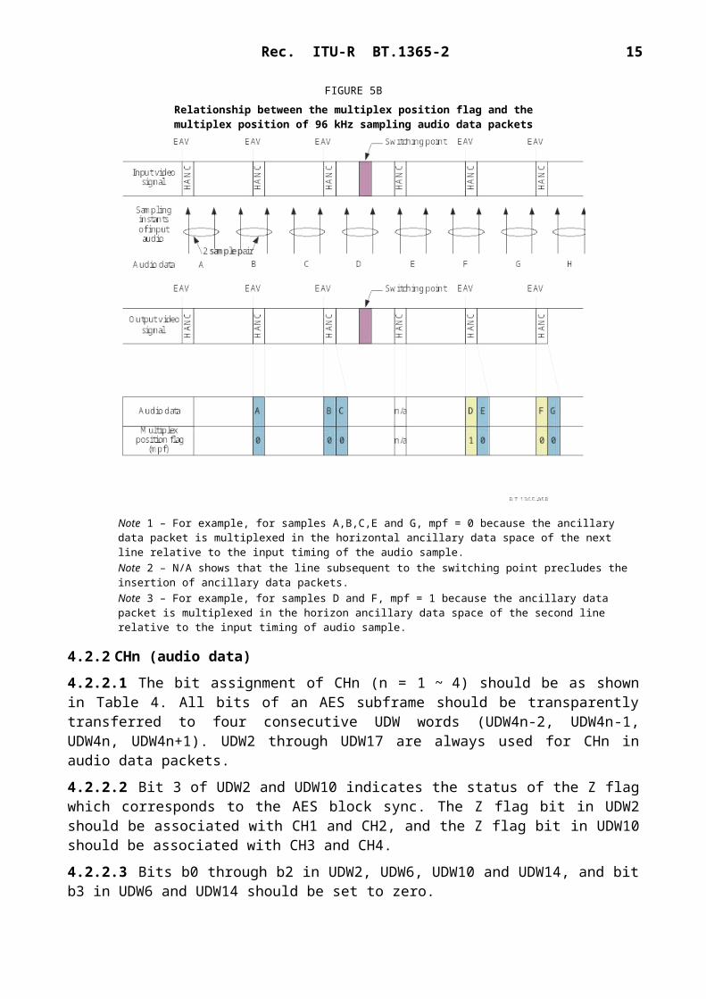
FIGURE 5BRelationship between the multiplex position flag and themultiplex position of 96 kHz sampling audio data packets
Note 1 – For example, for samples A,B,C,E and G, mpf = 0 because the ancillary data packet is multiplexed in the horizontal ancillary data space of the next line relative to the input timing of the audio sample.Note 2 – N/A shows that the line subsequent to the switching point precludes the insertion of ancillary data packets.Note 3 – For example, for samples D and F, mpf = 1 because the ancillary data packet is multiplexed in the horizon ancillary data space of the second line relative to the input timing of audio sample.
4.2.2 CHn (audio data)
4.2.2.1 The bit assignment of CHn (n = 1 ~ 4) should be as shown in Table 4. All bits of an AES subframe should be transparently transferred to four consecutive UDW words (UDW4n-2, UDW4n-1, UDW4n, UDW4n+1). UDW2 through UDW17 are always used for CHn in audio data packets.
4.2.2.2 Bit 3 of UDW2 and UDW10 indicates the status of the Z flag which corresponds to the AES block sync. The Z flag bit in UDW2 should be associated with CH1 and CH2, and the Z flag bit in UDW10 should be associated with CH3 and CH4.
4.2.2.3 Bits b0 through b2 in UDW2, UDW6, UDW10 and UDW14, and bit b3 in UDW6 and UDW14 should be set to zero.

14 Rec. ITU-R BT.1365-2
TABLE 4
Bit-assignment of audio data (CHn)
CH1
Bit number UDW2 UDW3 UDW4 UDW5b9 (MSB)b8b7b6b5b4b3b2b1b0 (LSB)
Not b8Even parity(1)
aud1 3aud1 2aud1 1aud1 0 (LSB)Z000
Not b8Even parity(1)
aud1 11aud1 10aud1 9aud1 8aud1 7aud1 6aud1 5aud1 4
Not b8Even parity(1)
aud1 19aud1 18aud1 17aud1 16aud1 15aud1 14aud1 13aud1 12
Not b8Even parity(1)
P1C1U1V1aud1 23 (MSB)aud1 22aud1 21aud1 20
CH2
Bit number UDW6 UDW7 UDW8 UDW9b9 (MSB)b8b7b6b5b4b3b2b1b0 (LSB)
Not b8Even parity(1)
aud2 3aud2 2aud2 1aud2 0 (LSB)Z000
Not b8Even parity(1)
aud2 11aud2 10aud2 9aud2 8aud2 7 aud2 6aud2 5aud2 4
Not b8Even parity(1)
aud2 19aud2 18aud2 17aud2 16aud2 15aud2 14aud2 13aud2 12
Not b8Even parity(1)
P2C2U2V2aud2 23 (MSB)aud2 22aud2 21aud2 20
CH3
Bit number UDW10 UDW11 UDW12 UDW13b9 (MSB)b8b7b6b5b4b3b2b1b0 (LSB)
Not b8Even parity(1)
aud3 3aud3 2aud3 1aud3 0 (LSB)Z000
Not b8Even parity(1)
aud3 11aud3 10aud3 9aud3 8aud3 7 aud3 6aud3 5aud3 4
Not b8Even parity(1)
aud3 19aud3 18aud3 17aud3 16aud3 15aud3 14aud3 13aud3 12
Not b8Even parity(1)
P3C3U3V3aud3 23 (MSB)aud3 22aud3 21aud3 20
CH4 Bit number UDW14 UDW15 UDW16 UDW17b9 (MSB)b8b7b6b5b4b3b2b1b0 (LSB)
Not b8Even parity(1)
aud4 3aud4 2aud4 1aud4 0 (LSB)Z000
Not b8Even parity(1)
aud4 11aud4 10aud4 9aud4 8aud4 7aud4 6aud4 5aud4 4
Not b8Even parity(1)
aud4 19aud4 18aud4 17aud4 16aud4 15aud4 14aud4 13aud4 12
Not b8Even parity(1)
P4C4U4V4aud4 23 (MSB)aud4 22aud4 21

Rec. ITU-R BT.1365-2 15
aud4 20Notes to Table 4:NOTE 1 – Even parity for b0 through b7NOTE 2 – Z = AES block syncNOTE 3 – Un = AES user bit of CHnNOTE 4 – Pn = AES parity bits of CHnNOTE 5 – aud (0-23) = 24-bit AES audio data of CHnNOTE 6 – Vn = AES sample validity bit of CHnNOTE 7 – Cn = AES channel status bit of CHnNOTE 8 – Value of Vn, Un, Cn and Pn is equal to that of AES subframe, respectively.
4.2.3 Error correction codes
4. 2.3.1 Error correction codes (ECC) are used to correct or detect errors in 24 words from the first word of ADF through UDW17. The error correction code is BCH (31, 25) code. BCH code is formed for each bit sequence of b0-b7, respectively. ECC consists of 6 words determined by the polynomial generator equation:
ECC(X) (X+1)(X5+X2+1) X6+X5+X3+X2+X+1.
Initial value of all FFn is set to zero. The calculation starts at the first word of ADF and ends at the final word of CH4 (UDW17) for each bit of b0 to b7, respectively. The remaining data in the FFn is ECCn. (n 0-5) (FFn stands for “Flip Flop number”. For example, the data of FF0 is ECC0, the data of FF5 is ECC5.)
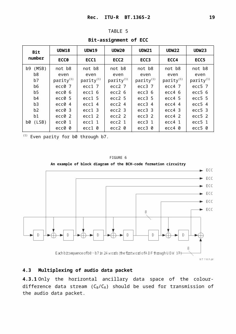
4.2.3.2 Bit-assignment of ECC should be as shown in Table 5. An example of the block diagram of the BCH-code formation circuit is shown in Fig. 6.
TABLE 5
Bit-assignment of ECC
Bit numberUDW18 UDW19 UDW20 UDW21 UDW22 UDW23
ECC0 ECC1 ECC2 ECC3 ECC4 ECC5
b9 (MSB)b8b7b6b5b4b3b2b1
b0 (LSB)
not b8even parity(1)
ecc0 7ecc0 6ecc0 5ecc0 4ecc0 3ecc0 2ecc0 1ecc0 0
not b8even parity(1)
ecc1 7ecc1 6ecc1 5ecc1 4ecc1 3ecc1 2ecc1 1ecc1 0
not b8even parity(1)
ecc2 7ecc2 6ecc2 5ecc2 4ecc2 3ecc2 2ecc2 1ecc2 0
not b8even parity(1)
ecc3 7ecc3 6ecc3 5ecc3 4ecc3 3ecc3 2ecc3 1ecc3 0
not b8even parity(1)
ecc4 7ecc4 6ecc4 5ecc4 4ecc4 3ecc4 2ecc4 1ecc4 0
not b8even parity(1)
ecc5 7ecc5 6ecc5 5ecc5 4ecc5 3ecc5 2ecc5 1ecc5 0
(1) Even parity for b0 through b7.
16 Rec. ITU-R BT.1365-2
FIGURE 6An example of block diagram of the BCH-code formation circuitry
4.3 Multiplexing of audio data packet
4.3.1 Only the horizontal ancillary data space of the colour-difference data stream (CB/CR) should be used for transmission of the audio data packet.
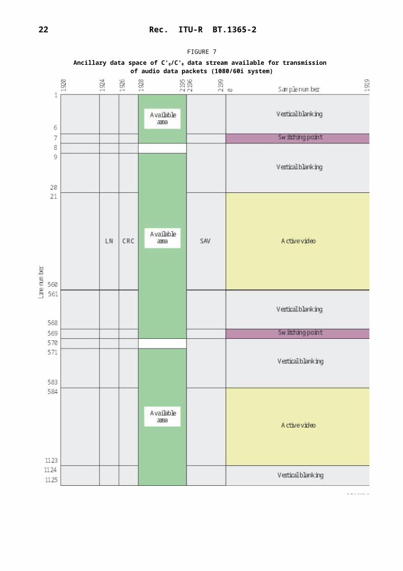
4.3.2 The audio data packet should not be multiplexed into the horizontal ancillary data space of the line subsequent to the switching point defined by the source format. As an example, the ancillary data space available for audio data packet in the 1125/60I system is shown in Fig. 7.
4.3.3 The number of samples per audio channel which can be multiplexed in one horizontal ancillary data space should be less than or equal to Na (Number of audio samples), where Na is defined in the following pseudocode:
No = Int (audio sample rate/line frequency) + 1if No × (the number of total lines per video frame – the number of switching line per video frame)
< (the number of audio samples per video frame)then Na = No + 1else Na = Noif (audio sampling rate == 96 kHz) Na = Even(Na)
The function Even(n) returns the smallest even number that is greater than or equal to n. For example, Even(123) = 124, Even(98) = 98.
When two or more samples of the audio data are transmitted in one horizontal ancillary data block, the packet of the audio sample which appears earlier at the input of the formatter should be transmitted first.
Some video formats may require up to 8 samples per data block (i.e. Na = 8).
4.3.4 An audio data packet should be multiplexed in the horizontal ancillary data space of the first or second line following the line during which the audio sample occurred at the input of the formatter.NOTE 1 – Audio phase must be maintained across the audio groups carrying the multiple-channel audio.

Rec. ITU-R BT.1365-2 17
4.3.5 The audio data packet should be multiplexed following the CRCC words defined in Recommendation ITU-R BT.1120.
4.3.6 When more than two audio data packets are transmitted in one horizontal ancillary data block, the audio data packets should be contiguous with each other.
5 Audio control packet
5.1 Structure of audio control packet
5.1.1 The structure of audio control packet should be as shown in Fig. 8. Audio control packets consist of ancillary data flag (ADF), data identification (DID), data block number (DBN), data count (DC), user data words (UDW) and checksum (CS). ADF, DC and CS are subject to Recommendation ITU-R BT.1364. DC is always 10Bh and DBN is always 200 h.
5.1.2 DID has a value of 1E3h for audio group 1 (channel 1-4), 2E2h for audio group 2 (channel 5-8), 2E1h for audio group 3 (channel 9-12) and 1E0h for audio group 4 (channel 13-16), respectively.
5.1.3 UDW is defined in § 5.2. In this Recommendation, UDWx means the Xth user data word. There are always 11 words in the UDW of an audio control packet, i.e. UDW0, UDW1, …, UDW9, UDW10.

18 Rec. ITU-R BT.1365-2
FIGURE 7Ancillary data space of C'B/C'R data stream available for transmission
of audio data packets (1080/60i system)

Rec. ITU-R BT.1365-2 19
FIGURE 8Structure of audio control packet
5.2 Structure of UDW
UDW consists of five types of data defined in §§ 5.2.1 to 5.2.5. The description in this clause covers only audio group 1. The description for audio groups 2, 3 and 4 is similar to audio group 1 where channels 5, 9 and 13 correspond to channel 1, channels 6, 10 and 14 correspond to channel 2, channels 7, 11 and 15 correspond to channel 3, channels 8, 12 and 16 correspond to channel 4, respectively.
5.2.1 Audio frame number data
5.2.1.1 Audio frame number data (AF) provide a sequential numbering of video frames to indicate where they fall in the progression of non-integer number of samples per video frame (audio frame sequence). The first number of the sequence is always 1 and the final number is equal to the length of the audio frame sequence. A value of AF equal to all zeros indicates that frame numbering is not available. (See Attachment 1.)
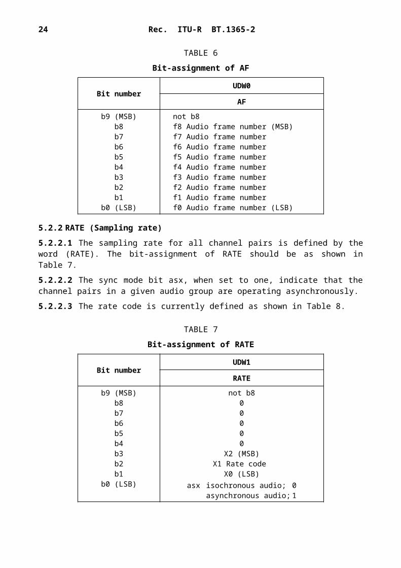
5.2.1.2 The bit-assignment of the AF should be as shown in Table 6. The AF is common for all channels in a given audio group.
5.2.1.3 When channel pairs in a given audio group are operating in asynchronous mode, the AF word in the audio control packet is not used and b0-b8 should be set to zero.
TABLE 6
Bit-assignment of AF
Bit numberUDW0
AF
b9 (MSB)b8b7b6b5b4b3b2b1
b0 (LSB)
not b8f8 Audio frame number (MSB)f7 Audio frame numberf6 Audio frame numberf5 Audio frame numberf4 Audio frame numberf3 Audio frame numberf2 Audio frame numberf1 Audio frame numberf0 Audio frame number (LSB)
20 Rec. ITU-R BT.1365-2
5.2.2 RATE (Sampling rate)
5.2.2.1 The sampling rate for all channel pairs is defined by the word (RATE). The bit-assignment of RATE should be as shown in Table 7.
5.2.2.2 The sync mode bit asx, when set to one, indicate that the channel pairs in a given audio group are operating asynchronously.
5.2.2.3 The rate code is currently defined as shown in Table 8.
TABLE 7
Bit-assignment of RATE
Bit numberUDW1
RATE
b9 (MSB)b8b7b6b5b4b3b2b1
b0 (LSB)
not b800000
X2 (MSB)X1 Rate code
X0 (LSB)asx isochronous audio; 0
asynchronous audio; 1
TABLE 8
Assignment of rate code
X2 X1 X0 Sample rate0 0 0 48.0 kHz0 0 1 44.1 kHz0 1 0 32.0 kHz1 0 0 96.0 kHz0 1 1 Reserved1 0 1 Reserved1 1 0 Reserved1 1 1 Free running
5.2.3 ACT
5.2.3.1 The word ACT indicates active channels. Bits a1 to a4 are set to one for each active channel in a given audio group otherwise they are set to zero. The bit-assignment of ACT is shown in Table 9.
Rec. ITU-R BT.1365-2 21
TABLE 9
Bit-assignment of ACT
Bit numberUDW2
ACT
b9 (MSB)b8b7b6b5b4b3b2b1
b0 (LSB)
not b8even parity(1)
0000a4 active: 1, inactive: 0 (CH4)a3 active: 1, inactive: 0 (CH3)a2 active: 1, inactive: 0 (CH2)a1 active: 1, inactive: 0 (CH1)
(1) Even parity for b0 through b7.
5.2.4 DELm-n
5.2.4.1 The words DELm-n indicate the amount of accumulated audio processing delay relative to video, measured in audio sample intervals, for each channel pair of CHm and CHn.
In the case of 96 kHz sampling, DELm-n should indicate the amount of accumulated audio processing delay relative to video measured in audio sample intervals for the successive two samples of the same AES audio signal carried in CH1, CH2 and CH3, CH4.
5.2.4.2 The bit-assignment of DELm-n should be as shown in Table 10. The e bit is set to one to indicate valid audio delay data. The delay words are referenced to the point where the AES/EBU data are input to the formatter. The delay words represent the average delay value, inherent in the formatting process, over a period no less than the length of the audio frame sequence plus any pre-existing audio delay.
5.2.4.3 The audio delay data (del 0-del 25) is represented in the format of 26-bit 2's complement. Positive values indicate that the video leads the audio.
TABLE 10
Bit-assignment of DELm-n
Bit numberUDW3 UDW4 UDW5 UDW6 UDW7 UDW8
DEL1-2 DEL3-4
b9 (MSB)b8b7b6b5b4b3b2b1
b0 (LSB)
not b8del 7del 6del 5del 4del 3del 2del 1
del 0 (LSB)e
not b8del 16del 15del 14del 13del 12del 11del 10del 9del 8
not b8del 25 ()
del 24 (MSB)del 23del 22del 21del 20del 19del 18del 17
not b8del 7del 6del 5del 4del 3del 2del 1
del 0 (LSB)e
not b8del 16del 15del 14del 13del 12del 11del 10del 9del 8
not b8del 25 ()
del 24 (MSB)del 23del 22del 21del 20del 19del 18del 17

22 Rec. ITU-R BT.1365-2
5.2.5 RSRV
5.2.5.1 The words marked RSRV are reserved for future use.
5.2.5.2 The bit-assignment of RSRV word should be as shown in Table 11.
TABLE 11
Bit-assignment of RSRV
Bit numberUDW9 UDW10
RSRV RSRV
b9 (MSB)b8b7b6b5b4b3b2b1
b0 (LSB)
not b8reserved (set to 0)reserved (set to 0)reserved (set to 0)reserved (set to 0)reserved (set to 0)reserved (set to 0)reserved (set to 0)reserved (set to 0)reserved (set to 0)
not b8reserved (set to 0)reserved (set to 0)reserved (set to 0)reserved (set to 0)reserved (set to 0)reserved (set to 0)reserved (set to 0)reserved (set to 0)reserved (set to 0)
5.3 Multiplexing of the audio control packet
5.3.1 The audio control packets should be transmitted once every field in an interlaced system and once per frame in a progressive system.
5.3.2 The audio control packet should be transmitted in the horizontal ancillary data space of the second line after the switching point of Y parallel data stream.
For example, since the switching point for 1125/60 system exists in Line 7 and 569, the audio control packets are transmitted in the horizontal ancillary data space of Line 9 and Line 571 of the Y data stream. Ancillary data space available for the transmission of audio control packets is shown in Fig. 9.
Rec. ITU-R BT.1365-2 23
FIGURE 9Ancillary data space of Y data stream available for transmission
of audio control packets (1080/60/I system)

24 Rec. ITU-R BT.1365-2
Annex 2 (Normative)Introduction
Annex 1 of this Recommendation defines the 24-bit audio format for up to 16 audio channels at 32, 44.1, or 48 kHz sample rate, or 8 audio channels at 96 kHz sample rate, The intended application is for 1.5 Gbit/s interfaces such as Recommendation ITU-R BT.1120. Annex 2 of this Recommendation, extends the audio format to 32 audio channels at 32, 44.1, or 48 kHz sample rate, or 16 audio channels at 96 kHz sample rate. Specifically, this extension defines the 24-bit audio format for channels 17 up to 32 so that up to 32 audio channels may be multiplexed with source image formats mapped to a 3 Gbit/s serial interface with 148.5 (148.5/1.001) MHz sampling frequency for luminance signal.
For UHDTV interfaces conforming to Recommendation ITU-R BT.2077 Part 3, this Annex applies to each of the 3 Gbit/s data stream pairs making up the overall multiplex.
Annex 2 of this Recommendation defines a Recommendation ITU-R BT.1364 Type 1 packet structure for identifying audio channels numbered from 17 to 32, beyond the 16 channels defined in Annex 1. Four extended audio data packets and four extended audio control packets are identified. One of the extended audio control packets and one of the extended audio data packets are assigned to transport each of the four extended audio groups. Each extended audio group has four channels that carry up to four 24-bit audio channels with 32, 44.1, or 48 kHz sample rates, or up to two 24-bit audio channels with 96 kHz sample rate.
The audio format defined in this Annex 2 is identical to that of Annex 1, except for differences required to define extended audio groups
A1 Extended Audio Data Packet
The structure and multiplexing rules for extended audio data packets are identical to that defined for audio data packets in Annex 1, with the following differences.
A1.1 DID values: The DID values for extended audio data packets should be defined as 1A7h for audio group 5 (channel 17-20), 2A6h for audio group 6 (channel 21-24), 2A5h for audio group 7 (channel 25-28) and 1A4h for audio group 8 (channel 29-32), respectively.
A1.2 Packet/group relationships: Extended audio groups 5 to 8 should be transported only using extended audio data packets defined in this Recommendation. Audio groups 1 to 4 should be transported only using audio data packets defined in Annex 1.
A1.3 Audio data packet and extended audio data packet order: The timing of the nth sample of 32 audio channels on a video line is represented by eight sample instances in eight audio data packets. Since these eight sample instances are independent of each other, the order of these eight packets in the HANC space to which they are multiplexed should be arbitrary.
A2 Extended Audio Control Packet
The structure and multiplexing rules for extended audio control packets are identical to that defined for audio control packets in Annex 1, with the following exceptions.
A2.1 DID values: The DID values for extended audio control packets should be defined as 2A3h for audio group 5 (channel 17-20), 1A2h for audio group 6 (channel 21-24), 1A1h for audio group 7 (channel 25-28) and 2A0h for audio group 8 (channel 29-32), respectively.
Rec. ITU-R BT.1365-2 25
A2.2 Packet/group relationships: Extended audio groups 5 to 8 should be represented only using extended audio control packets defined in this Recommendation. Audio groups 1 to 4 should be transported only using audio data packets defined in Annex 1.
A2.3 Audio control packet and extended audio control packet order: The order of control and extended control packets in the HANC space to which they are multiplexed should be arbitrary.
Attachment 1 (Informative)
Alignment of audio samples for each audio frame
For alignment of AF and sample distribution, the following number of audio samples for each audio frame may be a preferred example.
All audio frame sequences are based on two integer numbers of samples per frame (m and m + 1) with audio frame numbers starting at 1 and proceeding to the end of the sequence. Odd-numbered audio frames (1, 3, 5, etc.) have the larger integer number of samples and even-numbered audio frames (2, 4, 6, etc.) have the smaller integer number of samples with the exception tabulated in Table 1-1. Receivers should have the ability to receive correctly audio data sequence even when this sequence restriction is not implemented.
TABLE 1-1
Example of alignment of audio samples for each audio frame
Television system
Sampling rate (kHz)
Frame sequence
Basic numbering Exceptions
Samples per odd audio frame (m)
Samples per even audio
frame (m + 1)
Frame number
Number of samples
30 frame/s 96.0 1 3 200 None48.0 1 1 600 none44.1 1 1 470 none32.0 3 1 067 1 066 none
29.97 frame/s
96.0 5 3 204 3 202(1) None48.0 5 1 602 1 601 none44.1 100 1 472 1 471 23, 47, 71 1 47132.0 15 1 068 1 067 4, 8, 12 1 068
25 frame/s 96.0 1 3 840 none48.0 1 1 920 none44.1 1 1 764 none32.0 1 1 280 none
(1) Successive samples are carried in audio data packets.
______________


