35
Recommendation ITU-R BT.1685 (09/2004) Structure of inter-station control data conveyed by ancillary data packets BT Series Broadcasting service (television)
| Date post: | 29-Mar-2018 |
| Category: |
Documents |
| Upload: | vuongkhanh |
| View: | 219 times |
| Download: | 6 times |
Recommendation ITU-R BT.1685(09/2004)
Structure of inter-station control data conveyed by ancillary data packets
BT SeriesBroadcasting service
(television)

ii Rec. ITU-R BT.1685
Foreword
The role of the Radiocommunication Sector is to ensure the rational, equitable, efficient and economical use of the radio-frequency spectrum by all radiocommunication services, including satellite services, and carry out studies without limit of frequency range on the basis of which Recommendations are adopted.
The regulatory and policy functions of the Radiocommunication Sector are performed by World and Regional Radiocommunication Conferences and Radiocommunication Assemblies supported by Study Groups.
Policy on Intellectual Property Right (IPR)
ITU-R policy on IPR is described in the Common Patent Policy for ITU-T/ITU-R/ISO/IEC referenced in Annex 1 of Resolution ITU-R 1. Forms to be used for the submission of patent statements and licensing declarations by patent holders are available from http://www.itu.int/ITU-R/go/patents/en where the Guidelines for Implementation of the Common Patent Policy for ITU-T/ITU-R/ISO/IEC and the ITU-R patent information database can also be found.
Series of ITU-R Recommendations (Also available online at http://www.itu.int/publ/R-REC/en)
Series Title
BO Satellite deliveryBR Recording for production, archival and play-out; film for televisionBS Broadcasting service (sound)BT Broadcasting service (television)F Fixed serviceM Mobile, radiodetermination, amateur and related satellite servicesP Radiowave propagationRA Radio astronomyRS Remote sensing systemsS Fixed-satellite serviceSA Space applications and meteorologySF Frequency sharing and coordination between fixed-satellite and fixed service systemsSM Spectrum managementSNG Satellite news gatheringTF Time signals and frequency standards emissionsV Vocabulary and related subjects
Note: This ITU-R Recommendation was approved in English under the procedure detailed in Resolution ITU-R 1.
Electronic PublicationGeneva, 2010
ITU 2010
All rights reserved. No part of this publication may be reproduced, by any means whatsoever, without written permission of ITU.

Rec. ITU-R BT.1685 1
RECOMMENDATION ITU-R BT.1685
Structure of inter-station control dataconveyed by ancillary data packets
(Question ITU-R 130/6)
(2004)
Scope
This Recommendation is applicable to devices which convey inter-station control data for digital broadcasting using ancillary data packets conforming to Recommendation ITU-R BT.1364.
The ITU Radiocommunication Assembly,
considering
a) that in broadcast station networks, various controls between broadcast stations have been performed using control signals multiplexed in the vertical blanking interval of analogue television signals;
b) that many countries are installing digital television production, distribution and broadcasting facilities;
c) that inter-station control data is also required for the distribution of digital television signals;
d) that Recommendation ITU-R BT.1364 specifies the format of ancillary data signals carried in digital component studio interfaces conforming to Recommendations ITU-R BT.656 and ITU-R BT.1120;
e) that some countries are already using the inter-station control data multiplexed as ancillary data signals,
recommends
1 that, for the transmission of inter-station control data as ancillary data signals conforming to Recommendation ITU-R BT.1364, the specification in Annex 1 should be used.
2 that compliance with this Recommendation is voluntary. However, the Recommendation may contain certain mandatory provisions (to ensure e.g. interoperability or applicability) and compliance with the Recommendation is achieved when all of these mandatory provisions are met. The words “shall” or some other obligatory language such as “must” and the negative equivalents are used to express requirements. The use of such words shall in no way be construed to imply partial or total compliance with this Recommendation.
Radiocommunication Study Group 6 made editorial amendments to this Recommendation in November 2009 in accordance with Resolution ITU-R 1.

2 Rec. ITU-R BT.1685
Annex 1
1 General items
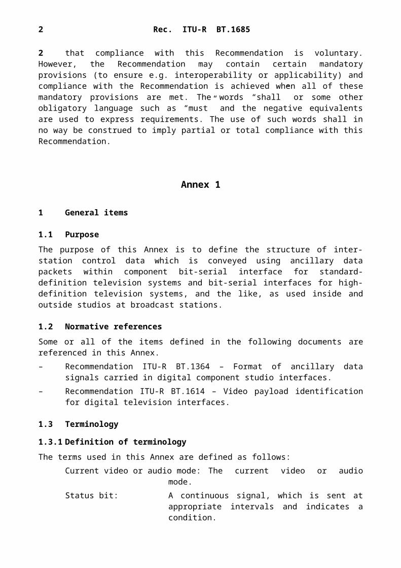
1.1 Purpose
The purpose of this Annex is to define the structure of inter-station control data which is conveyed using ancillary data packets within component bit-serial interface for standard-definition television systems and bit-serial interfaces for high-definition television systems, and the like, as used inside and outside studios at broadcast stations.
1.2 Normative references
Some or all of the items defined in the following documents are referenced in this Annex.– Recommendation ITU-R BT.1364 – Format of ancillary data signals carried in digital
component studio interfaces.– Recommendation ITU-R BT.1614 – Video payload identification for digital television
interfaces.
1.3 Terminology
1.3.1 Definition of terminology
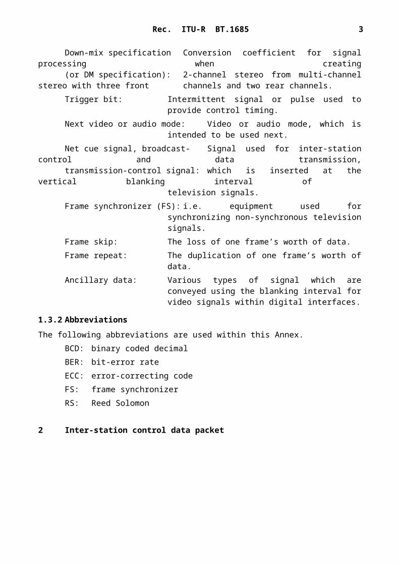
The terms used in this Annex are defined as follows:Current video or audio mode: The current video or audio mode.Status bit: A continuous signal, which is sent at appropriate intervals
and indicates a condition.Down-mix specification Conversion coefficient for signal processing when creating(or DM specification): 2-channel stereo from multi-channel stereo with three front
channels and two rear channels.Trigger bit: Intermittent signal or pulse used to provide control timing.Next video or audio mode: Video or audio mode, which is intended to be used next.Net cue signal, broadcast- Signal used for inter-station control and data transmission,transmission-control signal: which is inserted at the vertical blanking interval of
television signals.Frame synchronizer (FS): i.e. equipment used for synchronizing non-synchronous
television signals.Frame skip: The loss of one frame’s worth of data.Frame repeat: The duplication of one frame’s worth of data.Ancillary data: Various types of signal which are conveyed using the
blanking interval for video signals within digital interfaces.
1.3.2 Abbreviations
The following abbreviations are used within this Annex.BCD: binary coded decimalBER: bit-error rateECC: error-correcting code

Rec. ITU-R BT.1685 3
FS: frame synchronizerRS: Reed Solomon
2 Inter-station control data packet
2.1 Inter-station control data packet format
Inter-station control data is conveyed using inter-station control data packets. The format of the inter-station control data packets shall conform to type 2 ancillary data packets as defined in Recommendation ITU-R BT.1364 and, in this format, one word consists of 10 bits. The format of inter-station control data packets is illustrated in Fig. 1.
2.2 User data word (UDW) format
Inter-station control data uses the UDW of the inter-station control data packet. The UDW comprises an inter-station control data word, an added inter-station control data header word and an error correction parity word (optional). The format of the UDW of an inter-station control data packet is illustrated in Fig. 2.
2.2.1 Inter-station control data header word
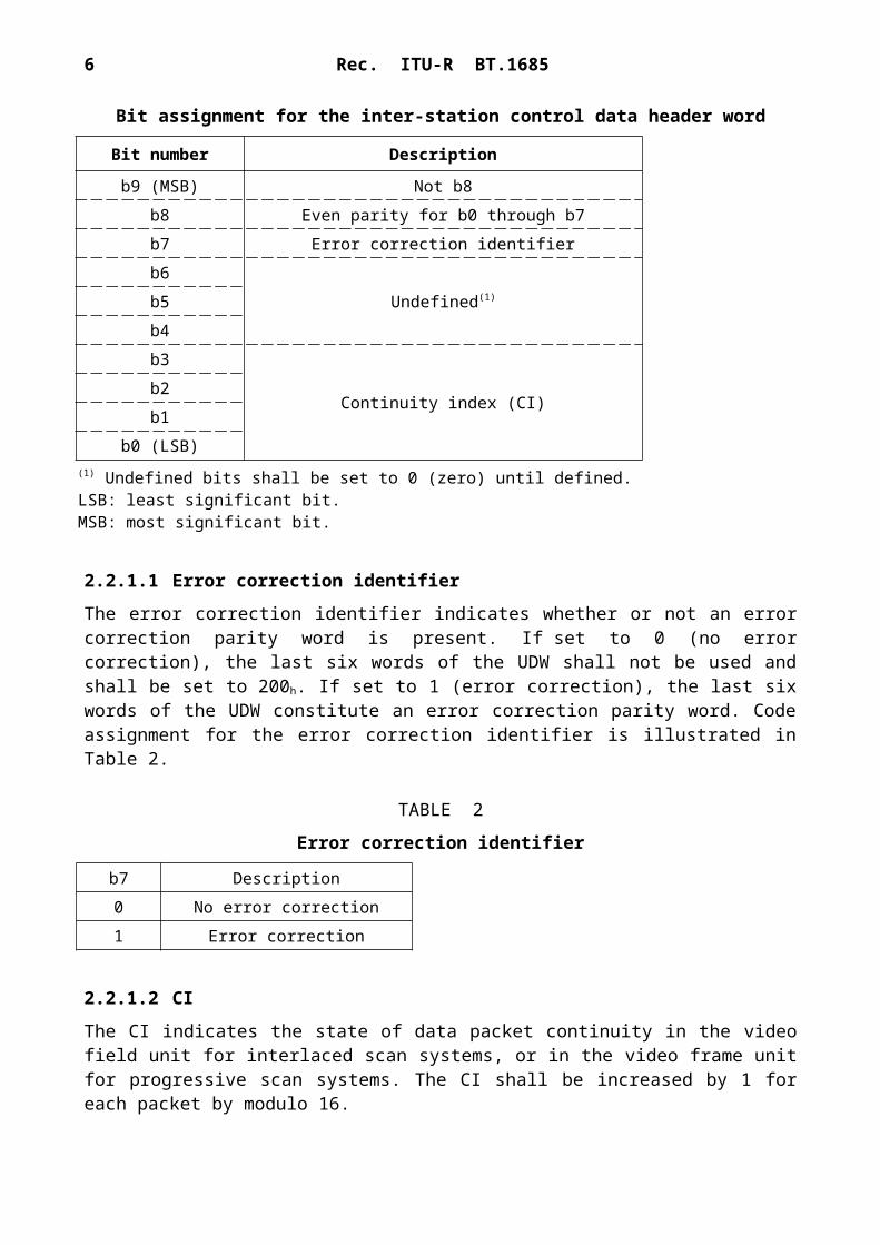
An inter-station control data header of a single word is placed at the front of the UDW. Bit assignment for the inter-station control data header word is illustrated in Table 1.
4 Rec. ITU-R BT.1685
TABLE 1
Rec. ITU-R BT.1685 5
Bit assignment for the inter-station control data header word
Bit number Description
b9 (MSB) Not b8b8 Even parity for b0 through b7b7 Error correction identifierb6
Undefined(1)b5b4b3
Continuity index (CI)b2b1
b0 (LSB)(1) Undefined bits shall be set to 0 (zero) until defined.LSB: least significant bit.MSB: most significant bit.
2.2.1.1 Error correction identifier
The error correction identifier indicates whether or not an error correction parity word is present. If set to 0 (no error correction), the last six words of the UDW shall not be used and shall be set to 200h. If set to 1 (error correction), the last six words of the UDW constitute an error correction parity word. Code assignment for the error correction identifier is illustrated in Table 2.
TABLE 2
Error correction identifier
b7 Description0 No error correction1 Error correction
2.2.1.2 CI
The CI indicates the state of data packet continuity in the video field unit for interlaced scan systems, or in the video frame unit for progressive scan systems. The CI shall be increased by 1 for each packet by modulo 16.
2.2.2 Inter-station control data word
The lower 8 bits (b0 through b7) of the inter-station control data word constitute the inter-station control data. Bit assignment for the inter-station control data word is illustrated in Table 3.
TABLE 3

6 Rec. ITU-R BT.1685
Bit assignment for the inter-stationcontrol data word
Bit number Description
b9 (MSB) Not b8b8 Even parity for b0 through b7b7
Inter-station control data
b6b5b4b3b2b1
b0 (LSB)
2.2.2.1 Inter-station control data format
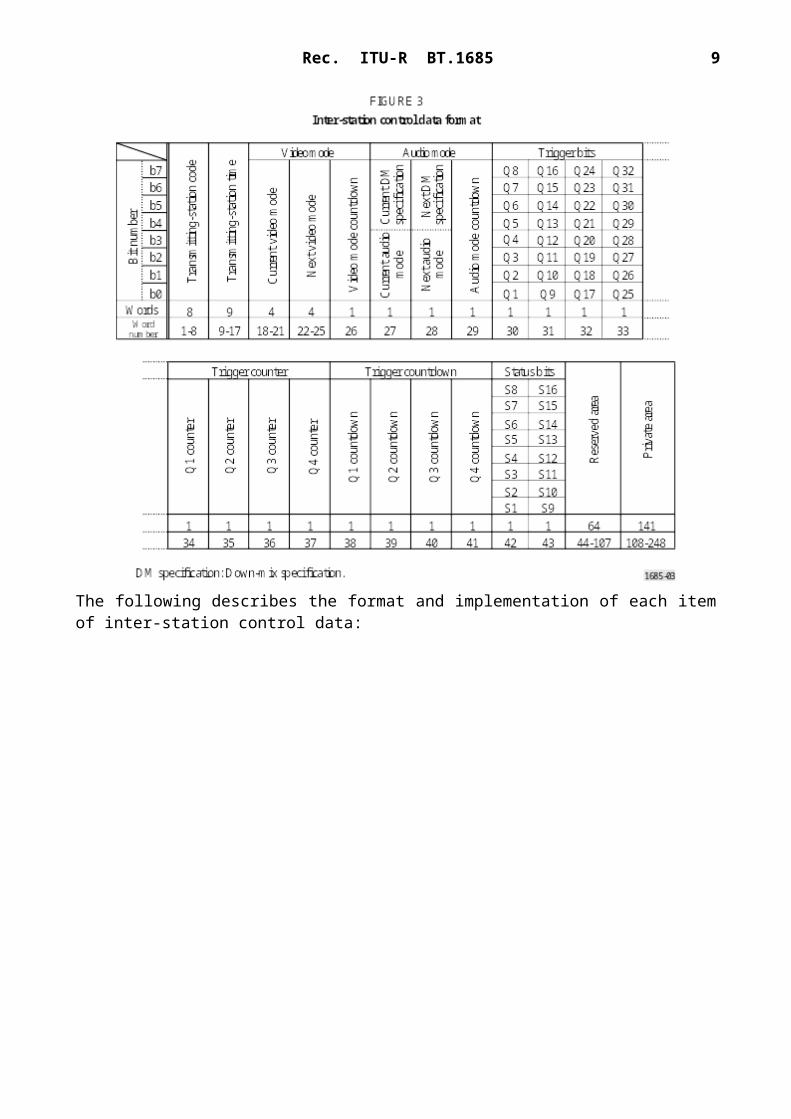
The format of inter-station control data is illustrated in Fig. 3.
The following describes the format and implementation of each item of inter-station control data:

Rec. ITU-R BT.1685 7
a) Transmitting-station code (8 words)
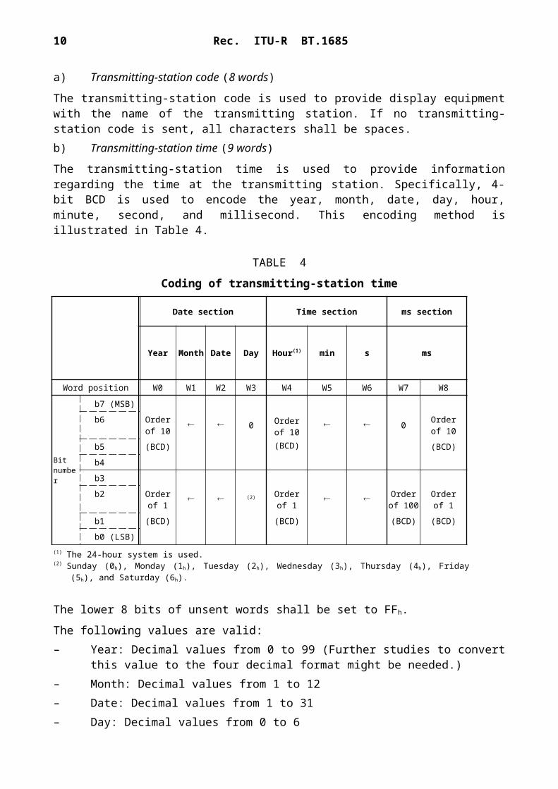
The transmitting-station code is used to provide display equipment with the name of the transmitting station. If no transmitting-station code is sent, all characters shall be spaces.b) Transmitting-station time (9 words)
The transmitting-station time is used to provide information regarding the time at the transmitting station. Specifically, 4-bit BCD is used to encode the year, month, date, day, hour, minute, second, and millisecond. This encoding method is illustrated in Table 4.
TABLE 4
Coding of transmitting-station time
Date section Time section ms section
Year Month Date Day Hour(1) min s ms
Word position W0 W1 W2 W3 W4 W5 W6 W7 W8
Bit number
b7 (MSB)
Order of 10
(BCD)
b6 Order of 10
0 0 Orderof 10
b5 (BCD) (BCD)
b4
b3
b2 Orderof 1
(2) Orderof 1
Orderof 100
Orderof 1
b1 (BCD) (BCD) (BCD) (BCD)
b0 (LSB)(1) The 24-hour system is used.(2) Sunday (0h), Monday (1h), Tuesday (2h), Wednesday (3h), Thursday (4h), Friday (5h), and Saturday (6h).
The lower 8 bits of unsent words shall be set to FFh.
The following values are valid:– Year: Decimal values from 0 to 99 (Further studies to convert this value to the four decimal
format might be needed.)– Month: Decimal values from 1 to 12– Date: Decimal values from 1 to 31– Day: Decimal values from 0 to 6– Hour: Decimal values from 0 to 23– Minute and second: Decimal values from 0 to 59– Millisecond: Decimal values from 0 to 999.c) Current video mode, next video mode (4 words)
8 Rec. ITU-R BT.1685
Current video mode and next video mode are used to indicate video attributes. Specifically, current video mode corresponds to the current attribute; next video mode to the next scheduled attribute. Both current video mode and next video mode are encoded as illustrated in Table 5. By setting the lower 8 bits from the first word (W0) to 00h, it can be indicated that all four words from the corresponding current video mode or next video mode are unused.
TABLE 5
Encoding of video mode
Word position W0 W1 W2 W3
Bit number
b7Version identification:Normally 1
Scan format for transmission:Interlace (0) or progressive (1)NOTE 1: Valid when W0 = 85h
Video aspect ratio:4:3 (0) or 16:9 (1) Reserved area
b6
Video format and digital interface (Table 6)
Scan format for picture:Interlace (0) or progressive (1)
No. of horizontal Y samples:720 (0) Reserved (1)NOTE 1: Valid when W0 = 81h
Channel allocation:No. 1 link (0) or No. 2 link (1)NOTE 1: Valid when W0 = 82h
b5Reserved area
Display range aspect ratio:4:3 (0) or 16:9 (1)
Reserved areab4 Reserved area
b3
Frame rate (Table 7) Sampling structure (Table 8)
b2
b1
b0 Bit depth:8 bits (0) or 10 bits (1)
NOTE 1 – The items valid only for specific W0-values are treated as reserved areas when other W0-values are specified.
TABLE 6
Encoding of video format and digital interface
Code value Video format Digital interface
01h720 × 483 × 50/I, 720 × 576 × 60I
270 Mbit/s (Ref. Rec. ITU-R BT.656)
02h Reserved
03h720 × 483 × 50/I, 720 × 576 × 60I
540 Mbit/s (Ref. Rec. ITU-R BT.799)
04h 1 280 × 720 × 60/P
05h1 920 × 1 080 × 60/I1 920 × 1 080 × 50/I
1.485 Gbit/s (nominal) (Ref. Rec. ITU-R BT.1120)
06h to 7Fh Reserved
Rec. ITU-R BT.1685 9
TABLE 7
Encoding of frame rate
Code value Frame rate(Hz)
0h Undefined1h Reserved2h 24/1.0013h 244h Reserved5h 256h 30/1.0017h 308h Reserved9h 50Ah 60/1.001Bh 60
Ch to Fh Reserved
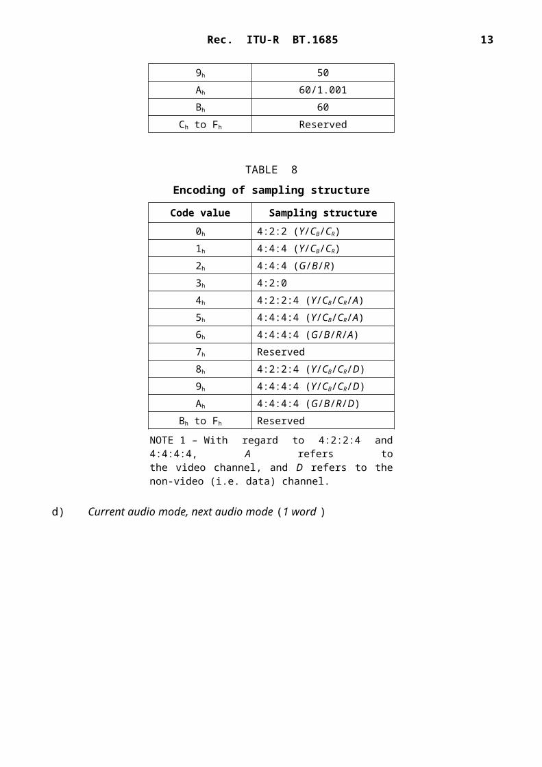
TABLE 8
Encoding of sampling structure
Code value Sampling structure0h 4:2:2 (Y/CB/CR)1h 4:4:4 (Y/CB/CR)2h 4:4:4 (G/B/R)3h 4:2:04h 4:2:2:4 (Y/CB/CR/A)5h 4:4:4:4 (Y/CB/CR/A)6h 4:4:4:4 (G/B/R/A)7h Reserved8h 4:2:2:4 (Y/CB/CR/D)9h 4:4:4:4 (Y/CB/CR/D)Ah 4:4:4:4 (G/B/R/D)
Bh to Fh Reserved
NOTE 1 – With regard to 4:2:2:4 and 4:4:4:4, A refers tothe video channel, and D refers to the non-video (i.e. data) channel.
d) Current audio mode, next audio mode (1 word )

10 Rec. ITU-R BT.1685
Current audio mode and next audio mode indicate the attributes of the audio conveyed together with the video signal. Specifically, current audio mode corresponds to the current attribute; next audio mode to the next scheduled attribute. The lower 5 bits (b0 through b4) of current audio mode and next audio mode provide audio mode data; the upper 3 bits (b5 through b7) provide information regarding the down-mix specification. Encoding of each word is illustrated in Table 9a and Table 9b. However, a down-mix specification is valid only when the audio mode contains a 3/2 or 5.1 format, and in all other cases, this shall be encoded as 000.
TABLE 9a
Encoding of audio mode (b0 to b4)
Code value Audio mode
00h Unused01h M02h 2M(D)03h 3M(D + M)04h 4M(2D)05h 5M(2D + M)06h 6M(3D)07h 7M(3D + M)08h 8M(4D)09h S0Ah 2S0Bh 3S0Ch 4S0Dh 3/00Eh 2/10Fh 3/110h 2/211h 3/212h 3/2/Low frequency effects (LFE) (5.1)13h S + M14h S + D15h 5.1 + S16h 3/1 + S17h 3/2 + S18h 9M or more (M only)19h 5S or more (S only)1Ah Other
1Bh to 1Fh Reserved
Rec. ITU-R BT.1685 11
M: monoS: stereo D: dual mono (2-channel audio).Number of channels for front/rear speakers.Example: 3/2 = 3 front, 2 rear.
TABLE 9b
Encoding of down-mix specification (b5 to b7)
Code valueMatrix-mixdown coefficient
b7 b6 b5
0 0 0 Unspecified0 0 1
Reserved0 1 00 1 1
1 0 0 A=1/√21 0 1 A=1/2
1 1 0 A=1/(2√2)1 1 1 A=0
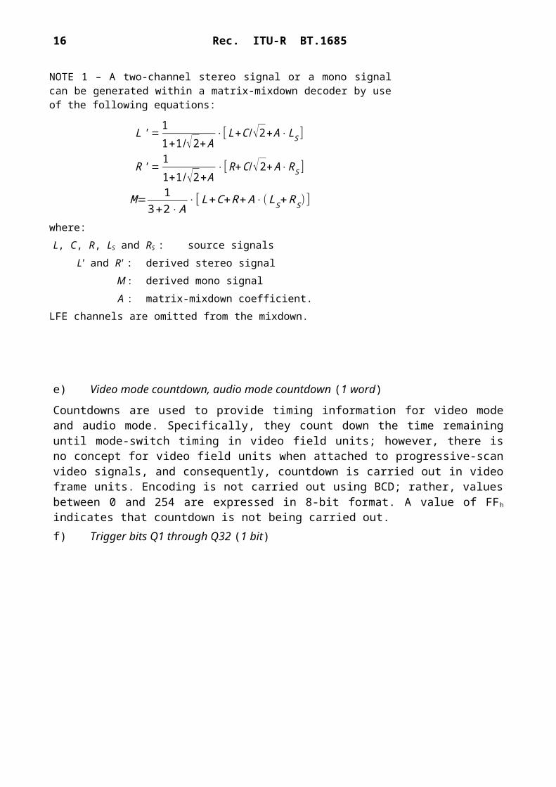
NOTE 1 – A two-channel stereo signal or a mono signal can be generated within a matrix-mixdown decoder by use of the following equations:
L ' = 11+1/√2+ A
⋅[ L+C /√2+ A⋅LS ]
R ' = 11+1/√2+ A
⋅[ R+C /√2+ A⋅RS ]
M= 13+2⋅ A
⋅[ L+C+R+ A⋅(LS+RS) ]
where:L, C, R, LS and RS : source signals
L' and R' : derived stereo signalM : derived mono signalA : matrix-mixdown coefficient.
LFE channels are omitted from the mixdown.
e) Video mode countdown, audio mode countdown (1 word)
Countdowns are used to provide timing information for video mode and audio mode. Specifically, they count down the time remaining until mode-switch timing in video field units; however, there is no concept for video field units when attached to progressive-scan video signals, and consequently, countdown is carried out in video frame units. Encoding is not carried out using BCD; rather, values
12 Rec. ITU-R BT.1685
between 0 and 254 are expressed in 8-bit format. A value of FFh indicates that countdown is not being carried out.f) Trigger bits Q1 through Q32 (1 bit)

Rec. ITU-R BT.1685 13
Trigger bits are used to provide notification of a specific event either in advance or at the required timing. Trigger send is considered to commence when the trigger bit switches from 0 to 1, and the meaning of the bit, send timing, and send duration are arbitrary.g) Trigger counter (1 word )
Trigger counters are used with trigger bit Q1 through Q4. Encoding is not carried out using BCD; rather, values between 0 and 254 are expressed in 8-bit format. A value of FFh indicates that the trigger counter is not being used.h) Trigger countdown (1 word )
Trigger countdowns are used to provide timing information for trigger bits Q1 through Q4. Specifically, they count down the time remaining until the timing specified for the trigger bit in field units; however, there is no concept for field units when attached to progressive-scan video signals, and consequently, countdown is carried out in frame units. Encoding is not carried out using BCD; rather, values between 0 and 254 are expressed in 8-bit format. A value of FFh indicates that countdown is not being carried out.i) Status bits S1 through S16 (1 bit)
Status bits are used to indicate status using the 0 or 1 condition of the bits. Unused bits shall be set to 0, and the meaning of the bits is arbitrary.
j) Reserved area
The reserved area has been included to allow for future expansion of this standard; accordingly, it shall not be used until the corresponding standard has been concluded.
k) Private area
The private area may be freely utilized by the user.
2.2.3 Error correction parity word (optional)
In consideration of the error characteristics of the transmission system, the code RS(254,248) is adopted for the error correction parity word. The length of the protected data word is 248, which is from the second UDW (not including the inter-station control data header word) to the error correction parity word. The RS code is defined as shown below.
The RS code generator polynomial shall be:
G( x )=( x+1)( x+α )( x+α2 )( x+α3 )( x+α4 )( x+α 5 )where is defined by the Galois field GF(28) generator polynomial:
GF ( x )=x8+x4+x3+x2+1If the data word sequence D(x) for the lower 8 bits of the UDW to be protected is expressed as:

14 Rec. ITU-R BT.1685
D( x )=D247 x247+D246 x246+¿⋅¿+D2 x2+D1 x+D0
then the polynomial for error-correction parity words P5, P4, P3, P2, P1, and P0 can be expressed as the remainder P(x) when x6D(x) is divided by G(x).
P( x )=P5 x5+P4 x 4+P3 x3+P2 x2+P1 x+P0
The polynomial representation C(x) of the lower 8 bits of the entire conveyed code is as follows:
C ( x )=x6 D( x )+P( x )Note that for each P(x) word from the conveyed packet, b8 (even parity for b0 through b7) and b9 (inverse of b8) will – in the same way as for D(x) – be added at the two upper MSBs to enable conveyance of a single 10-bit word. Bit allocation for the error correction parity word is illustrated in Table 10; the format of UDW featuring ECC in Fig. 4.
TABLE 10
Bit allocation for error correction parity word
Bit number Description
b9 (MSB) Not b8b8 Even parity for b0 through b7b7
Error correction parity word
b6b5b4b3b2b1
b0 (LSB)
Appendix 1to Annex 1
Supplemental information regarding the operationof inter-station control data
Rec. ITU-R BT.1685 15
1 Inter-station control data header word
1.1 CI
The CI is used to check for the occurrence of frame skipping, frame repeating, freezing, and the like.
1.2 Frame skip and frame repeat
In situations where an FS is used, it is theoretically possible for a single frame’s worth of data to be lost (i.e. frame skip) or to be duplicated (i.e. frame repeat). As for status signals and trigger signals, if an operation, which sends two or more frames continuously, is applied, no problems will be experienced as a result of the occurrence of either frame skip or frame repeat. However, in the case of countdown signals, a countdown value may result in a discontinuity.
2 Inter-station control data word
This Recommendation does not define whether the various items of inter-station control data word are mandatory or optional. The requirement for usage of these items shall be determined separately in operational guidelines.
2.1 Transmitting-station code
In principle, the transmitting-station codes are broadcast constantly using the current abbreviated name of the corresponding station. Although a unique code should be assigned to each individual transmitting station, codes should be assigned so that transmitting stations are identified using only character No. 1 through character No. 4, because character No. 5 and all subsequent characters are optional.
When no transmitting-station code is to be broadcast or when only broadcasting as far as character No. 4, the space character is to be used for all non-broadcast characters; however the use of spaces within valid character strings is not prohibited. Accordingly, care must be taken in the design of functionality for the display of transmitting-station codes so that spaces are not decoded as the end of character strings. In situations where difficulty exists in replacement of the transmitting-station code when re-transmitting to other stations after recording, or when re-transmitting via another station, re-transmission using the transmitting-station code of the original transmitting station is permitted.
2.2 Transmitting-station time
It is assumed that the transmitting-station time could be used for the adjustment of device timing or as an index similar to a time code for broadcasting recorded materials. The yearly calendar shall be used independent of date changing within broadcasting control systems.
It is also assumed that the date section (i.e. year, month, date, and day) and the time section (hour, minute, and second) are sent, but the millisecond section is not sent.

16 Rec. ITU-R BT.1685
2.3 Video mode
The format adopted for video mode corresponds to addition of a definition for display-range aspect ratio to the video payload identification as defined in Recommendation ITU-R BT.1614. The video aspect ratio and the display-range aspect ratio are specified as follows:– For letterbox mode: Video aspect ratio 4:3, Display-range aspect ratio 16:9– For squeeze mode: Video aspect ratio 16:9, Display aspect ratio 16:9– For side panel mode: Video aspect ratio 16:9, Display aspect ratio 4:3
This text is not applicable to the following video formats and digital interfaces defined in Recommendation ITU-R BT.1614:– 4:4:4:4i, 270 Mbit/s dual link (in certain 02h cases)– 525i/p, 1.485 Gbit/s (nominal) (06h)– 1125i/p, 1.485 Gbit/s dual link (nominal) (07h).
Note that the hexadecimal values shown in parentheses correspond to the “Video format & Digital interface” values as indicated by bit 6 through B0 of word 0.
2.4 Audio mode
This Recommendation does not define the method for mapping of audio channels to the broadcast channel, and the method for utilization of the down-mix specification, as it has relation to the process for encoding or broadcasting of audio, or function of receivers. In situations where this standard is applied in the control of audio encoding parameters, it will be necessary to determine the correspondence of audio mode values and control parameter values between the stations.
The down-mix specification is a conversion coefficient for signal processing used when creating 2-channel stereo from multi-channel stereo with three front channels and two rear channels. It is provided to allow the audio-creation wishes of the sender to be clearly indicated. In consideration of the fact that this specification – including current and next information – will need to be handled in the same way as the audio mode, it was realized using the upper order 3 bits of the audio-mode data, thus ensuring compatibility with earlier standards.
Note that restrictions apply to the audio modes for which the specification of conversion coefficients is valid, and for this reason, care must be taken in situations where no specification is made. As a result of the addition of the down-mix specification, the audio-mode reserved area now extends from 1Bh to 1Fh, and this has been determined to present no current or future difficulties.
2.5 Video mode countdown and audio mode countdown
A countdown value can be used for video mode and audio mode. The maximum possible value of a countdown is 254 (video fields); therefore, when field frequency of the video signal is 60 fields/s, countdown will be possible from approximately 4.2 s in advance. A jump of a countdown value, an inversion, and a repetition may occur as a result of a skip, a repeat, etc. of a video frame. Suitable processing is desired for it.

Time (fields)
Rec. ITU-R BT.1685 17
The example of use of a video or audio mode, and countdown is shown in Table 11. This is an example in the following conditions.– Countdown is started 3 s before changing the mode.– The countdown value reaches 0 at the field just prior to changing the mode.– Sending of the next mode is carried out even when countdown is not being performed.
TABLE 11
Example of countdown for audio and video modes
Timing Countdown value Current mode Next mode
255(FFh) A B255(FFh) A B
3 s in advance 179 A B178 A B
2 fields in advance 1 A B1 field in advance 0 A BSwitch timing 255(FFh) B C
255(FFh) B C
2.6 Trigger bits
32 bits can be used as a trigger signal. Actual number of the bits to be used, the meaning of bits, the send timing, the send duration, and the like are to be determined in operational guidelines. Each bit of a trigger bit is independent; however, multiple bits may be sent simultaneously to provide indication of phenomena requiring multi-bit representation.
2.7 Trigger counters
Trigger counters may be used with trigger signals Q1 through Q4, and these are provided to allow visual confirmation of trigger signals. Typical uses of these counters are presented below.– For each programme, trigger counters indicate the sequence position for the next trigger. A
counter is reset to 1 at the beginning of the programme, and simultaneously with trigger sending out. During said reset at the beginning of the programme, resetting of a value of 0 is permitted in cases where it is not intended to send triggers during the programme. Furthermore, when the final trigger is sent out in a programme, you may reset to 0.
– The next of 254 is set to 0, when not resetting per programme and applying as a cyclic counter.
2.8 Trigger countdown
Time (fields)
18 Rec. ITU-R BT.1685
Trigger countdowns may be used with trigger signals Q1 through Q4. The maximum possible value of a countdown is 254 (fields); therefore, when the field frequency of the video signal is 60 fields/s, countdown will be possible from approximately 4.2 s in advance.
In the case of Q1 through Q4, it is conceivable that a countdown will not be sent even though the corresponding trigger signal is sent; however, trigger signals do not feature flags to indicate whether or not a countdown will be sent. Countdown operational guidelines, including the solution for cases where there is an inconsistency in the timing indicated by the trigger signal and that indicated by the countdown, need to be determined in the actual operation. Also, there is a possibility that skipping, repeating, and other similar video-frame problems will result in countdown values being skipped, reversed, or repeated, and it is desirable that the appropriate processing is prepared for those cases.
Table 12 presents a typical use of a countdown for trigger signals, and the following conditions are assumed in this case:– Video switching is indicated by a trigger featuring a countdown.– Trigger sending is carried out over the 0.5 s period starting 3 s in advance of the required
timing.– Countdown is started at the field where trigger sending commences.– The countdown value reaches 0 at the field immediately prior to the required timing.
TABLE 12
Example of countdown for trigger signals
Timing Countdown value Trigger bit value Video
255(FFh) 0 A255(FFh) 0 A
3 s in advance 179 1 A178 1 A
150 1 A2.5 s in advance 149 0 A
2 fields in advance 1 0 A1 field in advance 0 0 ARequired timing 255(FFh) 0 B
255(FFh) 0 B
2.9 Status bits

Rec. ITU-R BT.1685 19
Although 16 bits may be used for status bits, actual number of the bits to be used and the meaning of bits are to be determined in operational guidelines. Each bit from a status bit is independent; however, multiple bits may be sent simultaneously to indicate a status signal defined by multi-bit representation.
3 Error in inter-station control data packets
3.1 Types of error
It is considered that errors could occur in the following cases during internal station transmission, and during inter-station transmission:– station-internal baseband transmission (coaxial cable);– station-internal baseband transmission (optical fibre);– inter-station baseband transmission (optical fibre) (see Note to Table 13);– inter-station compressed transmission (optical fibre);– FS frame skipping and frame repeating.
These can be broadly classified into errors in the transmission system and frame skipping or repeating by the FS. The error characteristics of each type are illustrated in Table 13.
TABLE 13
Error types and characteristics*
Error type Error characteristics BER
Transmission system error (optical fibre)
Burst and random errors Very low: 10–10 or less
Transmission system error (coaxial cable)
Burst and random errors Assumed to be approximately 10–10
FS frame skipping or frame repeating
Loss of one frame of dataDuplication of one frame of data
Once every three months
* Synchronous digital hierarchy (SDH) transmission using optical fibres is assumed. See ITU-T Recommendation G.957 (1995) – Optical interfaces for equipment and systems relating to the synchronous digital hierarchy.
3.2 Correction of errors in inter-station control data packets
In accordance with the fact that the structure of ancillary data makes block-specific correction of errors ideal for inter-station control data packets, block encoding was selected in place of convolution coding. Furthermore, since difficulties would exist in the use of different encoding methods for transmission-line burst errors and random errors, burst error was considered to be the more prevalent and the decision was taken to implement RS code.
Although Turbo code is available as an extension of RS code, evaluation of the adoption of this method was suspended due to its requirement for large-scale calculation processing and the lack of effectiveness in the correction of transmission-line errors.

20 Rec. ITU-R BT.1685
With a BER of 1010, quality in the transmission lines is high, and particularly in the case of baseband transmission, it was determined that the number of error words per packet was low; accordingly, RS code with 3-word correction and 6-word error detection was adopted for usage. Note that this differs from the 8-word correction and 16-word error detection for RS(255,239) 1 as used in transmission for digital satellite broadcasting and digital terrestrial television broadcasting.
There is an error correction identifier defined in the header word of UDW. Although RS(255,249), which includes header word as protection data via RS code, was considered the outcome of studies resulted in the header word being no longer subjected to this data protection and therefore, RS(254,248) was adopted.
1 Using abbreviated Reed Solomon code, RS(204,188).


