Recommendation ITU-R M.2058-0 (02/2014) Characteristics of a digital system, named navigational data for broadcasting maritime safety and security related information from shore-to-ship in the maritime HF frequency band M Series Mobile, radiodetermination, amateur and related satellite services
Transcript
Recommendation ITU-R M.2058-0(02/2014)
Characteristics of a digital system, named navigational data for
broadcasting maritime safety and security related information
from shore-to-ship in the maritime HF frequency band
M SeriesMobile, radiodetermination, amateur
and related satellite services
ii Rec. ITU-R M.2058-0
Foreword
The role of the Radiocommunication Sector is to ensure the rational, equitable, efficient and economical use of the radio-frequency spectrum by all radiocommunication services, including satellite services, and carry out studies without limit of frequency range on the basis of which Recommendations are adopted.
The regulatory and policy functions of the Radiocommunication Sector are performed by World and Regional Radiocommunication Conferences and Radiocommunication Assemblies supported by Study Groups.
Policy on Intellectual Property Right (IPR)
ITU-R policy on IPR is described in the Common Patent Policy for ITU-T/ITU-R/ISO/IEC referenced in Annex 1 of Resolution ITU-R 1. Forms to be used for the submission of patent statements and licensing declarations by patent holders are available from http://www.itu.int/ITU-R/go/patents/en where the Guidelines for Implementation of the Common Patent Policy for ITU-T/ITU-R/ISO/IEC and the ITU-R patent information database can also be found.
Series of ITU-R Recommendations(Also available online at http://www.itu.int/publ/R-REC/en)
Series Title
BO Satellite deliveryBR Recording for production, archival and play-out; film for televisionBS Broadcasting service (sound)BT Broadcasting service (television)F Fixed serviceM Mobile, radiodetermination, amateur and related satellite servicesP Radiowave propagationRA Radio astronomyRS Remote sensing systemsS Fixed-satellite serviceSA Space applications and meteorologySF Frequency sharing and coordination between fixed-satellite and fixed service systemsSM Spectrum managementSNG Satellite news gatheringTF Time signals and frequency standards emissionsV Vocabulary and related subjects
Note: This ITU-R Recommendation was approved in English under the procedure detailed in Resolution ITU-R 1.
Electronic PublicationGeneva, 2014
ITU 2014
All rights reserved. No part of this publication may be reproduced, by any means whatsoever, without written permission of ITU.
Characteristics of a digital system, named navigational data forbroadcasting maritime safety and security related information
from shore-to-ship in the maritime HF frequency band(2014)
Scope
This Recommendation describes an HF radio system, named Navigational Data HF (NAVDAT HF), for use in the maritime mobile service, operating in the frequency bands of Appendix 17 for digital broadcasting of maritime safety and security related information from shore-to-ship. The operational characteristics and system architecture of this radio system are included in Annexes 1 and 2. The two different modes of broadcasting data are detailed in Annexes 3 and 4. The NAVDAT HF is complementary to the NAVDAT 500 kHz, described in Recommendation ITU-R M.2010 in terms of radio coverage.
Keywords
HF, Maritime, NAVDAT, broadcast, digital
Abbreviations/Glossary
BER Bit error rate
DRM Digital radio mondiale
DS Data stream
GMDSS Global maritime distress and safety system
GNSS Global navigation satellite system
HF High Frequency
IMO International Maritime Organization
ITU International Telecommunication Union
LF Low frequency
MER Modulation error rate
MF Medium frequency
MIS Modulation information stream
NAVDAT Navigational Data (the system name)
NAVTEX Navigational Telex (the system name)
NBDP Narrow band direct printing
NM Nautical mile (1 852 metres)
NVIS Near vertical incidence sky wave
OFDM Orthogonal frequency division multiplexing
QAM Quadrature amplitude modulation
PEP Peak envelope power
RMS Root mean square
2 Rec. ITU-R M.2058-0
SFN Single frequency network
SIM System of information and management
S/N Signal-to-noise ratio
TIS Transmitter information stream
WRC World Radiocommunication Conference
The ITU Radiocommunication Assembly,
considering
a) that high speed data broadcast from shore-to-ships enhances operational efficiency and maritime safety;
b) that the existing Maritime Safety Information (MSI) system operating in narrow band direct printing (NBDP) HF has limited capacity;
c) that emerging maritime navigation systems increase the demand for data transmission from shore-to-ship;
d) that the MF band provides a limited geographical coverage,
recognizing
that the Digital Radio Mondiale (DRM) system referenced in Annex 4 has been incorporated in Recommendation ITU-R BS.1514-2,
noting
that Recommendation ITU-R M.2010 describes the NAVDAT system operating at 500 kHz,
recommends
1 that the operational characteristics for the broadcasting of maritime safety and security related information in the HF frequency bands should be in accordance with Annex 1;
2 that the system architecture of the broadcasting system for maritime safety and security related information in the HF frequency bands should be in accordance with Annex 2;
3 that the technical characteristics and modem protocols for digital data transmission of maritime safety and security related information from shore-to-ships in the HF frequency band should be in accordance with Annex 3 or Annex 4;
4 that the frequencies listed in Annex 5, which belongs to Appendix 17 should be utilized for operating the NAVDAT HF system.
Rec. ITU-R M.2058-0 3
Annex 1
Operational characteristics
The NAVDAT HF system can use a simple time-slot allocation similar to the NAVTEX system which could be coordinated by IMO.
That NAVDAT HF system can also work on single frequency network (SFN) as described in Annex 4. In this case, the transmitters are frequency synchronized and the transmit data must be the same for all transmitters.
The NAVDAT HF digital system offers a free broadcast transmission of any kind of message from shore-to-ships with possibility of encryption.
1 Type of messages
Any broadcasting message should be provided by a secure and controlled source.
Message types broadcast can include, but are not limited to, the following:– safety of navigation;– security;– piracy;– search and rescue;– meteorological messages;– piloting or harbour messages;– vessel traffic service files transfer.
2 Broadcast modes
2.1 General broadcast
These messages are broadcasted for the attention of all ships.
2.2 Selective broadcast
These messages are broadcasted for the attention of a group of ships or in a specific navigation area.
2.3 Dedicated message
These messages are addressed to one ship, using the maritime mobile service identity.
4 Rec. ITU-R M.2058-0
Annex 2
System architecture
1 The broadcast transmission path
The NAVDAT system is organized by performing the following functions:– System of information and management (SIM):
– collects and controls all kinds of information;– creates message files to be transmitted;– creates transmitting program according to message files priority and need of repetition.
– Shore network:– assures the transportation of the message files from sources to the transmitters.
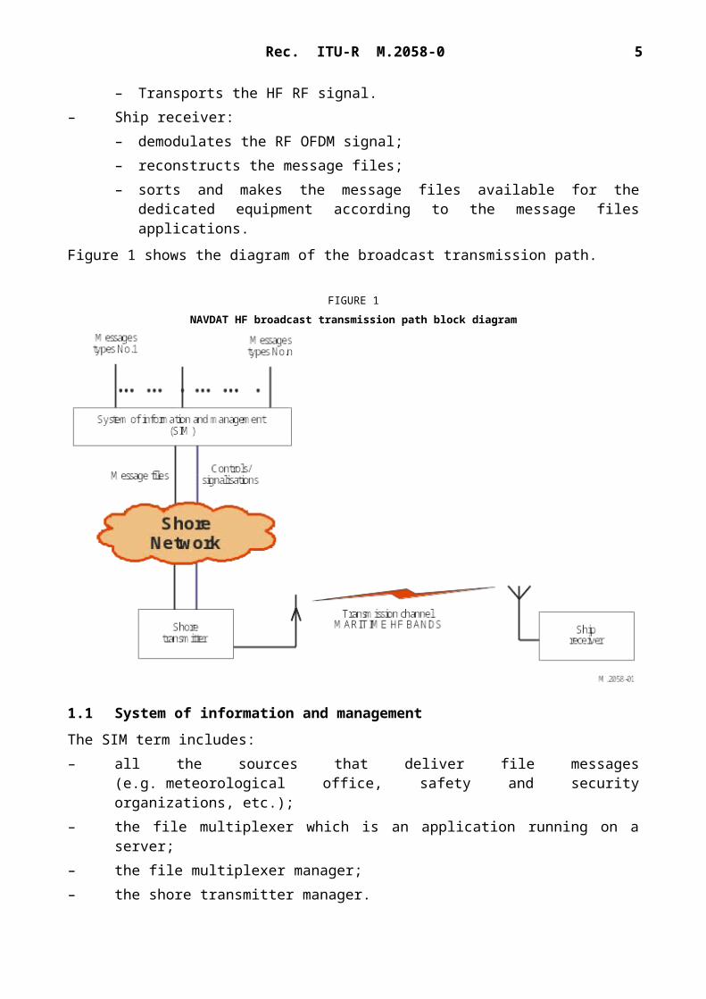
– Shore transmitter:– receives the message files from SIM;– translates message files to orthogonal frequency division multiplexing (OFDM) signal;– transmits RF signal to the antenna for broadcast to ships.
– Transmission channel:– Transports the HF RF signal.
– Ship receiver:– demodulates the RF OFDM signal;– reconstructs the message files;– sorts and makes the message files available for the dedicated equipment according to
the message files applications.
Figure 1 shows the diagram of the broadcast transmission path.
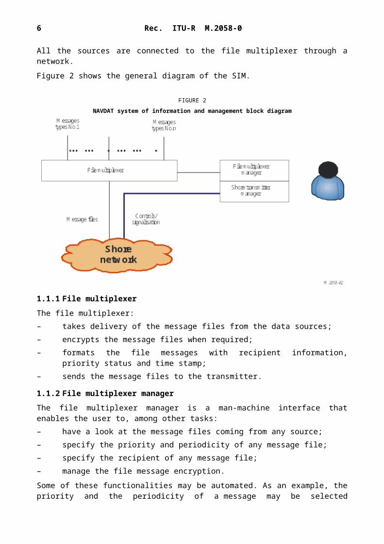
The SIM term includes:– all the sources that deliver file messages (e.g. meteorological office, safety and security
organizations, etc.);– the file multiplexer which is an application running on a server;– the file multiplexer manager;– the shore transmitter manager.
All the sources are connected to the file multiplexer through a network.
Figure 2 shows the general diagram of the SIM.
6 Rec. ITU-R M.2058-0
FIGURE 2NAVDAT system of information and management block diagram
1.1.1 File multiplexer
The file multiplexer:– takes delivery of the message files from the data sources;– encrypts the message files when required;– formats the file messages with recipient information, priority status and time stamp;– sends the message files to the transmitter.
1.1.2 File multiplexer manager
The file multiplexer manager is a man-machine interface that enables the user to, among other tasks:– have a look at the message files coming from any source;– specify the priority and periodicity of any message file;– specify the recipient of any message file;– manage the file message encryption.
Some of these functionalities may be automated. As an example, the priority and the periodicity of a message may be selected according to the source it comes from or the source may specify the priority in the message.
1.1.3 Shore transmitter manager
The shore station manager is a man-machine interface connected to the transmitter through the network; it makes it possible to supervise the transmitter status by indications such as: – transmit acknowledgment;– alarms;– effective transmit power;– synchronization report;
Rec. ITU-R M.2058-0 7
and to control the transmitter parameters, such as:– transmit power;– OFDM parameters (pilot subcarriers, error coding, etc.);– transmission schedule.
1.2 Shore network
The shore network can use a broadband link, a low data rate link or a local file sharing.
1.3 Shore transmitter description
A coastal transmitting station consists of this minimum configuration:– one local server connected to a protected access;– one OFDM modulator;– one HF RF amplifier;– one transmit antenna with matching unit;– one GNSS receiver or atomic clock for synchronization;– one monitoring receiver with its antenna.
1.3.1 Shore system architecture
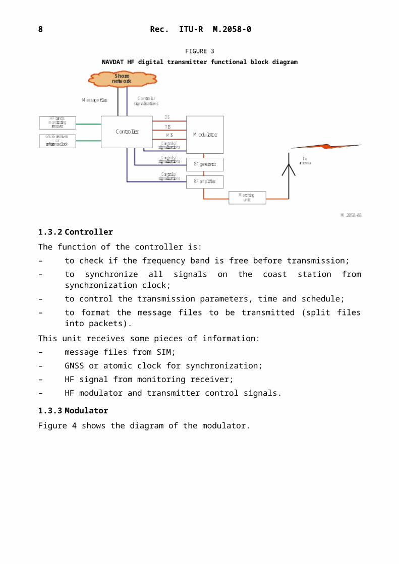
Figure 3 shows the block diagram of an HF digital transmitter.
FIGURE 3NAVDAT HF digital transmitter functional block diagram
1.3.2 Controller
The function of the controller is:– to check if the frequency band is free before transmission;– to synchronize all signals on the coast station from synchronization clock;– to control the transmission parameters, time and schedule;– to format the message files to be transmitted (split files into packets).
8 Rec. ITU-R M.2058-0
This unit receives some pieces of information:– message files from SIM;– GNSS or atomic clock for synchronization;– HF signal from monitoring receiver;– HF modulator and transmitter control signals.
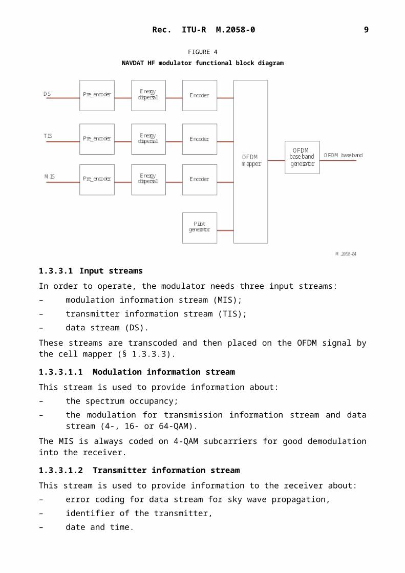
In order to operate, the modulator needs three input streams:– modulation information stream (MIS);– transmitter information stream (TIS);– data stream (DS).
These streams are transcoded and then placed on the OFDM signal by the cell mapper (§ 1.3.3.3).
1.3.3.1.1 Modulation information stream
This stream is used to provide information about:– the spectrum occupancy;– the modulation for transmission information stream and data stream (4-, 16- or 64-QAM).
The MIS is always coded on 4-QAM subcarriers for good demodulation into the receiver.
Rec. ITU-R M.2058-0 9
1.3.3.1.2 Transmitter information stream
This stream is used to provide information to the receiver about:– error coding for data stream for sky wave propagation,– identifier of the transmitter,– date and time.
The TIS can be coded on 4- or 16-QAM.
1.3.3.1.3 Data stream
It contains the message files to transmit (these message files were previously formatted by the file multiplexer).
1.3.3.2 Error correction coding
The error correction scheme determines the robustness of the coding. The code rate is the ratio between useful and raw data rate. It illustrates the transmission efficiency and can vary from 0.5 to 0.75 depending on the error correction schemes and modulation patterns.
1.3.3.3 Orthogonal frequency division multiplexing generation
The three streams (MIS, TIS and DS) are formatted:– encoding;– energy dispersal.
A cell mapper organizes the OFDM cells with the formatted streams and the pilot cells. The pilot cells are transmitted for the receiver to estimate the radio channel and synchronize on the RF signal.
An OFDM signal generator creates the OFDM baseband according to the output of the cell mapper.
1.3.4 HF RF generator
A HF RF generator transposes the baseband signal to the final frequency RF output carrier.
An amplifier brings the RF signal to the desired power.
1.3.5 RF amplifier
The function of this stage is to amplify the HF signal from the generator output to the necessary level to obtain the desired radio coverage.
The OFDM transmission introduces a crest factor on the RF signal. This crest factor must stay in the range 7 to 10 dB at the RF amplifier output for a correct modulation error rate (MER).
The output RF power of shore transmitter can be adjusted up to 10 kW PEP according to the frequencies bands:
The RF amplifier is connected to the transmit antenna through the impedance matching unit.NOTE – Not necessary in case of use of a broadband antenna.
10 Rec. ITU-R M.2058-0
1.3.7 Global navigation satellite system receiver and a backup atomic reference clock
The clock is used to synchronize the local controller.
1.3.8 Monitoring receiver
The monitoring receiver checks that the frequency is free before transmission and offers possibility to check the transmission.
1.4 Transmission channel: radio coverage estimation
HF frequencies are fully dependent on rules of sky wave propagation (by reflection from the ionosphere) which are linked to some parameters such as: day or night, hours, seasons, sunspot cycle, type of transmitting antenna, and radio noise on the received area.
In this situation, it is necessary to use the right frequency all the time. Existing HF propagation software could help to select the right frequency. An NVIS antenna can be used to improve the regional coverage. Multicast by coupling all transmitters on one broadband antenna is also a possibility.
The ship receiver can also scan all allowed frequencies in order to select the best received signal (see Annex 3, § 1.6).
Annex 3
NAVDAT HF technical characteristics
1 Modulation principle
The system uses OFDM which is a modulation technology for digital transmissions.
1.1 Introduction
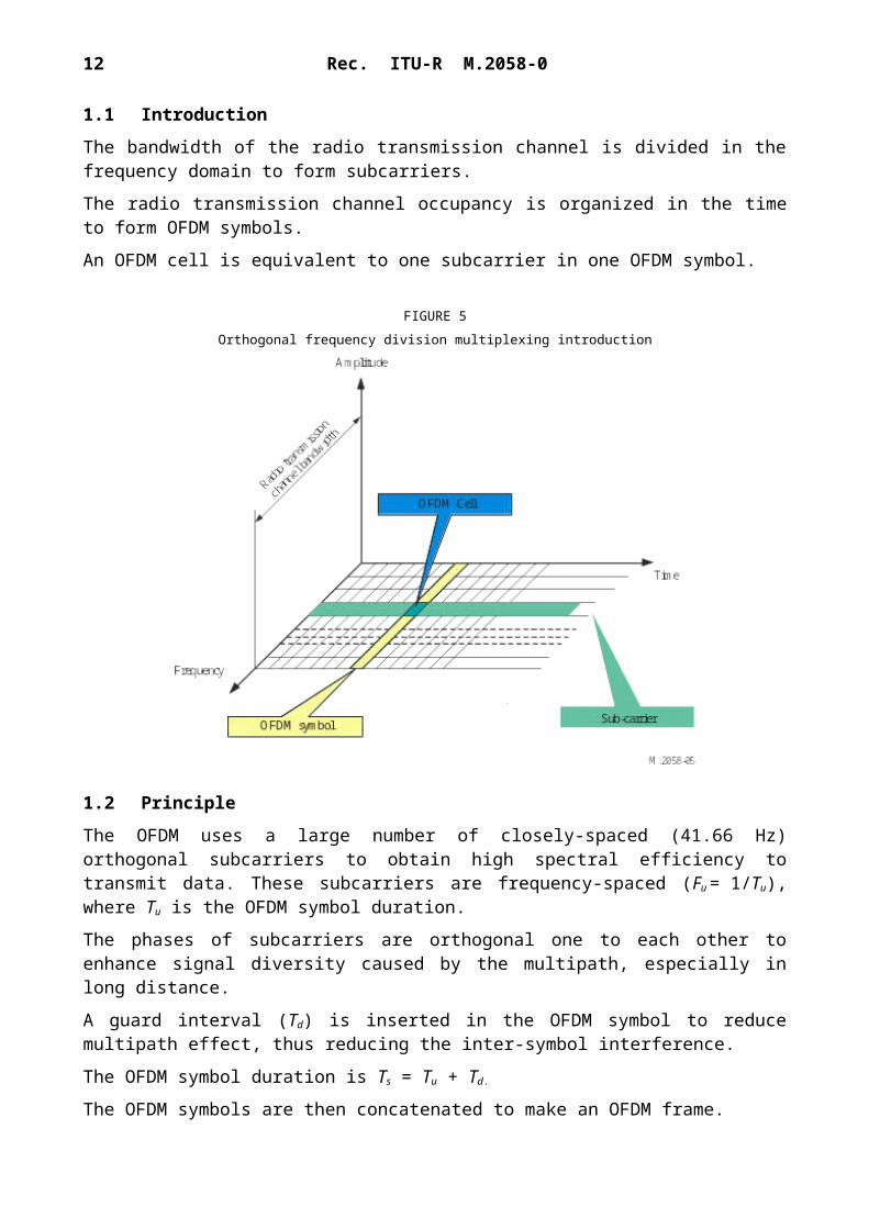
The bandwidth of the radio transmission channel is divided in the frequency domain to form subcarriers.
The radio transmission channel occupancy is organized in the time to form OFDM symbols.
An OFDM cell is equivalent to one subcarrier in one OFDM symbol.
Rec. ITU-R M.2058-0 11
FIGURE 5Orthogonal frequency division multiplexing introduction
1.2 Principle
The OFDM uses a large number of closely-spaced (41.66 Hz) orthogonal subcarriers to obtain high spectral efficiency to transmit data. These subcarriers are frequency-spaced (Fu = 1/Tu), where Tu is the OFDM symbol duration.
The phases of subcarriers are orthogonal one to each other to enhance signal diversity caused by the multipath, especially in long distance.
A guard interval (Td) is inserted in the OFDM symbol to reduce multipath effect, thus reducing the inter-symbol interference.
The OFDM symbol duration is Ts = Tu + Td.
The OFDM symbols are then concatenated to make an OFDM frame.
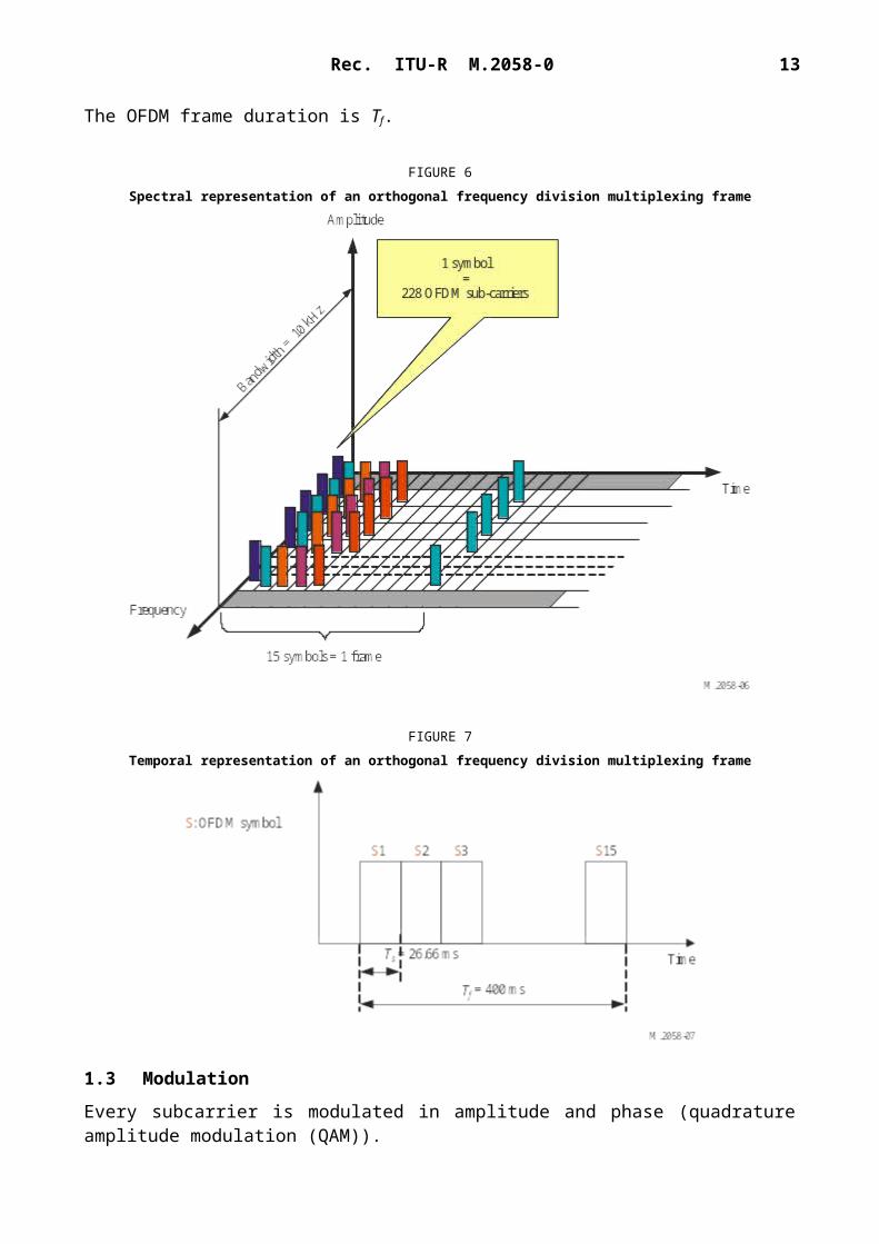
The OFDM frame duration is Tf.
12 Rec. ITU-R M.2058-0
FIGURE 6Spectral representation of an orthogonal frequency division multiplexing frame
FIGURE 7Temporal representation of an orthogonal frequency division multiplexing frame
1.3 Modulation
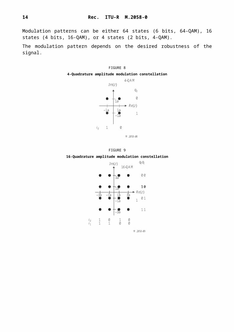
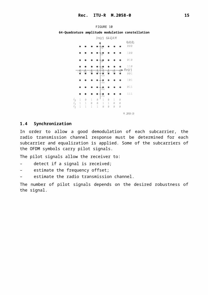
Every subcarrier is modulated in amplitude and phase (quadrature amplitude modulation (QAM)).
Modulation patterns can be either 64 states (6 bits, 64-QAM), 16 states (4 bits, 16-QAM), or 4 states (2 bits, 4-QAM).
The modulation pattern depends on the desired robustness of the signal.
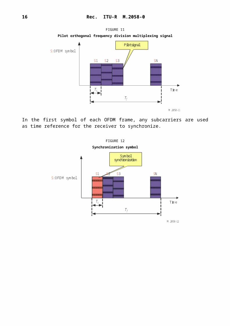
In order to allow a good demodulation of each subcarrier, the radio transmission channel response must be determined for each subcarrier and equalization is applied. Some of the subcarriers of the OFDM symbols carry pilot signals.
The pilot signals allow the receiver to:– detect if a signal is received;– estimate the frequency offset;– estimate the radio transmission channel.
The number of pilot signals depends on the desired robustness of the signal.
FIGURE 11Pilot orthogonal frequency division multiplexing signal
In the first symbol of each OFDM frame, any subcarriers are used as time reference for the receiver to synchronize.
FIGURE 12Synchronization symbol
Rec. ITU-R M.2058-0 15
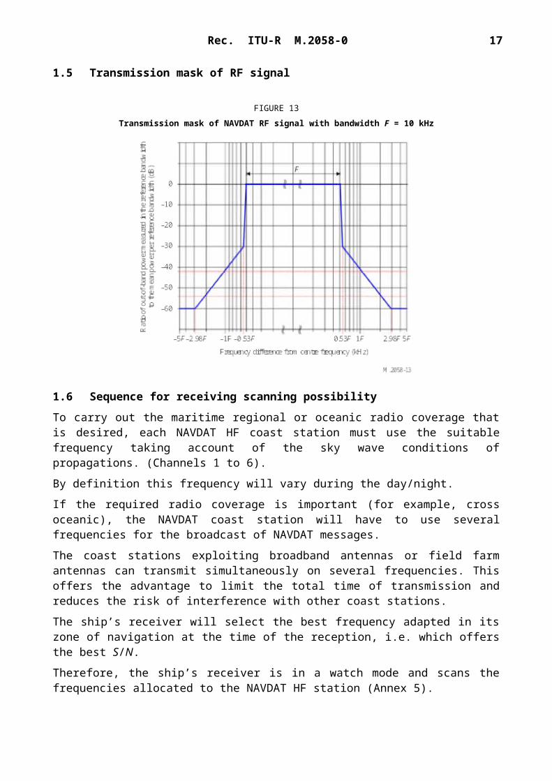
1.5 Transmission mask of RF signal
FIGURE 13Transmission mask of NAVDAT RF signal with bandwidth F = 10 kHz
1.6 Sequence for receiving scanning possibility
To carry out the maritime regional or oceanic radio coverage that is desired, each NAVDAT HF coast station must use the suitable frequency taking account of the sky wave conditions of propagations. (Channels 1 to 6).
By definition this frequency will vary during the day/night.
If the required radio coverage is important (for example, cross oceanic), the NAVDAT coast station will have to use several frequencies for the broadcast of NAVDAT messages.
The coast stations exploiting broadband antennas or field farm antennas can transmit simultaneously on several frequencies. This offers the advantage to limit the total time of transmission and reduces the risk of interference with other coast stations.
The ship’s receiver will select the best frequency adapted in its zone of navigation at the time of the reception, i.e. which offers the best S/N.
Therefore, the ship’s receiver is in a watch mode and scans the frequencies allocated to the NAVDAT HF station (Annex 5).
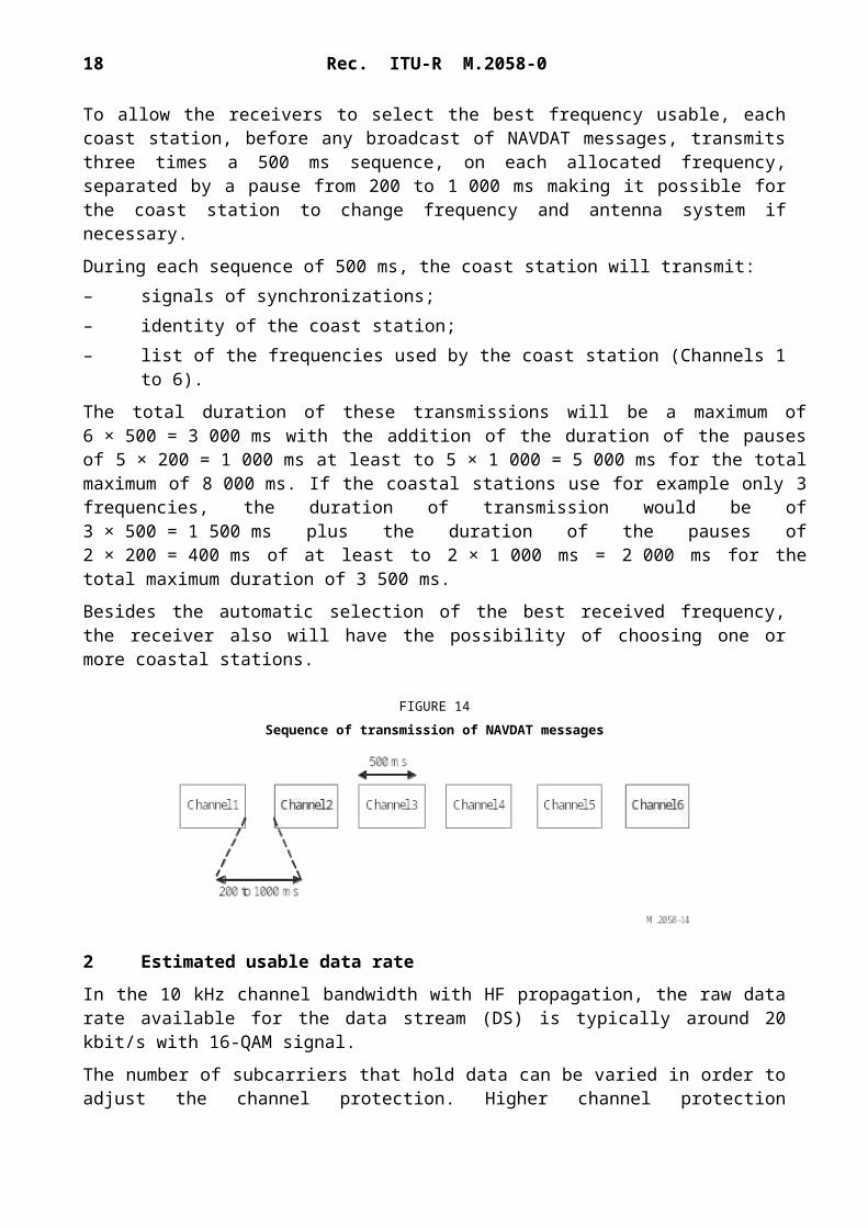
To allow the receivers to select the best frequency usable, each coast station, before any broadcast of NAVDAT messages, transmits three times a 500 ms sequence, on each allocated frequency, separated by a pause from 200 to 1 000 ms making it possible for the coast station to change frequency and antenna system if necessary.
During each sequence of 500 ms, the coast station will transmit:– signals of synchronizations;– identity of the coast station;– list of the frequencies used by the coast station (Channels 1 to 6).
16 Rec. ITU-R M.2058-0
The total duration of these transmissions will be a maximum of 6 × 500 = 3 000 ms with the addition of the duration of the pauses of 5 × 200 = 1 000 ms at least to 5 × 1 000 = 5 000 ms for the total maximum of 8 000 ms. If the coastal stations use for example only 3 frequencies, the duration of transmission would be of 3 × 500 = 1 500 ms plus the duration of the pauses of 2 × 200 = 400 ms of at least to 2 × 1 000 ms = 2 000 ms for the total maximum duration of 3 500 ms.
Besides the automatic selection of the best received frequency, the receiver also will have the possibility of choosing one or more coastal stations.
FIGURE 14Sequence of transmission of NAVDAT messages
2 Estimated usable data rate
In the 10 kHz channel bandwidth with HF propagation, the raw data rate available for the data stream (DS) is typically around 20 kbit/s with 16-QAM signal.
The number of subcarriers that hold data can be varied in order to adjust the channel protection. Higher channel protection (protection against multipath, fading, delay, etc.) results in a lower number of useful subcarriers.
Error correction coding must then be applied to the raw data rate to obtain the useful data rate. With a code rate of 0.5 to 0.75, the useful data rate is then between 10 and 15 kbit/s.
A higher code rate provides a higher useful data rate but the radio coverage is accordingly reduced.
3 NAVDAT ship receiver
3.1 NAVDAT ship receiver description
The ship receiver block diagram is shown in Fig. 15.
A NAVDAT HF receiver can be fully compatible with the NAVDAT MF receiver by only adapting the front end to receive the 500 kHz + the HF frequencies. Scan is allowed on HF channels but 500 kHz and HF reception are completely separate and independent. Antenna can be the same like active whip.
A typical NAVDAT 500 kHz and NAVDAT HF digital receiver is composed of several basic blocks:– reception antenna and GNSS antenna;– RF front end;– demodulator;– file demultiplexer;– controller;
Rec. ITU-R M.2058-0 17
– power supply.
FIGURE 15NAVDAT receiver logical diagram
3.1.1 Reception antenna and global navigation satellite antenna
The receiving antenna can be an H field antenna (recommended on a noisy ship) or an E field antenna.
A GNSS antenna (or connection to the existing ship GNSS receiver) is also needed in order to obtain the ship position.
3.1.2 RF front end
This block includes the RF filter, RF amplifier and baseband output with for all a scanning possibility.
High sensitivity and high dynamic range are necessary.
3.1.3 Demodulator
This stage demodulates the baseband OFDM signal and recreates the data stream that holds the transmitted message files.
The NAVDAT receiver should be able to detect the following modulation parameters automatically:– 4-, 16- or 64-QAM;
18 Rec. ITU-R M.2058-0
– subcarriers scheme;– type of error coding.
In addition to the DS, it reports the information filled in the TIS and MIS. Furthermore, it reports complementary information about the channel such as:– estimated S/N;– BER;– MER.
3.1.4 File demultiplexer
The file demultiplexer:– receives the message files from the controller;– verifies that the message files are marked for its attention (type of broadcast mode);– decrypts the message files if needed/able;– makes the message files available for the terminal application that will use the message
files;– deletes the out-of-date message files.
Depending on the final application, the message file can be:– stored on an onboard server accessible through the ship network;– sent directly to the final application.
A man-machine interface should be available in order to display the dedicated messages and to configure the interface with the application dedicated onboard devices (e.g. e-navigation) and manage the ship board permissions (ship identification, encryption). This interface may be a dedicated application running on an external computer while the receiver may be a black-box device.
3.1.5 Controller
The controller:– extracts the message files from the DS (merge packets into files);– interprets the TIS and MIS and the other pieces of information given by the demodulator;– collects the following information from the file demultiplexer:
• total number of decoded message files;• number of available message files;• error event (e.g. decrypt errors).
A man-machine interface may be available in order to display and check the reception parameters.
3.1.6 Power supply
The main power supply must be adapted to the main power supply of the ship.
4 NAVDAT ship receiver performance specifications
These assumed ship receiver specifications are set out below with the objective to obtain minimum S/N for a good OFDM demodulation (4-QAM, 16-QAM or 64-QAM).
Frequency band 4 to 22 MHz maritime bandAdjacent channel protection > 40 dB @ 5 kHzNoise factor < 10 dBUsable sensitivity for BER = 10−4 after error correction < −100 dBmDynamic > 80 dBMinimal usable RF field (with adapted receiving antenna) 20 dB(µV/m)
Annex 4
Single frequency network mode of Digital Radio Mondiale
1 Explanation of Digital Radio Mondiale
The international digital radio broadcast standard Digital Radio Mondiale (DRM) is used for digital radio broadcasting at MF and HF. DRM is a proven technology that provides superior coverage, improves signal fidelity (through digital error correction coding), eliminates multi-path interference (including sky-wave interference) and thus extends coverage from sky-wave propagated signals. DRM broadcasts are implemented in both 16-QAM and 64-QAM modulation modes, depending on coverage requirements, transmitter location, power and antenna height.
1.1 Single frequency network operating mode
The DRM system is capable of supporting what is called “single frequency network (SFN) operation”. This is the case where a number of transmitters transmit on the same frequency, and at the same time, identical data signals. Generally, these transmitters are arranged to have overlapping coverage areas, within which a radio will receive signals from more than one transmitter. Provided that these signals arrive within a time difference of less than the guard interval, they will provide positive signal reinforcement. Thus, the service coverage will be improved at that location compared to that obtained if there was only a single transmitter providing service to that location. By careful design, and using a number of transmitters in a SFN, a region or country may be completely covered using a single frequency, and in this application, a single time slot, thus drastically improving spectrum efficiency.
20 Rec. ITU-R M.2058-0
Annex 5
Frequencies for NAVDAT HF system
Channel Maritime frequencyband
Central frequency Limits
C1 4 MHz band 4 226 kHz 4 221 to 4 231 kHzC2 6 MHz band 6 337.5 kHz 6 332.5 to 6 342.5 kHzC3 8 MHz band 8 443 kHz 8 438 to 8 448 kHzC4 12 MHz band 12 663.5 kHz 12 658.5 to 12 668.5 kHzC5 16 MHz band 16 909.5 kHz 16 904.5 to 16 914.5 kHzC6 22 MHz band 22 450.5 kHz 22 445.5 to 22 455.5 kHz