Page 1 Temporary Works Excellence Award 2017 MTRC Contract 1128 SOV TO ADMIRALTY TUNNELS The MTR Shatin to Central Link (SCL) - Contract 1128 South Ventilation Building to Admiralty Tunnels comprises the permanent works and the associated temporary works necessary for Tunnel Boring Machine (TBM) tunnels between South Ventilation Building (SOV) and Admiralty station, short sections of cut and cover tunnels near MTR Tsuen Wan Line South Ventilation Building (SVB) and Fenwick Pier Emergency Egress Point (FPP). . The key challenge of the project is to construct the Eastern Tunnels and Western Tunnels by Tunnel Boring Machine (TBM), as both tunnels go through the city’s busiest districts. Meticulous project planning is essential in aiding the TBMs to navigate through a large volume of pile obstructions and utilities with zero interruption of services to citizens. To cope with the complex geological conditions, two different types of TBMs are being employed for excavation – a slurry TBM and an variable density TBM. . Contract No. : MTR Shatin to Central Link – (Contract 1128) Client : MTR Corporation Main Contractor : Dragages Bouygues Joint Venture (DBJV) Contract Sum : HK$ 5,227 M Total Tunnel length : 2,328 m Project Background FPP Peanut Shaft for TBM Launching Innovative Pre-stressed TBM Launching structure Eastern Tunnel Western Tunnel Exhibition Station Admiralty Station To facilitate the TBM launching, a temporary launching structure is required to safely withstand and transmit the TBM thrust force to the surroundings. Due to the limited space available in this project, an innovative pre-stressed TBM Launching structure was proposed. TBM thrust force will first be transmitted to the starwheel thrust frame, and then to the concrete bell through Pre-stressing high tension steel bars. The force in the concrete bell will further be transferred to the RC collar / tympanum at the front and base slab at the back. The pre- stressing system provides an effective control to the movement induced by the TBM thrust force. A 40m deep shaft at Fenwick Pier is constructed for: 1. Launching TBM (2 times), 2. Construction of permanent Emergency Egress Point (EEP), 3. Construction of permanent Cut & Cover Tunnels (C&C) and connection with C&C tunnel sections to be built in Area 2 further east, afterwards, 4. Supply of Permanent Way of Railway such as 18m long rails and a 20m long Work Train before closing up of the opening in permanent structure. The shaft is constrained by the existing 10m deep MTR South Intake Cell (SIC) basement, the existing operating MTR Tsuen Wan Line (TWL), the existing old seawall, and the immediate adjacent contract WDII project. FPP Peanut Shaft “TBM Launch Shaft” WDII project MTR South Intake Cell (SIC) ~10m deep basement MTR TWL Ventilation Building (SVB) WDII project WDII Middle Ventilation Building ~30m deep basement MTR TWL Ventilation Building (SVB) MTR South Intake Cell (SIC) ~10m deep basement SCL Tu n n e ls SCL Tu n n e ls
Transcript
Page 1
Temporary Works Excellence Award 2017
MTRC Contract 1128 SOV TO ADMIRALTY TUNNELS
The MTR Shatin to Central Link (SCL) - Contract 1128 South
Ventilation Building to Admiralty Tunnels comprises the permanent
works and the associated temporary works necessary for Tunnel
Boring Machine (TBM) tunnels between South Ventilation Building
(SOV) and Admiralty station, short sections of cut and cover tunnels
near MTR Tsuen Wan Line South Ventilation Building (SVB) and
Fenwick Pier Emergency Egress Point (FPP). .
The key challenge of the project is to construct the Eastern Tunnels
and Western Tunnels by Tunnel Boring Machine (TBM), as both
tunnels go through the city’s busiest districts. Meticulous project
planning is essential in aiding the TBMs to navigate through a large
volume of pile obstructions and utilities with zero interruption of
services to citizens. To cope with the complex geological
conditions, two different types of TBMs are being employed for
excavation – a slurry TBM and an variable density TBM. .
Contract No. : MTR Shatin to Central Link –
(Contract 1128)
Client : MTR Corporation
Main Contractor : Dragages Bouygues Joint Venture
(DBJV)
Contract Sum : HK$ 5,227 M
Total Tunnel length : 2,328 m
Project Background FPP Peanut Shaft for TBM Launching
Innovative Pre-stressed TBM Launching structure
Eastern
Tunnel
Western
Tunnel
Exhibition
Station
Admiralty
Station
To facilitate the TBM launching, a temporary launching structure is required to
safely withstand and transmit the TBM thrust force to the surroundings.
Due to the limited space available in this project, an innovative pre-stressed TBM
Launching structure was proposed.
TBM thrust force will first be
transmitted to the starwheel thrust
frame, and then to the concrete bell
through Pre-stressing high tension
steel bars. The force in the concrete
bell will further be transferred to the
RC collar / tympanum at the front
and base slab at the back. The pre-
stressing system provides an
effective control to the movement
induced by the TBM thrust force.
A 40m deep shaft at Fenwick Pier is constructed for:
1. Launching TBM (2 times),
2. Construction of permanent Emergency Egress Point (EEP),
3. Construction of permanent Cut & Cover Tunnels (C&C) and connection with C&C
tunnel sections to be built in Area 2 further east, afterwards,
4. Supply of Permanent Way of Railway such as 18m long rails and a 20m long Work
Train before closing up of the opening in permanent structure.
The shaft is constrained by the existing 10m deep MTR South Intake Cell (SIC)
basement, the existing operating MTR Tsuen Wan Line (TWL), the existing old seawall,
and the immediate adjacent contract WDII project.
FPP Peanut Shaft
“TBM Launch Shaft”
WDII project
MTR South
Intake Cell
(SIC)
~10m deep
basement
MTR TWL
Ventilation
Building (SVB) WDII project
WDII Middle
Ventilation
Building
~30m deep
basement
MTR TWL
Ventilation
Building (SVB)
MTR South
Intake Cell
(SIC)
~10m deep
basement
SCL
Tunnels
SCL
Tunnels
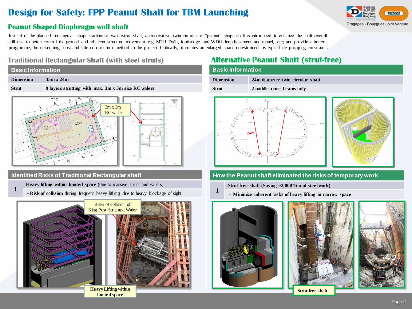
Basic Information
Dimension 35m x 24m
Strut 9 layers strutting with max. 3m x 3m size RC walers
Design for Safety: FPP Peanut Shaft for TBM Launching
Traditional Rectangular Shaft (with steel struts) Alternative Peanut Shaft (strut-free)
Basic Information
Dimension 24m diameter twin circular shaft
Strut 2 middle cross beams only
Heavy Lifting within
limited space Strut-free shaft
24m
3m x 3m
RC waler
Identified Risks of Traditional Rectangular shaft
1 Heavy lifting within limited space (due to massive struts and walers)
- Risk of collision during frequent heavy lifting due to heavy blockage of sight
How the Peanut shaft eliminated the risks of temporary work
1 Strut-free shaft (Saving ~2,000 Ton of steel work)
- Minimize inherent risks of heavy lifting in narrow space
Risks of collision of
King Post, Strut and Waler
Instead of the planned rectangular shape traditional waler/strut shaft, an innovative twin-circular or “peanut” shape shaft is introduced to enhance the shaft overall
stiffness to better control the ground and adjacent structure movement e.g. MTR TWL, footbridge and WDII deep basement and tunnel, etc; and provide a better
programme, housekeeping, cost and safe construction method to the project. Critically, it creates an enlarged space unrestrained by typical de-propping constraints.
Peanut Shaped Diaphragm wall shaft
Page 2
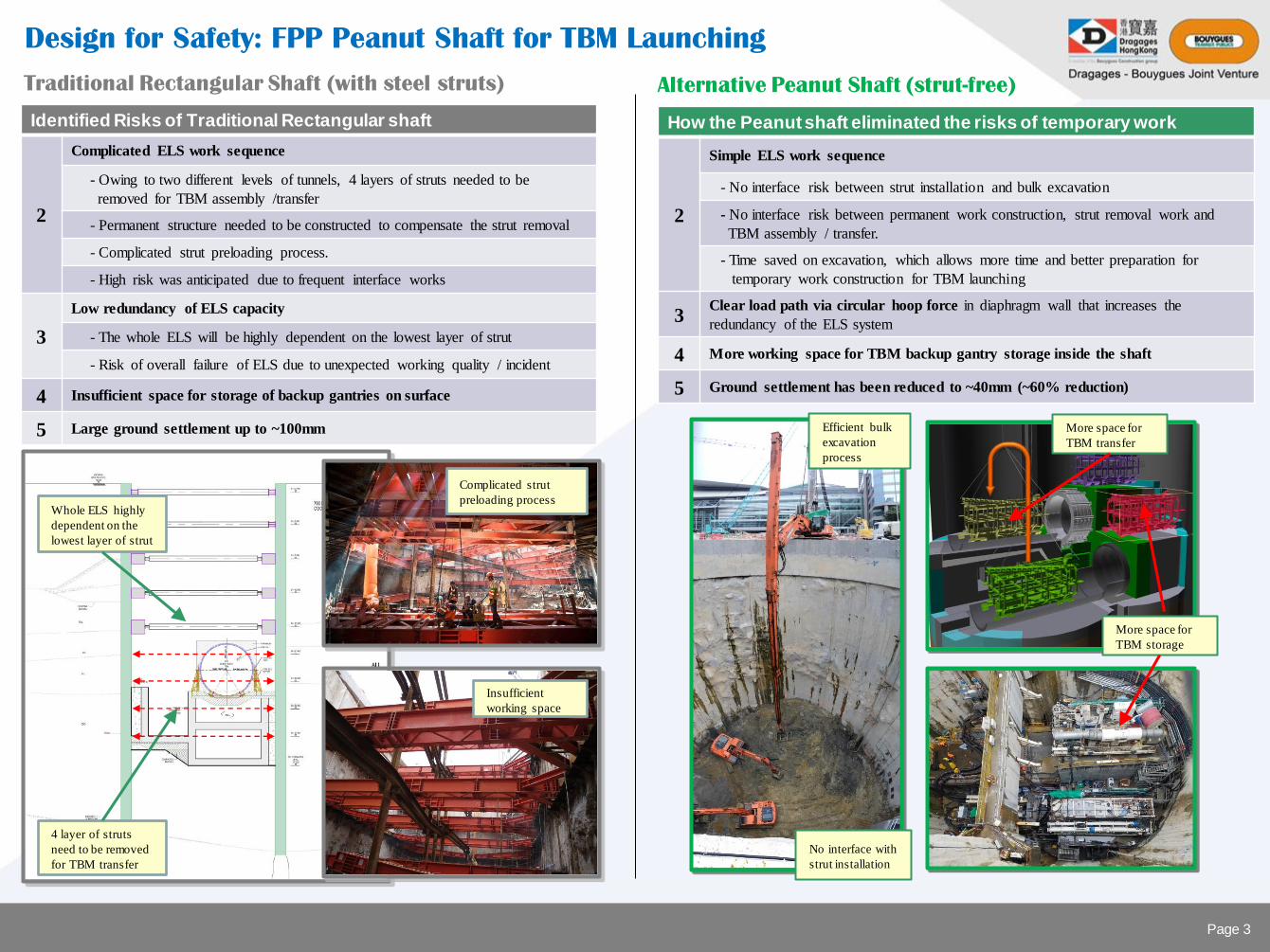
Identified Risks of Traditional Rectangular shaft
2
Complicated ELS work sequence
- Owing to two different levels of tunnels, 4 layers of struts needed to be
removed for TBM assembly /transfer
- Permanent structure needed to be constructed to compensate the strut removal
- Complicated strut preloading process.
- High risk was anticipated due to frequent interface works
3
Low redundancy of ELS capacity
- The whole ELS will be highly dependent on the lowest layer of strut
- Risk of overall failure of ELS due to unexpected working quality / incident
4 Insufficient space for storage of backup gantries on surface
5 Large ground settlement up to ~100mm
Traditional Rectangular Shaft (with steel struts) Alternative Peanut Shaft (strut-free)
How the Peanut shaft eliminated the risks of temporary work
2
Simple ELS work sequence
- No interface risk between strut installation and bulk excavation
- No interface risk between permanent work construction, strut removal work and
TBM assembly / transfer.
- Time saved on excavation, which allows more time and better preparation for
temporary work construction for TBM launching
3 Clear load path via circular hoop force in diaphragm wall that increases the
redundancy of the ELS system
4 More working space for TBM backup gantry storage inside the shaft
5 Ground settlement has been reduced to ~40mm (~60% reduction)
4 layer of struts
need to be removed
for TBM transfer
Whole ELS highly
dependent on the
lowest layer of strut
More space for
TBM transfer
More space for
TBM storage
Complicated strut
preloading process
Insufficient
working space
Efficient bulk
excavation
process
No interface with
strut installation
Design for Safety: FPP Peanut Shaft for TBM Launching
Page 3
Permanent work (staircase)
above can be delinked from
tunneling work
Selection of structural form: Innovative TBM Launching Structure
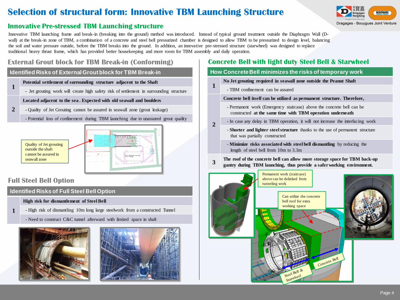
Identified Risks of External Grout block for TBM Break-in
1 Potential settlement of surrounding structure adjacent to the Shaft
- Jet grouting work will create high safety risk of settlement in surrounding structure
2
Located adjacent to the sea . Expected with old seawall and boulders
- Quality of Jet Grouting cannot be assured in seawall zone (grout leakage)
- Potential loss of confinement during TBM launching due to unassured grout quality
External Grout block for TBM Break-in (Conforming) Concrete Bell with light duty Steel Bell & Starwheel
How Concrete Bell minimizes the risks of temporary work
1 No Jet grouting required in seawall zone outside the Peanut Shaft
- TBM confinement can be assured
2
Concrete bell itself can be utilized as permanent structure. Therefore,
- Permanent work (Emergency staircase) above the concrete bell can be
constructed at the same time with TBM operation underneath
- In case any delay in TBM operation, it will not increase the interfacing work
- Shorter and lighter steel structure thanks to the use of permanent structure
that was partially constructed
- Minimize risks associated with steel bell dismantling by reducing the
length of steel bell from 10m to 3.3m
3 The roof of the concrete bell can allow more storage space for TBM back-up
gantry during TBM launching, thus provide a safer working environment.
Quality of Jet grouting
outside the shaft
cannot be assured in
seawall zone
Full Steel Bell Option
Identified Risks of Full Steel Bell Option
1
High risk for dismantlement of Steel Bell
- High risk of dismantling 10m long large steelwork from a constructed Tunnel
- Need to construct C&C tunnel afterward with limited space in shaft
Can utilize the concrete
bell roof for extra
working space
Innovative TBM launching frame and break-in (breaking into the ground) method was introduced. Instead of typical ground treatment outside the Diaphragm Wall (D-
wall) at the break-in zone of TBM, a combination of a concrete and steel bell pressurized chamber is designed to allow TBM to be pressurized to design level, balancing
the soil and water pressure outside, before the TBM breaks into the ground. In addition, an innovative pre-stressed structure (starwheel) was designed to replace
traditional heavy thrust frame, which has provided better housekeeping and more room for TBM assembly and daily operation.
Innovative Pre-stressed TBM Launching structure
Page 4
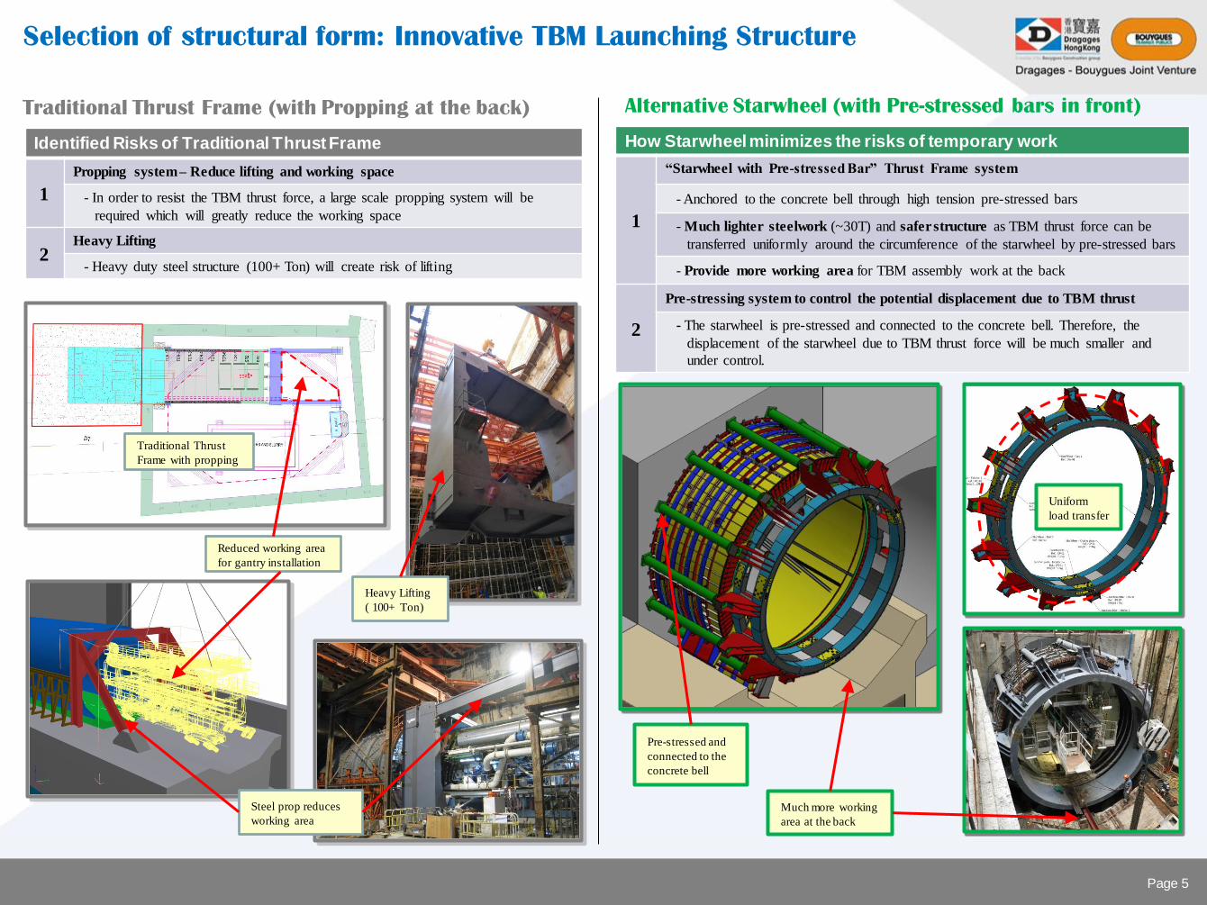
Identified Risks of Traditional Thrust Frame
1
Propping system – Reduce lifting and working space
- In order to resist the TBM thrust force, a large scale propping system will be
required which will greatly reduce the working space
2 Heavy Lifting
- Heavy duty steel structure (100+ Ton) will create risk of lifting
Traditional Thrust Frame (with Propping at the back) Alternative Starwheel (with Pre-stressed bars in front)
How Starwheel minimizes the risks of temporary work
1
“Starwheel with Pre-stressed Bar” Thrust Frame system
- Anchored to the concrete bell through high tension pre-stressed bars
- Much lighter steelwork (~30T) and safer structure as TBM thrust force can be
transferred uniformly around the circumference of the starwheel by pre-stressed bars
- Provide more working area for TBM assembly work at the back
2
Pre-stressing system to control the potential displacement due to TBM thrust
- The starwheel is pre-stressed and connected to the concrete bell. Therefore, the
displacement of the starwheel due to TBM thrust force will be much smaller and
under control.
Much more working
area at the back
Reduced working area
for gantry installation
Heavy Lifting
( 100+ Ton)
Steel prop reduces
working area
Pre-stressed and
connected to the
concrete bell
Uniform
load transfer
Selection of structural form: Innovative TBM Launching Structure
Traditional Thrust
Frame with propping
Page 5
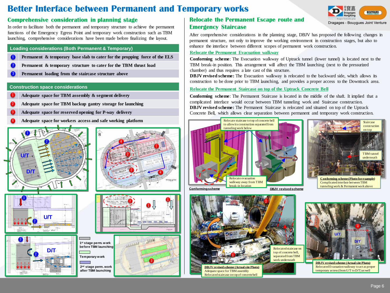
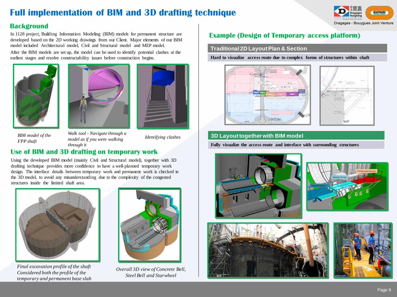
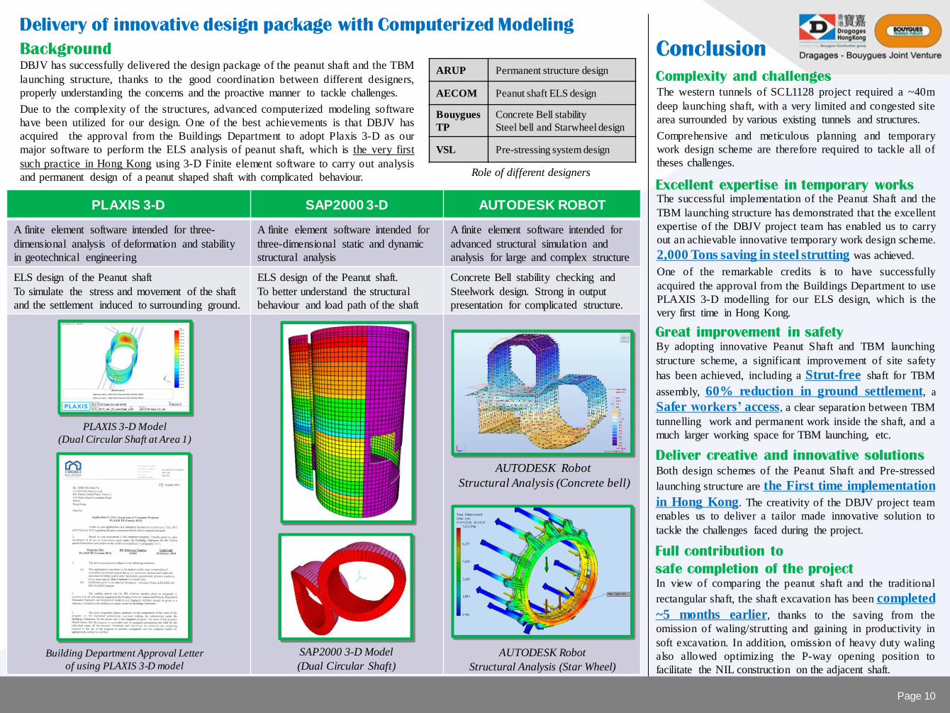
Better Interface between Permanent and Temporary works