This TWfAU Guidance is available as a free download. Website: https://twf.engineersaustralia.org.au Email: [email protected]Temporary Works Risk Guidelines Recommendations for clients, designers, their representatives, program managers and others on the definition of temporary works and the associated risks.
Transcript
This TWfAU Guidance is available as a free download.
Temporary Works forum Clients’ guide to temporary works – TWfAU2020: 01
2 Return to the contents
`
The Temporary Works forum Australia (TWfAU) will be formed in 2020 as a community of practice within Engineers Australia once we have enough content.
The following information hereafter has been extracted and adapted from the TWf (2014) with their permission. The content has been significantly unaltered as our intention is to make it more widely available by removing the prescriptive responsibility allocations required in the UK construction industry. Please note that some references to BS 5975 have been left in as an informative reference as an equivalent standard for temporary works has not been developed in Australia
Synopsis
There is currently limited guidance in Australia in relation to the topic of temporary works despite the increasing importance placed on the design and implementation of temporary works by the Australian construction industry. This guidance has been prepared to promote awareness of the potential risk mitigation, discussion, as well as to provide an insight into, the subject of temporary works and its associated risks and procedures. This guidance provides minor development to the Clients’ guide to temporary works (TWf 2014). This guidance also removes many of the prescriptive allocation of roles and responsibilities included in the clients guide to temporary works as required under the United Kingdom’s Construction (Design and Management) Regulations 2015 (CDM 2015).
Australian Setting
Temporary works in Australia is currently regulated under the work, health and safety (WH&S) framework that differs across each state in Australia.
The framework at each state consists of: an overarching WH&S Act, regulation that specifies requirements for particular hazards and risks, codes of practice that provide practical guides on satisfying the legislative framework as well as a regulator that takes care of the administration of the WH&S framework.
However, the current WH&S framework in Australia provide limited guidance on the safe design of temporary structures and does not distinguish between temporary and permanent structures and holistically falls under the definition of a ‘structure’.
Foreword
Temporary Works forum Australia acknowledges the contribution made by initial members of the working party in the preparation of this guidance in the United Kingdom.
Although the Temporary Works Forum does its best to ensure that any advice, recommendations and information it may give either in this publication or elsewhere are accurate, no liability or responsibility of any kind (including liability for negligence) howsoever and from whatsoever cause arising, is accepted in this respect by the Forum, its servants or agents.
Readers should note that the documents referenced in this guidance note are subject to revision from time to time and should therefore ensure that they are in possession of the latest version.
About the Authors
Bill Hewlett, MA CEng FICE FIET, Lead author
Bill started his career at contractor Costain Ltd in 1980, working on marine civil engineering projects and the restoration of historic structures. It was in this environment that he began designing temporary works, an aspect of the profession he has worked on and developed throughout his career. He is currently Technical Director of Costain Group PLC and Chairman of the Temporary Works Forum.
Richard Hare-Winton, BSc(Hons) CEng MICE, Author
Richard commenced his career in 1975 at contractor Higgs and Hill working on a mixture of building and civil engineering projects. Throughout his career his responsibilities have included the design, management and supervision of temporary works. He is currently Director of Technical Services at BAM Construct UK Ltd, a position he has held since 1998.
Andrew Barnes, MEng CEng MICE AMIDE, Author
Andrew began his career at Bovis Construction Limited in 1996 and has worked on a number of technically challenging projects incorporating demolition, ground works, historical restoration and new build. Since leaving Bovis he has continued to specialise in the field of temporary works design and management working for main contractors, demolition contractors and engineering consultancies. He is currently Associate Director at Swanton Consulting.
Modified for use outside UK
Rahsn Witt, BE (Hons), MEngSci, MIEAust, RINA, Editor
Clients’ guide to temporary works – TWfAU2020: 01
Temporary Works forum
Return to the contents 3
Purpose of this document
The purpose of this Guide is to assist clients, designers and their representatives,1 programme managers and other senior leaders in the construction industry in the improvement of risk control and performance on their projects.
Temporary works form a vital part of all construction projects. They can form a significant part of the works required to complete the permanent works, especially in the infrastructure space. During the construction of the permanent structure, temporary works are implemented to ensure the newly constructed permanent structures are supported in their temporary state. Why is this important? Because a significant proportion of the project’s construction cost could be spent on temporary works and their risk profile is very different to permanent works. The safety of construction workers, the greater public and others who may be affected by the temporary works must be protected at all times. It is also important to note that temporary works structures should be engineered and should be treated with the same attention and care as permanent works.
Definitions of temporary works are as follows:
• Parts of the works that allow or enable construction of, protect, support or provide access to, the permanent works and which might or might not remain in place at the completion of the work.
• BS 5975 (B/514/26, 2019) at Clause 5.1.1.1: “Temporary works can be described as providing an “engineered solution” that is used to support or protect either existing structure or the permanent works during construction, or to support an item of plant or equipment, or the vertical sides or side-slopes of an excavation during construction operations on site or to provide access. It is used to control stability, strength, deflection, fatigue, geotechnical effects and hydraulic effects within defined limits.”
• The Temporary Works Forum (TWf) Client's Guide to Temporary Works (TWf, 2014) : “states of the permanent works which are temporary, loading conditions of the permanent works during construction or project execution which [sic] not envisaged in the permanent condition, structures in states of modification or demolition”.
When it comes to categorisation of temporary works, there are a lot of publications around the globe that explain how temporary works can be classified or categorised. Their forms can be very different as a high-rise building, bridge, tunnel or shaft construction requires very different techniques to build them. A relatively easy way to differentiate them could be done based on the following:
• Earthworks: temporary berms and cuttings, excavations, trenches, temporary slopes, temporary access roads, etc.
1 For simplicity only the terms ‘client’ and ‘client’s representative' are used in the remainder of the text.
• Structures: site hoardings, scaffold, formwork, falsework, shoring, retaining walls, waling and propping, shafts, cofferdams, heavy lift systems, etc.
• Equipment/plant: tower crane foundations, hoist foundations and ties, hardstands for bentonite plant, any work to support plant and machinery (e.g. piling rig, diaphragm wall drilling rig and mobile crane working platforms, mobile crane and concrete mobile pump outrigger support)
• Structures in the temporary condition: permanent works structures during construction that are unstable or have insufficient strength, and structures during demolition and dismantling (e.g. those subject to pre-weakening).
It is hoped that it will be of use to all clients, designers and senior managers, of both large and small scale works, whether they are involved regularly with construction, or seldom, including those whose normal work is not construction but are nonetheless procuring construction works.
Contents
To navigate to page - hover over an item below and ‘click’. Return to contents by clicking on the ‘Return to the contents’ at the bottom of every page.
Section Page
Purpose of this document ......................................... 3 Introduction: The role of the client ........................... 4 Article 1 – Risk Categorisation ................................. 7 Article 2 – Good Temporary Works Design ........... 11 Article 3 – Good Temporary Works Design
Checking ................................................................... 18 Article 4 – Good Temporary Works Site Inspection
works and permanent works ................................... 24
Temporary Works forum Clients’ guide to temporary works – TWfAU2020: 01
4 Return to the contents
`
Introduction: The role of the client
The client is the body who the work is carried out for.
With regard to temporary works the most important roles
of the client are:
• Select and appoint a competent Principal
Contractor
• Ensure that the designers are competent
• Ensure that suitable management arrangements are
made for the project
• Ensure that appropriate Work Health and Safety
systems are established and that they contains
suitable management controls for temporary works
• Ensure sufficient time and resources are allowed for
all stages of the project
• Provide temporary works designers with a
temporary works design brief, see 2.1.1
• Facilitate third party reviews of temporary works
designs were required, see Article 3.
For a client to be assured that these duties are fulfilled in
regard to temporary works, it is natural that the client’s
representatives will need to know what temporary works
are, and what competencies are appropriate, and as such
are referred to this document.
However, for the client’s role to be fully appreciated we
must think also about why temporary works are needed,
and add a more philosophical dimension to this physical
definition: temporary works are needed to control the
residual risks arising from temporary conditions during
project execution.
It is a requirement that risks are reduced ‘so far as
reasonably practicable’ (SFARP). The recommended
hierarchy of control to achieve this is by (first) elimination
of the hazard (for instance the permanent works are
designed in such a way that temporary conditions are
avoided), elimination of the temporary works (the
permanent works are designed in such a way that no
temporary works are required to stabilise or support
them in temporary conditions), then substitution (a safer
type of temporary works is required or provided),
reduction (less temporary works, or at any rate less
temporary works at any one time), then lastly design
improvement of any temporary works that remain.2
While safety principles drive us towards elimination or
reduction of temporary works, so too should
considerations of cost and time.
2 In pursuing these hierarchies it is important that benefits in reducing risks from temporary works (for instance by eliminating them) do not increase risk in another area (for example by making the permanent works erection more risky). There is arguably a ‘right amount’ of temporary works for a given scheme, which is the amount that reduces the risk overall so far as reasonably practicable; to assess these risks ‘overall’ requires that the temporary conditions of the permanent works, the construction method and the temporary works themselves are considered as one, collectively 3 A ‘sensitivity’ can be thought of as a particular aspect of the design of the character that if all is done exactly as it should be (given the margins that engineering tolerances allow) all will be fine, but if anything is done even slightly not-exactly-as-it-should-be (for example slightly out of tolerance or not exactly to plan) an incident will result. Sensitivities are the opposite of robustness. Sensitivities introduce risk as even the best performers will step outside the allowable envelope from time to time. As a rule, sensitivities should be avoided. However, some designs benefit in the long term from sensitivities during construction. Where this is the case, designers should justify introducing the sensitivity and should ensure it is fully communicated to (including being understood by) the project procurement and construction team. The IStructE publication, Manual for the systematic risk assessment of high-risk structures against disproportionate collapse gives good guidance in this area (ISE, 2013). 4 The appropriate party will vary according to the risk and is usually held to be the party most able to manage it, which may vary with time. The risks associated with a project need management throughout concept development, design, planning, procurement (by client to advisors, by client to Tier 1 suppliers, and by Tier 1 to Tier 2 suppliers, etc) and execution of the works. Those managing risks need appropriate financial and time allowances and client’s representatives should satisfy themselves on this point also, and ensure this consideration is active at all levels of the supply chain 5 For example it is generally harder to achieve temporary works safety if the permanent works are procured as a number of separate works packages, as opposed to a single contract; consider also that a procurement strategy that seeks fees and prices to be at a bare minimum may tend to exclude the broader professional engagement amongst the parties to the works, which this Guide identifies as aiding temporary works safety
Temporary works are expensive, take time to design and
build, and bring their own hazards. From these
considerations we can see that it is in the client’s interest
that design teams include people and organisations who
have practical and contemporary understanding of the
construction process and temporary works appropriate
to the works proposed. The design team will then be able
to design a solution which ideally eliminates, but
certainly reduces and simplifies, the temporary works;
for the temporary works that remain, the team can
ensure that there are safe and economic solutions, and
that the scope and full performance specification for the
temporary works are communicated to those who will
design and use them.
In seeking to ensure that clients’ interests are served
with regard to temporary works, their representatives
could usefully challenge themselves with the following
questions:
• In what way can I be assured that the permanent
works design solution is developed to minimise risk
from temporary conditions?
• In what way can I be assured that those temporary
conditions of the permanent works that need
temporary works to control them minimise the
extent and complexity of the temporary works,
eliminating, substituting and reducing them so far
as reasonably practicable to minimise the risk
overall?
• In what way can I be assured that the requirements
for temporary works will be communicated
effectively, with all criteria for performance,
including sensitivities?3
• In what way can I be assured that the risks from the
temporary conditions and temporary works are
appropriately allocated and managed, in particular
that the temporary conditions and temporary works
will be managed competently and safely on site?4
• In what way can I be assured that the resources
deployed (at all stages, including design of both
permanent and temporary works) have the
competence, time and resources to do the above?
How can I be assured that the structuring of the
procurement strategy, and the influences that are
applied, are not deleterious in any way to
temporary works safety?5
Clients’ guide to temporary works – TWfAU2020: 01
Temporary Works forum
Return to the contents 5
The challenges above can be drawn from Table 2, where
the evolution of a design for a project is set out. The four
Articles into which this document is divided give insight
to assist clients and their representatives to pursue
these challenges more fully, gauge risk appropriately
and understand ‘what good looks like’.
The over-riding point is that projects should be designed
and resourced to be built safely, efficiently and to the
right standard. This is an interpretation of the design- for-
manufacture principle of production industries. The
resulting benefits of safety, efficiency and quality are
worth having, but require a proactive engagement
between all parties to the design, construction and
operation.
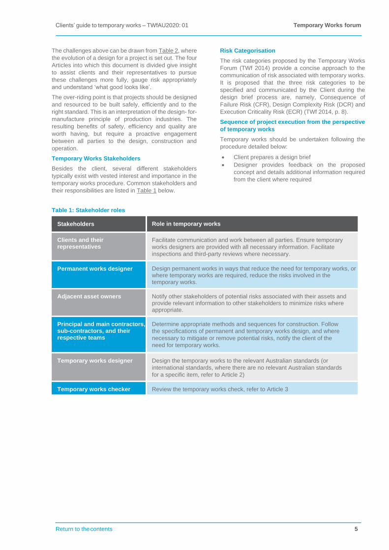
Temporary Works Stakeholders
Besides the client, several different stakeholders
typically exist with vested interest and importance in the
temporary works procedure. Common stakeholders and
their responsibilities are listed in Table 1 below.
Risk Categorisation
The risk categories proposed by the Temporary Works
Forum (TWf 2014) provide a concise approach to the
communication of risk associated with temporary works.
It is proposed that the three risk categories to be
specified and communicated by the Client during the
design brief process are, namely, Consequence of
Failure Risk (CFR), Design Complexity Risk (DCR) and
Execution Criticality Risk (ECR) (TWf 2014, p. 8).
Sequence of project execution from the perspective
of temporary works
Temporary works should be undertaken following the
procedure detailed below:
• Client prepares a design brief
• Designer provides feedback on the proposed
concept and details additional information required
from the client where required
Table 1: Stakeholder roles
Stakeholders Role in temporary works
Clients and their representatives
Facilitate communication and work between all parties. Ensure temporary
works designers are provided with all necessary information. Facilitate
inspections and third-party reviews where necessary.
Permanent works designer Design permanent works in ways that reduce the need for temporary works, or where temporary works are required, reduce the risks involved in the temporary works.
Adjacent asset owners Notify other stakeholders of potential risks associated with their assets and provide relevant information to other stakeholders to minimize risks where appropriate.
Principal and main contractors, sub-contractors, and their respective teams
Determine appropriate methods and sequences for construction. Follow
the specifications of permanent and temporary works design, and where
necessary to mitigate or remove potential risks, notify the client of the
need for temporary works.
Temporary works designer Design the temporary works to the relevant Australian standards (or
international standards, where there are no relevant Australian standards
for a specific item, refer to Article 2)
Temporary works checker Review the temporary works check, refer to Article 3
Temporary Works forum Clients’ guide to temporary works – TWfAU2020: 01
6 Return to the contents
`
Table 2: Sequence of project execution from the perspective of temporary works
Key stage Primary activity Temporary works
consequences Temporary works risk action6
Identify need; client
decides to develop
the project
Assessment, review,
asset performance
studies
Fix the nature of the
solution
Review possible
options,7 design
studies
Largely fixes the inherent
risks of the project
Identify and thereby (so far as reasonably
practicable) eliminate hazards and reduce
high risk temporary conditions and states for
each option; use findings to inform the
nature of the solution; ensure a team is
assembled which is competent and
resourced to assess and manage the risks
Design the Options studies, Completes the fixing Design the permanent works to (so far as
permanent works permanent works of the inherent risks of reasonably practicable) eliminate hazards
design the project and strongly and reduce the risks and costs from
constrains the methods temporary conditions and temporary works;
that can be used to set out the information needed to control
eliminate, reduce and the significant residual risks; Principal (or
control them; largely Main) Contractor and supply chain to be
fixes the inherent risks of competent and resourced to manage the
the temporary works risks
Design the Temporary works Completes the fixing Follow through on the inform/control of
temporary works co-ordination; of the risks inherent in residual risks from above; design the
temporary works the temporary works; temporary works to (so far as reasonably
design & design finalises the methods to practicable) eliminate hazards and reduce
checking control the residual risks the risks and costs; set out the information
of the temporary states needed to control the residual risks and
of the permanent works allocate management responsibility; ensure
design the temporary works have an appropriate
maintenance and inspection regime, and
that the design includes safe accesses for
this
Execute the Temporary works Monitor emerging Execute the works in a controlled manner, temporary works co-ordination; site conditions to ensure the to ensure what has been designed is
inspection; control designs remain relevant; what is built; follow through on the inform/
by permits if the design must be control and management of residual risks
changed the full control from above; risk assess all activity, allocate
of the design process management responsibility and oversee
must be used performance; ensure competence of all
involved and confirm as adequate the
resource level of the team
6 Risk actions (in order) are to are to eliminate hazards, reduce risks, inform others of & control the residual risks (the ‘ERIC’ formula, which is sometimes extended by adding ‘protect people and instil disciplines of activity’: ‘ERICPD’); these may be achieved by eliminating temporary conditions, eliminating temporary works, substituting a lower risk form of temporary works, reducing the amount of temporary works (certainly at any one time), designing improvements to the temporary works and implementing appropriate exclusion zones, processes and protective equipment 7 Options studies at this level are beyond the scope of this document. A part of these option studies must be, however, an assessment of the relative hazards. As the options could be of radically different type (for example, infrastructure needs are being met increasingly by control engineering solutions such as variable speed control on motorways which reduces the need to construct new carriageway space) these relative hazard studies are clearly not straightforward, and different alternatives could be safer in some ways but more hazardous in others. This document relates to hazards as encountered when physical works (routinely thought of as building, construction, civil or structural engineering, and involving new build, modification of existing works, demolition etc) are being planned or undertaken. That is not to say that such activities are not encountered across a broad range of industries, as excavation or temporary supports to structures are encountered as much in the power and petrochem sectors, for instance, as they are in a traditional civil engineering context such as motorway or rail construction
Clients’ guide to temporary works – TWfAU2020: 01
Temporary Works forum
Return to the contents 7
Article 1 – Risk Categorisation
1.1.1. Inherent Risk
In 1828, Thomas Tredgold gave an influential definition of civil engineering, in which he identified a civil engineer’s work to be ‘the art of directing the great sources of power in nature for the use and convenience of man’.
The concept of entropy was not defined at the time, and Tredgold’s line of thought might have led him to a slightly different position had it been: the work of a construction professional today, to echo Tredgold’s words, can be thought of as being ‘to concentrate energy for use and convenience’.
The issue at hand, and the relevance of concentrated energy, is that concentrated energy will tend to disperse and even out with its surroundings in time. The consequences are, for example, that structures we erect tend to fall down, water we hold in a reservoir will tend to break out and flow down, substances we pressurise will tend to break out and disperse, vehicles we constrain to move along tracks or specific paths will tend to come off them and, should they do so, may crash catastrophically.
The first merit of this line of thinking is that by recognising where we have locally concentrated energy we recognise where we have a potential for failure: a hazard. The greater the concentration of energy, the greater is the scale of the potential failure. This guides us in our hazard identification.
The second merit is that by recognising that nature is tending to make things fail, we focus our efforts on ensuring that this does not occur during the planned service life of the works we are constructing. We are, in a sense, playing a waiting game with nature: in the long term the natural degradation of materials will cause our works to fail; in the short term errors or omissions will cause failure during the course of construction work. By taking the position that ‘failure is inevitable, the question is when’, we never assume that the worst cannot happen. Commentators in the field of forensic engineering regard this to be a healthy state of mind, despite its negativity (Petroski, 2014; Weick and Sutcliffe, 2007, Haddon-Cave n.d.; ISE, 2013).8
Focussing back onto temporary works we can see that
• Any weight at height will lose height unless prevented (this includes things falling over sideways then down as well as straight down, and the soil forming the side of excavations sliding into the excavation)
• Any materials separating zones of different pressure in a fluid will move towards the area of low pressure unless prevented (pressure differences can be caused by flowing water, wave action, wind etc, and are often normal to the direction of flow)
• Materials will float (or partially float, losing interface friction) if water levels rise, unless prevented
• Any forced segregation of fluids will mix unless prevented
• Any forced concentration of fluids will disperse unless prevented
8 See, for instance, Petroski (2014); Weick and Sutcliffe (2007); Sir Charles Haddon-Cave’s address to the Institution of Civil Engineers on 19 November 2013; and ISE (2013), which gives a highly practical methodology for risk management 9 Appendix B explores this topic further
• Any forced combination of materials will separate unless prevented
• Any pressurised fluid will leak out unless prevented
• Any volume under pressure will expand unless prevented
• Where we are alongside high energy sources, accidentally interfering with them can cause problems which are disproportionate to the failure we are managing directly (for example a hoarding, if blown over, could fall onto a road or railway line and cause a major incident)
The construction industry serves our society’s need for tall structures, underground structures, energy efficient high pressure and high voltage fluid and electrical systems, high speed transportation, containment of dangerous but useful chemicals, and so forth. These needs create inherent risk in the form of large masses at height, high pressure, high voltage, high kinetic energy, huge masses of soil either side of deep excavations, extreme concentration of toxins and so forth.
We should bear in mind that all structural materials (eg steel, concrete, timber, even rock) require a concentration of energy (whether through their manufacture or by natural process) and will therefore tend to degrade. This degradation can be the trigger for failure at a much bigger scale.
The risks in the operational phase of a facility will be identified through hazard studies. Often less attention is given to the construction phase, but these facilities cannot be wished into place: they must be methodically constructed, stage by stage. The inherent risks in the temporary conditions are much the same as in the permanent condition (the loads, potential energy and so forth are the same, as are the potential impacts on adjacent assets) but there are added difficulties with temporary works, both
• inherently: o the materials used must be handleable, often
man-handleable o the temporary structures must be self- stable as
well as supporting the permanent works in temporary conditions
o as the temporary structures are designed (usually) for a known and one-off load, they are highly stressed in service
o access must be provided for construction personnel, and prevent falls of them, their tools, small parts, etc
o the site configuration is constantly evolving
• and from the prerogative for efficiency and economy:
o the use of standard equipment, used many times
o structural forms which are often highly indeterminate, but are nonetheless of a type that a single seemingly insignificant component can be critical to the stability of the whole
o the time and cost pressures arising from the contractual circumstances
Perhaps the one saving grace is that temporary works are (in many cases) loaded under the supervision of the teams that design and build them. However, even this cannot be relied upon.9
Temporary Works forum Clients’ guide to temporary works – TWfAU2020: 01
8 Return to the contents
`
1.2. Risk Categorisation
1.2.1. Consequence of Failure Risk
The consequences of a failure can be radically different according to circumstances. The failure of a minor excavation in a remote location for a task which requires no man-entry is different entirely from a similar excavation failing such that it undermines a main line railway or pressurised tank of noxious chemicals. In essence, the Consequence of Failure Risk (CFR) requires consideration of what could happen if things go wrong, bearing in mind that we should never think that the worst cannot happen. Four categories of CFR are proposed, see Table 3.
Consequence of Failure Risk (CFR therefore springs from the nature of the works to be carried out, the location of the works and what is in proximity such that it might be affected if failure of the temporary works occurs. This may be time dependent.
A number of parties need to consider CFR, for instance:
• Clients and their Representatives (for example when establishing the basis of risk control and ensuring the competence of key parties)
• Permanent works designers (for example when determining site location, the nature of the works to be constructed, and when assessing risk potential within a site)
• Adjacent asset owners (they should be involved as they have best knowledge of potential risks should temporary works failure have influence beyond the site boundary)
• Principal and Main Contractors, sub-contractors, and their respective teams (for example when determining methods and sequences of construction and carrying out works)
Table 3: Categories of Consequence of Failure Risk
Categories Characterisation of consequence of failure
CFR0 benign, no impact if it fails
CFR1 low impact and entirely within site; inconvenient but personal injury unlikely
CFR2 potentially major effect, but failure, while potentially of major impact (for
instance involving fatalities and injuries +/or significant economic loss) would
not initiate any secondary or chain reaction of major incidents
CFR3 failure, should it occur, would be catastrophic in its own right or, even if
minor in its own right, might initiate a secondary or chain reaction of major or
catastrophic incidents
Clients’ guide to temporary works – TWfAU2020: 01
Temporary Works forum
Return to the contents 9
1.2.2. Design Complexity Risk (DCR)
Design Complexity Risk (DCR) is treated, in effect, in BS5975. The Standard does this by recommending four Categories of design checking regime (0, 1, 2 & 3) as the risk control. This Guide endorses this principle and adopts the four Categories but adds two more: Category 00 and Category 4.
Category 00 is for temporary conditions, items or structures which can be safely managed by competent persons in competent site teams, without design, by following custom and practice and an industry standard safe system of work. Such parts of the works might include kicker shutters, shaping of the ground and so forth.
The safe system of work will normally include risk assessments which focus on the operation at hand in its context, method statements and supervision. Category 4 is for temporary works which have abnormal and highly innovative designs, beyond the scope of normal design codes and practices.
This Guide also recommends that CFR, see Table 3, is a factor which should be taken into account in considering DCR; six Categories are recommended, see Table 4.
The design and design checking procedures in respect of these categories are set out in Articles 2 and 3.
Table 4: Design Complexity Risk
Category Characterisation of design10
DCR00
temporary conditions, items or structures which can be safely managed by competent persons in
competent site teams, without design, by following custom and practice and an industry standard
safe system of work, provided Consequence of Failure Risk is CFR0 or CFR1 (Table 3 refers)
DCR0 standard solutions11 provided Consequence of Failure Risk is CFR0 or CFR1
DCR1 simple designs provided Consequence of Failure Risk is CFR0 or CFR1
DCR2
more complex or involved designs provided Consequence of Failure Risk is CFR2 or below; also
designs with Design Complexity Risk DCR00, DCR0 or DCR1 either with Consequence of
Failure Risk CFR2 or where there is interaction between adjacent but separately managed
schemes12 (or both)
DCR3 complex or innovative designs which result in complex sequences provided Consequence of
Failure Risk is not CFR3
DCR4 abnormal and highly innovative designs beyond the scope of normal design codes and practice;
also any scheme with Consequence of Failure Risk CFR3
10 For categories DCR0, DCR1, DCR2 & DCR3 refer BS5975 Table 1 Categories 0, 1, 2 & 3; in BS5975 ‘standard solutions’ are defined: ‘a suitable arrangement of components for which the basic design work has already been carried out and is presented in a tabular or other easily assimilated form, and for which no further structural calculations are necessary’ 11 It is the authors’ experience that relatively few schemes are Design Complexity Risk category DCR0 in their entirety; even routine schemes need foundations, and interaction with natural earth can seldom be a ‘standard solution’ in the definition of BS5975 (see footnote1 also) 12 For example it is generally harder to achieve temporary works safety if the permanent works are procured as a number of separate works packages, as opposed to a single contract; consider also that a procurement strategy that seeks fees and prices to be at a bare minimum may tend to exclude the broader professional engagement amongst the parties to the works, which this Guide identifies as aiding temporary works safety
Temporary Works forum Clients’ guide to temporary works – TWfAU2020: 01
10 Return to the contents
`
1.2.3. Execution Risk (ER)
Execution Risk (ER) is a measure of the propensity for failure resulting from issues related to use, workmanship and/or materials. ER is therefore influenced by design but its management and control requires appropriate care and attention both in materials procurement and on site, at all stages of erection, assembly, use, operation, maintenance, disassembly and removal. This Guide proposes four categories, see Table 5.
It is considered essential that temporary works designers make clear in their design output the controls and hold points they consider necessary to ensure the ER can be adequately managed by those procuring, constructing, using and removing the temporary works. Of course, further controls and hold points may be added by the construction teams.
1.2.4. Managing Consequence of Failure, Design Complexity and Execution Risks
In all cases, all stakeholders should seek to eliminate foreseeable hazards to the health and safety of those affected and to mitigate those risks which cannot be avoided.
The three types of risk identified (CFR, DCR and ER) should be actively managed and reduced throughout the design process. The permanent works design phase gives the greatest scope of opportunity: once the permanent works scheme is chosen, the CFR is effectively fixed, and the scope to reduce DCR and ER becomes limited.
Throughout the planning, design, procurement, and construction phases a formalised risk management procedure should ensure the clear allocation of responsibility for risk management. Such a procedure will ensure that risks are addressed adequately by the appropriate party, with appropriate financial and time allowances.
The level of CFR, with explanation, should be given in the two part Temporary Works Brief Table 6. This information will be important to the temporary works design, design checking, procurement, and operations teams.
To allow CFR to play its part, while keeping the document simple, it is assumed, where there is high CFR, that designers will increase the category of DCR, and operations teams will increase the category of ER. Suggested adjustments are given in Tables 3 and 4.
Designers (both temporary works designers and permanent works designers) have the opportunity to eliminate hazards and mitigate risks and inefficiencies by design. As a generality this implies that all requirements for temporary works should be minimised. Where temporary works are required, the design should be developed to minimise the categories of CFR and ER.
Those on site have the opportunity to eliminate hazards and mitigate risks by practical means, especially by ensuring control and good quality workmanship, and by using methods that minimise the exposure of personnel to hazardous environments.
1.2.5. Other risks
This section focuses on specific aspects of the risk management of temporary works from the perspective of the works themselves: what is their situation, what is their complexity, how critical is their workmanship. In parallel with this must be a consideration of the other generic risks arising, for instance from the competence of the people involved and the quality of the processes used (for example to design, to check, to review, to procure, to validate software etc). This is illustrated in the IStructE publication ‘Manual for the systematic risk assessment of high-risk structures against disproportionate collapse’ (ISE, 2013)
Table 5: Categories of Execution Risk (ER)
Category Characterisation of the propensity to failure during erection, assembly,
use, operation or removal
ER0 no identified practical mode of failure, and Consequence of Failure Risk is
CFR2 or below even if it did fail
ER1 minor structures with high levels of robustness and redundancy provided
Consequence of Failure Risk is not CFR3
ER2 conventional structures provided Consequence of Failure Risk is CFR2 or
below
ER3
schemes with dependency on critical structural details or tension details, or
with little or no redundancy or with inherent instability; also any scheme with
Consequence of Failure Risk CFR3
Clients’ guide to temporary works – TWfAU2020: 01
Temporary Works forum
Return to the contents 11
Article 2 – Good Temporary Works Design
2.1. Introduction
A good temporary works designs are characterised by the following:
• they are simple and safe to fabricate, erect, check once erected, use and remove, careful thought has been given to these matters
• they are each a single, fully co-ordinated design in which all relevant aspects of the structural system are considered13
• they are robust and are sufficient as structures in their own right; also they have safe access for inspection and maintenance and, where needed, an appropriate inspection and maintenance regime
• the designer’s intent is communicated fully and without ambiguity
• the basis of each design is clear to those who will manage each individual scheme, and to those who will manage the overall project, so that they will identify and pay proper attention to the safety and performance-critical features; they will know and respect all sensitivities of the design; they will know what changes in circumstances would invalidate the design
Good design requires a considered, early appointment and briefing of the designer. A good appointment will be based on sufficient knowledge of the design work to be conducted: in principle the designer needs to know what has to be done and be comfortable that the time, resources and budget are available to do it. If it is not possible to achieve this position at the outset, a two-stage (or multi-stage) process should be used to agree scope and price progressively. A good appointment will ensure that the designers who will undertake the work are suitably qualified and experienced, and that they are properly supported by the management processes of their organisation; the design organisation, as well as individual designers, must be competent in the type of work. Early temporary works designer appointments will maximise the designer’s contribution to the design concept and ideally to the design of the permanent works, so that the permanent works scheme is adapted to a safe, efficient construction methodology and temporary works. A formal peer review of the permanent works concept, involving construction method and temporary works experts, will normally pay dividends.14
13 This must be achieved even where various parts of a single structure are prepared by different designers, or there are independently procured but interacting structures. For instance a falsework may be designed by an equipment supplier but stand on a suspended slab designed by the permanent works designer, be stabilised in sway by columns in a temporary condition which is the design responsibility of the concrete frame contractor, and have a timber deck designed by a fourth party; it is possible that lateral stability develops a load path to a neighbouring site, or ground support introduces soil stresses beyond the site boundary. See Section 4 on design checking. While designers should take a holistic view, this is not always realistic given the current procurement structures and commercial pressures. Clients and their representatives should consider if their procurement strategies tend to enhance or be deleterious to considerations of this type 14 See references for SCOSS documents (SCOSS 2009a, SCOSS 2009b)
The majority of temporary works are designed during the construction phase of the project. In some circumstances the temporary works will be designed by, or on behalf of, the Principal (or Main) Contractor directly. In many circumstances, the temporary works designs will be prepared by, or on behalf of, sub-contractors whose sub-contract package includes temporary works design. In all cases, the temporary works designers may be internal or external to the organisation with contractual responsibility for the works themselves. Where design is procured as a part of a broader sub-contract, clearly the ability to deliver a competent temporary works design is a prerequisite for appointment.
It is relatively rare for clients or project managers to commission temporary works design before the construction phase. More normally they will be seeking construction advice in a broader sense. If a client or project manager does wish to commission temporary works design, the coordination should be done by someone with experience in temporary works. Another course of action is to engage a suitable contractor to provide pre-construction advice.
The following text will set out the processes for design briefing and design of temporary works and is set in four parts: design brief (3.2), concept design (3.3), detailed design (3.4), and site support (3.5).
Where a client body has its own rules for temporary works design and management, it should ensure that its rules align with best practice. An audit against this document would be a means to do this. Also, as a matter of convenience, client body rules should strive to use common terminology and processes, as single design and contracting organisations typically work for many clients at the same time.
Clearly, as design complexity increases, refer Table 4, the detail of the design process varies, becoming more and more rigorous.
A particular type of hazard emerges where the permanent works are procured as separate packages, or there is adjacency of neighbouring sites. This type of situation must be handled with particular attention as, while the schemes may be commercially independent, the structural stability of their temporary works may not be, and structural forces give no regard to commercial boundaries.
Temporary Works forum Clients’ guide to temporary works – TWfAU2020: 01
12 Return to the contents
`
2.1.1. Design Brief and Design Statement
2.1.2. Design Brief
This section applies to DCR category DCR0 and above (Table 4 refers). DCR00 does not require a design brief.
The Design Brief sets out the performance and other characteristics required of the temporary works and the information which is to be used to progress the design. This underlying basis for the design must be understood by others so that they can confirm that the design remains valid at the time at which it is used.
A Design Brief is required for all DCR categories DCR0 and above. Clearly, however, the content and detail will vary, involving relatively little work for a small and low risk scheme, to a large amount of information for major work.
Attention is drawn to the following points:
• What constitutes ‘a design’ needs careful thought. A pitfall to avoid is to break one scheme into parts and to fail to recognise interdependencies between the parts; interdependencies may be structural, or may result from proximity in location, time or sequence. Where projects include temporary works, solutions prepared by a number of temporary works designers or contractors, it is essential that they are adequately coordinated.
• All design briefs should indicate the CFR (Table 3 refers). If the CFR is Category CFR2 or CFR3, the DCR should be raised (Table 4 refers)
• It is insufficient for the Designer to be given access to a database and be expected to search for the relevant information; while stating what information is available for reference and where it can be found, the design brief must be specific as to the information to be used
• The temporary works designer requires a wide range of information. This may require more or different information than is provided in the contract documents or is otherwise available; occasionally new information may be needed which, in some cases, might be simply to confirm the accuracy of the existing information. Information about adjacent schemes may be needed which, whilst the schemes are commercially independent, their temporary works are not. The temporary works designer must review the information and, using independent judgement, assess that it is current and sufficient, or, if not, request additional information as required. All requests made by the temporary works designer for additional or confirmatory information should be passed to the Client or Project Manager for action, and must be honoured.
15 See footnote3
• Working from the design brief, and by visiting site if appropriate, the temporary works designer will make a thorough review of what is in the location of the proposed temporary works, or is close enough to affect them, or be affected by them, or may at some stage come close enough. These things may include soil conditions, excavations, other temporary works, fixed assets, vehicles passing, crowds, water, etc. How these influences on the design affect it must be clear from the brief. Where not initially clear, the temporary works designer will conclude the matter with the Client or Project Manager and make it clear by updating the Design Brief, or the Design Statement or other documents as relevant
• The Design Brief must convey to the temporary works designer a full understanding of the purpose of the temporary works, including the criteria they must fulfil, for example, in respect of loads and stiffness, any spatial constraints, the criteria that the temporary works must fulfil in the way in which they interact with the permanent works and any relevant sensitivities 15 of the permanent works solution. Where appropriate the permanent works designer should be used by the Client or Project Manager to brief the temporary works designer directly; clients must ensure that permanent works designers are enabled to do this
• The temporary works designer must be briefed on any preferences and constraints on the materials or components to be used, their delivery and handling; site access and crane handling capacity might also impose constraints
• Temporary works designer must be briefed on project timing issues; it is germane to make the temporary works designer aware also of risks and opportunities in this regard
• The design brief must make clear the requirement for safe accesses for inspection and maintenance and call for a maintenance schedule
Before the construction or design of temporary works, a design brief should be prepared by the client and reviewed by the temporary works designer to specify the details of the project scope. The brief should involve a twofold process whereby, the client shall first set out the scope of temporary works required and other necessary information, and on receipt of the brief, the temporary works designer shall provide feedback on the design requested by the client. This is a necessary process to facilitate the communication of relevant information between the client and designer in a succinct manner. The sample design brief provided in Table 6 below is an example of a comprehensive brief, with minimum requirements for alternative design briefs annotated.
Clients’ guide to temporary works – TWfAU2020: 01
Temporary Works forum
Return to the contents 13
Table 6: Return Design Brief Template
Item No.
Characterisation of design Client Scope Design Requests
Designer Response
1 Project*
2 Brief reference*
3 Description*
4 Discipline
5 Scope
6 Potential to impact public safety
7 Risk / Uncertainty assessment*
8 Constraints and Hazards
9 Preferred strategy / construction methodology / staging /
preferred and non- preferred solutions
10 Design life*
11 Requiring lifting
12 Proposed method of decommission / removal
13 Proposed loading*
14 Interfaces*
15 Program dates
16 Specification/ Design Standards
17 Functional requirements*
18 Design deliverables
19 Sketch*
20 Environmental
21 Risk
Note: * denotes minimum requirements
2.1.3. Design Statement
This section applies to DCR category DCR1 and above, see Table 4.
The Design Statement is a counterpart to the Design Brief (Designer Response in Table 6 above), together they set the basis of the design work. The Design Brief is written to confirm site specific information and performance requirements and is written to confirm the technical basis for design.
The Design Statement is to be written by the temporary works designer.
The relevant content for the Design Statement is provided in Table 6 above in the Designer Response column.
Temporary Works forum Clients’ guide to temporary works – TWfAU2020: 01
14 Return to the contents
`
2.2. Concept design
2.2.1. Concept design, option studies and
concept peer review
With the Design Brief and Design Statement confirmed, the designer can work up the design itself. This may start with a concept design, which is to test that emerging proposals meet requirements.
For a complex design, the temporary works designer will take the concept through the following stages:
1. Work up and record initial concepts 2. Review appropriate concepts with his or her
client (usually the site team), and shortlist 3. Review the shortlisted concepts with the
permanent works designer
4. Select preferred concept 5. Peer review and then update the selected
concept as appropriate; agree across the team that the chosen concept is fully appropriate
6. Sign off the chosen concept with the permanent works designer
7. Sign off the chosen concept with his or her client (usually the site team).
The peer review process is explained in SCOSS documents ‘Independent review through peer assist’ (SCOSS 2009a) and ‘Appointment of independent reviewer through peer assist’ (SCOSS 2009b).
Not all stages are required for all DCR Categories, as set out in Table 7.
Table 7: Recommended concept design activities in relation to Design Complexity Risk
Design Complexity Risk Minimum concept design activities from list 1-7 (see 2.2.0)
DCR00 (refer Table 4) Nil
DCR0 Nil
DCR1 7
DCR2 1, 2, 4, 6, 7
DCR3 1, 2, 3, 4, 6, 7
DCR4 All
2.3. Detailed design
2.3.1. Detailed design
All temporary works of DCR Category DCR0 (refer to Table 4) and above require design. However, not all parts of this section apply to all categories of design; what is required is clarified in the text below.
2.3.2. Structural system
This section applies to DCR category DCR0 where the scheme is large, and to all schemes DCR1 and above.
A diagram at the start of the design documents will set out the structural system contemplated by the designer. It will show:
• where loads are applied or developed, and their magnitude
16 Assessing what constitutes a support of sufficient strength, stiffness and robustness requires experienced judgement, particularly as deflections of the support can cause effects which a consideration of the two parts in isolation from one another will not detect. Designs from suppliers of proprietary equipment (eg falsework, access, cranage) are normally presented on the assumption that whatever they bear onto is adequate, and the supplier’s documents carry due caveats. This places the onus onto the Principal (or Main) Contractor to ensure that the supporting medium is adequate. Where the supporting medium is the permanent works, the permanent works designers should be duty bound to confirm that the permanent works are adequate for the temporary use proposed 17 See footnote3
18 See footnote3
• the load paths to the point at which they are considered to be fully taken to ground and dispersed, or carried to a support of sufficient strength, stiffness and robustness16
• the degree of fixity in joints
• where continuity is assumed
• how stability is achieved17
• what reliance is placed on permanent works elements or existing fabric18
• key assumptions affecting load and strength such as barriers used to prevent impact loads, water flow speeds, wave characteristics, dewatering levels
• foundation characteristics
• any critical sequences, for example that one part is loaded first in order to give stability as the work continues
Clients’ guide to temporary works – TWfAU2020: 01
Temporary Works forum
Return to the contents 15
2.3.3. Calculations
This section applies to Design Complexity Category DCR0 and above.
Documentation will be prepared which shows clearly how every component and connection of the entire structural system has been justified for the use to which it is being proposed. The justification must identify and address the most onerous load case for the component in question. This may not be obvious and errors have occurred over the years from failure to consider, for example, wind uplift on decks before concrete is poured, stresses during handling or dismantling, unbalanced loads on members during the construction sequence, wind causing overturning of empty silos, interim stages of excavation and so forth.
The justification may include
a. demonstrating that proprietary components are used in accordance with suppliers’ instructions and load charts
b. calculations to justify non-standard or generic components, or non-standard uses of proprietary components
c. where appropriate, incorporation of design by others
The codes used and software (if any) will be made clear. Caution is needed when using combinations of codes which are not explicitly intended to be used together. Great care must be taken to avoid mixing limit state and permissible load approaches and, when a limit state approach is used, to avoid mixing the different limit states.
Computer calculations should be supported by order-of-magnitude hand calculations.
Industry standard methods will be used unless there is good reason not to, in which case the reason should be given.
2.3.4. Design Drawings
Drawings will be prepared which clearly communicate
the general arrangement and all details. The level of
detail must be sufficient to prevent misinterpretation or
ambiguity leading to error in fabrication or erection.
Acceptable tolerances must be stated, either explicitly or
by reference to codes. Significant residual risks will be
highlighted – a yellow hazard triangle with attendant note
is often used on the drawings (albeit it is recommended
that this technique is used sparingly to retain impact and
to avoid obscuring the drawings). Issues might include
soil conditions, water levels, sequences, clearances,
robustness of existing fabric where incorporated into the
structural system, etc.
Wherever practical, the permanent works drawings
should be enhanced to co-ordinate with the temporary
works drawings. For instance, where the temporary
works need inserts cast into the permanent works,
additional reinforcement bar or other features, these
should be shown in the permanent works drawings and
schedules. Clients and Project Managers should ensure
that their briefs to permanent works designers include
for them to add these details where requested by the
temporary works designer.
Where building information modelling (BIM) is used,
temporary works features which remain embedded in
the permanent works should be included as a minimum,
‘so that, on completion of construction, the model is a full
representation of what is there. It is worthwhile also to at
least space plan (within the model) the temporary works
which are removed, as a further step to aid planning.
Ideally the temporary works will be themselves fully
modelled.
2.3.5. Sequence Drawings
Where appropriate, the temporary works designer will prepare drawings showing critical stages or sequences of work, identifying when Hold Points are needed. These sequences may apply to the temporary works themselves or (more usually) to the sequence of permanent works construction.
2.3.6. Specification
Where appropriate, the temporary works designer will prepare a specification to accompany the design drawings, so that the technical specification and workmanship requirements of each significant component and assembly are known.
The specification will include an inspection and maintenance schedule wherever inspection or maintenance is foreseeable. In simple cases, notes on the drawings provide an adequate format for the specification.
Where BIM is used, the specification of each object can be provided as meta-data linked to the object.
2.3.7. Elimination of hazards and reduction of
risk during design
The greatest opportunity to eliminate temporary works
risk comes prior to and during permanent works design.
To this end, this Guide strongly recommends that clients
engage temporary works and construction method
specialists in the early stages of the design development
of the permanent works.
Once the permanent works scheme is set, the temporary
works designers are constrained to design temporary
works that allow the permanent works to be constructed.
Should the constraints be such that the temporary
conditions or temporary works have high risk (for
example fall into the highest categories of CFR, DCR or
ER), it is good practice for the designers to record the
hazard elimination and risk reduction process that they
have undertaken. Firstly, this process will motivate
hazard elimination and risk reduction; secondly it will be
of use later should the diligence and competence of the
designer in this aspect of design be challenged. This
recommendation applies equally to permanent
designers (how have they eliminated hazard and
reduced risk from the temporary conditions and
temporary works that inevitably result from their design)
and temporary works designers (how have they
eliminated hazard and reduced risk given the constraints
set by the permanent works design). Those who set
other constraints (for example of budget and timescale)
should consider the impact of their decisions likewise.
Temporary Works forum Clients’ guide to temporary works – TWfAU2020: 01
16 Return to the contents
`
Where the CFR is category CFR2 or CFR3 there is a
potential for a catastrophic incident. In these
circumstances both permanent and temporary works
designers must consider this heightened risk profile and
be able to demonstrate how their design work has been
developed accordingly.
For all schemes where the CFR is category CFR3, the
DCR is category DCR4 or the ER is category ER3 a peer
review is appropriate both during concept design and
towards the end of the design phase. The SCOSS
documents (SCOSS, 2009a; SCOSS, 2009b) outline the
process. The peer review should involve key members
of the procurement and site operations teams, so that
they can assist to further reduce risk and also get
familiarity with the design, its sensitivities and its residual
risks. Peer reviews may be appropriate for other
categories of risk, at the discretion of those in control of
the risk management process.
2.3.8. Communicating residual risks to
procurement and site operations teams
The designer is duty bound to communicate the significant residual risks that may not be obvious to those using the design. This applies to all categories of design, and to both permanent and temporary works. The way in this is to be done should be set out in the project risk management process.19
The most valuable form of communication is a good quality document package, comprising drawings, details, specifications and a Design Statement which are clear, accurate, unambiguous and project specific. The permanent works designer should provide these documents for the permanent works, so that the temporary conditions, the required temporary works and their performance specification are clear to the Client or Project Manager and temporary works designers. From these documents a competent site team will be able to put in place an appropriate safe system of work including (inter alia) clear and understandable risk assessments, method statements and work instructions.
Building on good quality documents, face-to-face briefing is a good form of communication. This could be a toolbox talk or site briefing for simple schemes. More complex schemes warrant more formality. As stated above, a formal peer review involving the procurement and operations teams is a useful part of the process for the highest risk schemes and will aid communication. BIM and virtual reality processes can also provide excellent opportunities for communication, in particular to allow the construction method to be rehearsed.
Notwithstanding face-to-face briefing, documentation of significant residual risks is required. All projects should have a formal Risk Register. For simpler schemes a single line item on the Risk Register may be sufficient, identifying that temporary works are a risk – specific risks can then be noted on the drawings. For complex and high-risk schemes, temporary works items should be itemised in the Risk Register and the risk control measures robustly treated in the document set.
19 SCOSS Reports (available on the Structural Safety website) are a useful source of information on safety critical features which have caused issues in the past; the database should be interrogated and like items treated with due care 20 The IStructE publication, Manual for the systematic risk assessment of high-risk structures against disproportionate collapse, gives good guidance in this area (ISE, 2013); see also footnote3 21 For example, if the permanent works scheme is abandoned part built, there is industrial action, or the scheme becomes delayed
While many designs (both permanent and temporary works) are inherently robust, that is to say if one part fails the consequences are minor, other designs, or features within the design, may not be. They are ‘sensitive’20 and fall into ER categories ER2 and ER3 (see Table 5). In these cases the designers should identify the control measures they consider need to be applied to control the risk.
In preparing the temporary works design, there are often safety, stability or performance critical assumptions that the designer will make. The designer must highlight to those with responsibility for procurement and to site operations teams what these assumptions are, and what should be done to verify that the design assumptions are in fact correct. Matters for the designer to consider include, but are not limited to:
• verification of foundation soils
• provision of barriers, dewatering levels and any other assumptions which affect the load case
• tests on existing fabric where incorporated into the structural system
• the early strength gain characteristics of the permanent works
• bolt types and torques
• deflections on loading
• maturity or state of the permanent works when erecting and striking the temporary works
• backpropping and second stage support
In many cases temporary works are erected, used and removed in a short space of time. However, this is not always the case and the temporary works designer should always consider the consequences if the temporary works are left in place for a prolonged period.21
Where operations, maintenance or monitoring are required within the anticipated design life of the temporary works, the designer must provide clear instructions, and ensure also that appropriate safe accesses are provided. If monitoring is to be used to verify design assumptions (the ‘observational technique’) this is particularly important.
If maintenance or other action will become needed if the temporary works remain in place for substantially longer than the anticipated design life, this should be dealt with through the project risk management processes.
Long term effects on temporary works include wear of mechanical parts, creep, soil softening or relaxation, material degradation (especially of steels in splash zones and of timber), progressive degradation from waves, water currents, splashing and scour, exceptional weather or other intermittent actions, ratcheting effects, flooding, blocked or leaking drains and so forth.
Temporary works designers should also consider the risk of components working loose, for example vibration can cause bolts to loosen, and drying out can cause timber to shrink and work loose. There is then a loss of structural integrity, also objects might fall.
Clients’ guide to temporary works – TWfAU2020: 01
Temporary Works forum
Return to the contents 17
Notes on drawings are normally a sufficient means to communicate O&M (operation and maintenance) requirements. Cases which are complex, involved, use the observational technique, or rely on monitoring may call for specific documents.
It can be seen from the foregoing that there are many issues which those with responsibility for procurement and construction must take on from the designs. Their safe systems of work, to control the risks, will include risk assessments, method statements, and inspection and test plans (ITPs). All matters that they have to control (safety and otherwise) must be incorporated into these documents.
The Client or Project Manager has to ensure that the project controls, as constituted within the safe system of work, address the matters raised by the design. He or she may call upon the designer or others for assistance.
In complex and high-risk cases it is accepted practice for the temporary works designer to check the temporary works on site at critical stages. This role can be extended to witnessing critical verification tests.
2.3.9. Permanent Works Integration
In cases in which the temporary works designer considers that the interaction of the temporary and permanent works is important, or is advised of this, he or she will require confirmation from the permanent works designer that the temporary works as designed, in principle at least, suit the design requirements of the permanent works.
This aspect of design is particularly important if the permanent works form a part of the temporary structural system, if residual stresses or deflections in the permanent works derive from the construction method or sequence, or if the purpose of the temporary works is to stabilise the permanent works in a temporary condition. Those who commission permanent works designers should ensure they will co-operate in this aspect of temporary works design. Risk and cost will be introduced into a scheme if the permanent works designers stand back, a situation that might result from contractual or pecuniary limitation.
It may come to light, during this process, that the temporary conditions or temporary works are more complex, higher risk or of greater extent than foreseen. If this leads to a contractual position developing, various managers, and potentially the client, will need to become involved. Notwithstanding, commercial considerations must not be allowed to over-rule engineering safety or legal duty
2.3.10. Quality Assurance
The temporary works designer will often work for a firm which is certificated to ISO9001 and ISO18001. Where this is the case, the temporary works designer will therefore follow the procedures which are the basis of the firm’s certificate.
As a minimum standard, properly signed off drawings and other documents will be evidence of appropriate quality assurance procedure. Where required a design certificate will be prepared.
2.4. Site
2.4.1. Site support to be given by the temporary works designer
2.4.2. Method statements, ITPs and checklists
It is appropriate that the temporary works designer reviews the method statements, Inspection & Test Plans (ITPs) and checklists for the works designed, to confirm that requirements are met and that no sensitivities of the design are overseen.
2.4.3. Change
Any change to the design requires the full rigour of the design process to be re-iterated. This will normally require, as a minimum, that elements of the calculations and drawings are re-worked and re-issued. The practice of authorising change on emails and supplementary sketches is discouraged. On occasion, change may require a full re-working of the design, all the way back to re-establishing the Design Brief.
The temporary works designer should respond as quickly as is reasonably practicable to changes which are required to the design. Notwithstanding, there must be no loss of rigour in the design process.
2.4.4. Queries
The temporary works designer will respond as quickly as is reasonably practicable to queries. Where ambiguity has to be explained, or greater clarity is needed to ensure unambiguous interpretation, the design documents will be improved, re-checked and re-issued.
2.4.5. Site Attendance
The site operations team’s management documents, in particular their ITP, will set down the inspections and tests for which the temporary works designer’s attendance is required. In addition, it is probable that the designer will need to attend meetings. In complex cases (and specifically DCR category DCR3 or DCR4, refer Table 4) it is accepted practice for the temporary works designer to check the temporary works on site at critical stages.
When these attendances are needed, the designer will strive to make them to meet the programme requirements of the contractor. Obviously, being given due notice helps.
2.4.6. Release of Hold Points
Permits to Load, Permits to Continue, Permits to Strike and Permits to Demolish are common in temporary works. Article 4 below discusses their roles in more detail.
While not compromising due process, the temporary works designer will strive to assist the contractor in all ways to release Hold Points in a timely fashion. Typical actions will include keeping to the design programme, dealing with change quickly and making site visits and inspections (where required) to meet the contractor’s programme.
2.5. Final comments
While all temporary works designs should be design checked, the temporary works designer should work on the assumption that they will not be. In other words, the designer should assume that any error or ambiguity in his or her output will be translated into an error in the works as built and may cause structural under-performance or failure. Reliance will not be placed on a checking process as a substitute for appropriate due diligence.
Temporary Works forum Clients’ guide to temporary works – TWfAU2020: 01
18 Return to the contents
`
Article 3 – Good Temporary Works Design Checking
Introduction
A good temporary work design check is independent of the design and confirms that the design has:
• a sound basis
• a concept which is appropriate
• design documents which are clear to understand and if used properly will produce works which are safe to fabricate, erect, check once erected, use and remove and that,
• the design as a whole is coherent and meets the brief
The last bullet point makes an important point about structural coordination. Where the temporary works design comprises more than one part and the different parts have been designed by different designers, it is the advice of this Guide that the scheme has a single, holistic check managed by a single checker who takes single-point responsibility for the check. This may involve checking structural interactions, ground conditions and the like outside the site boundary. It is advised not to check schemes in parts.
For multi-part schemes, this places the temporary works design checker in a different place to temporary works designers. On such schemes the designers each focus on their own part. The checker, however, will take single-point responsibility for the holistic check, even if the checker delegates parts. In these circumstances the checker will need to display a broader competence than the designers.
In no circumstances should a design check be limited to a numerical check of calculations; in fact, it is recommended that the calculations are not given to the design checker.22
It should be noted that the design check is not a peer review. Peer reviews have their place during the design process, see 3.3.1 and 3.4.7 above.
Where a client body has its own rules for temporary works design checking, the same comments are made as for temporary works design: the client body should ensure that its rules align with best practice and this
document would be a useful means to do this; the rules, wherever they depart from it, add to it or introduce specific requirements, should be made clear in any brief. As a matter of convenience, client body rules should strive to use common terminology and processes, as single design and contracting organisations typically work for many clients at the same time.
As with design, a good design check requires a considered appointment and briefing of the design checker. What is to be checked, on what basis, for what purpose and by when must be made clear. Competent people must be appointed, and sufficient time, resources and budget allowed.
The design check will normally be commissioned by the same party as commissioned the design. For DCR Categories DCR3 and DCR4 (see Table 4), in which cases an independent organisation should make the check (see Table 8), the practice of inviting the designer to commission the check should be avoided: the party that commissioned the design should do it. Where the client or project manager commissions temporary works design ahead of the construction phase, they will need to take steps to ensure the design is appropriately checked.
Where sub-contractors have provided designs, while they should get their design work checked, this Guide advises that the Principal (or Main) Contractor should undertake (or instruct) their own check. Where multiple sub-contractors have contributed parts of the overall design the Principal (or Main) Contractor should consider themselves duty-bound to undertake (or instruct) their own check, which must be holistic.
It is normal practice for the design checker to be given the full set of design documents, but it is good practice if the numerical calculations are abstracted and not given to the checker.
It is prudent to ask the design checker to review the Design Brief, Design Statement and concept design before the detailed design is prepared. It is not abnormal for the temporary works designer and design checker to engage in a professional dialogue during the process.
22 See BS5975 section 9
Clients’ guide to temporary works – TWfAU2020: 01
Temporary Works forum
Return to the contents 19
Table 8: Checking regimes for categories of Design Complexity Risk
Category Independence of checker
DCR00 site procedure for authorisation of method statements applies
DCR0 another member of the site or design team
DCR1 another member of the design team
DCR2 an individual not involved in the design and not consulted by the designer
DCR3 an independent organisation not involved in the design and not consulted by the designer
DCR4 an independent organisation not involved in the design and not consulted by the designer
BS5975 sets out rules for checking according to Design Complexity. These are adopted by this Guide, with added guidance for Categories 00 and 4; see Table 8.
The remainder of this Article has the same structure as Article 2. The two sections may be overlaid to see how designing and design checking complement one another.
3.2. Checking design brief and design statement
The requirements of the Design Brief and Design Statement are given at section 2.1.1 above. The design checker should review the Brief and Statement. The design checker should review the nature of the permanent works and the proposed construction sequence to confirm that all necessary temporary conditions of the permanent works have been identified and that the Design Brief and Design Statement sufficiently assess the loads and other criteria for the temporary works design. If unsure on any point, the design checker should seek to resolve the issue with the permanent and temporary works designers. If still unsure, or dissatisfied, the design checker should reject the design
3.3. Checking concept design, options studies and
concept peer review
The temporary works design checker should review the documents produced by the temporary works designers, see 2.2. The checker will use professional judgement to assess whether or not the design has a sound concept. If unsure on any point, the design checker should seek to resolve the issue with the designer. If still unsure, or dissatisfied, the design checker should reject the design and refer the matter to the Client or Project Manager. It is suggested at 2.3.6 that, where there is a peer review, the design checker could engage in it. Note that this is for the design checker to gain insight and does not replace the design check.
3.3.1. Checking the detailed design
The requirements of the detailed design are set out at section 2.3. The temporary works design checker should review the detailed design as set out below. If unsure on any point, the design checker should seek to resolve the issue with the temporary works designer. If still unsure, or dissatisfied, the design checker should reject the design and refer the matter to the Client or Project Manager.
3.3.2. Structural system
The temporary works design checker should refer only to the drawings (2.3.4) and sequence drawings (2.3.5) and derive the structural system independently. The scope of the structural system is given at 2.3.2.
3.3.3. Calculations
The temporary works design checker should not be given the design calculations; BS5975 Section 9 refers. The design checker should refer only to the drawings (2.3.4), sequence drawings (2.3.5) and the checker’s own derivation of the structural system. The design checker should use professional judgement to determine a scope of check calculations which is needed to satisfy him or herself that each component and connection is sufficient at all stages of delivery, erection, use and dismantling. The scope is the entire structural system relevant to the temporary works, which may include some elements of permanent works subject to temporary loads, or in a temporary state.
Where there is a high reliance on the use of software, the design checker will be satisfied, so far as reasonably practicable, that the use of the software has not left a flaw in the design. Flaws might result from the use of the software or be embedded in the software. The checks may require making parallel calculations using different software or be made by other means.
3.3.4. Design drawings
The temporary works design checker should review the drawings to confirm that they correctly and fully communicate the design requirements with sufficient detail. Judgement will be based on the checker’s own derivation of the structural system and check calculations. The design checker should use professional judgement to confirm that the drawings are suitable for use in a site environment.
3.3.5. Sequence Drawings
The temporary works design checker should review the sequence drawings and confirm that they meet and correctly communicate the design requirements. Stability at each stage of the work will be a particular concern. Judgement will be based on the checker’s own derivation of the structural system and check calculations. The design checker should use professional judgement to confirm that the drawings are suitable for use in a site environment.
Temporary Works forum Clients’ guide to temporary works – TWfAU2020: 01
20 Return to the contents
`
3.3.6. Specification
The temporary works design checker should determine, on reviewing the drawings and preparing check calculations, what, as a minimum, needs to be included in the specification. The checker should then review the temporary works designer’s specification to confirm that the matters identified have been addressed. The design checker should use professional judgement to assess that the specification is generally sufficient, clear, matches industry norms and is useable.
3.3.7. Elimination of hazards and mitigation of
risk during design
The temporary works design checker should determine, on undertaking the checking work, what are considered to be the residual risks of the permanent works in temporary conditions and what are the residual risks of the temporary works design. The design checker should then use professional judgement to confirm that reasonable steps have been taken to eliminate hazards and that the residual risks are reasonable in the circumstances, and that the controls, safe accesses and so forth are sufficient.
3.3.8. Communicating risks to procurement and
site operational teams
Having identified the residual risks and controls at 3.3.6, the design checker should use professional judgement to assess that both the significant risks and, where required, the controls are clearly set out in the documents, match industry norms and are practical. The controls might typically include inspections, maintenance, tests and hold points during procurement, fabrication, erection, checking once erected, use and removal.
The design checker should use professional judgement also to confirm that the designer’s O&M (operation and maintenance) instructions are sufficient and are communicated with sufficient clarity. The design checker will give particular attention to temporary works reliant on mechanical, electrical or control equipment.
Temporary works which rely on the observational method, sensors or monitoring are generally restricted to geotechnical work and the stability of historic structures. There will be a degree of uncertainty. Those involved need a high level of competence, which they will have developed with considerable experience. Design checkers must have this competence and will exercise their professional judgement to decide how they assess that the design is safe, given the proposed work sequence.
3.3.9. Permanent works interaction
The design checker should review the interaction of the temporary works with the permanent works and, from an ability to understand both parts of the system, form an independent view (independent of both permanent and temporary works designers) as to the appropriateness and adequacy of the temporary works, and, where permanent works form a part of the temporary structural system, their adequacy to do so.
23 Consider for instance the judgement in the Ramsgate walkway collapse of 1994, in which the design checker was found liable in significant part
In the event that the design checker has concerns about the temporary/permanent works interaction, this will be taken up with the Client or Project Manager. These concerns may be that, for instance,
• the permanent works are inadequate to play their part in the temporary works scheme
• the temporary works proposal will be deleterious to the permanent works
• the permanent works will be left in an unstable or unsafe condition when the temporary works are struck
The Client or Project Manager will then need to manage resolution of the temporary works design checker’s concerns. This may require escalation to the temporary works designer and the permanent works designer. Where there are contractual or commercial consequences, their management is a part of the escalation process and may involve various managers and potentially the client. In this process, cost and time considerations must not be allowed to over-rule engineering safety or legal duty.
3.3.10. Quality Assurance
The temporary works design checker will usually work for a firm which is certificated to ISO9001 and ISO18001. The checker will therefore follow the processes which are the basis of his or her firm’s certificate. As a minimum standard, a full and clear set of the checking documents will be prepared and stored for reference, with full version and document issue control. A check certificate, or other appropriate documentation, will be prepared, which will identify the documents used to undertake the check, and those prepared as a part of the checking process.
3.4. Site support
The design checker will not normally be called upon to support site operations other than by responding expeditiously to change and by striving to meet information release dates to facilitate the project procurement and construction programme, in particular to allow Hold Points to be released. If asked to work quickly to avoid site delays, the design checker will nonetheless take the time needed to work diligently. Operations teams should be mindful to allow enough time for design checking.
3.5. Final comments
While the primary onus for accuracy lies with the designer, the design checker will consider fully the liability should an ambiguity or error remain in the design documents. Errors may cause structural under-performance or collapse. The design checker will therefore act with due diligence.23
Clients’ guide to temporary works – TWfAU2020: 01
Temporary Works forum
Return to the contents 21
Article 4 – Good Temporary Works Site Inspection
4.1. Introduction
Site inspections are normally made to confirm that the works comply with specified requirements and to release Hold Points.
At Hold Points it will be formally checked that the materials and workmanship meet specification, and the works are constructed within tolerance to drawing. Any departure from these conditions represents a change to the design. Any change should be either corrected or referred back to the designer and design checker for verification.24 See 2.4.3.
The degree of formality of the procedure needs to be based on the degree of risk that the Hold Point is intended to control. Hold Points occur in temporary works for a number of reasons. The most common include:
Permit to Load:
• Before the loading is applied to the temporary works (e.g. before concrete is poured)
• Before the temporary works apply load to any other structure
Permit to Continue:
• Before the next stage of works begins (e.g. before excavation continues below a frame level, before moving to a subsequent stage of a demolition sequence)
Permit to Strike:
• Before temporary works are struck (so that load is transferred from the temporary works to the permanent works).
Permit to Demolish
• Before starting a demolition sequence
It is the responsibility of the Client or Project Manager to ensure that the correct Hold Points are incorporated in the Method Statement and ITP (Inspection and Test Plan) for the works. The Client or Project Manager will refer to the project risk processes and register, and follow advice from the designers, design checker and site team to establish requirements.
In planning the inspection regime, the TWC (Client or Project Manager) should think carefully about the issues raised in section (2.3.8), ‘Communicating residual risks to procurement and site operations teams. This section sets out what it is likely that the procurement and site operations teams will need to take forward from the design stages in order to make the design successful in practice. The control of all these issues must be built into the procurement and site management controls. These controls will be included in the project’s safe system of work and include risk assessments, method statements and ITPs.
A particular area of focus for the Client or Project Manager should be any sensitivities25 that the design has. Many designs have sensitivities, in the form of certain components or features which if out of specification or tolerance create a significant risk. Where
24 The ‘golden rule’ is that, to release the Hold Point, the temporary works as built, and the conditions around the temporary works, are (given allowable tolerances) a true match to the specification and drawings 25 See footnote3
26 See footnote9 re SCOSS Reports
these sensitivities exist, it is the responsibility of the designer to bring them to the attention of the Client or Project Manager and those who will use the design. It is then for them to ensure they are addressed by the project’s safe system of work.
4.1.1. Assurance on what can be readily
inspected on site, and what cannot
To know that works comply with the drawings and specification requires, in principle, two types of knowledge. The first is knowledge of what cannot be (or is not easily) gained by physical inspection; this includes issues such as material grade or developed strength. The second is knowledge of what is straightforward to gain by physical inspection; this includes, typically, work progress, member sizes or generic type, conformance with tolerance, bolt tightness etc. The Permit cannot be signed until the person delegated to sign the Permit is assured on both counts. The ITP should list the information, the acceptance criteria and the evidence that will be required.
4.1.2. Assurance on what cannot be readily
inspected on site
The Client or Project Manager will use the QA processes as applied to procurement, off site manufacture, pre-testing and so forth. To gain assurance the The Client or Project Manager will interrogate arrangements and ensure that appropriate inspections, checks and tests are undertaken throughout the supply chain by suitably qualified and experienced people. It is unlikely that the The Client or Project Manager will identify QA measures over-and-above those routinely used by ISO9000 compliant organisations. However, for specific significant safety critical items26 or where the designer or design checker require it, the The Client or Project Manager will instruct additional specific tests and inspections. These will be identified in the ITP. Where the The Client or Project Manager considers it appropriate, he or she will cross-check personally or instruct independent audits. The The Client or Project Manager will collaborate with the project QA department to ensure all records are kept correctly.
4.2. Assurance on what can be readily inspected on
site
What can be inspected on site, in order to sign the Permit, will be inspected. It is good practice to list out what is to be inspected in a checklist. This should be prepared on a risk basis.
The inspection will be made by the Client or Project Manager in person or by someone he or she delegates to. The inspections should be made by reference to the approved drawings and specification against the item being inspected. This might be in a receiving area for fabricated items, or in the field for temporary works once assembled.
In summary, site checks use two things: a pre-prepared check-list (to ensure the right things are checked) and the relevant drawings and specifications (to ensure the design details are understood by the checker at the time the check is made). In most cases, the site checker should have both types of document to hand when making the check on site.
Temporary Works forum Clients’ guide to temporary works – TWfAU2020: 01
22 Return to the contents
`
Examples and categories of temporary works
Most practitioners quite rightly give different attention to different risk categories of temporary works. BS5975 uses Categories 0, 1, 2 and 3. This Guide adopts the BS5975 Categories in the context of DCR and adds two additional Categories to the scale: DCR Category DCR00 and DCR4. Article 1 of this Guide refers. Alongside DCR, this Guide introduces CFR and ER.
Some examples, drawn from common industry practice, of the categories of DCR are given in the Table 9. These examples assume CFR and ER are normal for the type of work (no uplift to DCR is applied as a result of high CFR or ER, Tables 3, 4 & 5 in Article 1 refer).
The headings of the chapters of Grant and Pallett (2012) give a useful view over types of temporary works. The chapter headings are listed below Table 9.
Table 9: Design complexity risk examples
DCR Category Scope from Table 1 of BS 5975:2008+A1:2011
Examples from industry practice
DCR00 (refer Table 4)
N/A
Kicker shutters, local and small-scale shaping of the ground, small,
single lift short duration access scaffolds controlled by ‘Scaftag’ or
similar
DCR0
Restricted to standard solutions only, to ensure the site conditions do not conflict with the scope or limitations of the chosen standard solution
Shallow trenches, pits and excavated batters, not exceeding 1.2m
depth with no significant overburden or groundwater
Low-rise formwork at ground/excavation level, max 2.4m double
sided, 0.9m single sided
Non-design scaffolds to TG20:13 tables (NASC, 2013) Site
hoarding and fencing less than 2m high
Other low risk items generally less than 1.2m high or 1.2m deep
DCR1
For simple designs. These may include: formwork; falsework (where top restraint is not assumed); needling and propping to brickwork openings in single storey construction
Use of standard components to catalogue design Pits and trenches
to CIRIA 97 Trenching Practice (Irvine and Smith, 1983)
Excavated slopes not exceeding 30deg incline or 2m height in free
draining soil
Designed scaffolds and loading platforms to TG20:13 tables
(NASC, 2013)
Double sided formwork with access platforms at ground/excavation
level
Single sided formwork to 2.4m
Routine formworks/falseworks at not more than 6m height, slabs
not exceeding 500mm thick, beams not exceeding 1m width, 1.5m
depth
Mobile crane outrigger foundations in good ground crane to 50T
Piling gates, simple and medium designs
Permanent falsework e.g. metal decking
Site hoarding and fencing greater than 2m high
Concrete pumps outriggers with good access /good ground
conditions
DCR2
On more complex or
involved designs.
Designs for excavations,
for foundations for
structural steelwork
connections, for
reinforced concrete
Departures from catalogue design for standard components
Formwork and falsework at height greater 6m or for heavy
suspended slabs and beams
Falseworks requiring the use of bridging and similar heavy
equipment Inclined formwork
Special designed scaffolds
Large, complex or unusual system formwork or falsework
Cofferdams and sheet piled walls, contiguous piled temporary walls
Excavation frames
Underpinning sequences (routine)
Slope stability and battered excavation; surcharging weak ground
Demolition methods and temporary conditions - generally
Piling and craneage platforms; outrigger foundations in good
ground crane exceeds 50T
Designed lifting equipment;
Clients’ guide to temporary works – TWfAU2020: 01
Temporary Works forum
Return to the contents 23
Piling gates of unusual or complex design Barge mounted
equipment
Tower crane bases unless of complex design Facade retention
schemes
Routine stress cases in the permanent works resulting from
temporary conditions
Early striking calculations Conventional tower crane bases
Backpropping designs
DCR3
For complex or
innovative designs,
which result in complex
sequences of moving
and/or construction of
either the temporary
works or the permanent
works
Temporary works combining inter-acting multiple designs Unusual
concepts
Bridge erection schemes and bridge temporary bracing Bridge
demolition
Structurally complex partial demolition or modification of existing
structures
Excavations and cofferdams in tidal conditions
Excavations and cofferdams in poor ground (fill to deeper than 5m,
water bearing fills)
Large basement excavation and propping schemes
Underpinning in poor soils, with surcharge and/or where the ‘pins’
act as retaining walls
Pile and crane mats on poor ground (soft clays, water bearing soils,
loose materials)
Complex or suspended tower crane bases
Components used as part of a crane or other mechanical
equipment Hydraulic pressure pipework testing
Pneumatic pressure pipework testing
Abnormal stress cases in the permanent works resulting from
temporary conditions
Any scheme reliant on the ‘observational method’ or sensors and
monitoring
Assessment of structures likely to be affected by settlement or
vibration caused by the method of work
DCR4 N/A
Abnormal and highly innovative designs beyond the scope of
normal design codes and practice
Use of glass as a structural material Long span bridge erection
Work on sensitive clays
Providing vertical support using an aero engine
Chapters 3 – 27 of Grant and Pallett (2012)
Site compounds and set-up; tower cranes bases; site roads and working platforms; control of groundwater; lime and cement stabilisation; jet grouting; artificial ground freezing; slope stability in temporary excavations; sheet piling; trenching; diaphragm walls; contiguous and secant piled walls; caissons and shafts; bearing piles; jetties and plant platforms; floating plant; temporary bridging; heavy moves; access and proprietary scaffolds; falsework; formwork; soffit formwork; climbing and slip forms; temporary facade retention; bridge installation techniques.
(Note: the first two chapters are: Safety, statutory and contractual obligations; management of temporary works)
Temporary Works forum Clients’ guide to temporary works – TWfAU2020: 01
24 Return to the contents
`
Essential differences between temporary works and permanent works
Table 10 gives a number of ways in which temporary works are often somewhat different from permanent works. These can be traps for the unwary and support the experience of the industry that temporary works differ essentially from permanent works, and that even the best permanent works designers will need to re-train to an extent to make the transition to become a temporary works designer.
Table 10: Essential differences between temporary works and permanent works
Typical Scenarios
Permanent Works Temporary Works
In-serviceability stress levels Low High
Limit state Usually ultimate Usually serviceability (deflection driven)
Predominant codes Limit state The industry is in a state of transition, with both
permissible stress & limit state codes in use
Robustness High Low
Ratio live/dead load Typically 50/50 Typically 10/1 with extreme patterns
Duration of use 60 -120 years
Days, weeks or months (but can become years
and be left unmonitored if a scheme is delayed or
abandoned)
Supervision under maximum
load Nil Usually supervised by construction team
Structural interdependency
Stand alone, invariant surroundings
except identified risk
events
Often braced or supported by other structures
which are in a state of flux
Component types Bespoke to project, always new Suppliers’ systems, often second hand, grouped,
eccentric connections
Legacy and warranty Long term Gone on work completion (with the exception of
deleterious residual stresses or strains if any)
Planning Widely negotiated, can take years Quick, under site pressure
Reliance on others to design
the construction method High (notwithstanding the legislation) Usually none
Conclusion
This guidance has introduced a Temporary Works Return Brief to help ensure the temporary works scope is understood by the client and designer. In preparation of the brief the Client is to communicate the relevant risk categories that the design will fall under, the risk categories being consequence of failure, design complexity and execution criticality. This part has also provided some guidance of the procedures involved during the design, design checking, and site inspection of temporary works.
Clients’ guide to temporary works – TWfAU2020: 01
Temporary Works forum
Return to the contents 25
References
i. Temporary Works Forum (2014). Clients’ guide to temporary works – Recommendations for Clients, their representatives, programme managers and others on the design and coordination of temporary works, United Kingdom.
ii. B/514/26 (2019). BS5975:2019, Code of practice for temporary works procedures and the permissible stress design of falsework. London. British Standards Institution.
iii. B/514/16 (2011). BS5975: 2008+A1:2011, Code of practice for temporary works procedures and the permissible stress design of falsework. London: British Standards Institution. 228.
iv. Petroski, H (2012). To Forgive Design: Understanding Failure. Belknap Press. 428. v. Weick, K E and Sutcliffe, K M (2007). Managing the Unexpected: Resilient Performance in an Age of Uncertainty. vi. 2nd ed. Wiley. 208. vii. The Hon Mr Justice Haddon-Cave QC, The Nimrod Review, Joint ICE and Costain Health and Safety Lecture;
Safety in Civil Engineering: learning from best practice in other industries http://www.ice.org.uk/Events-conferences/ Recorded-lectures/Lectures/Joint-ICE-and-Costain-Health-and-Safety-Lecture;-S. Last
accessed 11 th December 2014. viii. ISE (2013). Manual for the systematic risk assessment of high-risk structures against disproportionate collapse.
London: The Institution of Structural Engineers. ix. SCOSS (2009a). Independent review through peer assist. Topic Paper. (Ref: SC/09/034), 2. x. SCOSS (2009b). Appointment of independent reviewer through peer assist. Topic Paper. (Ref: SC/09/035), 3. xi. The Institution of Structural Engineers, Structural-Safety incorporating CROSS and SCOSS, Available:
http://www.structural-safety.org. Last accessed 9th December 2014. xii. Grant, M and Pallett, P F (2012). Temporary Works: Principle of Design and Construction. London: ICE
Publishing. xiii. 394. xiv. NASC (2013). TG20:13 Good Practice Guidance for Tube & Fitting Scaffolding. London: National Access &