Temposonics ® Document Part Number 551290 Revision B Operating Manual MH Series Temposonics ® MH Analog MH / MS / MT Absolute, Non-Contact Position Sensors All specifications are subject to change. Contact MTS for specifications and engineering drawings that are critical to your application. Drawings contained in this document are for reference only. Please visit www.mtssensor.com for the actual support documentation- related to your selected model.
Transcript
Temposonics®
Document Part Number551290 Revision B
Operating Manual
MH SeriesTemposonics® MH Analog
MH / MS / MT
Absolute, Non-Contact Position Sensors
All specifications are subject to change. Contact MTS for specifications and engineering drawings that are critical to your application. Drawings contained in this document are for reference only. Please visit www.mtssensor.com for the actual support documentation- related to your selected model.
Contents
1. Product description and technology .......................................................................... 3
2. Temposonics® MH series analog .......................................................................4
3. Safety and operating instructions .....................................................................4
4. Electrical connection ..........................................................................................64.1 Connecting diagrams, pin allocation, conductor colors .................................64.2 Order of connection ........................................................................................9 - Correct connection ......................................................................................9 - Polarity protection VDC-GND .......................................................................94.3 Diagram for connection to the vehicle electronics .......................................10
5. Operation and function .....................................................................................125.1 Filter circuitry (noise) ....................................................................................125.2 Set point tolerance zero to full scale .............................................................13
5.2.1 Set point tolerances VDC, e.g. 400 mm.............................................. 135.2.2 Set point tolerances mA, e.g. 400 mm............................................... 13
6. What should be done in the event of functional disorder? ............................156.1 Typical installation faults/consequences ......................................................156.2 Checking the sensor function .......................................................................16
1. Product description and technology
Temposonics® sensors can be used in versatile mobile machines without any restriction and replace contact-based linear sensors like poten-tiometers. Highly dynamic systems are controlled safely by means of Temposonics® sensors, thus enhancing the productivity, availability and quality of the working process of the machine. Insensitive to vibration, shocks, dust and weathering influence and electro-magnetic distur-bances. Temposonics® MH-Series sensors are successfully used in front axle and articulated frame steering cylinders, hydraulic jacks and in steering systems for hydraulic units on agricultural and construction machinery.
MagnetostrictionTemposonics® linear sensors are based on the magnetostrictive tech-nology. By measuring the actual position with a non-contact position magnet the sensor operates 100% wear-free. The absolute operating principle enables reliable readings without any reference point or recalibration. A mechanical strain pulse is triggered by the travelling position magnet. The runtime of this ultrasonic wave is measured precisely and compiled into standard electronic output signals.
Simple MechanicsThe extremely robust sensor consists of the following main parts:
The innovative connector system which is easy to install in a few seconds, any soldering or crimping needless, dust-and waterproof up to IP69K.The flange housing with built-in electronics and signal converter.The position magnet as only moving part, which is assembled into the piston bottom. This permanent magnet travels wear-free and contactless along the pressure pipe and measures the actual position.The pressure pipe placed within the drilled piston rod contains the protected magnetostrictive sensing element.
Magnetic field strain pulse
Magnetic field position magnet
Mechanichal strain pulse
Moveable position magnet
Strain pulse detector
magnetostrictivesensing element(waveguide)
Current interrogation pulse
Measuring principle
Temposonics® Connector system (IP69K) Flange housing Position magnet Pressure pipe
12 3 4
1
2
3
4
- Due to small dimensions MH sensors require only little space- Suitable for operating pressures up to 350 bar - Unaffected by surrounding media such as ageing or foaming oil- Insensitive to shock and vibration- Designed for all current supply voltages (12/24 VDC)- Temposonics® sensors offer all common used output signals:
2. Temposonics® MH series analogTemposonics® MH series sensors are designed for hydraulic cylinders. With the analog output configuration they are qualified to operate on electronic controls of mobile machines. Sensors with different analog output signals (mA/ VDC) are suitable for applications on vehicles.
3. Safety and operating instructionsBefore starting the sensors operation, please, read this documentation carefully and follow the safety instructions.This technical documentation provides information on the mechanical installation of Temposonics® sensors by qualified personnel* or trained service technicians who are familiar with sensor projecting and handling.
Intended use
Temposonics® MH series sensors are designed to use on mobile machines or vehicles with a battery power supply (12/24VDC). The sensors are built acc. to actual electrical engineering standards and meet the state of technology. EMC requirements for interference emission and immunity for mobile machines and vehicles fulfilled. Technical rules and notes for installation and operation in vehicle electronics to keep in mind.
The sensors are intended for measuring tasks in the field of mobile hydraulics. They are considered as accessories and must be connected to suitable evaluation electronics, e.g. a PLC, IPC, indicator or another type of electronic control unit.As a prerequisite to ensure perfect and safe sensor operation, correct transport, storage, mounting, commissioning and careful operation are mandatory. The sensors may be used only in safe condition. To maintain this condition and ensure safe operation, installation, connection and service work may be performed only by quali-fied and authorized personnel.
Information related to dangerInformation related to danger is intended for your personal safety and for the safety of the described product or connected equipment against damage.
Installation and operationIf failure or functional disorder of the sensors cause danger for persons or imply a hazard of damage to operating facilities, additional safety measures such as plausibility checks, limit switches, EMERGENCY OFF systems, protective devices, etc. must be provided to prevent it. In the event of trouble, shut down the sensor and protect it against unauthorized operation.
To maintain the sensor operability, it is indispensable to observe the following information:- Protect the sensor against mechanical damage during installation and operation.- Don‘t open or dismantle the sensor.- Connect the sensor carefully and make sure that the polarity of connections, the operating voltage as well as the shape and duration of control
pulses are correct. - Use only approved power supply units.- Observing the permissible sensor limit values for operating voltage and environmental conditions etc. as specified in the product documenta-
tion is indispensable.- Check and document the function of the position sensor regularly.- Before activating the equipment, make sure that nobody‘s safety is impaired by starting machines.
RepairsRepairs on the sensor may only be performed by MTS or a body that has been explicitly authorized by MTS.
WarrantyThe MTS warranty period for the sensors and the accessories included in the scope of supplies in the event of material defects and faults oc-curred although the intended use has been observed is 12 months from the reception of products. The MTS liability is limited to repair or re-placement for every defective component of the unit. Warranty for defects due to incorrect use or excessive strain of the product as well as for wear parts is excluded. MTS rejects any liability for consequences or side effects in case of violation of the warranty provisions**, independent of whether warranty has been assured or expected. This is also applicable in the event of an error or negligence committed by the company.
MTS explicitly refrains from making any additional warranty promises. Representatives, agents, dealers and members of the personnel are not authorized to increase or change the warranty conditions.
I 4 I
Temposonics® MH AnalogOperating Manual
* Qualified personnel means persons who are- familiar with the projection of safety concepts for automation equipment. - competent in the field of EMC.- have been trained adequately for commissioning and service work- familiarized with the operation of the equipment and know the information required for perfect operation given in the product documentation.
** see MTS sales and supply conditions, e.g. available for download from www.mtssensor.com
Symbols
Symbol Meaning
This sign identifies an important information
This sign indicates that, the personnel damage such as death or bodily injury, or considerable damage to property are susceptible to occur, unless appropriate precautions are taken.
I 5 I
Temposonics® MH AnalogOperating Manual
Pin assignment connector system M12E G H
12/24 VDC 2 1 1GND (OV) 3 3 3
Signal 4 4 2n.c. 1 2 4
4 3
21
Wire assignment single wires
Wire color12/24 VDC BNGND (OV) WH
Signal GN
Wire assignment PUR-cable
Wire color12/24 VDC BNGND (OV) WH
Signal GN
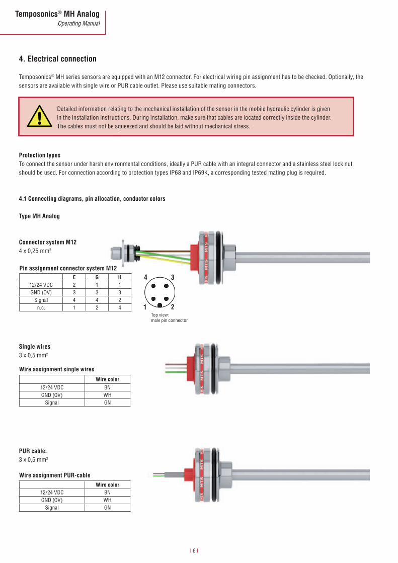
4. Electrical connection
Temposonics® MH series sensors are equipped with an M12 connector. For electrical wiring pin assignment has to be checked. Optionally, the sensors are available with single wire or PUR cable outlet. Please use suitable mating connectors.
Protection typesTo connect the sensor under harsh environmental conditions, ideally a PUR cable with an integral connector and a stainless steel lock nut should be used. For connection according to protection types IP68 and IP69K, a corresponding tested mating plug is required.
Detailed information relating to the mechanical installation of the sensor in the mobile hydraulic cylinder is given in the installation instructions. During installation, make sure that cables are located correctly inside the cylinder. The cables must not be squeezed and should be laid without mechanical stress.
I 6 I
Temposonics® MH AnalogOperating Manual
Top view: male pin connector
Pin assignment connector system M12
E G H12/24 VDC 2 1 1GND (OV) 3 3 3
Signal 4 4 2n.c. 1 2 4
Wire assignment single wires
Wire color12/24 VDC BNGND (OV) WH
Signal GNn.c. YE
Wire assignment PUR-cable
Wire color12/24 VDC BNGND (OV) WH
Signal GN
4 3
21
Type MS Analog
Connector system M124 x 0,25 mm2
Single wires3 x 0,25 mm2
PUR cable3 x 0,5 mm2
I 7 I
Temposonics® MH AnalogOperating Manual
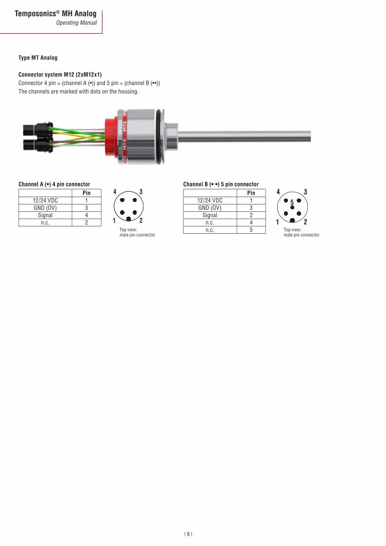
Top view: male pin connector
Channel A (•) 4 pin connectorPin
12/24 VDC 1GND (OV) 3
Signal 4n.c. 2
4 3
21
Channel B (• •) 5 pin connectorPin
12/24 VDC 1GND (OV) 3
Signal 2n.c. 4n.c. 5
4 3
21
5
Type MT Analog
Connector system M12 (2xM12x1)Connector4pin=(channelA(•))and5pin=(channelB(••))The channels are marked with dots on the housing.
I 8 I
Temposonics® MH AnalogOperating Manual
Top view: male pin connector
Top view: male pin connector
Protection against wrong polarity of VDC-GND is always ensured. Signal must always be connected to the controller input.
4.2 Order of connection
MH sensors with analog output (VDC/mA)
Correct connection
Please pay attention to connecting sequence!
Order Wire color Assignment
1 BN 12/24 VDC
2 WH GND (OV)
3 GN Signal
12/24 VDC
GNDSignal
12/24 VDC
GND
Signal
BAT
GND
IN
BAT
GND
INRL
RL
Polarity protection VDC-GND
VDC mA
RL > 10 kΩ @ 12/24 VDC RL < 250 Ω @ 12VDC
RL < 500 Ω @ 24 VDC
I 9 I
Temposonics® MH AnalogOperating Manual
4.3 Diagram for connection to the vehicle electronics
Machine groundTo ensure perfect operation of the sensor, the hydraulic cylinder must be connected to the machine ground. Equipotential bonding is often ensured by the mechanical contact between the cylinder and other machine elements. If the cylinder is connected with the machine sepa-rately, separate grounding, for example via a grounding strap directly on the cylinder must be ensured.
Cable shielding In the installed condition, the sensor is shielded sufficiently by the metal hydraulic cylinder. For this reason, no separate shielding is taken via the M12 connector. If a shielded cable is used, certain ap-plications may require checking, if both ends of the shielding must be connected to the machine ground. When checking, the effect of any high voltage and high frequency field in the vicinity on the shield and on the signals in the cable should be taken into account.
VDC (+12/24 V)GND (0V)Signal
Kabelschirm / Cable shield (option)
Cylinder an Chassis (GND)
Chassis GND
Diesel Motor / Diesel Engine
- Electrical power supply from battery (charged by generator)- Load dump protection and EMC requirements acc. to vehicle standards
ECU
+12 / 24 VDC
I 10 I
Temposonics
® MH Analog
Operating Manual
Signal GN
D and power supply G
ND (E.g. m
A-signal)
Shortcut Sensor ECU
Signal to Chassis (GND) J
+24 VDC to Chassis (GND) J L
GND to Chassis (GND) J
Within the ECU a protection from +24 VDC to Chassis GND must be installed.
+12 / 24 VDC GND (0V)Signal
2 cable shield
VDC (+) GND (-)Power supply RL= 500 Ω (24 VDC)
250 Ω (12 VDC)
1. Conductive metal Connector HousingCylinder to chassis earth- input filter of sensor become active
2. Cable shield connected to chassis GND on both sides: Protection against electro-magnetic interference
RL
Chassis GND
— IN
1
1
2
I 11 I
Temposonics
® MH Analog
Operating Manual
5. Operation and function5.1 Filter circuitry (noise)
Any resistor causes for example thermal noise, which is more or less evident at the output of the circuitry if amplified accordingly. Additionally, external effects such as the supply voltage ripple or electro-magnetic fields in the immediate vicinity can affect the noise spectrum.
To minimize noise, the use of a filter is mandatory with analog measurement. A suitable solution for noise suppression is the following filter with a limiting frequency of approx. 3 kHz. (noise reduction factor 3.6 - see figure below). The signal delay is within the cycle time and changes the dynamic behavior only insignificantly.
Sensor with analog output
Fig.: Filter at the controller input
Please pay attention: The resolution of the sensor output is influenced by the A/D converter of ECU input. e.g. 8 bit = 256 steps 10 bit = 1024 steps 12 bit = 4096 steps
Signal output characteristic during power up time:The sensor is ready to run after the power up time. Within the power up time the output signal is ,high‘: the indicated value is > F.S.O = Full Scale Output.
Inrush current / selection of suitable fuseTo select the correct fuse, please pay attention to the maximum current load and response time. The short time inrush current peak must be consid-ered when the sensor is in power on mode.
Please pay attention to actual valid data sheets and specifications!
At MTS, the sensor set points are calibrated with a tolerance of ± 1 mm. When installing in cylinders, please note that any additional tolerances must be taken into account. During teach-in, all tolerances in the cylinder-and-sensor system are eliminated. The piston rod drives towards the zero or full scale. The measured signals are programmed accordingly in the controller. During operation without teach-in, the following tolerances should be taken into account (values are applicable to magnet 401032):
Example: Measuring range 400 mm (Signal span 4000 mV)
Signal: 0.5 – 4.5 VSpan: 4000 mVSet point tolerance (SP): ± 1 mm = 10 mVMagnet tolerance (M): ± 1 mm (max.) Cylinder tolerance (Z): ± 1 mm
SP: : typ. zero or full scale tolerance M: max. tolerance of the magnet Z: adequate tolerance of the magnet
Electric signal with all tolerances:M + Z + SP = 3 mm
3 mm = 30 mV
5.2.1 Set point tolerance VDC, e.g. 400 mm
@ Zero: 0,5 V ± 30 mV For the zero, the permissible tolerance is: 0.5 V ± 30 mV@ Full scale: 4.5 V ± 30 mV For the full scale, the permissible tolerance is: 4.5 V ± 30 mV
5.2.2 Set point tolerance mA, e.g. 400 mm
@ Zero: 4 mA ± 0.12 mA For the zero, the permissible tolerance is: 4 mA ± 0.12 mA @ Full scale: 20 mA ± 0.12 mA For the full scale, the permissible tolerance is: 20 mA ± 0.12 mA
After installing the sensor in the cylinder, the deviations from the required signal valuesare within the defined tolerances. These deviations must be taken into account by the control systems, or when determining limit values.
Signal: 4...20 mASpan: 16 mA Set point tolerance: ± 1 mm = 0,04 mAMagnet tolerance: ± 1 mm (max.) Cylinder tolerance: ± 1 mm
Electric signal with all tolerances:M + Z + SP = 3 mm
3 mm = 0,12 mA
Min Max
Null 0.47 V 0.53 V
F.S. 4.47 V 4.53 V
I 13 I
Temposonics® MH AnalogOperating Manual
5.3 Insulation checks
Part of the testing performed on off-road mobile machinery can be insulation checks. During these checks, high voltages are applied to deter-mine the dielectric strength of the cables against the housing (insulation resistance). For testing, all connecting cables must be disconnected from the sensors. Otherwise, stray voltage flowing through the sensor protective circuitry against ground can cause damage or failure of these components and of the sensors.
5.4 Welding
After installing the cylinder in machines, welding work on adjacent components can be necessary. If a grounding tong is applied directly or too closely to the cylinder, welding currents can be transmitted to the sensor via the cylinder and cause burning of the sensor pipe or damage of internal sensor components. Cylinders mostly consist of two assemblies: the lower part with the cylinder pipe (Figure, shown in dark gray) and the piston with the piston rod (light gray). These components are isolated electrically from each other by gaskets, bearings and slide rails. This means that, normally, no current flow is pos-sible. With cylinders, however, the welding current may be transmitted from the piston to the cylinder pipe. In this case, an electrical connection causes the entire welding current to flow through the sensor pipe and the sensor head, thus damaging the electronics. Moreover, the cylinder and/or the gaskets are destroyed.
For this reason, the instructions given below must be followed: •Cutordisconnectallsensorconnectionsduringwelding.•Neverfastenthegroundingpointatthepistonrodoratthecylinderpipe.•Neverperformweldingworkonapartofthecylinder,ifasensorhasbeeninstalled.•Neverperformweldingworknearacylinder,ifasensorhasbeeninstalled.•Duetoisolatingbearings,plasticslidebearingsorgreaseinthecontactpoints,electricpotentials/voltagescanbuildupat
every bearing point of machines. Accordingly, similar effects as on hydraulic cylinders can be produced.
I 14 I
Temposonics® MH AnalogOperating Manual
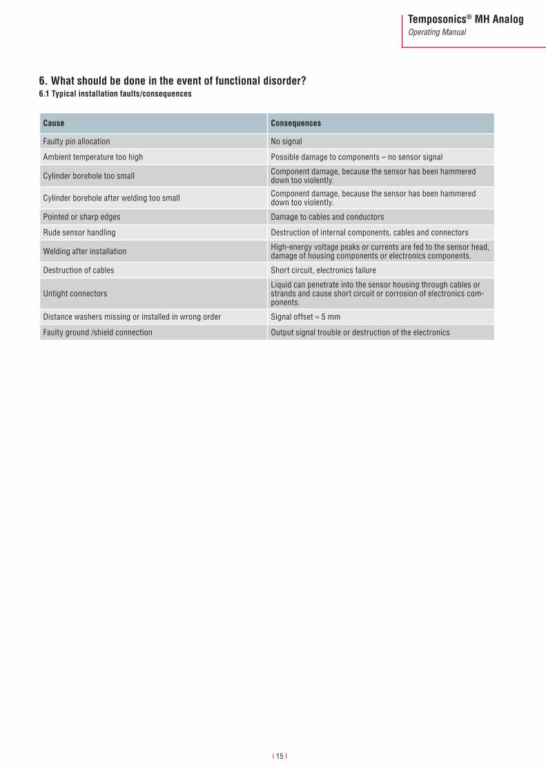
6. What should be done in the event of functional disorder? 6.1 Typical installation faults/consequences
Cause Consequences
Faulty pin allocation No signal
Ambient temperature too high Possible damage to components – no sensor signal
Cylinder borehole too small Component damage, because the sensor has been hammered down too violently.
Cylinder borehole after welding too small Component damage, because the sensor has been hammered down too violently.
Pointed or sharp edges Damage to cables and conductors
Rude sensor handling Destruction of internal components, cables and connectors
Welding after installation High-energy voltage peaks or currents are fed to the sensor head, damage of housing components or electronics components.
Destruction of cables Short circuit, electronics failure
Untight connectorsLiquid can penetrate into the sensor housing through cables or strands and cause short circuit or corrosion of electronics com-ponents.
Distance washers missing or installed in wrong order Signal offset ≈ 5 mm
Faulty ground /shield connection Output signal trouble or destruction of the electronics
I 15 I
Temposonics® MH AnalogOperating Manual
6.2 Checking the sensor function
Analog sensors (current or voltage output and PWM) •Checktheconnectionsandthepinallocation•Checkthesupplyvoltage•Disconnectthesensorandtestitinconnectionwithanexternal
power supply (e.g. car battery) •UseaTemposonics® test unit. The operating instructions of the test unit are
available for downloading from the log-in area under www.mtssensor.com •Usethemultimeterinaccordancewiththeexplanation.
Measuring the 4...20 mA output signalMeasure the 4...20 mA output signal using a multimeter and select the mA measuring range. Connect the multimeter with the green signal con-ductor and the white 0 V conductor. Connect the (+12/24 VDC) supply voltage to the brown conductor and O V (-0 V) to the white conductor.
Alternatively, the 4-20 mA output signal can be measured using a resistor (e.g. 100 Ω), which is connected with the green signal conductor and the white 0 V conductor. Now, select the VDC measuring range of the multimeter and connect the multimeter in parallel to the resistor.
Example: With a 100 Ω resistor, the following values are displayed.
Supply voltage at 4mA (Null Zone) at 20mA (End Position)
12 VDC, 24 VDC 0,4 V 2 V
Supply voltage12/24 VDC
Multimeter
Supply voltage12/24 VDC
Multimeter
Measuring using a multimeter (mA)
Measuring using a multimeter (VDC) and a resistor
I 16 I
Temposonics® MH AnalogOperating Manual
Measuring the VDC output signalUse a multimeter and select the VDC multimeter measuring range to measure the output signal (0.25 – 4.75 VDC; 0.5 – 4.5 VDC and 0.5 – 9.5 VDC). Connect the multimeter with the green signal conductor and the white 0 V conductor. Connect the supply voltage (+12/24 VDC) to the brown conductor and O V (-0 V) to the white conductor.
media. No license of any intellectual property rights is granted. The information is subject to change without notice and replaces all data sheets previously supplied. The availability of components on the market is sub-ject to considerable fluctuation and to accelerated technical progress. Therefore we reserve the right to alter
certain components of our products depending on their availability. In the event that product approbations or other circumstances related to your application do not allow a change in components, a continuous supply
with unaltered components must be agreed by specific contract.