+ All Categories
Home > Documents > Tender Document: C-2(b)/RC/0700/4399/2016 FORMAT NO. : … · 2016-08-30 · Annexure - A Tender...

Tender Document: C-2(b)/RC/0700/4399/2016 FORMAT NO. : … · 2016-08-30 · Annexure - A Tender...

Date post: 13-Apr-2020
Category:
Upload: others
View: 2 times
Download: 0 times
Share this document with a friend
44
Tender Document: C-2(b)/RC/0700/4399/2016 FORMAT NO. : CEL/FR/MMD/03(01) CENTRAL ELECTRONICS LIMITED (A Public Sect or Ent erprise) TENDER DOCUMENT for “Supply of BOS, Installation, Commissioning, Testing and Warranty for 5 Years of 2 X 50 KWp Grid Tied SPV Power Plant along with all necessary accessories including all required parts complete in all respect at Varanasi Railway StationTender Notice No. C-2(b)/RC/0700/4399/2016 dated 30 th August, 2016 Assistant General Manager (Materials) Materials Management Division Central Electronics Limited, 4, Industrial Area, Saur Urja Marg, Sahibabad – 201 010 (UP) INDIA Tel. No. 0091-120-2895145 Fax No. 0091-120-2895148 Email: [email protected] Website: www.celindia.co.in Page 1 of 44
Transcript

Tender Document: C-2(b)/RC/0700/4399/2016

FORMAT NO. : CEL/FR/MMD/03(01)

CENTRAL ELECTRONICS LIMITED

(A Public Sector Enterprise)

TENDER DOCUMENT

for

“Supply of BOS, Installation, Commissioning, Testing and Warranty for 5 Years of

2 X 50 KWp Grid Tied SPV Power Plant along with all necessary accessories including all required parts complete in all respect at Varanasi Railway Station”

Tender Notice No. C-2(b)/RC/0700/4399/2016 dated 30th

August, 2016

Assistant General Manager (Materials) Materials Management Division Central Electronics Limited, 4, Industrial Area, Saur Urja Marg, Sahibabad – 201 010 (UP) INDIA Tel. No. 0091-120-2895145 Fax No. 0091-120-2895148 Email: [email protected] Website: www.celindia.co.in

Page 1 of 44

Tender Document: C-2(b)/RC/0700/4399/2016

FORMAT NO. : CEL/FR/MMD/03(01) CENTRAL ELECTRONICS LIMITED

(A Public Sector Enterprise) 4, Industrial Area, Saur Urja Marg, Sahibabad – 201 010 (UP) INDIA

Tel. No. 0091-120-2895145 Fax No. 0091-120-2895148 Email: [email protected] Website: www.celindia.co.in

TENDER NOTICE

Tender Notice no. C-2(b)/RC/0700/4399/2016 30th

August, 2016

Central Electronics Limited invites sealed bids (Technical & Financial) from eligible bidders which are valid for a minimum period of three months from the date of opening for “Supply of BOS, Installation, Commissioning, Testing and Warranty for 5 Years of 2 X 50 KWp Grid Tied SPV Power Plant along with all necessary accessories including all required parts complete in all respect at Varanasi Railway Station”

Scope of Work “Supply of BOS, Installation, Commissioning, Testing and Warranty for 5 Years of 2 X 50 KWp Grid Tied SPV Power Plant along with all necessary accessories including all required parts complete in all respect at Varanasi Railway Station”

Earnest Money

Deposit

Rs.62,000/- (Rupees Sixty Two Thousand Only)

Interested parties may view and download the tender document containing the detailed terms &

conditions, free of cost from the website http://eprocure.gov.in/ or http://www.celindia.co.in

Please see document control Sheet at Annexure-1

For CENTRAL ELECTRONICS LIMITED

Sd-

Assistant General Manager (Materials)

Materials Management Division

Page 2 of 44

Tender Document: C-2(b)/RC/0700/4399/2016

Annexure-1

Important dates

Tender Reference No. C-2(b)/RC/0700/4399/2016 Name of Organization Central Electronics Limited

Tender Type

(Open/Limited/EOI/Auction/Single)

Limited

Tender Category (Services/Goods/works) Goods

Type/Form of Contract (Work/Supply/

Auction/Service/Buy/Empanelment/Sell)

Buy

Payment Mode (Online/Offline) Offline

Date of Issue/Publishing 30/08/2016(13:00 Hrs)

Document Download/Sale Start Date 30/08/2016 (13:00 Hrs)

Document Download/Sale End Date 09/09/2016(15:00 Hrs)

Bid submission Start Date 30/08/2016 (13:00 Hrs)

Last Date and Time for Submission of Bids 09/09/2016 (15:00 Hrs)

Date and Time of Opening of Bids 09/09/2016 (15:30 Hrs)

This is a limited tender and only the EPC contractors registered with CEL (except M/s. Nice International, Delhi/Sahibabad) are eligible to quote.

Page 3 of 44

Tender Document: C-2(b)/RC/0700/4399/2016

TENDER DOCUMENT for Tender notice No. C-2(b)/RC/0700/4399/2016

Important Instructions: - 1. The following documents/Annexures are part of tender document:

a. Tender notice b. Document Control Sheet Annexure -1 c. Price bid format (as given at) Annexure ‘A’ d. Detailed Specifications & Eligibility Criteria Annexure ‘B’ e. Commercial terms & conditions Annexure ‘C’ f. Format for submission of Vendor Data Annexure ‘D’ g. Tender acceptance letter Annexure ‘E’

2. Quotations shall be liable to be rejected if there is/are any deviation(s) from the specifications. 3. Escalation in price (except where price variation clause is applicable and given as per relevant clause of

tender), deviation from delivery schedule, terms and conditions will not be permitted in your quotation. Statutory Taxes & Duties should be shown separately from the price.

4. Bidder who is Micro & Small Enterprise should enclose copy of valid Certificate of Registration with DIC or KVIC or KVIB or Coir Board or NSIC or DHH or any other body specified by Ministry of Micro, Small and Medium Enterprises, Govt. of India to avail benefits under the “Public Procurement Policy for Micro & Small Enterprises (MSEs) Order 2012”, as per Eligibility Criteria.

5. Catalogue, literature, specification details should accompany the quotation. Incomplete quotations are liable to be rejected.

6. Any deviations whether technical or commercial stated anywhere in the bid shall not be taken into account and may render the bid non-responsible and liable to be rejected.

7. Vendor Data should be submitted in the Format for submission of Vendor Data as per annexure D. 8. Quotation should be submitted in Two bid system.

9. Tender/Quotation/Bid should be submitted in sealed covers super-scribing the tender notice no., name of the item and due date should be delivered at the Office of the Asstt. General Manager, Materials Management Division, Central Electronics Limited, 4, Industrial Area, Saur Urja Marg, Sahibabad – 201010 (U.P), INDIA. Last date of receiving of tenders/quotations is 14

th September 2016 up to 15:00

hrs IST. There will be two sealed covers/envelopes in the quotation. The following are to be submitted in your quotation signed and stamped on all pages: Cover-1

i. Demand Draft/RTGS details towards Earnest Money Deposit/copy of NSIC/DIC certificate ii. Filled up Format for Submission of Vendor Data as per format at Annexure D. iii. Drawings/data sheet/catalogue clearly showing that the offered material is meeting the

specifications given in the tender. iv. Tender acceptance letter as per format at Annexure E. v. Documents mentioned in the “Eligibility Criteria” given in Annexure-A

Cover-2

i This must contain only price bid as per the format given in Annexure-A

PLEASE DO NOT ATTACH THE TENDER DOCUMENT

SAVE PAPER

Page 4 of 44

Annexure - A

Tender for Supply of balance of system, Installation, commissioning, Testing and warranty for 5 years

of 2x50KWp Grid Tied SPV Power Plants along-with all the necessary accessories required as per

tender at following location including all the required parts, complete in all respect, F O R site”

LOCATIONS OF POWER PLANTS

S.N0. RAILWAY CAPACITY OF

SOLAR PLANT

IN KWp (2x50)

ADDRESS

1 Northern Railway 2 Sets of 50KWp Varanasi Railway Station

Eligibility Criteria

In order to be eligible to participate in the tender, the bidder must fulfill the following

eligibility criteria. Any discrepancy or departure from the same shall make the bidder

ineligible for participating in the tender:

1. The bidder must be approved EPC contractor for Solar product with CEL.

2. The bidder’s company/firm must have designed, manufactured, tested, and

commissioned cumulative 50KWp of Solar Power Plants for any government

department/PSU/NGO/ NSE Listed company/Regd. Co-operative society during last 3

financial years. One project of minimum 20KWp must be executed by the bidder during

last 3 financial years. The PO copies and completion documents are required to be

submitted with the bid.

3. The bidder must submit the Authorization from OEM’s for Inverter for this tender as

per the format.

Page 5 of 44

BILL OF QUANTITIES FOR SUPPLY OF BOS, INSTALLATION, COMMISSIONING AND WARRANTY FOR 5

YEARS OF 2X50KWp GRID TIED SPV POWER PLANTS

BOQ FOR 50KWp

*Note: Size and quantity of items may vary according to the actual site conditions. Any item, which is

not specifically mentioned but necessary for making the Solar Power Plant fully functional, shall

deemed to be included in the scope of work of the contract and shall be supplied and installed

by the successful bidder without any extra cost to the owner. For all other technical

specifications kindly refer Annexure B.

Sr. no. Description Quantity

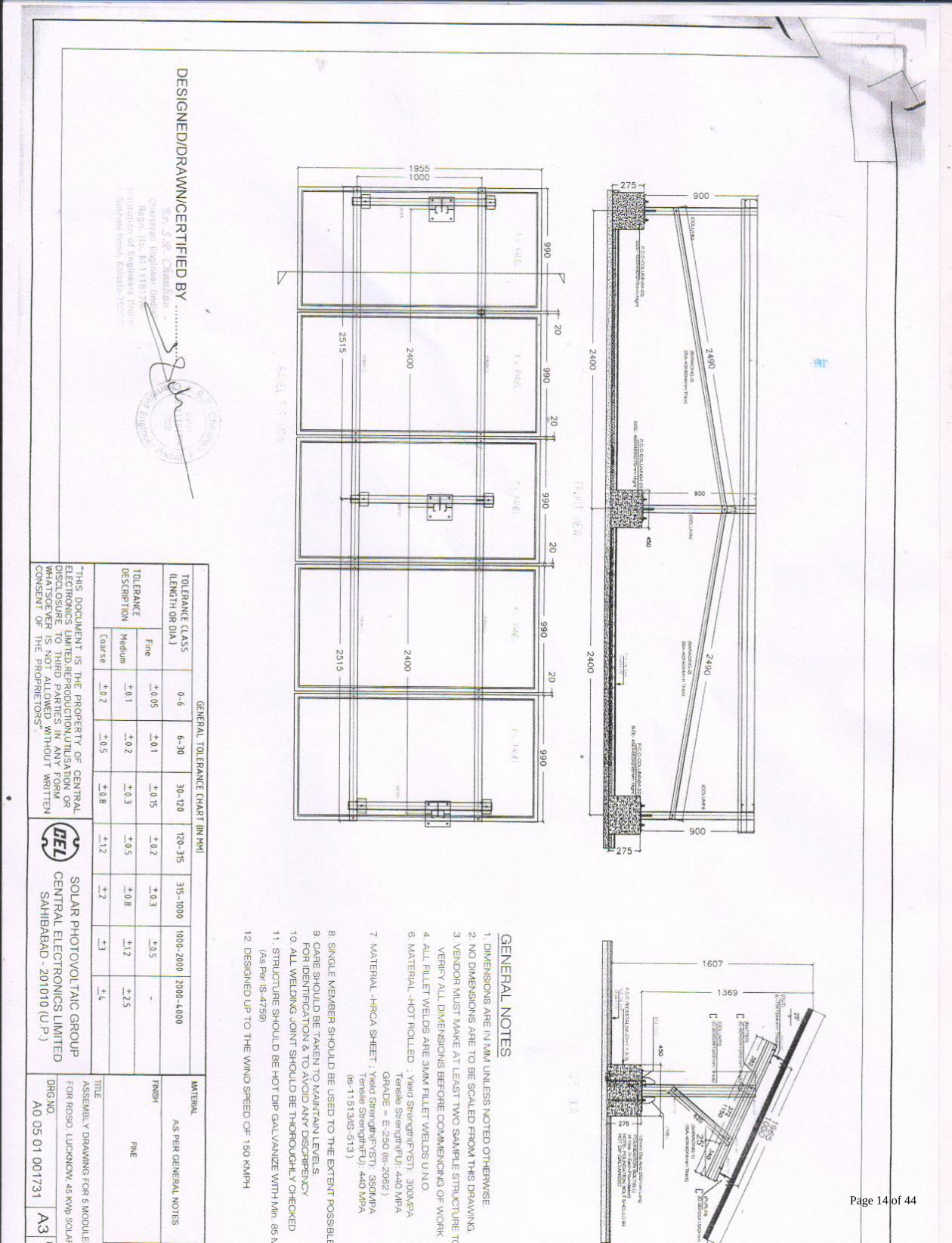
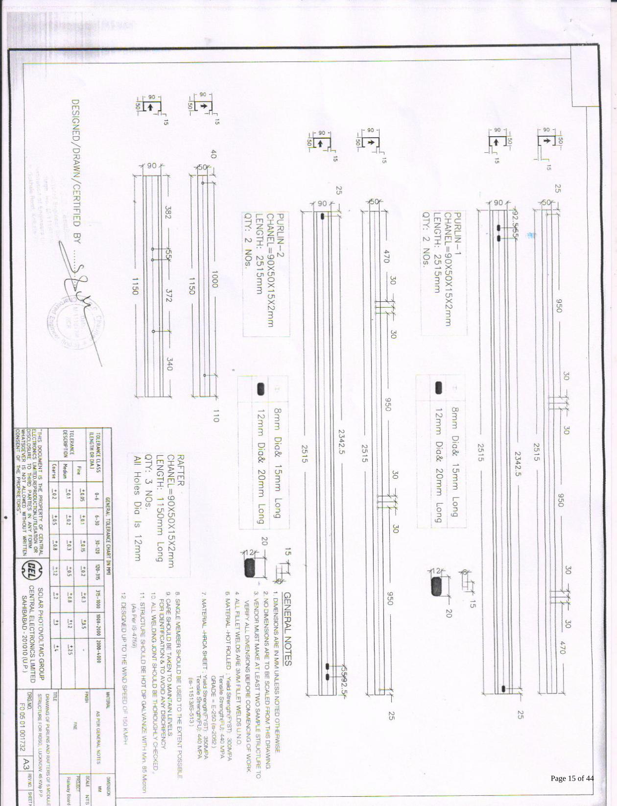
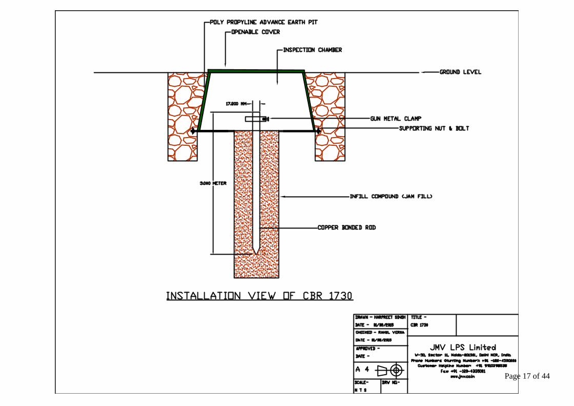
01. Supply of MS Galvanized Module Mounting Structures along with necessary

hardware as per drawing attached (Drg. No. A0 05 01 001731)

01set

02. Array Junction Box (DCDB) as per enclosed drawing with IP 65 protection.

(Make Hensel)

01 set

03. Supply of 2x25KVA or 1x50KVA Inverter with RS232/RS485 port and

LAN/WAN interface along-with accessories as per enclosed specifications

(Make- Fronius / Delta )

01 set

04. Supply of communication system, solar Insolation sensor, Array yard Temp.

sensor etc. with accessories along with termination (cabling etc.) upto

computer using suitable data cables i.e CAT 6 (Web-monitoring) – (Make-

Fronius/Delta)

01 set

05.* Supply of copper cable PVC insulated, Flexible multistrand, annealed copper

conductor un-armoured 1100V grade, conforming to relevant IEC of

following sizes as per technical specifications

• 1 X 6 mm2 for Interconnection & upto inverter

• 4 X 16/25 mm2 from Inverter to Bus Bar Box/LT Panel

• 1 X 10/16 mm2 for earthing inverter side (Green)

• 3.5 X 35/50 mm2 from Bus Bar Box/ACDB (LT Panel) and ACDB to Grid

Panel of customer (Al. Armoured)

(Make APAR Cables)

As required

06. Supply of Bus bar Box & ACDB (LT Panel) as per enclosed specifications with

all glands etc. (Make Hensel)

01 set

07. Supply and installation of earthing systems for complete array field, DCDB,

Bus Bar Box, ACDB, inverters and LT panel etc. as per relevant IS:3043-1987

including using suitable GI strip.

(Drawings for the earthing layout/location must be got approved from CEL

before start of work) ---Make JMV

01 job

08. Supply and installation of Lightning arrestor system as per relevant IEC -

62305 including separate earthing using suitable GI strip.

(Drawings for the Lightning arrestors alongwith earthing layout/location

must be got approved from CEL before start of work)---Make JMV

01 job

09. Supply & Installation of Bird Spikes on each Modules as per CEL’s Instruction 01 Job

10. Other Misc. work like cleaning, Plastering painting, white wash etc. related

to installation and commissioning of Power Plant. Testing & Commissioning

of system of the whole system prior to hand over of the system.

01 job

Page 6 of 44

Job Works

1. Construction of pedestals (PCC/RCC 1:2:4 as per site) for each of the module mounting

structures as well as fixing of the above structure at the roof top or at ground including supply

of civil foundation materials.

a. The installation of SPV modules should not impact the waterproofing of the existing

terrace structure. The contractor shall be responsible for restoring the waterproofing

to its original condition and for provision of additional waterproofing in the areas

where RCC blocks are secured onto the terrace.

2. Mounting & fixing of 50KWp of SPV Module (supplied by CEL at site upto store) on the above

installed structure. (The entire fixed module should be aligned systematically)

3. Mounting of all the junction boxes with suitable arrangement as required for the power plant.

4. Interconnection of modules in series-parallel combinations as per following:

a) Each source-circuit to have suitable number of modules in series using 1x6 mm2 wires

(Interconnects supplied with modules and cables interconnection is to be carried out using

UV conduit pipe/cable trays)

b) Output of series connected modules to be taken to PJB’s/DCDB using 1 X 6 mm2 wires.

(Cables interconnection is to be carried out using UV conduit pipe/cable trays)

c) Output of PJB/DCDB to be taken to corresponding Inverter using 2 X 6 mm2 wires. (Cables

interconnection is to be carried out using UV conduit pipe/cable trays)

d) Output of inverters are to be taken to Bus Bar Box/ACDB using 4 X 16 mm2 wires and

1x10/16 mm2 for earthing. (Cables interconnection is to be carried out using UV conduit

pipe/cable trays)

e) Output from ACDB to be connected to LT Panel of building using 3.5 x 35/50 mm² cables. All

the cables interconnection is to be carried out using cable tray.

5. Installation and commissioning of 2x25KVA or 50KVA inverter with suitable cable tray etc.

along-with the cabling for data communication in throughout the Power Plant up to customer’s

computers using suitable data cables.

6. Installation of earthing and lightning arrestor system as per relevant IS:3043-1987 & IEC-62305

for the entire PV array field & Inverter etc..

7. Other Misc. work like Plastering, cleaning, painting, white wash etc. related to

installation and commissioning of Power Plant. Testing & commissioning of system of the

whole system prior to hand over of the system.

SCOPE OF WORK:-

a) Bidders are advised to conduct site survey before submitting their bids.

b) Bidder must start the work at site within 15 days from the date of issue of purchase order.

c) Contractor has to prepare all required site drawings and the same are to be got approved from

concerned Railway authority & CEL officials. Page 7 of 44

d) To arrange for pre-dispatch inspection by CEL officials.

e) To deliver the materials at site.

f) Contractor shall make his own arrangement for safe storage of their as well as CEL material

(Which will be supplied to him by CEL) at site.

g) To co-ordinate with CEL/Railway officials for verification of completed works along-with all the

required documentation and collection of payments from Railways.

h) Materials, wherever supplied, shall be provided with fresh quality. Workmanship shall be neat

& clean without any blemish. In case of any observation by CEL official regarding materials &

workmanship, the same have to replaced and/or repaired to the satisfaction of CEL/Railway

official.

i) No extra transportation charges shall be paid during the period of contract.

j) No escalation shall be applicable on the above prices.

k) In case of any losses, theft or damage of material, the contractor shall alone be responsible to

make alternate arrangement for completion of the project within contractual delivery,

commissioning and handing over to Railways within quoted price. The purchaser shall in no

way, whatsoever, responsible to compensate the contractor in this account.

l) Contractor shall arrange all the utilities required to complete the work. No payment on this

account shall be paid by CEL.

m) Inspection:- All the materials shall be inspected by CEL officials before despatch to site.

n) Any other work as required on the site for completion of the project.

o) The contractor/bidder shall not display the photographs & content of the work and

also will not take advantage through publicity of the work without written

permission of CEL. Noncompliance to this may result in removal from the EPC list and

the contractor will be blacklisted.

p) Service level agreement has to be signed on 100/- stamp paper after award of PO.

p) Weekly progress report:

The contractor shall furnish on first day of every week, a progress showing progress of

finalization of designs and drawings, materials received at site and the works carried out

during the preceding weeks and plan for the next week. As far as possible the presentation

shall be neat and tabulation form accompanied by coloured diagram wherever applicable.

Besides this bidder has to submit monthly progress report.

q) O&M Manual/Maintenance Manual:

The supplier shall provide easy-to-use illustrated installation and operation manual ( 4

c o p i e s ) in English and local language for easy installation and trouble-free usage.

Manual shall contain complete system details such as array layout, schematic of the

system, working principle, clear instructions on regular maintenance, trouble shooting of the

system and emergency shutdown procedures.

r) During Warranty of 5 years contractor has to perform the following duties:

1. Contractor is fully responsible for the trouble free maintenance and is liable to rectify /

remove any defect noticed within the aforesaid period free of cost for the materials

supplied by them.

Page 8 of 44

2. The Contractor and CEL jointly impart training to the user’s on day to day repair and

maintenance of the systems.

3. This includes repair/ replacement of all spares and consumable supplied by Contractor

during the Warranty period.

4. The Contractor shall undertake the periodical maintenance work of complete Solar Power

plant (which includes cleaning of Modules & all equipment) on the 10th of every succeeding

quarter duly countersigned by the concerned officials of beneficiary.

5. The Contractor should be in readiness to attend to the defects of any system, as and when

required by the beneficiary and ensure rectification of defects and restore functionality

within seven days of lodging the complaints. The Contractor shall furnish the status report

after the maintenance work are over, which shall invariably bear the signature of the

beneficiaries.

6. It will be the liberties of the CEL to cross check the systems maintained by the contractor.

Random verification of the maintenance may be carried out by the CEL party wherever

necessary.

s). Payment Terms: - Payment shall be made back to back as per the following terms on pro-

rata basis:

1. 100% payment towards supply & 100% of I/C after installation &

commissioning of system excluding AMC after submission of

Acceptance & routine test report by RDSO/Concerned Railway

department and PBG of 10% of total order value valid till the warranty

period.

2. Payment towards AMC shall be released after every six month basis on

submission of quarterly reports duly signed by concerned Railway

officials.

t). Completion Time: The entire job has to be completed within 2 months after release of PO.

u) Liquidated Damages: In the event of delay in affecting the delivery within agreed period, a

reduction in the price shall be levied @ 0.5% of the total order value per

week or part thereof subject to maximum of 10% of the total order

value.

v) Security Deposit: 2% of order value as security in must be submitted with acceptance of

the purchase order in the form BG/DD/FDR valid till completion of the

project.

Page 9 of 44

SUPPLY, INSTALLATION AND COMMISSIONING OF BOS FOR 2x50 KWp

SPV POWER PLANTS

PRICE BID

S.No.

Description Amount (Rs.)

2x50KWp

1.

Supply of Materials

2.

Tax on supply

3.

Installation & commissioning

Charges

4.

Service tax on I/C

5. Total Price (A)

6. AMC Charges for 5 years

(*Minimum 1.5% per annum of A

above)

7. Service tax on AMC

Total for each system

Quantity 19 sets

G. Total for supply, installation,

commissioning including 5 years warranty

In Words

*Note: If AMC offer is less than 1.5% than it shall be taken as 1.5% of A and offer will be evaluated accordingly.

(Signature of authorized representative)

Page 10 of 44

MANUFACTURERS' AUTHORIZATION FORM

Ref. No. dated________

To

M/s. Central Electronics Limited

4, Industrial Area

Sahibabad-201010 (UP)

Tender No.:

Dear Sir:

We who are established and reputable manufacturers of

________________________ (name & descriptions of goods offered) having factories at

(address of factory) do hereby authorize M/s ____________________________ (Name and

address of Agent) to submit a bid, and sign the contract with you for the goods manufactured

by us against the above tender.

We hereby extend our full guarantee and warranty as per the General Conditions of

Contract for the goods and services offered for supply by the above firm against this tender.

Yours faithfully,

(Name)

(Name of manufacturers)

Note: This letter of authority should be on the letterhead of the manufacturer and should be

signed by a person competent to legally bind the manufacturer. It should be included by

the Bidder in its bid.

(The list of items for which this is required should be indicated by Purchaser).

Page 11 of 44

SL DESCRIPTION QNT. UNIT MAKE

1 SUPPLY OF MS GALVANIZED MODULE MOUNTING STRUCTURE

ALONG WITH NECESSARY HARDWARE OF AS PER SITE CONDITIONS

1 SET Design as approved

by CEL

2 ARRAY JUNCTION BOX (DCCB) AS PER ENCLOSED DRAWING WITH IP

65 PROTECTION. HENSEL MAKE

1 Set HENSEL

3 SUPPLY OF 2x25KVA or 1x 50KVA INVERTER WITH RS-485 AND

ACCESSORIES

1 SET FRONIUS/DELTA

4 SUPPLY OF COMMUNICATION SYSTEM WITH ACCESSORIES ALONG

WITH TERMINATION (CABLING ETC.) UPTO CUSTOMER'S COMPUTERS

USING SUITABLE DATA CABLES i.e CAT 6

1 SYS FRONIUS/DELTA

4a Sensor Manager with IP 65 Box 1 SYS FRONIUS/DELTA

4b Irradiance & Module Temperature Sensor 1 SYS FRONIUS/DELTA

5 SUPPLY OF COPPER CABLE PVC INSULATED, FLEXIBLE MULTISTRAND,

ANNEALED COPPER CONDUCTOR UN-ARMOURED 1100V GRADE,

CONFORMING TO RELEVANT IS AND DULY ISI MARK OF FOLLOWING

SIZED SUITABLE FOR 0' TO 50' C TEMPERATURE

_ _ _

5a 1X6 MM FOR INTERCONNECTION-DC SOLAR As required MTR APAR

5b 1X10/16 MM FOR INTERCONNECTION (GREEN)- For Earthing As required MTR APAR

5c 1X6 MM FROM AJB TO INVERTER-DC SOLAR As required MTR APAR

5d 4X16/25 MM FROM INVERTER TO LT PANEL As required MTR APAR

5e 3.5X35/50 MM FROM BUS BAR BOX TO LT PANEL TO GRID PANEL (AL.

ARMOURED)

As required MTR APAR

6 SUPPLY OF BUS BAR BOX (AC Inv. Collector Panel) AS PER ENCLOSED

DRAWINGS & SPECIFICATIONS WITH ALL GRANDS ETC.

1 SET HENSEL

6a SUPPLY OF LT PANEL (ACDB) AS PER ENCLOSED DRAWINGS &

SPECIFICATIONS WITH ALL GRANDS ETC.

1 SET HENSEL

7 SUPPLY AND INSTALLATION OF EARTHING SYSTEM FOR COMPLETE

ARRAY FIELD AND INVERTERS, LT PANEL ETC. AS PER RELEVANT

IS:3043-1987 INCLUDING USING MIN 25X3MM GI STRIP.

5 SET (Min.) JMV

8 SUPPLY AND INSTALLATION OF LIGHTNING ARRESTOR SYSTEM 6 SET (Min.) JMV

9 SUPPLY AND INSTALLATION OF EARTHING SYSTEM FOR LIGHTNING

ARRESTOR INCLUDING USING MIN 25X3MM GI STRIP.

3 SET (Min.) JMV

10 Supply & Installation of Bird Spikes on each Modules as per CEL’s

Instruction

1 Job

11 OTHER MISCELLENEOUS WORK LIKE CLEANING, PLASTERING

PAINTING, WHITE WASH ETC. RELATED TO INSTALLATION AND

COMMISSIONING OF POWER PLANT. TESTING & COMMISSIONING OF

SYSTEM OF THE WHOLE SYSTEM PRIOR TO HAND OVER OF THE

1 Job _

CENTRAL ELECTRONICS LIMITED, SAHIBABAD

BILL OF MATERIALS

50KWp GRID TIED SPV POWER PLANTS

Note: The firm has to supply all the materials as per the BOM . Size and quantity of items may vary according to the actual site

conditions.Any item, which is not specifically mentioned but necessary for making the Solar Power Plant fully functional, shall be

deemed to be included in the scope of work of the contract and shall be supplied and installed by the successful bidder without any

extra cost to the owner. Page 12 of 44

Page 13 of 44

Page 14 of 44

Page 15 of 44

Page 16 of 44

Page 17 of 44

Page 18 of 44

Page 19 of 44

Page 20 of 44

Page 21 of 44

Page 22 of 44

Page 23 of 44

Page 24 of 44

Annexure - B

SPECIFICATION FOR GRID CONNECT SOLAR GENERATING SYSTEM

1.0 SCOPE:

This specification provides the generic requirement for grid connect solar

photovoltaic (SPV) system, after duly considering the MNRE norms for installation

of SPV Power system.

The specification covers general and technical requirements for design,

manufacturing, testing, supply, installation and commissioning of Grid connect solar

generating system to be provided at railway premises for meeting the railway

requirements of lighting, ventilation and other electrical services. The solar

photovoltaic generating system’s inverter will operate in parallel with the general

electric supply system on railway premises.

2.0 REFERENCE STANDARDS:

IS: 12834:1989

(reaffirmed 2000)

Solar Photovoltaic Energy Systems –

Terminology

IEC : 61215 Ed 2 or

Latest

Crystalline silicon terrestrial photovoltaic (PV) modules –

Design qualification and type approval

IEC: 61730 Pt 1 & 2 Photovoltaic (PV) module safety qualification

-Part 1: Requirements for construction Part 2:

Requirements for testing

IEC: 61701 Salt mist corrosion testing of photovoltaic (PV) modules

IEC:60904-1(2006) Photovoltaic Devices- Part-I: Measurement of Photovoltaic

current-Voltage Characteristic

IS: 9000 Basic environmental testing procedure for Electronic and

electrical items.

IEC:60068 Environmental testing

IEC 61723 Ed1.0 Safety Guidelines for grid connected photovoltaic systems

mounted on the buildings

IEC 60364-7-712

(2002)

Electrical Installations of Buildings Part 7: requirements for

special installations or locations

Section, 712: Photovoltaic power supply systems.

IEC 62446 (2009) Grid connected photovoltaic systems- Minimum

requirements for system documentation, commissioning

tests and inspection

Note: Normally latest version of the standards shall be referred to.

Page 25 of 44

4.0 SYSTEM DESCRIPTION:

4.1 Solar Photovoltaic (SPV) grid connect system shall consist of mainly the following: -

i) Solar Modules --- to be provided by CEL

ii) Module mounting structure

iii) Junction boxes

iv) Power conditioning unit (PCU)

v) Import & Export metering

vi) Cable and other accessories

4.2 The PV array converts the light energy of the sun to DC power. The module

mounting structure shall be used to hold the module in position. The DC power

shall be converted to AC by PCU to supply AC loads such as computers, lights, fans,

etc. within the railway premises. Solar power shall be integrated with the premises

power supply from electricity authority.

4.3 DC distribution board/ combiner shall be provided in between solar array and

PCU. It shall have DC Disconnector/MCCB of suitable rating for connection and

disconnection of array section. Type II Surge Arrestor should be incorporated for

surge protection. It shall have meters for measuring the array voltage and array

current. Appropriate IP protection shall be provided. In case of string inverters, if the

requirements served by DC distribution board are fully taken care of by string

inverter(s), then firms’ proposal (if any) for elimination of DC distribution board

from the system design, can be considered.

4.4 AC distribution board shall be provided in between PCU and loads. It shall have an

integrated energy meter, voltmeter and ammeter. As for energy, generally the parameter

of interest shall be the aggregate energy output of inverter(s) fed into the individual AC

distribution board(s). Though not mandatory, firms are however encouraged to also

offer the facility for recording the energy output data of each inverter (wherever multiple

inverters are feeding into an AC distribution board). Class I + II (as per IEC 62305) 100

kA Surge Arrestor should be incorporated for protection against surges.

4.5 ……….

4.6 The system shall comply IEC 60364-7-712 and 62446.

5.0 GENERAL REQUIREMENTS:

5.1 ……

5.2 Solar panels and array junction boxes shall be installed on shade free roof. In

case of string inverters, railways should carefully weigh the option of indoor vs.

outdoor installation. The installation of SPV modules on roof-tops must not

impact the waterproofing of the existing terrace structure. The contractor shall be

responsible for restoring the waterproofing to its original condition and for provision

of additional waterproofing in the areas where RCC blocks are secured on to the

terrace. Even though roof-top mounting of solar panels shall be the preferred option,

if necessary, railways can at their option specify a ground mounted solar system

for part or full system KWp capacity.

Page 26 of 44

5.6 Array structure of PV yard and all electrical equipments such as PCU, inverters,

etc. shall be grounded properly. Towards this end, the contractor will supply and

install an adequate number and appropriate size of IS:3043 – 1987 compliant

earthing kits for AC circuit, DC circuit and lighting protection system.

5.7 Suitable marking shall be provided on the bus for easy identification.

5.9 The reverse current of blocking diodes (connected in series), if required/

provided, shall be rated for 2 X VOC STC of the PV string.

5.10 Proper sealing arrangements at the points of cables entering the enclosures/

buildings should be incorporated. Although not mandatory,

Contractors are however encouraged that the cables entering into the enclosures

be sealed with modular EPDM based cable sealing and protection system based

on multi-diameter technology.

6.0 TECHNICAL REQUIREMENTS:

6.1 The DC output from the modules shall be fed to array junction box and the

strings are paralleled at sub Main & Main junction boxes. Then PCU shall

convert DC energy produced by the solar array to AC energy. The AC power

output of the inverter shall be fed to the AC distribution board (metering panel &

isolation panel), which also houses the energy meter. The AC output of grid-

connect SPV system should be paralleled with railway’s general electric power

supply i.e.the power supply received from the electricity authority.

6.2 The system shall automatically wake-up in the morning and supply power,

provided there is sufficient solar energy and the grid voltage and frequency are in

range.

6.3 When the grid voltage and/or frequency go out of preset range, the inverter shall

be immediately disconnected from the grid. The inverter will reconnect after a pre-

determined time when the grid is back in the range.

6.4 Array to inverter voltage drop shall be less than 3% at the maximum power

output of the array.

6.5 Railways shall provide adequate space and ventilation for the inverter. If string

inverters are used, the same can be installed below the solar array.

6.7 The performance and generation data shall be recorded using a data

logger. The monitoring system shall comprise of the following main components:

6.7.1 PCU will log the inverter performance data and transmit the same to the data

logger. It shall also monitor basic parameters like power generated, etc.

6.7.2 Data logger shall gather information and monitor the performance of the

inverter. It shall also support measurements from the external sensors. Data

Logger shall also monitor the Solar Insolation and Temp of Array Yard. RDSO and

the concerned railway shall be afforded free of cost facility for viewing the

system performance data on the manufacturer’s or system integrator’s or

railway’s web portal.

Page 27 of 44

6.7.3 Data logging system/software shall enable automatic long-term storage of

measured data from PV plant. It shall allow visualization, monitoring,

commissioning and service of the installation. The data logger shall be web

enabled. It should be possible to access the data logger with any standard web

browser like internet explorer, google chrome, etc. and for this purpose, relevant

software/ hardware will be supplied by the contractor. In addition to the web

portal, it should also be possible to retrieve the data directly from the data logger.

The software for access/ visualization of data from data logger should also be

provided by the supplier. Necessary executable files, if any, will be required to be

given free of cost by the supplier on a CD/ any other storage device.

6.7.4 Communication interface

The system should offer RS232/RS485 port and LAN/ WAN interface to facilitate

remote monitoring of the system.

6.10 Module Mounting Structure

6.10.1 The array structure shall be so designed that it will occupy minimum

space without sacrificing the output from SPV panels.

6.10.2 The structure shall be designed to allow easy replacement of any

module by authorized personnel and shall be in line with the site

requirements. Bird spike shall be provided so as to avoid bird sitting on the

solar modules at the highest point of the array/module structure.

6.10.3 The array structure shall be made of hot dipped galvanized MS angles (or

alternate MS sections) of suitable size. Galvanization thickness shall be of min.

85μm. If the systems are installed in coastal/ corrosive areas, the minimum

galvanization thickness of array structure shall be 120μm. Unless the purchaser

has specifically asked for 120 μm thickness, normally 85 μm will be supplied.

6.10.4 The foundation for module mounting structure shall be preferably 1:2:4

RCC construction or any other combination based on the local site condition

requirement for which design details shall be submitted.

6.10.5 The support structure, design and foundation shall normally be designed to

withstand wind speed upto 150 kmph.

6.10.6 The clearance between lowest part of the module structure and the

developed ground level shall normally not be less than 500mm. However, in

exceptional cases, lower clearances may be allowed on case to case basis.

6.10.7 The module alignment and tilt angle shall be calculated to provide the

maximum annual energy output. This shall be decided based on the location of

array installation. The SPV panel shall have a provision for angular adjustment

of the mounting structure to get maximum utilization of incident sunlight. It shall

be mounted facing south and tilted to an angle equal to the latitude (where being

used), for optimum performance.

6.10.8 Fasteners shall be of stainless steel SS304. To prevent pilferage, anti-theft

fasteners shall be provided at appropriate locations.

6.10.9 Junction Boxes

Array sub-main and main junction boxes, shall have the following properties:

a. They shall be dust, vermin & waterproof and made of Polycarbonate-

Page 28 of 44

Glass Fibre Substance (PC-GFS) thermoplastic. The enclosure should be double

insulated with protection class II as per IEC 61439-1. Material and the

protection class shall be marked on the enclosure.

b. The enclosure shall have a transparent front lid for enabling easy visibility.

c. The enclosures shall have IP 65/66 protection in accordance with IEC 60529.

Third party conformance certificate is required to be given for IP 65/ IP 66

degree of protection.

d. Minimum requirements for fire protection in the event of internal faults: Glow

wire test in accordance with IEC 60 695- 2-11 at 960C for box and 850C for

conducting components.

e. Burning Behavior: Base part of Polycarbonate Enclosure shall be UL94-V-0

compliant and Lid part of PC Enclosure shall be UL94-V-2 compliant.

f. The enclosures shall have IK 08 degree of protection for mechanical load.

g. The material used shall be halogen, silicon free conforming to RoHS directive

2002/95/EC.

h. The enclosure shall have a usage temperature rating of -10C to 55C.

i. The enclosure should be chemically resistant to acid, lye, petrol, mineral oil &

partially resistant to benzene.

j. The enclosures shall have a rated insulated voltage of 1000V DC and

dielectric strength of 4.65 KV DC.

k. The material of the enclosure shall be UV stabilized.

l. Though not mandatory, manufacturers are encouraged to provide breather

glands in the array junction boxes to prevent overheating and explosions.

ii) SPDs Class II as per IEC 61643-1, shall be used at the terminals of array

junction boxes for external surge protection. Internal Surge protection (SPDs)

shall consist of three MOV type arrestors connected from + ve and – ve

terminal to earth (Via Y arrangement) for higher withstand of the continuous

PV-DC voltage during earth fault condition. SPD shall have safe disconnection

& short circuit interruption arrangement through integrated DC in-built

bypass fuse (parallel) which should get tripped during failure mode of MOV,

extinguishing DC arc safely (created by inbuilt thermal disconnection) in order

to protect the installation against fire hazards. Nominal discharge current (In)

at 8/ 20 microseconds shall be minimum 10 KA with maximum discharge

current (Imax) of minimum 20 KA at 8/20 microseconds with visual indication

(through mechanical flag) in all modules to monitor the life of SPD. The Isc

wpv (Short Circuit current withstand capacity of arrester) would be at least 10%

more than Nominal output current of the combiner box and AJB. Detailed

internal schematic for the above SPDs, compliant to these specifications,

should be submitted by the contractor.

iii) The junction boxes shall have suitable cable entry points with cable glands

of appropriate sizes for both incoming and outgoing cables. Though not

mandatory, manufacturers are encouraged to provide suitable cable entry

points fitted with MC-4 Connectors.

iv) Suitable markings should be provided on the bus bar for easy identification,

and cable ferrules shall be fitted at the cable termination points for

identification.

v) The Array Junction Box should preferably have maximum 08 input with SPD

and Terminal block.

Page 29 of 44

6.10.10 Earthing for PV array, Balance of System (BOS), lightning protection and other

components.

i. The photovoltaic modules, Balance of system (BOS) and other components of

power plant require proper grounding for protection against any serious

faults as guided by IEC 60364.

ii. The earthing resistance must not exceed the limits generally in practice for

such applications.

iii. The Bidder shall submit the detailed scheme of earthing and grounding.

iv. The contractor will supply and install an adequate number and appropriate size

of IS:3043 – 1987 compliant earthing kits for AC circuit, DC circuit and lighting

protection system.

v. The source of over voltage can be lightning or other atmospheric

disturbance. Main aim of over voltage protection is to reduce the

overvoltage to a tolerable level before it reaches the PV or other sub-system

components. Lightning protection should be provided as per IEC 62305.

vi. Necessary concrete foundation or any other arrangement for holding the

lightning conductor in position is to be made after giving due consideration to

shadow on PV array, maximum wind speed and maintenance requirement at site

in future.

vii. The lightning conductor and structures shall be earthed through flats as per

applicable Indian Standards with earth pits. Each lightning conductor shall be

fitted with individual earth pit as per required Standards including accessories,

and providing masonry enclosure. Else, a matrix of lightning conductors is

to be created which will be required to be connected to an earth.

viii. If necessary, more numbers of lightning conductors may be provided.

ix. The Bidder shall submit the drawings and detailed specifications of the PV

array lightning protection equipment.

6.12 Power Conditioning Unit (PCU)

PCU shall supply the DC energy produced by array to DC bus for inverting to AC

voltage using its MPPT (Maximum Power Point Tracking) control to extract

maximum energy from solar array and produce 415V (+15% and -20%) AC, 3

phase, 50 ± 5% Hz (47.5 to 52.5 Hz) to synchronize with the local grid. For

sizing of grid connect inverter, the general guideline will be that the ratio of

SPV KWp rating to inverter’s KVA rating shall be within 1.15. The array output

should be well within the input voltage range of the inverter so that the

inverter works in MPPT range for most of the solar Insolation range. This should

be applicable for the whole life of the solar array and needs to be

substantiated through design calculations. PCU should be able to handle

maximum open circuit DC voltage of 1,000V.

6.12.1 MPPT controller, inverter and associated control and protection

devices, etc. all shall be integrated into the PCU.

6.12.2 PCU/ string inverter shall provide 3 phase, 415V (with grid tracking of

+15%/-20%), 50 Hz (with grid tracking of ±5% i.e. 47.5 to 52.5 Hz) supply on AC

side with voltage THD of less than 3% and current THD of less than 5%.

6.12.4 For transformer-less design, eff iciency shall be minimum 96%.

Page 30 of 44

6.12.5 Degree of protection will be minimum IP20 for non-electronics portion

where transformer, etc. are mounted, if any and for the rest of the portion

including electronics, it will be IP31 for units of capacities upto 15KWp and

IP41 for units of capacities greater than 15KWp. For inverters to be installed

outdoors, IP65 protection shall be required. In future, RDSO will actively

consider upgrading the requirement of IP protection, keeping in view the

highly dusty environment in Indian subcontinent. Therefore, manufacturers

are encouraged to develop even higher IP protected systems for future

requirements of IR.

6.12.6 Railways should carefully weigh the option of indoor vs. outdoor location

for string inverter.

6.12.7 The inverter shall be efficient with IGBT based reliable design. The

control system should be of highest reliability preferably based on Digital

Signal Processors.Though not mandatory, the manufacturers are encouraged

to provide the control system of redundant type.

6.12.8 The PCU shall be capable of complete automatic operation, including

wake-up, synchronization and shut down.

6.12.9 PCU shall have the facility to display the basic parameters of the system

on a typical 4 line by 20 characters type LED/LCD display. Displays of a

bigger size can also be provided.

6.12.10 PCU shall be able to synchronize independently and automatically/

phase-lock with POWER SUPPLY AUTHORITY grid power line frequency to

attain synchronization.

6.12.11 Built-in data logging to monitor plant performance through external

PC shall be provided.

6.12.12 Inverter shall be tested for islanding protection performance. 6.12.13

Only isolated inverters shall be grounded on DC side.

6.12.15 Indications (through LEDs/ LCD display)

Following is an indicative list of indications:

i) Inverter ON

ii) Grid ON

iii) Inverter under voltage/over voltage

iv) Inverter over-load

v) Inverter over-temperature

vi) Earth Fault

6.12.16 Protections

Following is an indicative list of protections:

i) Over-voltage both at input and output

ii) Over-current both at input and output

iii) Over/under grid frequency

iv) Over temperature

Page 31 of 44

v) Short circuit on AC side

vi) Reverse polarity protection

vii) Array ground fault protection

viii) Protection against lightning induced surges Class II, 10 kA as per

IEC 61643-1

ix) Protection against surge voltage induced at output due to external

source

6.12.17 Night consumption of the PCU shall be less than 0.2% of the rated

power of the inverter for system capacities of 25KWp or more. It shall be less

than or equal to 50W for system capacities of less than 25KWp.

6.1.2.18 Noise level of the PCU should be less than 65 dBA(nom.) at 1m.

6.12.19 DC insulation resistance should be more than 50MΩ.

6.12.20 EMI and EMC Requirements:PCU shall comply the following EMI and

EMC requirements:

i) Emitted interference as per IEC: 61000-6-4.

ii) Interference emitted as per IEC: 61000-6-2.

6.12.21 An integrated earth fault detection device is provided to detect eventual

earth fault on DC side and shall send message to the supervisory system.

6.12.22 Idling current at no load shall not exceed 2% of the full load current.

6.12.23 PCU shall withstand high voltage test of 2,000 Vrms between either

the input or the output terminals and the cabinet (chassis).

6.12.24 PCU includes ground lugs for equipment and PV array groundings.

The DC circuit ground shall be a solid single point ground connection.

6.12.25 Where PCU hasnot been provided with galvanic isolation, a type B

residual current device (RCD) according to IEC 60755 amendment 2 shall be

installed to provide fault protection by automatic disconnection of supply.

Inbuilt RCD will also be accepted.

6.12.26 To allow maintenance of the PCU, means of isolating the PCU from

the DC side and the AC side shall be provided.

6.12.28 The PCU should withstand the environmental tests (as per IEC 60068/

IS 9000) listed below with the PCU working at full load for at least last half an

hour.

a) Dry Heat Test: 50C±2C for 16 hours

b) Damp Heat Test (Steady state): 40C, 93% RH for 4 days

c) Damp Heat Test (Cyclic): 40C, 93% RH for 6 cycles (duration of one cycle

shall be 24hrs)

d) Cold Test: 0C for 16 hours

e) Change of temperature Test: -10C/-5C to 50C for 3 cycles (rate of

change in temperature shall be 3oC per minute)

Page 32 of 44

6.13 Cables and Hardwares

The cables used in module/array wiring shall be TUV 2Pfg 1169/08.2007 or

VDE EPV 01:2008-02 or UL4703 certified.

Cables of appropriate size to be used in the rest of the system shall have

the following characteristics:

i) Temp. Range –10ºC to +120ºC.

ii) Voltage rating 600/1000V

iii) Excellent resistance to heat, cold, water, oil, abrasion, UV

radiation, ozone and weathering

iv) Halogen-free, low smoke, low toxicity.

v) Flame retardant

vi) Flexible

vii) Fulfills IEC 60332-1 requirements. Accredited lab test

report/Manufacturer’s test report shall be attached.

viii) Conductor class IEC 60228 class 5. Accredited lab test

report/Manufacturer’s test report shall be attached.

6.13.1 Cabling on DC side of the system shall be as short as possible to minimize

the voltage drop in the wiring. Components and hardware shall be vandal and

theft resistant. All parts shall be corrosion-resistant.

6.13.3 Voltage drop on the DC side from array to the inverter should not be

more than 3%. Necessary calculations in this regard shall also be submitted

during design approval.

6.13.4 Overload protection may be omitted to PV string and PV array cables

when the continuous current-carrying capacity of the cable is equal to or

greater than 1.25 times ISC STC at any location. Necessary calculations in this

regard shall be submitted during design approval.

6.13.5 Overload protection may be omitted to PV main cable if the

continuous current-carrying capacity of the cable is equal to or greater than

1.25 times ISC (STC) of the PV generator. Necessary calculations in this regard

shall be submitted during design approval.

6.14 The system description, general/technical requirements, etc. are given

for general guidance only. The supplier/manufacturer shall submit the detailed

design of the complete solar generating system by using their software to

optimize the combination of modules considering the specific location,

insolation, nature of load, etc.

6.15 AC Distribution Board (ACDB):

The ACDB shall be used to terminate single or multiple PCU

outputs. The ACDB must have the following features:

i) Cables connecting bus bar should be minimum 3 times capacity of Solar

Power plant.

Page 33 of 44

ii) Input Grid Line should come from such Distribution Board of client so that

the railway load is fed parallely by the grid as well as SPV system.

iii) The Solar Power should be exported to the bus bar inside the ACDB through

a LCD display Energy Meter. In case the systems are installed on multiple

rooftops, then for each individual rooftop system, an independent ACDB

shall be generally required.

iv) The Designated Load should be routed through ACDB and an Energy Meter

to register the Load Energy Consumption from Solar and Grid during Week

Days and Holiday.

v) The SPV system will help Railways to obtain GRIHA/ ECBC certification for the

buildings.

vi) ACDB should have Class I + II (as per IEC 62305; IEC 61643 and IEC

60364-5-53), 100 kA Surge Suppression inbuilt for surge protection. Surge

protection on AC side (Type 1 + Type 2) shall consist of Pre wired metal

encapsulated spark gap based solution for fire safe and fire proof operation

at site, consisting of base part and plug in protection modules. Total

discharge capacity/ Lightning Impulse current (Iimp) at 10/350 μ sec and

nominal discharge current (In) at 8/ 20 μ sec shall be minimum 100 KA for

three phase power supply system and 50 KA for single phase power supply

system. The discharge capability of L-N connected module shall be 25 KA at

10/350 μ sec and 8/20 μ sec. All the L-N & N-E connected arresters shall

have built in mechanical health indication. Complete solution shall have

voltage protection level (Up) of <= 1.5 KV to protect the sensitive

electronics inside the Invertors, having follow current extinguishing and

limiting capability up to 25 KA rms (at 255V) without tripping of even small

rating 32 AGL/gG fuse and approved from international independent test

labs like KEMA or VDE or UL as per latest IEC 61643-1 or equivalent EN

61643-11 standard. SPDs on the ACDB shall be provided if the same haven’t

been provided on the PCU.

vii) Appropriate IP protection shall be provided

6.16 Approval of System Design

6.16.1 The concept plan/design of each sub-system shall be submitted to

RDSO for approval. The wiring diagram and operation and maintenance

information details shall be given as detailed in IEC 62446.

6.16.2 Quality Assurance Plan should include design control, process

control, quality control, testing of sub-system, integration and bill of material

intended to be used.

6.17 Prototype Testing

RDSO shall conduct prototype testing of Grid connect Solar Generating System of

individual capacity separately. For certain tests, the type testing authority i.e.

RDSO may choose to rely upon previous type test reports/conformance certificates,

as long as they pertain to similar design and are of comparable rating. However,

the manufacturer/supplier cannot demand this as a matter of right.

Page 34 of 44

6.18 Cleaning of SPV modules

For the purpose of cleaning of SPV modules, Railways shall ensure that the

Array Yard is equipped with permanent Water Line, Butterfly valve and rubber

hose. During the warranty period, the contractor shall carry out the cleaning of

SPV modules, on an average, once in three months; in addition, railway on its

part will be responsible to arrange for cleaning of SPV modules once in every

two weeks.

7.0 INSTALLATION & COMMISSIONING:

The installation shall be done by the supplier/manufacturer who is

responsible for system performance, direction of installation and structural

stability. The supplier shall conduct a detailed site assessment. The PV

installer shall obtain data specific to the site, rather than relying on

general data. While making foundation

design, due consideration shall be given to weight of the module assembly,

maximum wind speed at the site, etc.

8.0 DOCUMENTATION:

The supplier shall provide easy-to-use illustrated installation and operation

manual in English for easy installation and trouble-free usage. Manual shall

contain complete system details such as array layout, schematic of the system,

working principle, clear instruction on regular maintenance, trouble-shooting

of the solar generating system, emergency shutdown procedure, etc.

9.0 AFTER SALES SERVICE:

The details of service centers in India shall be provided along with the offer.

All essential materials and manpower shall be placed at the service centers to

ensure quick and efficient after sales service.

10.0 GUARANTEE / WARRANTY - As per tender

11.0 LOG BOOKS:

Railways shall maintain a logbook detailing inspection and operating activities.

This logbook must be kept in a secure place and shall be made available,

whenever required for inspection. Testing of all protection devices shall be

carried out at regular intervals (no longer than six months) by the customer

and recorded in the logbook.

Page 35 of 44

13.2 Tests on Module Mounting Structure

S.N. Name of Test Type

Test

Routin e

Test

Accepta

nce Test

Method

1. Visual Examination √ √ √

2. Dimension √ √ √ As per

manufacturer’s

data sheet

3. Design calculation on

wind withstand

capability

√ √ √ Refer Cl 6.10.5

4. Clearance between

module and ground

√ √ Refer Cl 6.10.6

5. Galvanization

thickness

√ √ √ Refer Cl 6.10.3

6. Foundation √ Refer Cl 6.10.4

7. Provision of Earthing √ √ Refer Cl. 6.10.10

8. Fasteners √ √ Refer Cl. 6.10.8

13.3 Tests on Array sub-main and main Junction Box (DCDB)

S.N. Name of Test Type

Test

Routine

Test

Accept

ance

Test

Method

1. Visual Examination √ √ √ Refer Cl 6.10.9(i),(iii),

(iv) & (v)

2. Material √ √ Refer Cl 6.10.9(i)

3. IP Protection √ √ √ Refer Cl 6.10.9(i)

4. Surge Protection √ √ √ Refer Cl 6.10.9(ii)

5. Cable Glands √ √ √ Refer Cl 6.10.9(iii)

13.4 Test on Power Conditioning Unit (PCU)

S.N. Name of Test Type

Test

Routine

Test

Accept-

ance

Test

Method

1. Visual Examination √ √ √

2. MPPT range √ √ Refer Cl. 6.12

3. Voltage Range √ √ √£ Refer Cl. 6.12

4. Frequency range √ √ √£ Refer Cl. 6.12

5. Harmonics on AC

side

√ √ √ Refer Cl. 6.12.2

6. PCU efficiency √ √ √ Refer Cl. 6.12.4

7. Protection Tests √ Refer Cl. 6.12.16

8. Surge Protection õ à õ Refer Cl. 6.12.16,

6.15(vi)

9. IP protection √ √ Refer Cl. 6.12.5

Page 36 of 44

10. Control Circuit

redundancy

√ Refer Cl. 6.12.7

11. Automatic operation &

synchronization

√ √ √ Refer Cl. 6.12.8,

6.12.10

12. Islanding Protection √ √ Refer Cl. 6.12.12

13. Displaying of basic

Parameters on

LED/LCD display

√ √ √ Refer Cl. 6.12.9

14. Data logging,

Communication

interface and web

application

√ √ √ Refer Cl. 6.7

15. Night Consumption √ √ Refer Cl. 6.12.17

16. Noise Level √ Refer Cl. 6.12.18

17. Power Factor

Measurement

√ √

18. Insulation

resistance

√ √ √ Refer Cl. 6.12.19

19. EMI/EMC √ √£ Refer Cl. 6.12.20

20. Idling current √ √ √ Refer Cl. 6.12.22

21. High Voltage test √ Refer Cl. 6.12.23

22. Provision of RCD √ √ √ Refer Cl. 6.12.25

23. Provision of

Isolation

√ √ √ Refer Cl. 6.12.26

24. Earthing √ √ √ Refer Cl. 6.12.24,

6.10.10

25. Environmental Test √ √£ Refer Cl. 6.12.28

£ If compliance has already been checked during type testing, the same will be relied

upon, otherwise compliance will be ensured through physical tests µ Datasheet of the manufacturer will be relied upon

13.5 Tests on Cables

S.N. Name of Test Type

Test

Routine

Test

Accept-

ance

Test

Method

1. Visual Examination √ √ √

2. Temperature range √ β √ β √ β Refer Cl 6.13(i)

3. Voltage rating √ β √ β √ β Refer Cl 6.13(ii)

4. Resistance to heat,

cold, water, oil,

abrasion, UV

radiation, ozone and

weathering

√ β √ β √ β Refer Cl 6.13(iii)

5. Halogen –free, √ β √ β √ β Refer Cl 6.13(iv)

Low smoke and

Low toxicity

6. Flame retardant √ β √ β √ β Refer Cl 6.13(v)

7. Flexible √ β √ β √ β Refer Cl 6.13(vi)

8. IEC 60332-1

requirements

√ β √ β √ β Refer Cl 6.13(vii)

Page 37 of 44

9. IEC 60228 class 5 √ β √ β √ β Ref. Cl 6.13(viii)

10. Module/ array

wiring

√ √ √ Ref. Cl 6.13

11. Sizing of cable √ √ √ Ref. Cl 6.13.4,

6.13.5

β Manufacturer’s data sheet shall be relied upon

13.6 Other tests

S.N. Name of Test Type

Test

Routine

Test

Acceptance

Test

Method

1. Visual Examination √ √ √ Refer Cl 4.3,

4.4, 6.1,6.15,

and 6.16

2. DCDB √ √ Refer Cl 4.3

3. ACDB √ √ Refer Cl 4.4 and

6.15

4. Configuration of

supply

√ Refer Cl 6.1

5. System design √ √ Refer Cl 6.16,

6.13.4, 6.13.5

6. Data Logger and

Web Based

Monitoring

√ √ Refer Cl 6.7

Page 38 of 44

Annexure-C

Commercial terms and Conditions:

1. CEL will prefer to get offers directly from the original manufacturers. No Deviation from Specifications, Terms & Conditions of the tender is allowed. Quotations having deviation(s) from our specifications, terms & conditions would be rejected.

2. Basis of price: The offer should clearly indicate units and rates. Prices should be submitted on FOR

CEL Site’s Basis at Varanasi Railway Station as per the Scope of Work defined in Annexure A.

Quotations submitted with basis of price other than the above will be rejected forthwith.

3. All requirements of export licensing, Govt. permissions or any other statutory clearance from the country of export as per regulations existing in the supplier’s country shall be the responsibility of supplier.

4. In a tender either the Indian agent on behalf of the Principal/OEM or Principal/OEM itself can bid but both cannot bid simultaneously in the same tender. If an agent/distributor submits bid on behalf of the Principal/OEM, the same agent shall not submit a bid on behalf of another Principal/OEM in the same tender. Agent quoting on behalf of OEM /Principal shall submit along with their offer a valid authorization certificate from the OEM as per the format given in Annexure A.

5. Taxes and duties: The taxes and duties are to be clearly mentioned, if any.

6. Delivery schedule. As per Completion Time clause given in Annexure A.

7. Payment: As per clause Payment Terms of Annexure A.

8. Warranty period: As per clause (r) of Annexure A.

9. Performance Bank Guarantee (PBG): As per clause (s) ‘1’ Payment Terms of Annexure A.

10. Price reduction for delayed delivery: In the event of delay in affecting the delivery within agreed period, a reduction in the price shall be levied @ 0.5% of the total order value per week or part thereof subject to maximum of 5% of the total order value. (This clause will be superseded by clause Liquidated Damages of Annexure-A).

11. Inspection: Inspection shall be carried out as per Scope of Work of Annexure A.

12. Price variation Clause: Price variation would not be permitted and quotations having Price variation

clause would be rejected.

13. Validity of offer: The quotation/tender/bid submitted by the bidder/supplier shall be valid for a minimum period of three months from the date of opening.

14. CEL reserve the right to split the quantity and award on two or more vendors as per the requirement. The following norms would be adopted in case of spilt of quantity:

If the lowest quoting vendor is an approved vendor and the second lowest and third lowest bidders are also approved vendors to CEL 100% of tender quantity would be split amongst the approved vendors only. In case of split of quantity in two approved vendors, the same shall be applicable for lowest (L1) & second lowest (L2) in the ratio of 70:30 at the rate & terms applicable to L1 approved vendor, keeping in view the objective that the per unit landed cost to CEL in case of purchase from L1 or L2 approved vendor remains same. In case of split of quantity in three approved vendors 60% quantity would be awarded to L1 approved vendor and balance 40% quantity will be awarded to the L2 approved vendor and L3 approved vendors in the ratio of L2’s quantity > L3’s quantity subject to acceptance of L1 rate by L2 and L3 vendor. If the L2 vendor does not accept the L1 approved vendor’s rate and terms then the quantity will be split between L1 approved vendor and L3 approved vendor.

Micro & Small Enterprises quoting price within price band of L1+15 per cent shall also be allowed to supply a portion upto 20% of requirement by bringing down their price to L1 price where L1 is non MSEs (as per “Public Procurement Policy for Micro & Small Enterprises (MSEs) Order 2012”)

15. Any corrections/alterations in the tender/quotation/bid are to be duly signed by the bidder. If the bidder wishes to send the bid through courier/post, it may be ensured that the bid reaches CEL one day before the due date of opening. CEL does not take any responsibility for delay in receipt or non-receipt or loss of bid(s) in transit.

Page 39 of 44

16. Earnest Money Deposit of ₹62,000/- in the form of demand draft favoring “M/s. Central Electronics Limited” and payable at Delhi and valid for three months to be submitted along with tender documents. No interest shall be payable on the earnest money deposited by bidder/ tenderer. The earnest money may also be deposited through RTGS in CEL’s account. The details of the account are as below:

Beneficiary Name: Central Electronics Limited Beneficiary Account Number/IBAN: 87761250000014 Beneficiary Bank SWIFT Address/BIC: SYNBINBB161 Beneficiary Bank Name: Syndicate Bank Beneficiary Bank Address: Sahibabad Branch, CEL Complex, Plot No. 1, Site 4, Sahibabad 201010, U.P., INDIA

The earnest money (after deduction of bank charges, if any) of unsuccessful bidders/ tenderers will be refunded within one month of finalization of tender. The earnest money of successful bidder would be converted into security deposit and would be returned (after deduction of bank charges, if any) to the bidder only after two months of successful completion of work. In case the successful bidder is exempted from submission of EMD (as described below), Security Deposit equivalent to 2% of the total order value (including taxes & duties) has to be submitted through a DD/BG/RTGS within 10 (ten) calendar days of receipt of purchase order either as scanned copy by email and/or original copy by post/courier, failing which, it will be treated as non-acceptance of the order by the successful bidder and CEL will be at liberty to initiate punitive action(s) as deemed fit against the successful bidder and to get the work completed at the risks and costs of the successful bidder. Exemption from submission of EMD: The following type of bidders are exempted from submission of EMD subject to submission of relevant documents mentioned herein: “Micro & Small Enterprise registered with DIC or KVIC or KVIB or Coir Board or NSIC or DHH or any other body specified by Ministry of Micro, Small and Medium Enterprises, Govt. of India”. (A copy of valid registration certificate should be submitted with technical bid of quotation).

17. CEL reserves the right to reject any or all tenders/quotations/bids received or accept any or all tenders/quotation/bids wholly or in part. Further, CEL reserves the right to order a lesser quantity without assigning any reason(s) thereof. CEL also reserves the right to cancel any order placed on basis of this tender in case of strike, accident or any other unforeseen contingencies causing stoppage of production at CEL or to modify the order without liability for any compensation and or claim of any description.

18. Submission of Tender: Submission of Tender: Tender/Quotation/Bid in sealed cover super-scribing

the tender notice no., name of the item and due date should be delivered at the Office of the Asstt.

General Manager, Materials Management Division, Central Electronics Limited, 4, Industrial Area, Saur

Urja Marg, Sahibabad – 201010 (U.P), INDIA. Last date of receiving of tenders/quotations is

09.09.2016 up to 15:00 hrs IST. The offer shall be submitted in two sealed envelopes super-

scribed with tender number, scope of work and due date as detailed below:

Cover-1 i. Demand Draft/RTGS details towards Earnest Money Deposit/copy of NSIC/DIC certificate ii. Filled up Format for Submission of Vendor Data as per format at Annexure D. iii. Drawings/data sheet/catalogue clearly showing that the offered material is meeting the

specifications given in the tender. iv. Tender acceptance letter as per format at Annexure E. v. Documents mentioned in the “Eligibility Criteria” given in Annexure-A

Cover-2

i. This must contain only price bid as per the format given in Annexure-A

19. Opening of Tenders: Technical Bids/Quotations/tenders will be opened on 09.09.2016 at 1530 hrs (IST). Price bids of technically qualified bidders shall be opened after technical evaluation. Technically qualified bidders shall be informed by email about the price bid opening one day in advance.

20. In case an order placed by the CEL based on the quotation/bid/tender submitted by the bidder/supplier is not executed by the supplier/bidder, CEL may buy the ordered goods from elsewhere and recover

Page 40 of 44

the additional amount that CEL may have to spend in procuring the stores plus 10% to cover the overhead & incidental expenses.

21. Replacement of Rejected Material: Any material supplied against order place on basis of this tender and found to be defective on inspection or differing from approved samples or make or specifications will be replaced by the supplier free of cost or full refund made for the amount paid by Central Electronics Limited including freight and insurance and other incidental charges at our discretion.

22. Arbitration: Any disputes, difference controversies/ difference of opinions, breach and violation arising from or related to this agreement/contract/work order etc. between the parties shall be resolved by mutual discussion/reconciliation in good faith. If disputes, difference controversies/difference of opinions, breach and violation arising from or related to this agreement/contract/work order etc. cannot be resolved within 30 days of commencement of reconciliations/ discussions then the matter shall be referred to the Sole arbitrator, nominated by CMD, CEL for this purpose and his decision shall be final and binding on both the parties. There will be no objection to any such appointment on the grounds that the Arbitrator is an employee of CEL and no appeal on any order passed by the Arbitrator for this purpose shall be filed in any Court of Law on such ground.

Apart from above, terms and conditions mentioned in Annexure-A shall be applicable.

Page 41 of 44

Annexure D

Format for submission of Vendor Data

1. Name of vendor

2. Registered Address

Phone No.

Fax No.

Name of Proprietor/ CEO/Chairman

Phone/Mobile No.

Email id

3. Factory Address

Phone No.

Fax No.

Email id

4. Delhi/NCR Address (if any)

Phone No.

Fax No.

Email id

5. Correspondence Address

6.

Name of Contact Person

Designation

Phone/Mobile no.

Fax No.

Email id

7. Website

Page 42 of 44

CEL is hereby authorized to communicate through mobile No. ________________ of the contact person during the finalization of the tender/execution of work even if the mobile No. is registered in DND registry. I certify that the information given herein is correct to the best of my knowledge and belief. Signature of Proprietor/CEO/Chairman Seal of the company/concern

8. Sales Tax related information

TIN No.

L.S.T. No.

C.S.T. No.

Sales Tax Exemption No. (if any)

9. Income Tax related information

PAN No.

PAN reference no. (in case PAN applied for)

PAN Status (in case PAN applied for)

10. Excise duty related information

ECC No.

Range

Collectorate

11. Registration No. with Directorate of Industries

12. SSI Reg. No. (if Small Scale Industrial Unit)

13. Bank related information

Bank name

Branch name

Bank address

Bank phone no.

Bank fax no.

Bank MICR Code (9 digit)

RTGS-IFC Code

Account type

Account no.

Swift Code

Page 43 of 44

Annexure –E

TENDER ACCEPTANCE LETTER (To be given on Company Letter Head)

Date:

To,

Sub: Acceptance of Terms & Conditions of Tender.

Tender Reference No:

Name of Tender / Work: -

Dear Sir,

1. I/ We have downloaded / obtained the tender document(s) for the above mentioned ‘Tender/Work’ from the web site(s) namely:

as per your advertisement, given in the above mentioned website(s).

2. I / We hereby certify that I / we have read the entire terms and conditions of the tender documents from Page No. to (including all documents like annexure(s), schedule(s), etc .,), which form part of the contract agreement and I / we shall abide hereby by the terms / conditions / clauses contained therein.

3. The corrigendum(s) issued from time to time by your department/ organization too have also been taken into consideration, while submitting this acceptance letter.

4. I / We hereby unconditionally accept the tender conditions of above mentioned tender document(s) /corrigendum(s) in its totality / entirety.

5. In case any provisions of this tender are found violated , then your department/ organisation shall without prejudice to any other right or remedy be at liberty to reject this tender/bid including the forfeiture of the full said earnest money deposit absolutely.

Yours Faithfully,

(Signature of the Bidder, with Official Seal)

Page 44 of 44


Recommended