TENDER DOSSIER FOR THE CONSTRUCTION OF WASTE DROP-OFF CENTER AT PORTION n.6 (BENONI – Actonville) of the FARM RIETFONTEIN 115-IR EKURHULENI METROPOLITAN MUNICIPALITY SOUTH AFRICA TENDER REFERENCE: NETS_GP_02 PART. 3 - PRICING DATA
Transcript
TENDER DOSSIER
FOR
THE CONSTRUCTION OF
WASTE DROP-OFF CENTER
AT
PORTION n.6 (BENONI – Actonville) of the FARM
RIETFONTEIN 115-IR
EKURHULENI METROPOLITAN MUNICIPALITY
SOUTH AFRICA
TENDER REFERENCE: NETS_GP_02
PART. 3 - PRICING DATA
TENDER DOSSIER
FOR
THE CONSTRUCTION OF WASTE DROP-OFF CENTER
AT
PORTION n.6 (BENONI – Actonville) of the FARM RIETFONTEIN 115-IR
EKURHULENI METROPOLITAN MUNICIPALITY
SOUTH AFRICA
TENDER REFERENCE: NETS_GP_02
Pricing Instructions
1 The Bills of Quantities have been drawn up in accordance with the Standard System of
Measuring Building Work as amended) published and issued by the Association of South
African Quantity Surveyors (Sixth Edition (Revised)), 1999. Where applicable the:
a) civil engineering work has been drawn up in accordance with the provisions of the
latest edition of SABS 1200 Standardised Specifications for Civil Engineering Works.
b) mechanical work has been drawn up in accordance with the provisions of the Model Bills
of Quantities for Mechanical Work, published by the South African Association of Quantity
Surveyors, July 2005).
c) electrical work has been drawn up in accordance with the provisions of the Model Bills of
Quantities for Electrical Work, published by the South African Association of Quantity
Surveyors, (July, 2005).
2 The agreement is based on the Procurement Guidelines Annex V: Draft Contract.
3 Preliminary and general requirements are based on the preliminaries for the use of JBCC
Series 2000 – Fifth Edition – July 2007. Only the headings and clause numbers for which
allowance must be made in the Bills of Quantities are recited.
4 It will be assumed that prices included in the Bills of Quantities are based on Acts, Ordinances,
Regulations, By-laws, International Standards and National Standards that were published 28
days before the closing date for tenders. (Refer to www.stanza.org.za or www.iso.org for
information on standards).
5 The drawings listed in the Scope of Works used for the setting up of these Bills of Quantities are
kept by the Principal Agent or Engineer and can be viewed at any time during office hours up
6 Reference to any particular trademark, name, patent, design, type, specific origin or producer is
purely to establish a standard for requirements. Products or articles of an equivalent standard
may be substituted.
7 Where any item is not relevant to this specific contract, such item is marked N/A (signifying “not
applicable”)
8 The Procurement Guidelines and the standard form of contract referenced therein must be
studied for the full extent and meaning of each and every clause set out in Section 1
(Preliminaries) of the Bills of Quantities
9 The Bills of Quantities is not intended for the ordering of materials. Any ordering of materials,
based on the Bills of Quantities, is at the Contractor’s risk.
10 The amount of the Preliminaries to be included in each monthly payment certificate shall be
assessed as an amount prorated to the value of the work duly executed in the same ratio as the
preliminaries bears to the total of prices excluding any contingency sum, the amount for the
Preliminaries and any amount in respect of contract price adjustment provided for in the
contract.
11 Where the initial contract period is extended, the monthly charge shall be calculated on the
basis as set out in 10 but taking into account the revised period for completing the works.
12 The amount or items of the Preliminaries shall be adjusted to take account of the theoretical
financial effect which changes in time or value (or both) have on this section. Such adjustments
shall be based on adjustments in the following categories as recorded in the Bills of Quantities:
a) an amount which is not to be varied, namely Fixed (F)
b) an amount which is to be varied in proportion to the contract value, namely Value Related
(V); and
c) an amount which is to be varied in proportion to the contract period as compared to the
initial construction period excluding revisions to the construction period for which no
adjustment to the contractor is not entitled to in terms of the contract, namely Time
Related (T).
13 Where no provision is made in the Bills of Quantities to indicate which of the three categories in
12 apply or where no selection is made, the adjustments shall be based on the following
breakdown:
a) 10 percent is Fixed;
b) 15 percent is Value Related
c) 75 percent is Time Related.
14 The adjustment of the Preliminaries shall apply notwithstanding the actual employment of
resources in the execution of the works. The contract value used for the adjustment of the
Preliminaries shall exclude any contingency sum, the amount for the Preliminaries and any
amount in respect of contract price adjustment provided for in the contract. Adjustments in
respect of any staged or sectional completion shall be prorated to the value of each section.
1
STANDARD PREAMBLES AND DESCRIPTIONS OF MATERIALS AND WORKMANSHIP TO ALL TRADES
1. G E N E R A L
1.01 NOTE: Throughout this document the word Architect refers to the Architect or the Architects or his duly authorised representatives such as
the Structural Engineer, Electrical Engineer, Clerk of Works, Construction Manager, etc.
1.02 SABS: The abbreviation SABS refers to the South African Bureau of Standards. All work is to be executed in accordance with the relevant SABS Code of Practice whether specifically mentioned in these Preambles or not.
1.03 SPECIAL NOTE: Only those Clauses or portions of Clauses in these Preambles, which refer to items in the Bills of Quantities, shall apply to
this Contract. The Tenderer is referred to these Preambles, etc. for the full specifications in so far as they apply. Any further specification in the Bills shall augment or supersede these descriptions as the case may be.
1.04 MATERIALS AND WORKMANSHIP GENERALLY: The general condition ruling in this Contract is that the materials and workmanship are to
be the best of their respective kinds and to the approval of the Architect. Unless otherwise described all items include for fixing in the approved manner.
1.05 TRADE NAMES, ETC: All materials, fittings, finishing, etc. specified under a "Trade Name, catalogue number or reference are to be either
exactly as described or to be of equal quality, specification and mass to those described. The Architect's written approval must be obtained for any departure from the specification before the submission of tenders, failing which the specified materials; fittings, finishing, etc. shall be deemed to have been allowed for in the tenders.
1.06 APPROVED: "Approved" means approved by the Architect in writing.
1.07 NET MEASUREMENTS: Unless otherwise stated herein, all work is measured net as fixed in position, in accordance with the "Standard
System of Measuring Builder's Work in South Africa". No allowance being made for cutting and waste. The term "measured net" means the finished surface or quantity i.e. with all wants deducted and no allowance made for passing and laps except where otherwise described.
To assist the Contractor certain items may have the words "Measured Net" after the respective descriptions, but it is to be clearly understood that this practice does not establish a precedent.
1.08 DITTO: "Ditto........." shall mean as the foregoing item plus the new qualification. "Ditto but ........" or "Ditto ....... .ditto" shall mean as the foregoing item but a substitution of the new qualification for the relevant clause only in the foregoing item.
1.09 NOMINAL SIZES: Where a component is specified as nominal sizes the onus is on the Contractor to establish from the manufacturers the
exact size or the likely size variation.
1.10 DESCRIPTIONS: The description of each item in these Bills of Quantities shall be held, unless otherwise stated therein, to in clude for making, conveying and delivering, unloading, storing, unpacking, hoisting, setting, fitting and fixing in position, patterns, models and templates, protecting from injury and clearing down on completion, plant, temporary works, return of packings, establishment charges, profit and all other obligations arising out of the conditions of Contract.
1.11 MANUFACTURER'S INSTRUCTIONS: In all cases where the Contractor takes delivery of, handles, stores, uses, applies and/or fixes any
proprietary product, he shall do so in strict accordance with the manufacturer's instructions after consultation with the man ufacturer's authorised representative.
1.12 SAMPLES: The Contractor shall furnish without delay such samples as may be called for by the Architect, who may reject any materials or
workmanship not corresponding with the approved sample. Samples of all materials, colours, patterns, etc., are to be submitted for the Architect's approval.
1.13 STANDARD SYSTEM OF MEASUREMENT: These Bills of Quantities have been prepared in accordance with the Sixth Edition of the
Standard System of Measuring Building Work as published by the Association of South African Quantity Surveyors in consultation with the Building Industries Federation of South Africa.
All references to "PRICES" in the Standard Preambles and Descriptions of Materials and Workmanship to All Trades included in these Bills of Quantities, shall, in addition to the items mentioned under these headings, include all items deemed to be included in the descriptions of items in the Bills of Quantities as described in the Sixth Edition of the Standard System of Measuring Building Work.
2
ALTERATIONS AND DEMOLITIONS
1. GENERALLY
1.01 SUPERVISION: Site staff responsible for supervision and control of demolitions is to be experienced in this type of work.
1.02 PLANT AND EQUIPMENT: All demolition plant and equipment is to be of suitable types and standards for location and type of work, in the charge of competent operators and maintained in good working condition.
1.03 MATERIALS ARISING: Materials arising from the demolitions becomes the property of the Contractor except where otherwise provided and
is to be removed from site as the work proceeds. Where specified to be re-used, protect from damage, clean and overhaul. Burning on site of materials arising from the demolitions will not be permitted.
1.04 HARDCORE: Brick rubble or other hard materials arising from the demolitions may be re-used as hardcore, subject to compliance with the
relevant specification.
1.05 MAKING GOOD: Carry out with materials to match existing, to approval.
2. PRELIMINARY WORK
2.01 SURVEY: Before starting work carry out a thorough survey and examination of buildings or structures to be demolished.
2.02 PLANS: Examine all available plans of buildings or structures to be demolished.
2.03 BENCHMARKS: Report any benchmarks and other survey information found on structures to be demolished. Do not remove or destroy
unless instructed.
2.04 SERVICES: Locate and mark the position of services affected by the demolition work.
2.05 FOUNDATIONS: Unless otherwise specified grub up and remove all foundations.
2.06 LOWEST FLOOR SLAB: Unless otherwise described break up and remove lowest floor slab.
2.07 DISCONNECTION OF SERVICES: Before starting demolition work arrange with the appropriate authority for the disconnection of services and removal of fittings and equipment.
2.08 FUMIGATION: If required by the Local Authority the existing buildings to be demolished are to be fumigated.
2.09 DEMOLITION PERMITS: All necessary permits are to be obtained by the Contractor before the commencement of demolitions.
3. PRECAUTIONARY MEASURES
3.01 ADJOINING PROPERTY: When demolishing structures against adjoining property leave adequate support and protection at each stage and arrange for inspection by Architects. Proceed with subsequent stages of demolition as instructed.
3.02 ADJOINING PROPERTY: Do not disturb support to foundations of adjoining property.
3.03 OVERHEAD WIRES: Prevent damage to overhead wires during demolition operations.
3.04 PARTLY DEMOLISHED STRUCTURES: Prevent access of unauthorised persons to partly demolished structures. Leave safe at close of
each day's work.
3.05 DANGEROUS OPENINGS: Illuminate and protect as necessary.
3.06 OVERLOADING: Prevent debris from overloading any part of the structure.
3.07 DUST: Reduce by periodically spraying demolition works with water.
3.08 FLAMMABLE LIQUIDS AND GASES: When removing tanks and pipes, which may have contained flammable liquids or gases:
1. Inform the relevant Local Authority and comply with their requirements.
2. Display danger notices and prohibit smoking and use of naked lights.
3. Use non-ferrous tools and equipment and an ample supply of water to reduce risk of sparking.
4. Empty and dispose of all fuel, ensuring that none enters any drainage system or water source.
5. Clean tanks and pipes and render inert.
6. Take precautions to prevent fire or explosion caused by gas or vapour.
3.09 SUPPORT: Support existing structure as necessary during cutting of new openings or replacement of structural parts. Do not r emove supports until new work is strong enough to support the existing structure.
3.10 PROTECT: Protect parts of existing building that are to be retained. Cut away and strip out with care to reduce the amount of making good
to a minimum.
3.11 PRICES: Prices for all demolitions and alterations of existing buildings are to include for all of the foregoing, including disconnecting services, necessary fumigation, grubbing up of foundations, filling in and compacting as specified. Prices for removal of trees shall include for grubbing up and removal of roots, filling and compacting.
3
EXCAVATOR
1. SITE CLEARANCE
1.01 CLEAR SITE: "Clear Site" shall include for digging up and removing all rubbish, vegetable soil and substance from the area of the site to be built upon, removing all small trees, shrubs, etc. having a circumference of less than 200mm measured at a height of 1 000mm above ground level including grubbing up all roots and roughly levelling and carting away debris to a site to be found by the Contractor.
All shrubs and trees to be removed shall be physically marked by the Contractor in the presence of the Architect as no other shrub or tree shall be removed. Where shrubs or trees are removed, the roots shall be entirely grubbed up and the hollow filled back with good selected soil and compacted.
Materials arising from site clearance are to become the property of the Contractor except where otherwise provided and to be removed from site as work proceeds. Where specified to be re-used, protect from damage, clean and overhaul. Burning on site of materials arising from the site clearance will not be permitted. Brick rubble or other hard materials arising from site clearance may be used as hardcore, subject to compliance with the specification for filling.
1.02 DISUSED DRAINS: Take up any disused drains encountered in excavations and clear away. Seal off ends and remove any contaminated
earth and disinfect as necessary. Backfill locally with approved material and compact.
2. EXCAVATIONS
2.01 MEASUREMENT OF EXCAVATIONS: Trenches and bases, etc. are measured by the net width of concrete or other foundations required.
Any excavation taken out below the level shown shall be filled by the Contractor at his own expense with cement concrete (10MPa). The Contractor will be held responsible if he makes excavations too wide, as no claim for extras in this respect will be allowed. Should any ground fall in, it will not be paid for as excavation, but must be dealt with as directed by the Architect, at the Contractor's expense.
Allow in excavation prices for extra costs for the recommencing of excavations for deepening or widening trenches if the Architect to directs.
2.02 MEASURED VOLUME OF EXCAVATION, CART AWAY AND FILL: Quantities are measured to the net void or sizes shown on the drawings
and existing voids are deducted. No allowance has been made for battering of sides (other than where specified), bulking or compaction and this rule will be adopted when re-measuring the actual excavated or filled volume.
2.03 DISPOSAL OF EXCAVATED MATERIALS: Materials from the excavations, where suitable, is to be: -
i) Returned, filled in and compacted around columns and walls for which the Contractor must allow in his prices for backfilling, or
ii) Compacted as filling around building and under floors, steps, etc. where indicated and measured separately, or
iii) Hauled (surplus or unsuitable excavated material only) to a position not exceeding 100mm form the perimeter of the excavation and dumped and roughly spread and levelled in a position to be pointed out to the Contractor, for which he must also allow in his prices, or
iv) Carted away (surplus or unsuitable excavated material only) and dumped on a dumping site to be located by the Contractor, for
which eventually he should price in the particular item provided.
Any necessary temporary stockpiling of excavated material before refilling or removal to other parts of the site or away from the site shall be included for in the rates. The Contractor shall be entirely responsible for the position of such stockpiles in order to ensure that it does not obstruct building operations in any way.
2.04 INSPECTION OF EXCAVATIONS : The Contractor is to give notice to the Architect when excavations are ready to receive concrete and no
work is to be commenced until the Architect has approved the excavations. No excavations are to be filled in until any variations that have become necessary have been measured by the Quantity Surveyor.
2.05 EARTH: Shall be understood to mean all kinds of ground met with, accepting only soft or hard rock as hereinafter defined and shall include
made ground, black turf, gravel, clay, running sand and ground interspersed with boulders not exceeding 0,3m³ each. Tenderer s are strongly advised to inspect the ground to be excavated.
2.06 SOFT ROCK : Shall be understood to mean all rock other than that described as hard rock and shall include:
Ouklip, hard shale, mudstone, soapstone, etc.
2.07 HARD ROCK : Shall be understood to mean granite, quartzitic sandstone or rock of similar hardness and refers to rock of igneous type and similar rock boulders exceeding 03,m³, which in the opinion of the Architect has to be blasted or broken up by means of jack-hammers and chisels, etc. The use of jackhammers, at the Contractor's discretion, shall not necessarily deem the material to be hard rock.
2.08 VOLUME ROCK MEASURED : The volume of rock measured and allowed for in the Bills of Quantities is provisional only. No vari ation in
the tendered rate will be entertained in the event of radical increase or decrease in the measure of volume.
2.09 NOTICE TO QUANTITY SURVEYORS : If the Contractor considers that any of the excavation is in soft rock or hard rock as defined above, he must immediately notify the Quantity Surveyor in writing. Failing such notification the excavation shall be deemed to be in earth and shall be measured and valued accordingly.
2.10 BLASTING, ETC. : The Contractor must take all responsibility during blasting operations should any be necessary and must observe all
conditions set forth in the Government and Municipal Regulations and pay all costs and fees. The use of explosives is left to the discretion of the Contractor who is to indemnify the Employer against any claims for damages to persons or property o n or near the site from any cause whatsoever arising out of the use of explosives. The Contractor will be solely responsible for and must immediately make good at his own expense any damage occurring through the use of explosives. No claims for extras will be allowed should the Contractor be prohibited in order of the Police, other public bodies or the Courts from using explosives, pneumatic drills or other noisy means of excavating.
4
2.11 RISK OF COLLAPSE OF EXCAVATIONS : The Contractor shall maintain all excavated faces affecting the safety of the works or workmen. The nature of the precautions to be taken is entirely at the discretion of the Contractor; he must either provide any temporary planking and s trutting necessary to support the excavated faces , or carry the risk of collapse of those excavated faces with the consequences thereof.
2.12 GROUND WATER LEVEL : Make all necessary enquiries and include in prices for disposal of and all necessary precautions conce rning
the ground water level on the site during building operations.
2.13 KEEP EXCAVATIONS FREE FROM WATER, MUD, ETC. : Allow for keeping excavations and all building work free from water, mud, rubble, sand, vegetable matter, etc. by hand or machinery (including day and night attendance, if necessary) as no water, mud, etc. is to be allowed to stand or accumulate therein. Furthermore, during the time that the excavations are open the Contractor must cut a ll storm trenches, etc. or take sufficient precautions to divert stormwater and/or ground water from the excavations and the new building under erection. Do not disturb material in and around excavations by pumping operations. Fill in with approved material and properly compact all temporary trenches, sumps, etc. No building work is to commence or continue in trenches, which are or have been flooded without the Architect's permission.
2.14 PRICES : Prices of excavations to include for any necessary staging required, trimming sides to vertical face or to the batters shown on the
drawings, levelling, watering and ramming bottoms of excavations to the Architect's satisfaction. Where it is necessary to excavate below the specified levels in order to remove rock boulders, etc. the voids shall be filled and compacted.
2.15 MEASUREMENT OF SITE AND BULK EXCAVATIONS : Excavations are measured net. All materials that are to be excavated shall be
classified as follows:-
Hard material : Shall be taken to mean granite, dolorite, chertz, quartzite or rock of similar hardness and refers to rock of igneous type which occurs in bulk or banks which, in the normal way, would have to be excavated by blasting and similar rock boulders grea ter than, 03m³ in volume.
Soft material : Shall be taken to mean material other than as specified as above.
The Contractor may use blasting or any other method, which he prefers to loosen the soft material for excavation but the classification as stated above will apply for measurement purposes. The decision of the Architect with regard to classification will be final and binding.
3. ANT PROOFING
The poisoning of ground against termites must be executed with either Aldrin or Chlordane emulsifiable concentrates complying with SABS 1164 and 1165.
The poisoning of filling or ground surfaces under all floors is to be done as soon as practicable so that it may dry out before any work is done above. The treatment of the ground with the Pentachlorophenol poison must be carried out under the supervision of the Architect and in strict accordance with the South African Bureau of Standards Code of Practice for the use of Pentachlorophenol as a Soil Poisoning, SABS 018.
Special care must be taken to protect the workmen whilst using the liquid poison.
Great care must be taken not to rupture any ground surface, which has been treated with the poison, and should the poisoned layer be ruptured at any point it shall be made good and the area affected treated again.
Where the area of ground to be poisoned abuts against the inner face of walls, or against sleeper walls, sleeper piers, etc. a 50mm deep v- shaped channel must be raked out, flooded with the Pentachlorophenol solution, allowed to drain and then filled and compacted.
4. EARTH FILLING
Earth filling to be clean, hard, dry, inert, non-expansive, clay-free earth filling, free from organic or deleterious matter having a Plasticity Index of not more than 12 at a density of 93% Modified AASHTO. Filling is measured net, no allowance being made for decrease in bulk after compaction. Where material excavated from the site is used for filling, prices are to include for multiple handling and moving about the site as necessary.
The Architect's approval of the material to be used for filling is to be obtained prior to commencement of filling. Any damage incurred by subsidence is to be made good by the Contractor at his own expense.
5. COMPACTION
5.01 GENERAL : Unless otherwise specified compaction will be to at least 93% Modified AASHTO dry density at optimum moisture content. To
achieve this, the Contractor may use any approved technique provided the specified compaction is obtained.
Compaction shall be carried out by means of grid rollers, sheepsfoot rollers, tamping rollers, flatwheel road rollers, vibrat ory rollers and pneumatic-tyred rollers, or by such other means as the Architect may approve. The types of rollers to be used and the amount of rolling to be done shall be such as to ensure that specified densities are obtained. During compaction the layer shall be maintained to the required shape and cross section, and all holes, ruts and laminations removed.
Should the Architect or Engineer find after carrying in-situ density test on any section of the work that the specified compactions have not been achieved or that the specified tolerance on the moisture content has been exceeded, then the Contractor shall be obliged to take out and re-compact such section at his own expense. The actual maximum Modified AASHTO dry density or densities (should the density vary from place to place on the site) and corresponding optimum moisture content shall be determined from the Contractor by an approved soil testing laboratory at the Contractor's expense. The approved laboratory shall supply this information direct to the Architect.
All surfaces shall be left to a smooth uniform surface to the specified levels, free from humps,, hollows, ridges, sudden changes of grade or other irregularities, all to the satisfaction of the Architect. Depressions developing during the course of the work due to settlement or other causes shall be made up with suitable filling compacted as specified. Broken rock or stones brought up to the surface during blading shal l
5
be removed as the work proceeds. During the progress of the works the Contractor shall keep the surface damp to prevent a dust nuisance and erosion by wind. Any re-compacting of the finished surface that may be necessary shall be at the Contractor's expense.
5.02 WATERING AND MIXING : Any water required before material is compacted, shall be added to the material in successive applications by
means of water sprinklers fitted with proper sprinkler bars or by means of pressure distributors capable of applying the water evenly and uniformly over the area concerned.
The water shall be thoroughly mixed with the material to be compacted by means of ploughs, disc harrows, rotary mixers, motor graders or other suitable equipment. Mixing shall continue until the required amount of water has been added and until a uniform mixture is obtained before compaction is commenced.
The amount of water to be added shall be sufficient to bring the material to the proper optimum moisture for the compaction equipment used and the density required, provided always that compaction shall not be attempted and will not be approved with materials which are too wet. Should the material be too wet, due to rain or any other cause, it shall be harrowed and allowed to dry out to a moisture content conforming to the above requirement before compaction proceeds.
5.03 DRAINAGE AND PROTECTION : The compacted layers shall be adequately drained to prevent free water standing on the finished work.
Windrows shall be removed to facilitate drainage of water from the surface.
No material for a succeeding layer shall be placed if the compacted layer is wet or saturated.
5.04 TESTING : After the compaction of a layer has been completed and before proceeding with the next course, the Contractor shall notify the Architect and shall cause a series of density tests to be carried out, at the Contractor's expense, to determine whether the course conforms to the Specifications. Records of the Tests carried out for, or by the Contractor shall be kept and shall be produced if and when required by the Architect.
If the Contractor is satisfied that the layer conforms to the Specifications, the Contractor shall notify the Architect who may nevertheless cause check tests to be carried out on the layer.
All check tests shall be carried out at the Employer's expense except check tests on reconstructed layers, which shall be paid for by the Contractor.
Density tests shall be carried out by means of the dry sand replacement method or other approved method.
5.05 TOLERANCES : Formation is defined as that plane in the earthworks that is prepared to receive either the selected top of sub-grade, sub-
base and/or base course. The finished surface of the top of formation shall be fine graded to a surface such that at least 90% of spot levels are within a tolerance of 40mm from design level, and to a surface smoothness such that no irregularities greater than 20mm can be seen under a 3 000mm straight edge.
5.06 PRICES : Prices for compaction to include for watering, processing and testing.
6. STABILISATION
6.01 GENERAL : Where specified, the formation shall be lime or cement stabilised to a depth as specified and compacted to the required
Modified AASHTO density as specified hereinafter, to the full width of the roadbed.
6.02 PREPARATION OF FORMATION : The material to be compacted shall be thoroughly broken up over the full width and depth of the layer by means of scarifiers, disc harrows, hand tools or other suitable equipment. All boulders and lumps of soil with a maximum dimension larger than one half of the specified layer thickness, shall be broken down or removed prior to the addition of the stabiliser.
6.03 APPLICATION OF STABILISER : After preparation of the layer of soil, the stabiliser shall be uniformly spread over the full width of the layer
by means of an approved type of mechanical spreader at the specified rate of application in a continuous operation. When chip spreaders, suitably adjusted, are used for spreading, a curtain of heavy canvas or other suitable material shall be fitted around the sp reader box with the lower edge of the curtain slightly above ground surface so as to minimise losses of the stabiliser during windy periods.
The Engineer may allow hand spreading under exceptional circumstances. When spreading is done by hand, pockets or bags of th e stabiliser shall be accurately spaced at equal intervals along the section to be stabilised so as to provide the specified rate of application. The pockets should be spaced in transverse rows across the full-specified width of the roadbed. A uniform distribution of the stabiliser over the entire area to be treated shall be obtained.
No traffic, nor any equipment not actually used in the processing of the layer, shall be allowed to pass over the freshly spread stabiliser until it has been mixed into the material to be stabilised.
The specified rate of application of the stabiliser will be expressed as a percentage by dry weight of the soil and an item for variation in stabiliser content may be provided for in the Bills of Quantities. The Engineer reserves the right to alter the prescribed rate of application of the stabiliser if necessary.
6.04 MIXING OF STABILISER : Immediately after the stabiliser has been applied, it shall be mixed with the loose soil for the ful l depth of
treatment. Care shall be taken not to disturb the compacted roadbed underneath, not to mix the stabiliser below the desired depth. Mixing shall be continued for as long a period of time and repeated as often as may be required to ensure a thorough, uniform and in timate mix of soil and the stabiliser over the full depth of material to be treated and until the resulting mixture is homogeneous and of uniform appearance throughout.
A deviation of one half percent (0.5%) from the specified stabiliser content shall be allowed.
6.05 WATERING : Immediately after the stabiliser has been properly mixed with the soil, the moisture content of the mixture shall be determined
and the required amount of water added, in an approved manner to the Engineer's satisfaction. Each application of increment of water shall be particularly incorporated in the mixture by means of the mixers used so as to avoid concentration of water near the surface or flow of water over the surface of the layer.
Particular care shall be exercised to ensure satisfactory moisture distribution over the full width and length of the section being stabilised
6
and to prevent any portion of the work from being saturated after the stabilising agent has been added.
Any portion of the work that becomes saturated with water after the stabiliser has been added and before the mixture has been compacted will be rejected and such portion must be removed from the site and dumped at such dumping sites as the Engineer may require, new soil must be brought in to replace the saturated soil at the Contractor's expense and the procedure for stabilisation repeated using fresh lime or cement, all at the Contractor's expense. The water supply and mixing equipment shall be adequate to ensure that all water re quired is added and mixed with the material being treated within a period of three hours.
6.06 COMPACTION : Compaction shall be to the Engineer's specified requirements at all times. During compaction the layer shall be
continuously bladed by means of a motor grader and loss of moisture through evaporation shall be corrected by further light application of water. Final rolling shall be done with pneumatic tyred rollers and/or flat wheel road rollers, whichever is specified by th e Engineer and the surface shall be lightly bladed in order to eliminate all ridges and other surface irregularities caused by the compaction equipment before final rolling.
A sufficient number of compacting units shall be employed on the work to ensure that after the correct amount of water has be en incorporated in the mixture and all compacting and finishing is completed within a period of twelve hours. Any finished portion of the stabilised layer adjacent to the new work and which is used as a turn around area by equipment in constructing the adjoining section shall be provided with a protection cover of soil at least 100mm in thickness over a sufficient length to prevent breaking up work that is already completed. At the time of final finishing of the adjoining section, such cover shall be removed to permit the making of a sm ooth joint at the junction of the different section.
6.07 CURING : The stabilised work shall be protected against rapid drying out during the first four days after completion by kee ping it
continuously wet or damp. Thereafter it shall be allowed to dry out over a period of at least three days before the base course is placed. No traffic of any description shall pass over the layer whilst it is curing.
6.08 WET WEATHER : No stabilisation shall be done in wet weather.
6.09 PRICES : Prices for stabilisation shall include for all windrowing, shaping, rolling, furnishing and placing all materials including cement or
lime, processing, watering, mixing, shaping, compacting, including all supervision, labour, plant, equipment, materials and i ncidentals necessary to complete the work as specified.
7. HARDCORE
Hardcore shall be in layers of the thickness specified and shall be formed of suitable broken stones, bricks or other hardcore approved by the Architect, well watered, compacted to 95% Modified AASHTO dry density and rolled to form solid f oundations for concrete floors or steps. Crusher run may be used in lieu of hardcore at the option of the Contractor and if used shall where relevant comply with the following specifications.
8. CRUSHER RUN BASE COURSE
Where a crusher run base course is specified it shall be in layers of the thickness specified and all as specified under Clauses 3.02 to 3.14 on pages 64 and 65 hereof.
7
PLANKING STRUTTING AND SHORING
1. GENERAL : The work included in this section consists of planking, strutting and shoring designed to protect adjoining buildings and street fronts against collapse due to the removal of lateral support. This risk, where appropriate is to be insured against by the Contractor. The Architect shall have the right to vary the requirements to suit the circumstances and any variation shall be adjusted in accordance with the provisions of Clause 10 of the Conditions of Contract.
The sizes and lengths of materials given for planking, strutting and shoring are minimum sizes and lengths and specified by the Structural Engineer. Larger sizes may be used but no extra will be allowed. The Contractor will be allowed to use other materials subj ect to the approval of the Architect.
Prices are to include for cleats, wedges, nails, bolts, straps etc. and for all cutting, framing, fittings, notching, wedging, bolting, spiking and binding of shores, excavating for sole plates, erection, maintaining, etc. as required and removing all to the satisfaction of the Architect and prices are also to include for cutting and making good all holes for needles, etc. in walls of existing buildings, adjoining walls, etc.
8
CONCRETE, FORMWORK AND REINFORCEMENT
1. GENERAL
1.01 STANDARD SPECIFICATION : The Standard Form of Specification for concrete work SABS 973, materials and execution of work SABS 1200G, SABS 1200GA, SABS 1200GB and SABS 0010 Part 2 apply to the works. This Preamble is based thereon and the works to which it refers have been designed in accordance with the South African Standard Building Regulations.
The Contractor shall carry out the work strictly in accordance with this Preamble to the satisfaction of the Architect. The Contractor will be responsible for the quality of materials and the standard of workmanship on site; the acceptance or approva l by the Architect will not absolve the Contractor from completing the work in strict compliance with all requirements stated hereafter.
1.02 DEFINITIONS : For the purpose of this Contract the following definitions shall apply:
Acceptable: Acceptable to the Architect or Engineer, who is recognised as the representative of the Architect for the purpose of this Contract.
Approved/Approval: Approval by the Architect or Engineer of any item shall not relieve the Contractor of his responsibilitie s for the adequacy of such item except as may be allowed in the General Conditions of Contract.
Consistency: The degree, as measured by the slump test, to which fresh concrete resists flow or deformation.
Workability: The property of fresh concrete which determines the ease of placing and compacting it without segregation of its constituent materials.
Bleeding: The development of a layer of clean water on the surface of freshly placed concrete or the leaching out of such water from gaps or joints in the formwork. The leaching water may contain cement paste.
ANSI: American National Standards Institute
ASTM: American Society for Testing and Materials
BSS: British Standard Specifications
SABS: South African Bureau of Standards
N.B.: The above shall include their latest amendments.
1.03 LOCAL REGULATIONS: These preambles shall be read as amplification of any standing Local, Provincial or Government Regulations , bylaws, ordinances or laws. The more conservative ruling or the ruling requiring the more conservative result shall be binding.
2. CONTROLS
2.01 RECORDS : The Contractor shall maintain written records that provide the following information:-
With respect to each section of the works, the date on which each section was concreted; the time taken to place; and the class of concrete.
daily weather conditions, including maximum and minimum temperatures;
nature of samples, dates on which they were taken and from which portion of the works;
results of all strength tests;
a copy of these records shall be submitted to the Architect not later than the seventh day of each month.
2.02 SUPERVISION : All operations covered by this section of the works shall be separately controlled and supervised by operators adequately
skilled in them.
3. MATERIALS
3.01 CEMENT : The different types of cements used in the works shall in each case comply with the requirements of the following relevant
standard specifications:
Ordinary Portland Cement (referred to as OPC) : SABS 471 "Portland Cement and Rapid Hardening Portland Cement".
Rapid Hardening Portland Cement (referred to as RHPC) : SABS 471 "Portland Cement and Rapid Hardening Portland Cement".
Portland Blast Furnace Cement (referred to as PBFC) : SABS 626 "Portland Blast Furnace Cement".
Portland Cement 15 (referred to as PC15) : SABS 831 "Portland Cement 15".
In lieu of PBFC a mixture of 50% (+- 5%) by mass of an approved milled blast furnace slag and 50% (+- 5%) by mass of OPC will be permitted.
Cement other than ordinary Portland Cement shall be used only with the written permission of the Architect.
3.02 WATER : Water used in the manufacture and curing of concrete shall not contain impurities in proportions detrimental to the quality of the
concrete.
3.03 AGGREGATES : Both the coarse aggregate (stone) and fine aggregate (sand) shall comply with the requirements of SABS 1083
9
"Aggregate for Concrete".
3.04 ADMIXTURES : The use of admixtures in the concrete,
to improve qualities of watertightness and/or to improve workability and/or to reduce bleeding and/or to retard the setting of the concrete where justified
will be permitted subject to the Architect's approval and subject to the admixtures conforming to the following standards:
ANSI A37.132 Specification for air-entraining admixtures for concrete, or
ASTM C260 Specification for air-entraining admixtures for concrete, or
ASTM C494 Tentative specifications for chemical admixtures for concrete.
In addition to all of the foregoing, the following requirements shall be met:
Admixtures shall be compatible with each other. If more than one is used they shall be dispensed separately and any water in excess of 2 litres per cubic metre of concrete, used in the preparation of the admixture shall be considered as part of the water required for determining the concrete strength;
In addition approved dispensing equipment shall be established to ensure that the correct proportion of admixture is introduced.
Notwithstanding the foregoing admixtures which cause acceleration in setting times will not normally be permitted. Preference should be given to the use of RHPC.
3.05 REINFORCEMENT: Reinforcing steel bars shall comply with the requirements of SABS 920 "Steel Bars for Concrete Reinforcement".
Other reinforcement shall where applicable comply with the requirements of:
SABS 1024: "Steel Fabric for the Reinforcement of Concrete";
All steel reinforcement shall, at the time of placing of the concrete, be free from loose rust, scale, oil and other coatings which might reduce the bond between the steel and the concrete or initiate corrosion of the reinforcement.
3.06 SPACERS AND LIFTING BLOCKS: Spacers and lifting blocks required for providing cover shall be formed of sand/cement mortar or shall
be patent units manufactured of a material which will not corrode. The units shall be sufficiently strong for the purpose required and shall be provided with fixing devices suitable for maintaining the units in the required positions.
The units shall be compatible with the type of finish specified.
3.07 EXPANSION JOINT FILLERS: Expansion joints shall be positioned and formed in accordance with the details shown on the drawings.
All expansion joints shall be filled with an approved compressible material unless otherwise indicated on the drawings.
3.08 EXPANSION JOINT FORMERS: Materials used to form expansion joints shall be rigidly held in position during concreting, shall n ot
deteriorate or distort when wet and shall be easily removed from the formed joint without damaging the finished concrete.
3.09 PRESTRESSED CONCRETE PLANKS: Pre-stressed concrete planks as used in composite construction shall be manufactured in a factory specifically and adequately geared to manufacture such units, and fabrication shall generally accord with the requirements of British Standards Cp115 "The Structural use of Pre-stressed Concrete in Buildings" and CP116 "The Structural use of Pre-cast Concrete". Where these two standards may be in conflict, the standard requiring the more conservative performance shall rule.
Concrete used shall where applicable be made in accordance with the requirements of these preambles
Units shall be of the various sizes and in accordance with the details separately scheduled and shall be manufactured with the following tolerances.
Width: approximately 3mm }
} Whichever is the more Depth : approximately 5mm } conservative
} Cross-sectional area : + 10% - 5% }
Deviation from the straight in a horizontal plane when laid as in use: 1mm per metre length.
Variation from specified camber, measured when laid on edge: approximately 25% of specified camber.
3.10 SAMPLES: Not less than two weeks before the start of any concrete work on site, the Contractor shall supply to the Architect for his
information and subject to his approval, samples of the constituent materials of the concrete and items ancillary thereto. S amples of aggregates shall be supported by a grading analysis.
10
4. STORAGE OF MATERIALS
4.01 CEMENT: Cement shall be stored on site under cover that provides adequate protection against moisture and other factors, which may
promote deterioration. Storage in bulk in silos or similar containers is permitted.
Cement supplied in sacks shall be so arranged that it can be used in the order in which it was delivered to the site.
Cement shall not be kept in storage for longer than six weeks without the Architect's permission.
4.02 AGGREGATES: Aggregates of different nominal sizes shall be stored separately. Intermixing of different materials and contamination by foreign matter shall be avoided. Sand shall be allowed to drain until uniform water content is reached before it is used.
4.03 STEEL REINFORCEMENT: Steel reinforcement shall be stacked off the ground. For prolonged storage or in aggressive environments,
protection against corrosion shall be provided in the form of sheds or tarpaulins.
4.04 STORAGE CAPACITY: The storage capacity provided and the amount of material stored shall be sufficient to ensure that no interruptions to the progress of the contract are caused by lack of materials.
4.05 DETERIORATED MATERIAL: Materials that have deteriorated, or that have been contaminated or otherwise damaged, shall not be used in
concrete. Such materials shall be removed from the site without delay at the Contractor's expense.
5. REINFORCEMENT
5.01 BENDING: Reinforcing bars shall be bent to the dimensions shown on the working drawings in accordance with SABS 82.
All bars shall be bent cold and bending shall be done slowly, a steady even pressure being used without jerk or impact.
5.02 FIXING: Reinforcement shall be positioned as shown on the working drawings and maintained in those positions within the tolerances given in Table 1.1. It shall be secured against displacement by tying at intersections with 1,6 or 1,25mm diameter annealed wire or by the use of suitable clips.
Welding of different types of steels to each other is not permitted.
Welding of cold twisted bars is not permitted.
No welds shall be made closer than 6 diameters from a bend.
All welding shall be with electrodes compatible with the parent material and shall be in accordance with the requirements of B.S.S. 1856 "General Requirements for the Metal-Arc Welding of Mild Steel" except that Clauses 3 & 4 shall not be applicable to steel other than mild steel.
5.03 FABRIC REINFORCEMENT: Fabric reinforcement shall be laid with minimum one full mesh side and end laps and bound with 2mm
annealed wire.
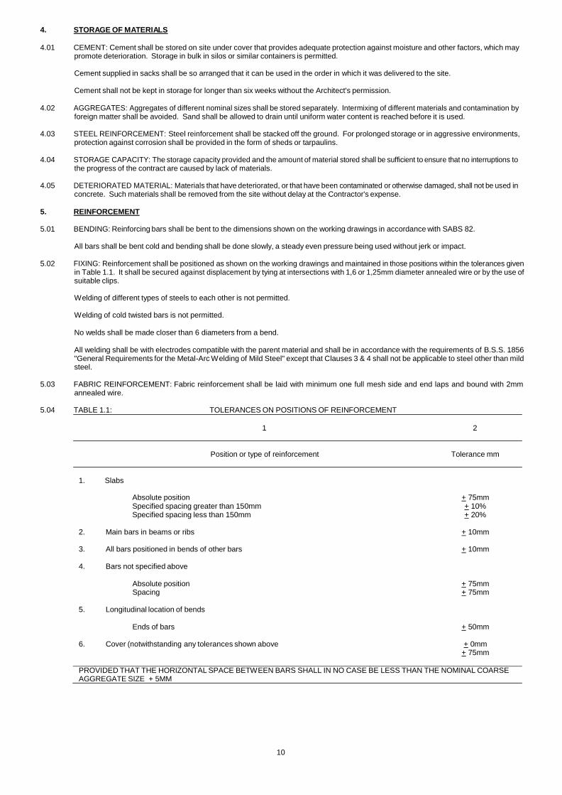
5.04 TABLE 1.1: TOLERANCES ON POSITIONS OF REINFORCEMENT
1 2
Position or type of reinforcement Tolerance mm
1. Slabs
Absolute position + 75mm Specified spacing greater than 150mm + 10% Specified spacing less than 150mm + 20%
2. Main bars in beams or ribs + 10mm
3. All bars positioned in bends of other bars + 10mm
PROVIDED THAT THE HORIZONTAL SPACE BETWEEN BARS SHALL IN NO CASE BE LESS THAN THE NOMINAL COARSE AGGREGATE SIZE + 5MM
11
5.05 SPACERS AND LIFTING BLOCKS: The Contractor shall provide spacers or lifting blocks in order to form and maintain the cover as required in Clause under the heading "Cover" below. The prices for reinforced concrete shall include for spacers and lifting blocks. The price may exclude lifting blocks for supporting top reinforcement in ordinary slabs and cantilevers for which adequate stools have been detailed, but it shall include the lifting blocks required to provide the cover to the stools themselves.
Neither the inclusion of stools in the details nor the possible omission of stools from the detail s shall relieve the Contractor of his responsibility for maintaining any steel in the position intended by the details. In the case of stools omitted from the details the Contractor will be paid for the supply of these at the rates priced for the reinforcement.
5.06 COVER: The minimum concrete cover to any reinforcement will be as specified on the drawings. Unless otherwise specified the minimum
concrete cover to reinforcement at faces exposed to earth or water in the finished works shall be 75mm. Elsewhere the minimum concrete cover shall be 12mm in slabs, 25mm in beams and 40mm in columns unless otherwise specified.
5.07 SPLICING: Splicing or joining of reinforcing bars shall be made only as and where shown on the working drawings. Welding will only be
permitted subject to the limitations stated above.
5.08 PROTECTION OF EXPOSED BARS: Reinforcement exposed for future bending of extensions to the works, shall be protected from corrosion as follows.
remove all rust,
treat with an approved quality rust remover,
apply one coat of an approved quality zinc rich cold galvanising paint.
6. FORMWORK
6.01 DESIGN: Formwork shall be so designed and constructed that the concrete can be properly placed and compacted and that the required
shapes, positions, levels and dimensions of the concrete work shown on the drawings are maintained, subject to the tolerances given in Table 1.2, due attention being paid to the accumulation of error when modular formwork is used.
The formwork and its supports (together referred to as formwork) shall be capable of resisting with an adequate factor of safety all construction loads, wind forces and all other superimposed loads and forces. Supports shall be adequately braced and suitable precautions shall be taken to protect the formwork against possible impact. The construction shall allow for stripping without jarring or damaging the concrete.
Joints in forms shall be right enough to prevent leakage of cement paste. Wedges and clamps shall be used in preference to nails. Tie rods are preferable to wire ties. This specification calls for vibrated concrete and adequate cognisance shall be taken of this in the design of the formwork.
6.02 CLASSES OF FINISH FOR FORMWORK
FINISH: The classes of finish shall be:
CLASS F1: This finish shall be for surfaces against which backfilling will be placed or which will be plastered. Formwork shall consist of sawnboards, sheet metal or any other suitable material, which will prevent the loss of grout when the concrete is compacted.
CLASS F2: This finish shall be for surfaces, which are permanently exposed to view but where the highest standard of finish is not required. Forms to provide a Class F2 finish shall be faced with wrought and thicknessed boards with square edges arranged in a uniform pattern. Alternatively, plywood or metal panels may be used if they are free from defects likely to detract from the general appearance of the finished surface. Joints between boards and panels shall be horizontal and vertical unless otherwise directed.
This finish shall be such as to require no general filling of surface pitting, but fins, surface discoloration and other minor defects shall be remedied by methods approved by an Architect.
CLASS F3: This finish shall be for surfaces, which are permanently exposed to view and where good appearance and alignment are of prime architectural importance. To achieve this finish the formwork must be constructed to fine limits of accuracy, and may be of timber or steel or other material capable of fulfilling the particular requirements. Moreover, it shall be jointed in such a way as to maintain accurate alignment. Where timber is used it shall be from well-weathered stock and obtained form one source only to ensure equal moisture content resulting in equal absorbency rates. In this case no formwork may be wired through except with the permission of the Architect who must agree also with the positions and patterning of all nails used. The positions and sizes of any holes that may be required fo r formwork supports must meet with the Architect's approval, and for this purpose asbestos-cement ferrules shall be used.
Rates must include for the casting faces of all such formwork being thoroughly re-treated with approved mould oil, which shall be soluble or emulsifiable in water.
RE-USE OF FORMWORK: Immediately a shutter is struck, it is to be thoroughly cleaned with wire brushes and given a coat of mould oil; before re-use, all formwork shall be reconditioned, and all form surfaces that are to be in contact with the concrete shall be thoroughly cleaned again without unduly damaging the surfaces of the formwork.
6.03 TABLE 1.2 : TOLERANCES ON CONCRETE WORK
12
1
2
ITEM OF CONCRETE WORK
TOLERANCES
+ 10mm, - 5mm 1. Depth of slabs and thickness of walls
The greater of +2%, - 1% or + 10mm,
2. Cross-sectional dimensions of beams, ribs and columns - 5mm but not greater than ± 25mm
3. Variation from plumb of vertical surfaces and edges 1 in 600 maximum 20mm
4. Footings : On plan dimensions ± 75mm
but not exceeding an area: ± 5% On centre ± 25mm
5. Deviation from line on any edge or surface:
(Percentage given with respect to length of line)
Where wet finishes are to be applied or where dry finishes are ± 0,2% but not more than 10mm continuous with the member
Where member will not be exposed to view ± 0,3% but not more than 10mm
For off-shutter exposed work ± 0,1% but not more than 5mm
NOTE: Where formwork is permanently exposed to view no deviation at junctions of shutters will be permitted
6. The level of any part of the structure shall be within 10mm of the specified level, provided also that the mean difference in level
between successive specified levels does not differ from the derived difference by more than 10mm.
7. Except as specified for footings the plan position of any point in the structure is permitted to vary from its specified position by a
maximum of 25mm provided the variation of its position with respect to its corresponding feature on the next lower and/or higher specified level does not exceed 1/600 (one six-hundredth) of the difference in level or 3mm whichever is the greater.
8. On all dimensions other than given above: ± 0,1% but not less than
± 3mm nor greater than ± 15mm
9. Where concrete is constructed to receive precast elements it shall be the Contractors responsibility, in addition to the requirements of the above, to ensure that the concrete structure is constructed with due regard to the compatibility with the precast elements it is intended to receive.
6.04 CAMBER: Unless otherwise detailed on the drawings, beams and slabs shall be constructed with the following upward cambers:
at midspan of roof beams and slabs : 2mm per meter span at midspan of floor beams and slabs : 1mm per meter span at free end on cantilevers : 4mm per meter span
6.05 TIES: The types of ties used and their position shall be such that the finish required is achieved and is not marred by subsequent corrosion.
Ties shall not cause holes to be formed in excess of 100mm5 in cross-sectional areas shall be plugged with a 2:1 sand/cement mortar.
6.06 PREPARATION OF FORMWORK: Surfaces that are to be in contact with fresh (wet) concrete shall be so treated (by coating with a non-
staining mineral oil or other approved material or in the case of timber forms) so as to ensure easy release and non-adhesion to formwork during stripping. Every precaution shall be taken to avoid contamination of the reinforcement during this application.
Surfaces, which are to receive concrete, shall be thoroughly cleaned of all foreign matter before casting.
6.07 OPENINGS: Where necessary for cleaning, inspection, or placing purposes temporary openings shall be provided in the formwork.
6.08 COFFERED SLABS: The formwork to the coffers shall be constructed of mild steel sheet, fibreglass, or other approved material, which will
leave the exposed concrete surfaces true and acceptable. The formwork to the longitudinal and latitudinal ribs to the beams of the coffered slabs is measured separately but the Contractor is at liberty to construct these in a different manner if he so desires, on condition that the resultant effect is acceptable to the Architect.
The Contractor is solely responsible for the design and erection of the formwork for the coffered structure and he must ensure that its quantity is sufficient for his intended working progress and that its quality is adequate to satisfy the specification for general formwork.
In addition, the Contractor must submit to the Architect, for approval, if called upon to do so, complete detailed shop drawings of all formwork, etc., necessary for the construction of the coffered structure.
6.09 REMOVAL OF FORMWORK: Formwork shall not be removed before the concrete has attained sufficient strength to support its own mass and any loads that may be imposed on it. This condition requires the formwork to remain in place, after placing of the concrete, for a period not less than the appropriate time given in Table 1.4 (as may be relevant to the type of cement used);
13
or when the concrete has attained the appropriate strength shown in Table 1.4. The Contractor shall support the use of the latter method with adequate strength/maturity curves.
Formwork shall be removed carefully so that shock and damage to the concrete are avoided. It should be noted that Table 1.4 specifies minimum times. These must be increased in the case of special finishes, which may be sensitive to damage.
Weather may be regarded as 'normal' when the mean atmospheric temperature adjacent to the concrete, as measured by a maximum and minimum thermometer, does not fall below 5°C. When mean temperatures are between these values, stripping times shall not be less than the intermediate value determined by linear interpolation between the specified periods.
6.10 TABLE 1.4 : REMOVAL OF FORMWORK : MINIMUM TIME IN DAYS
(Dependent on compliance with the Clause "Adverse Weather Conditions")
1.
2.
3.
1 2 3 4 5 Type of Cement used
6 7 8
OPC PC15
RHPC PBFC Alternative strength as % of
WEATHER WEATHER WEATHER 28-day strength N C N C N C
Beam sides; walls; u Columns less tha thick; Coffers to coffered s
nloaded n 300mm labs (I)
2
3
1
2
3
4
20%
Ditto but not less th thick
an 300mm
1
2
1
2
2
3
20%
Slabs with props left
under (ii)
4
7
2
4
6
10
40%
4. Beam soffits with under
props left 7 12 3 5 10 17 60%
5. Slab props; props ribbed floor
to ribs of 10 17 5 9 10 17 70%
6. Beam props 14 28 7 12 14 28 80%
N = Normal; C = Cold as defined above.
i) Application to coffers of which the shorter plan dimension does not exceed 1,500mm and provided propping is left under the ribs.
ii) Including slabs formed by coffers to which the shorter plan dimension exceeds 1,500mm.
The Contractor shall not impose construction loads on slabs and beams in excess of the design loads shown on the drawings and shall retain the propping in position until such loads are adequately accommodated. Where floor construction is required to support subsequent floor construction over, the new construction shall be supported by means of propping the number of floors shown in Table 1.5. Such props shall be placed vertically above each other through the required number of floors.
6.11 TABLE 1.5 : NUMBER OF SUPPORTING FLOORS
Construction Cycle Number of Floors Providing Support
Time in Days Hot Weather Cold Weather
10 to 13 2 3
14 and Over 2 2
7. CONCRETE QUALITY
7.01 GENERAL: The Contractor will be responsible for the design of the concrete mix and for the proportions and suitability of its constituent materials necessary to produce concrete that complies with the requirements set out in Table 1.6.
Due consideration shall be given to the production of concrete with minimal bleeding, segregation and shrinkage characteristics. The Contractor shall carry the entire responsibility for any defects that may arise form bleeding and/or drying shrinkage of the concrete unless such defects flow from construction procedures stipulated by the Architect to which the Contractor has objected in writing.
See also "Size of Cast" defined below.
The concrete shall have maximum density and minimum free water content consistent with the required strength and workability.
14
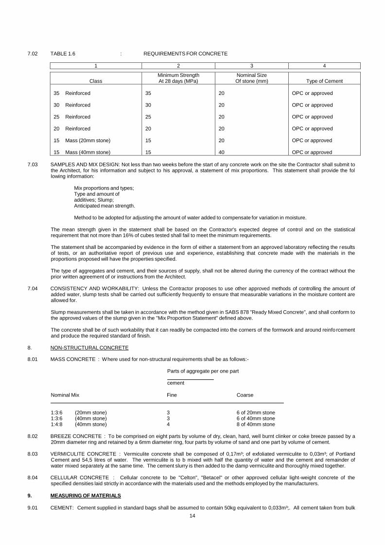
7.02 TABLE 1.6 : REQUIREMENTS FOR CONCRETE
1 2 3 4
Class
Minimum Strength At 28 days (MPa)
Nominal Size Of stone (mm)
Type of Cement
35 Reinforced
30 Reinforced
25 Reinforced
20 Reinforced
15 Mass (20mm stone)
15 Mass (40mm stone)
35
30
25
20
15
15
20
20
20
20
20
40
OPC or approved
OPC or approved
OPC or approved
OPC or approved
OPC or approved
OPC or approved
7.03 SAMPLES AND MIX DESIGN: Not less than two weeks before the start of any concrete work on the site the Contractor shall submit to the Architect, for his information and subject to his approval, a statement of mix proportions. This statement shall provide the fol lowing information:
Mix proportions and types; Type and amount of additives; Slump; Anticipated mean strength.
Method to be adopted for adjusting the amount of water added to compensate for variation in moisture.
The mean strength given in the statement shall be based on the Contractor's expected degree of control and on the statistical requirement that not more than 16% of cubes tested shall fail to meet the minimum requirements.
The statement shall be accompanied by evidence in the form of either a statement from an approved laboratory reflecting the r esults of tests, or an authoritative report of previous use and experience, establishing that concrete made with the materials in the proportions proposed will have the properties specified.
The type of aggregates and cement, and their sources of supply, shall not be altered during the currency of the contract without the prior written agreement of or instructions from the Architect.
7.04 CONSISTENCY AND WORKABILITY: Unless the Contractor proposes to use other approved methods of controlling the amount of
added water, slump tests shall be carried out sufficiently frequently to ensure that measurable variations in the moisture content are allowed for.
Slump measurements shall be taken in accordance with the method given in SABS 878 "Ready Mixed Concrete", and shall conform to the approved values of the slump given in the "Mix Proportion Statement" defined above.
The concrete shall be of such workability that it can readily be compacted into the corners of the formwork and around reinfo rcement and produce the required standard of finish.
8. NON-STRUCTURAL CONCRETE
8.01 MASS CONCRETE : Where used for non-structural requirements shall be as follows:-
Parts of aggregate per one part
cement
Nominal Mix Fine Coarse
1:3:6 (20mm stone) 3 6 of 20mm stone 1:3:6 (40mm stone) 3 6 of 40mm stone 1:4:8 (40mm stone) 4 8 of 40mm stone
8.02 BREEZE CONCRETE : To be comprised on eight parts by volume of dry, clean, hard, well burnt clinker or coke breeze passed by a
20mm diameter ring and retained by a 6mm diameter ring, four parts by volume of sand and one part by volume of cement.
8.03 VERMICULITE CONCRETE : Vermiculite concrete shall be composed of 0,17m³; of exfoliated vermiculite to 0,03m³; of Portland Cement and 54,5 litres of water. The vermiculite is to b mixed with half the quantity of water and the cement and remainder of water mixed separately at the same time. The cement slurry is then added to the damp vermiculite and thoroughly mixed together.
8.04 CELLULAR CONCRETE : Cellular concrete to be "Celton", "Betacel" or other approved cellular light-weight concrete of the
specified densities laid strictly in accordance with the materials used and the methods employed by the manufacturers.
9. MEASURING OF MATERIALS
9.01 CEMENT: Cement supplied in standard bags shall be assumed to contain 50kg equivalent to 0,033m³;. All cement taken from bulk
15
storage containers and from open or partially used bags shall be batched by mass, the weighing device having an accuracy within 2 percent of the mass of cement required for the batch.
9.02 WATER: Mixing water for each batch shall be measured, either by mass or by volume, to an accuracy of within 3 percent.
9.03 AGGREGATES: Aggregates shall be gauged by mass, the weighing devices being maintained in good order and having an
accuracy within 5 %.
10 MIXING
10.01 GENERAL: Mixing of materials for concrete shall be conducted by experienced operators. Unless otherwise approved, mixing shall be carried out in a mechanical batch-mixer of approved type and capable of producing a uniform distribution of ingredients throughout the batch.
10.02 CHARGING THE MIXER: A fixed sequence of charging shall be maintained and shall be subject to the approval of the Architect.
10.03 MIXING AND DISCHARGE: Mixing shall be continued for a period sufficient to ensure a uniform blending of all ingredients. The mixer
shall be operated at the speed recommended by the manufacturer. Each batch shall be completely discharged before recharging the mixer.
10.04 MAINTENANCE AND CLEANING OF MIXER : If the mixer has stopped running for any period in excess of 30 minutes, it shall be
thoroughly cleaned out, particular attention being paid to the removal of any build-up of materials in the drum, in the loader, and around the blades or paddles. Worn or bend blades and paddles must be replaced.
10.05 READY MIXED CONCRETE: The appropriate and relevant requirements of SABS 878 "Ready Mixed Concrete" shall apply in
preference to those given in this section if concrete is delivered to the site "ready mixed".
11. PUMPED CONCRETE
Concrete may only be pumped with the written approval of the Architect. If approval for the use of pumped concrete is given in principle, a copy of the design mix must be supplied 3 weeks prior to use for the Architect's approval.
In addition, pumped concrete shall be required to have design strength 15% in excess of the strength specified. All extra costs shall be borne by the Contractor.
12. TRANSPORTING AND PLACING
12.01 SIZE OF CAST : In establishing the size of any one cast the Contractor shall give due consideration to and will be solely responsible for defects which may arise from drying shrinkage or bleeding of the concrete unless such defects flow from construction procedures stipulated by the Architect to which the Contractor has objected in writing.
12.02 TRANSPORTING: Mixed concrete shall be discharged from the mixer and transported to its final position in such a manner tha t
segregation, loss of ingredients, and adulteration are prevented. The mix shall be of the required workability at the point and time of placing.
12.03 PLACING: The Contractor shall give the Architect at least 24-hour notice of his intention to place concrete. The concrete shall be placed in its final position in the forms before loss of workability occurs but in no case in excess of one hour from the time of discharge from the mixer. Pretempering by the addition of water or other material is not permitted. The forms to be filled shall be clean internally. Excavations and contact surfaces of an absorbent nature shall be dampened but no free water shall be permitted to remain.
Wherever possible the concrete shall be deposited vertically into its final position and care shall be taken to avoid segregation and displacement of reinforcement and other embedded items.
The working of deposited concrete (whether by means of vibrators or otherwise) to cause it to flow laterally is prohibited. The concrete shall be brought up in horizontal layers and continuously vibrated or tamped and "heaping" shall be avoided.
Where chutes are used to convey the concrete, their slopes shall be such as not to cause segregation and suitable spouts or baffles shall be provided for the discharge of the concrete. Chutes shall be suitable "primed" in a manner similar to that specified for the mixer above.
Concrete shall not be allowed to fall freely through a height of more than 3 000mm, and it shall not be placed in water (standing or running) unless so approved. Where it is required to deposit concrete through a height exceeding 3 000mm, suitable chutes shall be provided for the full drop. Casings or driving tubes for lightly reinforced piles will be considered in suitable chutes.
Where the method of construction so requires, the Contractor shall provide approved runways for the distribution of concrete to the various parts of the beams and slabs. Such runways shall be solidly constructed and of sufficient width and height to obviate the po ssibility of interference with the steel reinforcement.
12.04 COMPACTION : The concrete shall be thoroughly compacted during and immediately after placing. Compaction shall be carried out by
mechanical vibration or (if approved) by spading, rodding, or forking. Over-vibration resulting in segregation, surface laitance, or leakage (or any combination of these) shall be avoided.
12.05 CONSTRUCTION JOINTS : Concreting shall proceed uninterrupted up to stopping points shown on the drawings or as approved. A ll
construction joints inclined at an angle sufficient to cause an uncontrollable flow of the concrete during compaction shall be formed against a face, which will prevent flows and excess loss of mortar.
If, in an emergency, concreting has to be interrupted, a construction joint shall be formed which will least impair the durability, appearance, and functioning of the concrete. If in the opinion of the Architect the construction joint so formed is not suitable, the Contractor shall at his own expense modify the joint to the satisfaction of the Architect.
The Contractor shall obtain approval of size, position and methods of making good of any temporary openings required.
When bonding fresh concrete to old concrete (and where applicable), hack away any projecting stones or fins of concrete and cut back to solid concrete. Remove any mortar leakage, which may have occurred. Clean away all loose material. Thoroughly damp down old surface (24 hours soaking where concrete is more than 3 days old) and cover with a 10mm thick layer of mortar composed of cement and sand
16
mixed in the same ratio as the cement and sand in the concrete mixture. The mortar shall be freshly mixed and placed immediately before the placing of new concrete.
Prices of concrete to include for all necessary construction joints, including for the provision of all necessary formwork, templates for passage of reinforcing rods and dowels, etc.
12.06 CURING AND PROTECTION : Formwork shall be retained in position for the appropriate period given and, as soon as it is practicable in the opinion of the Architect, all concrete shall be protected from contamination and loss of moisture by one or more of the following methods:
Ponding the exposed surfaces by means of water, except where atmospheric temperatures are low, i.e. less than 5°C;
covering with sand, sawdust, or mats made of a moisture-retaining material, and keeping the covering continuously wet;
continuous spraying of the exposed surface with water;
covering with a waterproof or plastic sheeting firmly anchored at the edges;
using an approved curing compound.
Intermittent hosing by hand will not be permitted.
Whatever method of curing is adopted, its application shall not cause staining, contamination or marring of the surface of the concrete.
The curing period shall be at least 5 days for concrete made with Portland cement, at least 3 days for that made with rapid -hardening Portland cement, and at least 7 days if Portland blast furnace cement is used. When average atmospheric temperatures are below 5°C these minimum-curing periods shall be extended by 3, 2 and 4 days respectively.
13. ADVERSE WEATHER CONDITIONS
13.01 COLD WEATHER: When the surrounding atmospheric temperature falls below 5°C, effective measure shall be taken to ensure tha t the
temperature of the concrete from the time of placing is maintained above 5°C for 5 days. All surfaces shall be protected from ice or frost damage.
13.02 HOT WEATHER: When the surrounding atmospheric temperature is over 32°C, the temperature of the concrete when deposited shall not
be allowed to exceed this figure. Stockpiles of aggregates and all metal contact surfaces shall be shielded from the direct rays of the sun or cooled by spraying water.
14. ENGINEER DESIGNED CONCRETE FLOORS
14.01 GENERAL : This work shall consist of construction Engineer designed reinforced concrete floors.
14.02 STRENGTH : The concrete shall, unless otherwise described, be so proportioned as to give cube strength of 30MPa at 28 days. The slump shall be between 40mm and 75mm.
14.03 FORMS : Forms shall be of steel or wood dressed on the top and inside. They shall have a height equal to the slab thickness. Built-up,
battered, bend, twisted or broken forms shall be removed from the work. All forms shall be cleaned and oi led each time they are used. Forms shall be constructed and set as to resist, without springing or settlement, the pressure of the concrete and the operation of the finishing machines.
14.04 PANELS : Concrete shall be placed in panels of specified sizes. Casting shall be in chequer-board pattern or shall be in long lanes and
saw cut to the required size within 12 hours after concreting. The precise details of the panel sizes and method of construction must be discussed with the Architect before the work is commenced.
14.05 REINFORCEMENT : The panels are to be reinforced with high tensile steel mesh fabric to SABS 1024 as specified. A cover of 29mm of
concrete must be provided above the steel reinforcement. The mesh reinforcement shall be terminated 70mm on either side of all construction joints and saw cut contraction joints (i.e. no reinforcement must pass through any joints at all).
Reinforcement is measured separately.
14.06 CONCRETE PLACING : Concrete shall not be placed until the sub-grade is prepared and the forms are set. Concrete shall be deposited
on polythene sheets (measured separately) with a minimum of re-handling and in one layer. Spading or vibrating shall be done adjacent to forms and joints.
The concrete shall be placed continuously between construction joints, beginning at edges, corners, etc. Each batch shall be placed into the edge of the previously placed concrete to avoid stone pockets and segregation. If there is a delay in casting, the concrete placed after the delay shall be thoroughly spaded and consolidated at the edge of that previously placed to avoid cold joints. Concrete shall be distributed by shovels and consolidated by vibration. The concrete shall then be brought to correct level with a straightedge or roller and struck off, leaving it free of humps or hollows.
14.07 POWER FLOATING : After the concrete has been properly placed, struck off and tamped or rolled, it shall not be worked until ready for
floating. The lapse of time between tamping and power floating may vary from 2 to 8 hours or more depending on weather conditions, concrete temperature, and concrete mixture. Floating shall begin when the water sheen has disappeared or the mix has stiffened enough so that the weight of a man standing on it leaves only a slight imprint on the surface. If two power floating operations are necessary to bring the surface to the desired state, the concrete shall be allowed to stiffen or become harder before beginning the second floating operation.
When a dry shake is specified, the selected metal or mineral aggregate for the dry shake shall be applied immediately before power floating begins. Approximately two-thirds of the selected material for required coverage shall be broadcast uniformly over the surface. Power floating shall begin immediately after application of the dry shake. After this material is adequately embedded or blended into the surface by power floating, the remaining material shall be applied to the surface at right angles to the previous ap plication. During the second application care should be exercised to apply sufficient material to all areas to secure uniform coverage.
17
Sprinkling dry cement or a mixture of dry cement and sand on the surface of the fresh concrete to absorb water or to stiffen the mix shall not be permitted during any stage of floor construction.
Power floating shall continue until the surface attains an even, fine matt texture.
Power floating is measured separately. 14.08 SURFACE TOLERANCES : The maximum variation in surface tolerance for power floated floors shall be 3mm in 3 000mm. If variations
greater than this exist, the Architect may direct the Contractor to grind the floor, at his own cost, to bring the surface within the requirements. Patching of low spots shall not be permitted. Grinding shall be done as soon as possible, preferable within 3 days, but not until the concrete temperature is sufficiently strong to prevent dislodging coarse aggregate particles.
14.09 CURING AND PROTECTION: All freshly cast concrete shall be protected from damaging effect of the elements - freezing, rapid drop in
temperature and loss of moisture - and from future construction operations. When necessary, the Contractor shall provide and use insulation and tarpaulins to maintain the concrete temperature above 10°C for the first week.
The concrete shall not be permitted to dry during the curing period of 7 days. If the floor is left uncovered during the curing period, a film of water shall be clearly visible at all times on the entire surface of the slab. If the film of water cannot be maintained the slab shall be covered with curing paper meeting the requirements of Specifications for Waterproof Paper for Curing Concrete (ASTM C171), or other c uring material as approved by the Architect, and shall be left on the slab for the entire curing period.
If, at any time during the progress of work the temperature is below 4°C, the Contractor shall make suitable provision to protect the concrete. This protection shall consist of the use of insulating materials, such a blankets or mater, and equipment for providing artificial heat. Heaters shall be placed in the building prior to concreting to maintain the temperature above 10°C and to remove any frost from the sub grade.
A thermometer accurate to plus or minus 1°C shall be placed on the surface of the slab under the curing blanket to record the temperature. If the temperature at this position falls below 10°C, additional insulation material shall be supplied to maintain the temperature above 10°C. If heaters are used, precautions shall be taken to prevent drying of the slab. Water jackets or other suitable devices shall be provided on all heaters to maintain the relative humidity of the atmosphere as high as possible.
After the curing period, the temperature of the exposed surface shall not be permitted to drop faster than 16°C in 24 hours.
In hot weather suitable precautions shall be taken to avoid drying of the slab prior to the finishing operation. Windbreaks, and/or sunshades shall be provided as directed by the Engineer. During extremes in weather, floors shall not be cast unless a roof protects the slab and other suitable protective measures can be taken.
After the curing has been completed, the floor shall be exposed to the air for at least 48 hours prior to allowing traffic on it.
Striking off and curing is measured separately, but Tenderers shall include in their rates for all protective measures described above.
14.10 CONSTRUCTION AND CONTRACTION JOINTS:
a) All construction joints must be formed with keys and/or dowel bars. b) Slope of key to be 1:4.
c) Dowel bars to be 20mm diameter and 300mm long and to be cast in at 30mm centres. Only the embedment length (150mm) must be founded in the concrete - the remaining length of the bar must be free to permit unrestricted movement of the slabs.
Dowel bars must be placed normal to the face of the construction joint and strictly true and parallel.
d) Designed construction joints are measured separately.
14.11 SAW CUT (CONSTRUCTION JOINTS):
a) All construction joints, whether transverse or longitudinal, must have sawn joints.
b) All joints to be 6mm wide x 15mm deep unless otherwise specified and sealed with a sealant to the approval of the Architect.
c) Saw cut joints and polysulphide sealants are measured separately.
14.12 SEALING: In all cases, it is advisable to wait as long as possible before sealing joints. Sides of joints to be protecte d against spilling of sealant by masking with an approved method and the prices for the sealants are to include for this.
14.13 BACK-UP STRIPS:
a) All back-up strips to be of polyethylene or polyurethane foam.
b) Back-up strips must be painted with a bond breaker. (The sealant must not adhere to the back-up strip).
14.14 PRICES : Prices for concrete in Engineer designed concrete floors must include for casting in panels, vibrating, pipe-rolling, finishing
to exact levels within the allowable tolerances, infilling around columns including vibrating and any additional cost of hand-operations, and for casting, etc. after all manholes, services and drains have been installed.
15. POWER FLOATING TO SUSPENDED SLABS
15.01 Where power floating is specified as the finish to concrete suspended slabs the specifications applic able to power floating under
the heading "Engineer Designed Concrete Floors" and the tolerances thereto shall apply.
18
16. CONSTRUCTION DETAIL
16.01 HOLES, CHASES AND BUILT-IN ITEMS: No holes or chases other than those shown on the drawings or approved by the Architect shall be cut or otherwise formed in concrete.
No items for the attachment of fixtures shall be embedded in the concrete unless approved by the Architect.
Built-in items shall be positioned in accordance with the relevant tolerances specified in the clause "Design" (under the heading "Formwork") and shall be securely held in position during concreting. Unless otherwise shown on the drawings, items which are to be incorporated into cambered members shall be suitable curved to match the required camber.
16.02 PIPES AND CONDUITS: No pipes or conduits other than those shown on the drawing shall be embedded in the concrete without
approval. The clear space between any such pipes and the clear distance between such a pipe and any reinforcement shall be at least 40mm or the maximum size of the coarse aggregate plus 5mm, whichever is greater. The amount of concrete cover over pipes and fittings shall be at least 25mm.
16.03 EXPANSION JOINTS : Expansion joints shall be formed as shown on the drawings. Adequate care shall be taken to ensure that any joint
filler will be securely retained or easily removed, as may be required.
16.04 WATERBARS: All waterstops shall be thoroughly cleaned immediately before they are embedded in concrete. Formwo rk shall be constructed to accommodate and support waterstops in their correct and final positions. No nails shall be used and no holes shall be made through waterstops in order to support them. When concrete is placed near waterstops, care shall be taken that waterstops are not deformed or displaced. The concrete shall be carefully vibrated into position around waterstops and special care shall be ta ken to ensure the concrete is completely compacted around waterstops. Waterstop strips shall be provided in long lengths and shall be installed with a minimum number of joints. If waterstop strips have to be joined this shall be carried out to the satisfaction of the Architect. Exposed rolls of waterstop strips shall be protected against weather and damage. The Contractor shall ensure that all junctions of waterstops are perfectly watertight.
16.05 PATCHING: After removal of the forms, if the concrete shows any defect or if subsequently any defect attributable to the qual ity of the
concrete or its constituents shall develop, the Contractor shall at his own cost, on and in accordance with instructions from the Architect, remove all defective concrete and replace it or make good such defects. No patching or making good shall be carried out by the Contractor without the prior approval of the Architect.
16.06 GROUTING UNDER STEELWORK, ETC. : The Contractor will be called upon to grout up under structural steel base plates and similar
structures. All such grouting is to be done with cement mortar mixed in proportions of one part cement to two parts sand and in thicknesses varying from 12mm upwards.
Before any grouting is done, the top and bottom surfaces between which the grout is to be placed, must be made absolutely clean and the concrete surface must be soaked with water. The grout shall be of damp consistency and shall be rammed into place with suitable hand tools.
17. TESTS
17.01 SAMPLING, TESTING IN GENERAL AND CERTIFICATES: The Architect shall have free access to the work for the selection of samples
and for carrying out tests. The Contractor shall render any assistance necessary for the taking of the samples and for carrying out the tests. If so required, the Contractor shall provide storage and protection for such samples on the site.
The Contractor shall provide manufacturer's test certificates if called upon to do so by the Architect. Such certificates shall be submitted within 14 days of request. The need of such certificates shall be borne in mind at the time of placing orders.
17.02 COMPRESSIVE STRENGTH: During the time in which each class of concrete is being placed, samples of the concrete shall be taken at
the point of placing at the rate of at least one sample from each 75m³. A group of six 150mm test cubes shall be made from each sample. Each group of test cubes shall be deemed to represent the whole of the concrete from which the sample was taken and shall be identifiable with the concrete.
From each group, 3 cubes shall be tested at 7 days and 3 cubes at 28 days during the initial period of the Contract and until a stable relationship between the 7-day and 28-day strength is established. At this stage a minimum 7-day strength in lieu of the specified minimum 28-day strength will be established by the Architect for determining the need for extended period of time as set out below. If results of 7-day tests are satisfactory the Architect may waive the testing of the remaining 3 cubes of the group at 28 days.
The procedure for sampling, making the test cubes, curing, storing and testing, and the moulds used, shall be in accordance with SABS Method 863 "Compressive strength of concrete". The Contractor shall provide sufficient moulds required for the making of test cubes.
Cores which may be drilled in terms as defined hereafter shall be tested as specified in accordance with SABS Method 865 "The drilling, preparation and testing of concrete cores".
Compressive tests shall be carried out by an independent authority adequately equipped for such testing.
Results of non-destructive tests supported by instrument calibration certificates of the Portland Cement Institute or the South African Bureau of Standards or the National Building Research Institute or as otherwise calibrated by agreement between the Contractor and the Architect, shall have the same force as compressive tests.
17.03 GRADING ANALYSIS : The Architect may at any time call for a grading analysis to be made by an independent authority for each of the
aggregates used. The analysis shall be made by the method given in SABS 1083 "Aggregates for Concrete".
17.04 DETERMINATION OF CONSISTENCY : The slump test used to measure the consistency of the concrete mix shall be carried out in accordance with SABS Method 862 "Slump of freshly mixed concrete".
17.05 BULKING OF FINE AGGREGATES: When batching allowance is to be made for the bulking of fine aggregates.
19
17.06 COST OF TESTS : The costs of all tests required by the Architect shall be borne by the Employer, either as may be specifically measured in the Bill of Quantities or allowed for as an extra to the contract, except that the costs of the following tests plus incidental expenses related to such tests shall be borne by the Contractor and shall be deemed to have been allowed for in the rates.
Slump Tests; Preliminary tests required; Bulking tests; Such tests (including core or load tests) as may, in the opinion of the Architect, be made necessary by failure on the part of the Contractor to meet the requirements of these preambles;
Any tests which fail to meet the requirements of these preambles.
18. FAILURE
18.01 APPEARANCE : If, in the opinion of the Architect, any concrete finishes (other than finishes which are not exposed to view) do not match up to the requirements of these preambles these shall be deemed to have failed.
18.02 DIMENSIONS : Any dimensions, which are found to be in error in excess of the specified tolerances, shall be deemed to be a failure.
18.03 CONCRETE STRENGTH : Concrete from which test cubes have been prepared shall be considered as having failed if the compressive
strength (being the arithmetic mean of the results of tests on at least 3 cubes) at 28 days is less than the minimum specified. If in calculating the strength it is found that the difference between the highest and lowest cube results exceeds 20 per cent of the mean of the three cubes, the results may, at the discretion of the Architect be discarded. Results so discarded may be deemed to be a failure on the part of the Contractor to meet the requirements of these preambles and/or a test, which failed to meet the requirements specified.
Concrete which exhibits defects as a result of poor workmanship, over-loading, fibre, premature removal of formwork, bleeding or drying shrinkage shall be considered as having failed.
18.04 STRENGTH OF STRUCTURE: The structure or any part of the structure will be deemed to have failed if: It
contains concrete, which has failed; Its reinforcing steel sizes, quantities, strength or positions are at variance with the requirements of the detail drawings or these preambles; It contains concrete members whose dimensions differ from the specified dimensions including tolerances so as to reduce the strength.
19 REMEDIAL ACTION
19.01 CONDONEMENT : The Architect, in his sole discretion, and without prejudice towards any other failures, and without giving any reasons
therefore may condone any failure.
In condoning any failure of a strength test the Architect will take the following into consideration:
The technical reasons for the failure; The statistical reasons for the failure; The probability of recurrence if no change is made in mix proportions, production control and methods of sampling and tests; The actual stresses to which the portion of structure, represented by the test, will be subjected; The probability of overload of the portion of structure represented by the test; The statistical requirement that not more than 16% of al cubes tested may fail; The pattern of results achieved up to the time of failure.
19.02 APPEARANCE DEFECT: Concrete, which has been deemed to have failed, shall be repaired or removed and replaced.
19.03 DIMENSIONAL DEFECT : Concrete, which has failed in terms of the clauses where applicable, shall be treated as follows:
In the case of members of excessive size, excess material shall be removed subject to this procedure not resulting in a weakening of the member for other reasons or adversely affecting the appearance. If the member would be weakened or its appearance affected, it shall be repaired or removed and replaced.
In the case of undersized members, be treated as for "Strength Defect" if applicable or it shall be built up to the required size subject to this procedure not affecting the appearance. If its appearance would be affected it shall be repaired or removed and replaced.
Notwithstanding the foregoing requirements of this clause if modification of the members can be avoided by the alteration of other components, this will be permitted provided it does not affect strength or other considerations.
19.04 STRENGTH DEFECT: Where concrete has failed in terms of the above clauses the Architect may call for any or all of the foll owing
remedial measures to be implemented:
Change the materials or portions of the concrete mixture to avoid a future recurrence of the defect.
Forthwith extend the periods of time given for the removal of formwork up to a maximum of 14 days extension and/or up to a maximum of 28 days extension.
Drill and test concrete cores and/or perform non-destructive tests.
Strengthen the defective portion.
20
Remove and replace such non-defective portions as may be required for the purposes of strengthening or removal and replacement of defective portions.
Carry out load tests in terms of Regulation 5 of Chapter 5 of the SABS "Standard Building Regulations".
19.05 COSTS: Where the Contractor is found to be responsible for any failure all costs resulting from such failure shall be borne by him, including
but not limited to the following:
The cost of all tests required for establishing the nature of the failure and the ultimate adequacy of the portion in question;
Professional fees incurred by the Employer as a result of the failure;
All costs incurred in strengthening opening up, removal and replacement as applicable;
The cost of removal, reinstatement or modification of other components where necessary.
20 PRICES OF CONCRETE, FORMWORK AND REINFORCEMENT
20.01 IN-SITU CONCRETE : Prices of all in situ concrete must include for mixing, hoisting and lowering to all levels, placing, working around
reinforcement, vibrating and compacting.
20.02 FORMWORK : The prices of all formwork must include for use, waste, all straight, square and rake cutting, splayed edges, intersections, struts, hangers, etc., horsing up, wedging, maintaining, easing, striking and removing as and when directed, except where described as "left in".
Unless otherwise described, the prices of formwork to soffits and beams must include for horsing up exceeding 1,5 metres and not exceeding 4,5 metres high.
Similarly the prices of formwork to columns and walls must include for strutting up not exceeding 4,5 metres above the bearing level.
Any formwork beyond these limits has been measured separately.
20.03 STEEL REINFORCEMENT : The prices of steel reinforcement must include for supply, cutting to lengths, bending to the exact dimensions and shapes shown on the drawings and schedules, lowering or hoisting to the various floor levels, placing and wiring in position with and including 1,60 or 1,25mm diameter annealed wire or by the use of suitable clips and for the use of all necessary spacers, lifting blocks, etc., and maintaining in position while the concrete is being deposited. Prices for fabric reinforcement are to include for a min imum of one full mesh side and end lap, binding with 2mm diameter annealed wire and for all square cutting and waste.
21 PRESTRESSED CONCRETE PLANKS
21.01 PRESTRESSED CONCRETE PLANKS : Prestressed concrete planks as used in composite construction shall be manufactured in a factory specifically and adequately geared for the manufacture of such units and fabrication shall generally accord with the requirements of British Standards CP115 "The Structural use of Prestressed Concrete in Buildings", CP116 "The Structural use of Precast Concrete" and CP 110 "The Structural use of Concrete". Where these three standards may be in conflict, the standard requiring the more conser vative performance shall rule.
Concrete used shall where applicable be made in accordance with the requirements of this specification.
Units shall be of the various sizes and in accordance with the details separately scheduled and shall be manufactured within the following tolerances:
Width : ( ± 3mm ) whichever Depth : ( ± 5mm ) is the more Cross-sectional area : ( 10% - 5% ) conservative
Deviation from the straight in a horizontal plane when laid as in use : 1mm per metre length. Variation from specified camber, measured when laid on edge : ± 25% of specified camber.
Allowance has been made in dimensioning for "laying creep" of planks. Planks shall therefore be layered "on centre" in accordance with the specified spacing. Shear connections projecting from the upper surface of planks shall be bent into a vertical position if supplied flat.
Prices are to include for hoisting, bedding ends in cement mortar, maintaining in position and propping in accordance with th e manufacturer's instructions.
21
PRECAST CONCRETE
1 PRECAST CONCRETE PAVING
1.01 GENERAL: Paving slabs to be best quality precast concrete (Class 20) of approved manufacture and of the size specified, finished on top to match granolithic and, if so specified, rendered non-slip by the addition of 227gm of "Alundum" sprinkled on and rolled into the top surfaces of each slab or by other means to the approval of the Architect, or brushed to a fine texture.
Slabs to be even in size and shape, free from cracks, flaws, blemishes or other defects all in accordance with SABS 541 and e qual to samples to be submitted to and approved by the Architect. Special care must be taken to preserve arrises and faces during transit and handling.
1.02 POINTING ETC.: Paving slabs, where so described, are to be solidly bedded in 4:1 cement mortar or bedded with a rubber hammer on and
including 50mm of clean dry cyanide sand and flush pointed on all exposed faces with semi-dry cement mortar pressed in. On no account may liquid grout be poured on.
1.03 PROTECTION: Paving must be well protected to prevent all possibility of damage or discoloration and thoroughly cleaned off at
completion.
1.04 PRICES: Prices are to include for all general right-angle cutting and waste.
2 PRESTRESSED LINTOLS
2.01 PRESTRESSED LINTOLS: Lintols to be as manufactured and supplied by an approved manufacturer, in the approximate widths and in
the lengths to provide a minimum bearing of 225mm each side of opening. Prices are to include for hoisting, bedding in cement mortar, maintaining in position and propping in accordance with the manufacturer's instructions. Care must be taken to avoid breakages during handling.
3 PRECAST CONCRETE, RE-CONSTRUCTED STONE AND TERRAZZO
3.01 GENERAL
3.01.01 PREAMBLE: The requirements of the Reinforced Concrete Specification shall apply to all the precast concrete work except where
specifically modified by the clauses set out below.
3.01.02 DESIGN: All precast concrete works to be designed generally in accordance with the recommendation of British Standard Code of Practice C.P. 116 except where modified by this Specification. Working tolerances are as set out later in this specification.
3.02 MATERIALS
3.02.01 WATER : The water must be clean, free from impurities or other materials which may adversely affect the undercoat or finishing coats and must be obtained wherever possible from the Municipal water supply. The Architect may require tests at his discretion and if the test results should reflect impure water, the Contractor shall bear the cost thereof.
3.02.02 CEMENT: To be best quality Portland cement equal to the requirements of SABS 471 for Ordinary and Rapid Hardening Portland cements.
All cement must be fresh and dry when used and no cement older than 3 months or which has absorbed moisture to the extent th at is becomes at all caked shall be used. Quick setting or rapid hardening cement shall not be used.
3.02.03 SAND : The coarse and fine sand aggregates may not contain shale, dust, salt, lime, bitumen, coal nor any animal, vegetable or other
organic or deleterious material. The aggregates must be washed if so required by the Architect.
Sand aggregates shall contain not more than 5% of material that shall be retained on a No. 4 Tyler sieve, not more than 15% of material that shall pass a No. 100 Tyler sieve and not more than 5% of material that shall pass a No. 200 Tyler sieve, measured by mass, unless otherwise agreed.
The largest grains of sand for white lime putty plaster must all pass a No. 28 Tyler sieve and that for other plasters a No. 8 Tyler sieve and in both cases exclude crusher sand. It shall be graded from coarse to fine so that its fineness modulus is between the limits 1.1 and 2.1 in the case of sand for white lime putty and 1.1 and 2.4 in the case of sand for other plasters.
3.02.04 STONE : Aggregates for finishing coats of precast claddings, etc., are to consist of drippings (granular not flaky) of the specified stone and
colour, all of which will pass a 9,5mm aperture test sieve. They are to be graded from coarse to fine so as to give the greatest possible mass in a given volume.
All aggregates are to be free from animal, vegetable or foreign mineral matter and are to comply with such tests as may be required by the Architect. Samples of each kind of aggregate that it proposed to use must be submitted to the Architect for approval and no aggregate must be used until it has been passed.
3.02.05 STEEL REINFORCEMENT: Steel reinforcement to be mild steel of approved manufacture and rolling, to comply with SABS 920 f or
concrete reinforcement and prices are to include for cutting to lengths and securely binding at all intersections with a sufficient number of strands of not less than 2mm annealed wire.
3.03 PRECAST CEMENT CONCRETE
3.03.01 GENERAL: Precast cement concrete is to be made of cement concrete of the mixes described. Where described as "finished fair" the
exposed faces are to be finished to match external plaster by packing the finishing material against the sides of the moulds, any colouring matter required being mixed in. Prices are to include for any rubbing down that may be necessary to achieve the required finish.
All precast work is to be executed according to the detail drawings. The blocks are to be adequate in crushing strength, du rability and density and free from any tendency to absorb water or moisture and to be free from flaking, crazing and any or all other defects. Casting is
to be commenced at an early date to enable blocks to season, as no blocks are to be built within twenty-eight days of casting. The facing
22
is to be uniform in composition and appearance over the whole surface and through its entire thickness. 3.03.02 EXPOSED AGGREGATE FINISH: The concrete mix for exposed aggregate precast concrete, unless otherwise described, designed by
the Contractor or by an approved testing laboratory to suit both the structural and finishing requirements. Preliminary sample panels 1 500 x 200mm thick prepared by the Contractor from trial mixes shall be made for inspection and approval to demonstrate that the appearance of the concrete finish is acceptable. The degree of relief and exposure required will be indicated by the Architect during the tender stage and the Contractor shall be entirely responsible for ensuring that the exposed aggregate in the works matches that of the approve d sample panels.
Care shall be taken to obtain uniform concrete for all exposed aggregate concrete. To this end the materials shall be stock piled as required to ensure uniformity of supply. Proportioning of materials shall be given scrupulous attention.
The surface shall be exposed by sandblasting or other approved method to give a finish of uniform colour and texture. The a ge and strength at which sandblasting is to be carried out, and blasting pressure, unless otherwise described, shall be determined by the Contractor by trials and by relating age and strength from cube testing. Test cubes made from each batch of exposed aggregate concrete during the course of the contract shall then be used for checking the strength of the concrete prior to exposing.
3.04 PRECAST RE-CONSTRUCTED STONE
3.04.01 GENERAL : The backing for a single-faced precast panel is to have a thickness of 10mm less than the finished thickness reinforced as
specified or with expanded metal lathing or wire netting of stout gauge. The finishing coats are to be 10mm thick composed of the materials specified.
3.05 PRECAST TERRAZZO
3.05.01 GENERAL : Terrazzo wall linings, floor tiles, etc. are to be of the specified thicknesses and of cement concrete having a minimum crushing strength of at least 30MPa at 28 days.
The external finishing coats shall be 25mm thick and shall be composed of 40kg of cement (which a colouring matter that complies with the requirements of the current B S 1014 (Pigment for Colouring Cement ) is to be thoroughly mixed - in such proportions that it will give the surface the colour specified) to 80kg of the specified aggregate. (In no case may the mass of the colouring-agent exceed 10% of the mass of cement.) The finishing coat is to be of uniform composition and colour throughout. No dusting on of colouring matter will be permitted. The finishing coat is to be compacted until all superfluous water is expelled and removed from the surface and trowelled to an even surface with approximately 80% aggregate showing.
3.05.02 EXPOSED SURFACES : Exposed surfaces of reconstructed stonework and terrazzo are to be kept wet by sponging at regular intervals.
Surfaces described as "polished" to be polished by machine with a very fine abrasive to a perfectly true and smooth surface. Surfaces described as "brushed" to be lightly brushed to the desired texture with a steel wire brush and an approved solution. Surfaces described as "washed" are to be washed with a hose to obtain the required texture.
Immediately before handing over the building all exposed surfaces are to be thoroughly cleaned as follows:-
a) "polished" surfaces are to be cleaned off with soft soap and hot water and then washed off with clean water;
b) "brushed" or "washed" surfaces are to be cleaned off with a 1:6 mixture of hydrochloric acid and water then washed off with clean
water.
3.06 MANUFACTURE
3.06.01 MOULDS : Provide all necessary properly constructed moulds made in suitable sections for easy removal, including all necess ary
reinforcement, cramps, bands, bolts, etc. for fastening together. All moulds to finished surfaces to be specially prepared, perfectly smooth, true to shape and coated before each casting with some suitable preparation, which will prevent the blocks adhering to the surface, and not in any way discolour the surface of the block.
3.06.02 SIZES : All dimensions, where possible, are to be taken form the building. The Contractor will be held solely responsible for ascertaining
the exact sizes of all blocks and slabs. Full size setting-out drawings are to be prepared where necessary and to be submitted to the Architect for approval before the moulds are made.
3.06.03 TOLERANCES : Unless otherwise indicated on the drawings all dimensions of the precast units shall be within the tolerances given below:
All dimensions of 3 000mm and over : ± 5mm All dimensions of less than 3 000mm : ± 3mm
Precast units shall also comply with each of the following tolerances, which may modify those tolerances given above for pa rticular conditions. Tolerances are not cumulative:
Permissible bow 5mm in 3 000mm
Permissible twist from any plane surface as defined by any three exterior corners 3mm
3.06.04 WORKING SPACE : The Contractor is to provide and properly maintain a covered and clean working space of suitable size with clean,
level floor and the necessary casting tables.
3.06.05 REINFORCEMENT : All projecting and other weak or unwieldy portions of blocks are to be reinforced with small galvanised ste el rods or wire as necessary, cut, hooked and bent as required and placed in position in moulds, and prices must include therefor. All other reinforcement must be supplied in accordance with the structural requirements of the blocks concerned. Any blocks damaged du e to insufficient precaution or reinforcement are to be replaced by the Contractor at his own expense.
3.06.06 CURING & MATURING: All precast concrete blocks are to be properly cured and matured. The blocks after casting are to be cured under
continuous controlled moist conditions for at least 10 days after casting.
23
3.06.07 STEAM CURING: Precast units made of Ordinary Portland Cement may be steam-cured at atmospheric pressure. The temperature of the units shall be raised at a steady rate, which shall not exceed 4°C per hour, and in addition the curing shall comply with the following:
Temperature of Unit Time taken to reach Temperature from commencement of steam curing
32°C Not less than 2 hours
100°C Not less than 6 hours
3.06.08 ALTERNATIVE CURING METHODS: The Contractor may be allowed to utilise alternative curing methods approved by the Architect.
3.06.09 PROGRAMME: The Contractor shall ensure that units are stored and delivered to the site to suit construction requirements. Th is
programme shall be agreed to, in writing, with the precast concrete manufacturer.
3.06.10 HANDLING: Before removal from the casting beds the concrete shall have obtained sufficient strength to prevent any damage or distortion or over-stressing of the precast units. The Contractor shall provide all necessary lifting devices, which shall be subject to the approval of the Architect prior to manufacture of the units.
3.06.11 IDENTIFICATION: Immediately after removal from the casting beds all units shall be marked in a manner and in a position approved by the
Architect.
3.07 PROTECTION
3.07.01 GENERAL: Before leaving the yard, all blocks are to be given a protective coat of slurry, this slurry must be non-staining and capable of removal by washing down with clean water. The Architect may reject any units, which are damaged or stained.
All angles and prominent parts are to be substantially protected from injury during the execution of the works, especially those blocks, which are to be built in at an early stage. Any blocks, which may be damaged, are to be properly replaced by the Contractor at his own expense. No touching up will be permitted except in exceptional cases with the consent of the Architect.
3.07.02 DAMAGED WORK: All damaged or defective work must be discarded and replaced at the Contractor's expense. No touching up will be
permitted except in exceptional cases with the Architect's consent.
3.07.03 APPROVAL: All precast units shall be made available for checking of dimensions and surface finis hes and shall be approved by the Architect.
3.08 ERECTION AND FIXING
3.08.01 ERECTION: Prior to the commencement of erection the Contractor shall submit for approval of the Architect details of his prop osed
arrangements for lifting and erecting units on site.
3.08.02 FIXING BLOCKS: Fix blocks with solid beds and joints, flushed up solid with waterproofed cement mortar and pointed with neat pressed keyed joints not exceeding 6mm thickness.
3.08.03 GROUT: The grout used for filling cavities and ducts shall be made with ordinary Portland Cement and water. Subject to the approval of the
Architect additives may be used provided they do not contain chlorides or nitrates.
The grout shall be sufficiently fluid to ensure that all cavities are filled completely using a maximum pressure of 500 kN/m².
The water/cement ratio of the grout shall not exceed 0,45.
3.08.04 MORTAR: The mortar used for dry-packing in joints shall be made of ordinary Portland Cement and sand and water in the proportions of one part cement to three parts sand by volume.
Mortar used for dry packing shall be of such consistency that it can be properly compacted by ramming.
3.08.05 JOINTING: All joint surfaces shall be thoroughly cleaned. Dry-packed mortar shall be formed by compacting the mortar in 25mm layers with
a steel tool.
Bedded mortar joints shall be formed by bedding the precast units on a firm layer of mortar. The units shall be levelled on steel shims located with the tip surface just below the surface level of the mortar. The shims shall have a minimum cover of 25mm of mortar or concrete. Thin bedded mortar joints shall be formed with a neat cement mortar spread evenly to form a thin bed just sufficient to take up any high points on the bedding surface.
Butt joints for precast concrete sills, stringers, coping, etc. to be caulked with caulking rope with "Sealastic" sealing compound.
3.08.06 CLEANING DOWN: At completion, the whole of the facings and pavings are to be cleaned down with pure water and treated with one coat
"Aquaristo", or other approved water repellent as before described. Spirits of salts should not be used unless definitely approved by the Architect.
3.08.07 PRICES: Prices for precast work must include for the erection and removal of all temporary sheds, plants, tools, tackle, pulley blocks,
transport for blocks from place of casting to where required in the setting up and removing moulds and facing up for each casting, wetting, seasoning, hoisting, bedding, grouting, pointing, covering up and protecting from damage, cleaning down at completion and for sufficient wire reinforcement to allow for handling, (steel reinforcement specifically described), iron loops or mortises for lewis bolts for handling and hoisting.
24
BRICKWORK
1. MATERIALS AND MORTARS
1.01 SAND: Sand shall comply with the requirements for fine aggregate as in SABS 1083 washed where necessary and screened through a 2,36mm sieve.
1.02 CEMENT: Cement shall be Portland Cement complying with the requirements of SABS 471.
1.03 LIME: All lime used for mortar shall conform to SABS 523.
1.04 CEMENT MORTAR: Unless otherwise described is to be composed of one part by volume of cement and six parts by volume of sand. The
mortar is to be mixed in small batches as no mortar that has once commenced setting shall be used.
1.05 COMPO MORTAR: (Lime mortar with cement added) is to be composed of four parts of sand to one part of lime with one part of cement added to nine parts by volume of the lime mortar immediately before use, with the addition of extra water.
1.06 MORTAR MIXING: Mortar mixing to be done with mortar mixing machines or on clean non-absorbent close jointed platforms. The materials
to be thoroughly mixed dry to a uniform colour and clean water added gradually through a fine rose, the mixture being turned over until the ingredients are thoroughly incorporated. The platforms to be well cleaned before mixing each batch.
2. BRICKS AND BLOCKS
2.01 BRICKS: Stock bricks generally are to be first quality, good, hard, sound, well burnt clay stocks or wire cuts, nominal size 222 x 106 x 73mm,
even in size and shape and equal to samples to be submitted to and approved by the Architect and shall comply with the requirements of SABS 227 "General Purpose" class with a "Nil" degree of efflorescence as defined therein. No chipped or damaged bricks will be allowed. Bricks for foundations and similar work are to be specially selected for hardness.
2.02 FACINGS: Facing bricks are to be selected facings size 222 x 106 x 73mm of the type specified, free from blemishes, square on all faces,
uniform in size, shape and colour and equal to samples to be deposited with and approved by the Architect and shall comply wi th the requirements of SABS 227 "Facing" class with a "Nil" degree of efflorescence as defined therein.
2.03 SAND LIME (CALCIUM SILICATE) BRICKS: Bricks shall comply with the requirements of SABS 285 and shall be of "Stock Brick" class.
2.04 CEMENT BRICKS: Cement bricks generally are to have rectangular faces, free from cracks, chips and other defects. Nominal size of bricks
is to be 220 x 105 x 70mm. Bricks shall comply with the following compressive strengths and degrees of efflorescence.
Usage Comprehensive Strength (MPa) Degree of Minimum Average for 12 bricks Individual Efflorescence
A General
4
3,5
Moderate
B Loadbearing (unless described as external load-bearing
14
11
Nil
C External Loadbearing
21
16,5
Nil
The degree of efflorescence shall be tested in accordance with the principles laid down in paragraph 7.5 of SABS 987.
Dry shrinkage shall not exceed 0,006 per cent.
Bricks shall comply in all respects with the standards and tests laid down in SABS 987 and shall be equal to samples to be submitted to and approved by the Architect.
2.05 CONCRETE BUILDING BLOCKS: Blocks generally are to be rectangular and even in size, free from cracks, chips and other defects. The
sizes and strengths of blocks shall be in accordance with the following table: -
Usage Size (mm) (Tolerance) Compressive Strength (MPa) (Minimum) Ave per
Loadbearing (unless described as external loadbearing)
390 440 590
90 150 190 215
90 140 190 215 290
7
5,5
0,06% max
C
External loadbearing
(As B above)
21
18
0,06% max
Where described as built to a "fair face", the surface shall be of an even texture and porosity.
26
Blocks shall comply in all respects with the standards and tests laid down in SABS 527 and shall be equal to samples to be submitted to and approved by the Architect.
2.06 HOLLOW CLAY BUILDING BLOCKS: Blocks generally are to be rectangular, even in size, free from warped sides, cracks, chips,
laminations or other defects. The sizes and strengths of blocks shall be in accordance with the following table.
Length Water (Half- Ave per Absorption block) Width Height 12 blocks Individual Shrinkage
A
General
230:290 (110:11 4)
75 100 150 200
140 215 290
5,5
4
5 to 20
B
Loadbearing and exposed to weather
(As A above)
9
7
5 to 15
Blocks shall comply in all respects with the standards and tests laid down in SABS 589 and shall be equal to samples to be submitted to and approved by the Architect.
3. GENERAL BRICKWORK
3.01 GENERALLY: Unless otherwise stated all brickwork is to be built in stock clay bricks. Wherever practicable, the brickwork is to be built in English bond; no false headers are to be used except where legitimately required for bond.
Bricks are to be soaked in water immediately before being laid and the course of bricks last laid to be well wetted before la ying a fresh course upon it.
Brickwork is to be properly and solidly bedded and all joints flushed up solid at every course. Mortar joints are in no case to exceed 10mm in thickness and all perpends and angles are to be plumb. No wall is to be carried more than 120mm higher than the adjoining work except as shown upon the drawings. Pointing is to be done as the work proceeds. The joints of all walls to be plastered or tiled are to be raked out 12mm deep as the work proceeds to form the key. The Contractor must allow in his prices for any necessary raking out.
Care must be taken to keep cavities free from mortar droppings or other matter and temporary openings must be left at the bottom of walls through which any droppings, etc. can be removed on completion and on completion are to be bricked up.
Weep holes are to be formed, at approximately 900mm centres, in the outside skin of cavity walls by leaving open perpends in the lowest course of brickwork immediately above the damp-proof course.
Brickwork is to be built hard up against all wood frames, steel linings, and steel windows and excessively thick mortar beddings will not be permitted.
Brickwork is to be built within normal accepted tolerances being vertical as reflected on a builder's level and without bowin g or bulging. Bowing or bulging in excess of 10mm over any 3 000mm length will be rejected as unacceptable.
Where brickwork built to unacceptable tolerances is not condemned by the Architect any resulting additional costs involved in modification s to finishes or other components shall be for the account of the Contractor.
3.02 BRICKWORK IN LINING TO CONCRETE: Prices to include for tying in to concrete with and including 4 x 32mm galvanised iron ties one
end embedded 76mm deep or shot-fired into concrete and other end built 76mm deep into brickwork (No. 8 ties to every square metre).
3.03 BRICKWORK IN TWO SKINS: Where brickwork is described as being in two or more skins prices are to include for tying together with and including wire ties as described (No. 8 ties to every square metre).
3.04 HOLLOW WALLS: The prices for all hollow walls are to include for temporary openings for cleaning of cavities, weep holes as described
and tying the skins together with and including wire ties as described with a dip in the centre (No. 8 ties to every square metre).
3.05 WIRE TIES: Are to be galvanised iron twisted wire ties not thinner than 3,20mm and equal in all respects to the "Vertical Twists" "Butterfly" or "P.W.D." Type wall tie in accordance with SABS 28.
3.06 BRICK LINTOLS: Brick lintols are to be formed of good, sound, well-burnt bricks complying with current SABS 227 for bricks of a grade not
inferior to General Purpose bricks not containing cavities or perforations and with a water absorption not exceeding 14 per cent, properly bonded longitudinally. They are to have a bearing of at least 330mm on each side of the opening. Where two openings are less than 1000mm apart the lintols shall be continuous over all such openings and their dividing piers plus at least 330mm bearing at b oth extreme ends. At each reveal the end bricks of the bottom course must have a bearing of at least half its face length. The lintols are to be a height of at least the number of courses stated in the table below. In continuous lintols the heights shall be for the widest openi ng spanned. The space between the brick skins of the bottom two courses of lintols in cavity walls is to be filled in with fine cement concrete. The bricks are to be bedded and jointed in 3.1 cement mortar. Particular care must be taken to ensure solid bedding particularly where the reinforcement occurs. Each lintol is to be reinforced with lengths of approved mild steel brick reinforcement, as set out in the table below, in single layers to the full length of the lintol. Half of the reinforcement is to be placed in the soffit and the other half in the first horizontal joint above the soffit except in the case of facebrick soffits where all the reinforcement may be placed in the first horizontal joint. Reinforcement is to have a 3mm cover top and bottom. All brick lintols must be built upon approved rigid temporary supports left in position until removal is sanctioned by the Architect, but not less than 7 days after erection.
27
Width of Opening Thickness of Walls No. of Brick Courses Brick Reinforcement
Not exceeding
1 500mm
115mm
230mm or 280mm
4
4
1 Run 82mm wide in each of 2 joints 1 Run 158mm wide in each of 2 joints
1 500mm to 2 250mm
115mm
230mm or 280mm
6
6
1 Run 82mm wide in each of 4 joints 1 Run 158mm wide in each of 4 joints
2 250mm to 3 000mm
115mm
230mm or 280mm
8
8
1 Run 82mm wide in each of 6 joints 1 Run 158mm wide in each of 6 joints
Reinforcement of other diameters and strengths may be used providing the values used are equivalent to those shown in the table.
3.07 SAMPLES: Samples of the bricks and blocks to be used on site, including facebricks, stockbricks and concrete blocks, are to be submitted to the Architects for their approval and after approval of same these samples are to be retained in the site office for the duration of the contract.
Notwithstanding the approval of any samples the Contractor is to ensure that all bricks used on site are well burnt and cured and not subject to excessive shrinkage.
Underburnt or immature bricks are to be rejected.
3.08 EXPANSION JOINTS: Sufficient expansion joints are to be allowed in brick walls to ensure the achievement of controlled moveme nt and
minimise cracking in brick walls. The Contractor shall agree positions and details of expansion joints with the Architect. Where brickwork crosses expansion joints in the structural frame such expansion joints shall be carried through the brickwork and all finishe s whether specifically shown on the drawing or not.
4. BAGGING
4.01 GENERAL: Bagging shall be carried out when mortar in joints is still soft by rubbing over with wet rough sacking dipped in a 4:1 cement mortar slurry until all joints and crevices are evenly filled, including additional mortar if necessary to obtain an even surface or, when mortar in joints is set, by rubbing over as described but including cement grout as necessary to fill up the joints and crevices.
5. BUILDING IN
5.01 BUILD IN PIPES: All pipes, conduits, etc. where possible, are to be built in rather than surface mounted or chased into walls. All chases,
where required are to be neatly executed and no excess chasing of walls will be permitted.
5.02 BUILDING IN OF DOORFRAMES, ETC. : Where door frames, linings, surrounds, etc. are built into brick or concrete, prices shall include for bracing up sufficiently to prevent distortion with lugs cut and pinned, or built into brickwork or blockwork, grouting up solid all round, pointing both sides in cement mortar and any necessary propping of lintols.
5.03 FIXING OF METAL WINDOWS, ETC: Metal window frames are to be grouted solid, pointed both sides in cement mortar, and left perfectly
watertight all round.
Heads and stiles of windows are to be fixed to the adjoining construction as follows and prices must allow for it: -
a) TO BRICKWORK, BLOCKWORK OR CONCRETE: Build brickwork or blockwork hard up against window frames and build in the fixing lugs, or plug window frame to concrete or screw window frame to and including dove-tailed hardwood fixing blocks cast into concrete.
b) METAL BOX COUPLING MULLIONS OR TUBULAR COUPLING MULLIONS: Screw at not exceeding 450mm centres.
c) STRUCTURAL STEELWORK: Screw at 450mm centres, including countersunk-headed screws and tappings.
d) WOOD: Screw at 450mm centres, including countersunk-headed screws, and screwing through plate coverings as necessary.
N.B.: Fixing of metal windows is to brickwork, blockwork or concrete unless otherwise described.
5.04 TESTING : As the windows are fixed they shall be glazed and prepared so that each window can be tested for watertightness with water sprayed on by means of a 19mm hosepipe using normal Municipal pressure, If the pressure proves to be inadequate then the pressure in the hosepipe shall be boosted by means of compressed air. Each window section shall be tested under the supervision of the Architect and approved before final acceptance of the fenestration. Prices for fixing of windows shall include for such testing.
5.05 BUILDER'S WORK TO SERVICES: No separate items are measure for building in electrical boards, switchboards, conduits, pipes, etc. but
the Contractor shall allow in his prices of brickwork or blockwork for building around distribution boards, switchboxes, etc. or leaving recesses for same, cutting and fitting around pipes and flushing solid all chases in cement mortar.
5.06 PRICES: The prices for all brickwork or blockwork are to include for plumbing angles, forming reveals, peepholes in cavity walls, building up
to underside of concrete or structural steel beams and concrete brickwork 12mm to the form key for plaster where plaster finish is specified; for flushing up joints and wiping wall face where bagged finish is specified; for supplying where so described 4mm diameter galvanised iron twisted wire ties confirming to current SABS 28 and for building them into brickwork or fixing them inside casing to concrete work, embedding in concrete and building into brickwork or blockwork.
28
6. FACED BRICKWORK
6.01 GENERALLY: Facing bricks shall be sorted to ensure that proper mixing of the bricks within the colour range of each type of facing brick
used is obtained. Sudden changes in the general colour of face work in any one type of facing brick will not be acceptable. The various types of facing shall be even in size and shape and equal to samples to be submitted to and approved by the Architect before use.
Special care must be taken to preserve arises and faces of these bricks during transit and handling. The Architect will reject any facing bricks on the site not in accordance with the approved samples; the delivery and removal of which will be solely at the Contractor's risk.
6.02 BEDDING AND POINTING, ETC. : Faced work, except where otherwise specifically described, is to be built in horizontal stretcher bond in
6.1 cement mortar with 9 x 9mm horizontal joints and perpends, raked out and pointed with square recessed horizontal joints well rubbed to leave a smooth and brushed finish.
All perpends are to be accurately kept. Scaffold boards against faced work must be turned away from walls during rain. All electrical conducting is to be built into facings. NO chasing will be allowed and the Contractor must allow in his prices of facings accordingly.
6.03 SILLS, COPINGS, ETC. : Sills and copings to be bedded and jointed solid in 4:1 cement mortar and pointed with a keyed-in joint on all
exposed surfaces with semi-dry cement mortar pressed in.
6.04 PRICES: Prices for faced work are to include for all general rough and fair square cutting and fitting, and for neatly pointing up to underside of or against concrete, precast work, timbers, metal or steelwork, etc. for cleaning down daily as the work proceeds, protecting from injury or discoloration and on completion down with an approved solution and scrubbing down with water.
7. FIBRE REINFORCED CEMENT CILLS
Fibre reinforced cement sills are to be pressed stock sills fitted with fixing lugs securely screwed to underside of sill, cu t to fit between reveals and bedded solid in 3:1 cement mortar, including cutting pockets for lugs and keeping sills damp until mortar has set hard, all cutting and cleaning down on completion.
8. PAVINGS
Pavings are to be laid butt-jointed and solidly bedded in 4:1 cement mortar and flush pointed on exposed faces with dry cement mortar broomed in. Pavings are to be well protected to prevent all possibility of damage or discoloration and thoroughly cleaned off at completion.
Pavings are to be laid to accurate and even falls so that no water ponds at any point and no bulges occur. Special care is to be exercised to ensure that joints are straight and in accordance with the required pattern.
9. QUARRY TILES
Quarry tiles to be best quality tiles of approved manufacture, even in thickness, truly square, uniform in colour, free from cracks, twists, blemishes or other defects and bedded, jointed and flush pointed in 4:1 cement mortar. Prices are to include for square cutting and waste, cut and fitted ends, protecting from injury and cleaning off and washing with an approved solution and rinsing off with cold water on completion.
10. SLATE
Slate is to be sawn from an approved quarry, free from all defects, cross-cut on back to form a key, rubbed smooth on exposed faces bedded, jointed and flush pointed in 4.1 slate tinted cement mortar. Prices are to include for square cutting and waste, cut and fitted ends, sawing square on edges, protecting from injury and cleaning off on completion.
29
RUBBLE WALLING, MASON, MARBLE AND SLATE MASON
1. GENERALLY
1.01 SAND: Sand shall be as described to Clause 1.01 in BRICKWORK.
1.02 CEMENT: Cement shall be as described in Clause 1.02 in BRICKWORK.
1.03 LIME: Lime shall be as described in Clause 1.03 in BRICKWORK.
1.04 CEMENT MORTAR: Cement mortar shall be as described in Clause 1.04 in BRICKWORK but shall be composed of four parts by volume of sand to one part by volume of cement unless otherwise described.
1.05 COMPO MORTAR: Compo mortar shall be as described in Clause 1.05 in BRICKWORK.
2. RUBBLEWALLING
2.01 STONE: To be local stone to the approval of the Architect and from such quarry as he shall approve and must be free from vents, flaws,
sandholes, iron stains and other imperfections.
All stones are to be laid on their natural quarry beds, using as many large flat stones as possible and with through stones or bonders built in one to every square metre.
All stones are to be laid and flushed up solid (unless otherwise described) in lime mortar and well hammered down to their bearings and carefully fitted into position in the strongest manners so as to avoid interstices and where these are unavoidable they are to be hand packed with flat spalls bedded in the mortar. Level up with picked long flat stones for damp proof course and elsewhere where required.
PRICES: are to include for protecting from injury and cleaning down on completion.
3. MASON
3.01 GENERALLY: Only skilled labour is to be employed in this trade. All joints are to be 6mm thick unless otherwise described gr outed or flushed up solid in cement mortar.
Prices for all stonework are to include for the supply and delivery of the stone to the site, for all labour in preparatory work, hacking surfaces where required for plaster, templates, dowels and mortices, for all handling in connection with hoisting, placing in position and setting, removing all mortar or other stains, casing, protecting from injury and cleaning down on completion.
3.02 LOCAL STONE: Local stone shall be from an approved quarry and free from all defects.
3.03 FREESTONE: All freestone shall be the best and most durable of its kind, free from vents, loose beds, sand holes, oxide veins and other
imperfections and shall be set on its natural quarry bed.
Prices are to include for all labours in plain and sunk beds, joints and backs, double arrise grooves, all preparatory work, hacking surfaces where required for plaster, templates, dowels and mortices, hoisting and setting in position in 4.1 cement mortar with joints not exceeding stated thickness raked out not less than 12mm deep from face and pointed, with joint described, in tinted cement mortar, casing and protecting from injury and cleaning down at completion.
3.04 GRANITE : Granite unless otherwise described to be best quality Black Bon-Accord, of reasonable uniform colour and fine texture,
compact and reasonable constant in grain structure, durable, free from all cracks, chips, blemishes and other defects, sufficiently hard to take a high polish and equal to samples to be submitted to and approved by the Architect. Granite linings to walls are to have the grain running horizontally and are to be selected for matching of colour and character to the Architect's approval. All granite must be of uniform thickness, cut true to the size and shape required to form close joints and to be highly uniformly polished on all exposed faces and edges, with all exposed angles neatly arris rounded, all to the satisfaction of the Architect.
Granite linings, etc. are to be solidly bedded against walls, etc. with 3.1 cement mortar. Slabs are to be secured to brick or concrete walls, etc. with copper cramps at not exceeding 380mm centres both ways and are to be fixed together along all vertical joints with 6mm diameter x 38mm long copper dowels at not exceeding 350mm centres, with all necessary slots, sinkings and mortices formed in marble, concrete and brickwork and with cramps and dowels set in 1.3 cement mortar.
All granite work to be closely butt-joined and pointed with tinted lime putty plaster.
The Contractor shall maintain in every respect a finish equal to that of the approved sample in all work under thus contract. Any work, which does not conform to the approved sample, will be rejected, broken up and replaced at the Contractor's expense.
The whole of the granite work must be cased as necessary and carefully protected from injury during fixing of precast work and all other building operations. Care must be taken to keep all faces free from mortar and other stains. All granite work must be properly cleaned down at completion to the entire satisfaction of the Architect.
Prices are to include for all labour in preparatory work, in cutting to sizes and polishing, templates, dowels and mortices, hoisting and setting in position (all rough labours such as plain and sunk beds, joints and back, double arris grooves and hacking surfaces when required for plaster to be separately measured), bedding and jointing in 4.1 cement mortar (unless otherwise described) with joints not exceeding 6mm thick, flushing up solid and pointing with neat square recessed joints as the work proceeds, casing and protecting from injury and cleaning down on completion, and also for all sample panels, etc.
30
4. MARBLE AND SLATE MASON
4.01 SAND AND CEMENT: Shall be as described in Clauses 1.01 and 1.02 in BRICKWORK.
4.02 MARBLE: Marble to be best quality Italian or local Travertine as described, free from chips blemishes and other defects, and to conform strictly to samples to be submitted and approved by the Architect. All marble must be selected having reasonably constant grain structure, colour and of uniform thickness, cut true to size and shape as required to form close joints, and to be highly and uniformly polished on all exposed faces and edges with all salient angles neatly arris rounded. All marble is to be free from loose beds, metallic veins, iron stains, sand holes and other defects and to the approval of the Architect.
4.03 SLATE: All sawn slate is to be obtained from an approved quarry, free from defects and equal to samples to be submitted to the Architect.
4.04 GENERALLY: The slabs are to be rectangular except where otherwise described and sawn die square. The linings, skirtings, pavings, etc.
are to be properly matched for veining, colour and texture and laid out for inspection and after approval by the Architect each slab is to be numbered and kept in the same relative position when fixing, with veinings running in the approved directions.
Artificial patching will be allowed only where approved by the Architect.
No slab is to be fixed unless the Architect has examined it.
The exposed faces and edges, except where otherwise described, are to be polished to the approval of the Architect.
Polished samples size 150 x 150mm of each different type of material to be used are to be submitted to the Architect for his approval before the work is put in hand and the slabs used are to be equal in all respects to the approved samples.
Floor-paving, etc. is to be bedded and jointed in 4.1 cement mortar and neatly pointed with a slightly keyed-in joint and cleaned off. Bedding joints are not to exceed 20mm and heading joints 3mm wide.
4.05 PRICES: Prices are to include for square cutting and waste, bedding, wall linings, etc., against walls, etc., on dabs of cement mortar not
exceeding 20mm thick, waterproofing brick or concrete backing with "Pabco Floated" or other approved for external use, keeping joints as tight as possible and not exceeding 2mm thick, solidly flushing up joints as the work proceeds with Plaster of Paris tinted to match the colour of the stone, fixing slabs, etc, to walls, soffits, etc. with suitable 4mm copper cramps (two to each slab) cut and pinned or built into brickwork or concrete in 3.1 quick setting cement mortar and doweling slabs together along horizontal joints with 6mm diameter copper dowels 38mm long (two to each slab) including drilling or cutting mortices for dowels and slots for cramps, casing and protecting from in jury and cleaning down on completion.
31
WATERPROOFING
1. DAMP-COURSING TO WALLS, ETC.
1.01 PLASTIC SHEETING: Sheeting should consist of one layer of approved plastic sheeting complying with requirements of SABS 952, Type B.
1.02 FIBRE FELT: Fibre felt is to consist of one layer of three-ply bituminous fibre felt fabric complying with requirements of SABS 248, Type GH.
1.03 LAPPING, ETC: Damp-course to be laid on walls, under sills, etc. and lapped the full thickness of walls at angles and a minimum of 150mm at junctions.
1.04 PRICES: Prices are to include for setting the strips of fabric in exact position and lapping at angles and junctions where required, additional
cement mortar bed in the specified mix including any additional labour necessary to maintain course thickness and all cutting and waste.
2. DAMP-PROOFING TO FLOORS
2.01 POLYETHYLENE SHEETING: Sheeting is to be seamless and should comply with the requirements of SABS 952, Type C of the thickness
specified, laid and sealed in strict accordance with the Manufacturer's instructions. The waterproofing is to be of the numb er of layers specified each in single sheets of the widest suitable widths and in long lengths without laps wherever possible. Where laps are necessary these are to be 100mm wide overlap sealed with non-water soluble brush applied adhesive finished off with 50mm wide pressure sensitive tape to give a double seal joint.
2.02 PRICES: Prices are to include for lapping, sealing and all cutting and waste.
3. WATERPROOFING TO FLOORS, BASEMENTS, ETC.
3.01 POLYETHYLENE SHEETING: The waterproofing is to be of the number of layers specified, each layer in widest practical widths lapped 100mm wide and spliced to form continuous membrane using specially formulated adhesive and pressure sensitive strips in accordance with the Manufacturer's instructions.
3.02 PRICES: Prices are to include for lapping, sealing and all cutting and waste.
4. SHEET ROOF WATERPROOFING
BITUMINOUS ROOF COVERING: Roof covering is to be in accordance with SABS 92, of two or three layers of bituminous sheeting as type 60 of mass of not less than 63,5kg per roll of 20m5. The bituminous roof covering to be laid in strict accordance to SABS Code of Practice
021.
5. ASPHALT ROOF WATERPROOFING
5.01 MASTIC ASPHALT ROOF COVERING: Roof covering is to consist of a mechanical mixture of selected and properly graded aggregate with approved asphalt cement, to comply in all respects with SABS 297. The mastic is to be applied hot in two 10mm layers with all joints broken at least 75mm, on and including an underlay of an approved sisal fibre based reinforced waterproof building paper; asphalt to be trowelled to falls and contours as required, with second layer blinded with sand and rubbed to a smooth surface and finished where so specified with one coat aluminium paint.
The mastic is to have a hardness number of between 20 and 40 at 25° and a penetration of between 21 and 25. The mastic asphalt is to be mixed at a temperature of not exceeding 215°C and spread on roof whilst still hot and trowelled smooth. The material is to be supplied and laid by an approved firm of specialists or by workmen skilled in this type of work. The finished mastic asphalt is to be sound and watertight and must be cleaned down and protected from injury.
5.02 PRICES: Prices are to include for forming to ridges, hips, valleys, gutters, etc. in mastic asphalt, all cutting and waste on building paper and
for all necessary chicken wire to vertical surfaces.
6. ROOFING PAINT
6.01 COPROX WATER REPELLENT: The surface to be painted is to be wire brushed to ensure the removal of all dirt and loose particles. Other
substances such as oil, grease, waxes, paint; etc. should be removed with suitable solvents. All cracks holes are to be filled with stiff mortar comprising one part "Coprox" and two parts sand.
6.02 APPLICATION: "Coprox" should be applied to clean masonry surfaces with a fibre brush to ensure that the first coat is well worked into the
pores of the surface. The second coat may be applied any time after six hours after the first. The Contractor is to ensure that the application is protected from inclement weather for six hours after the application and that the paint does not dry out too quickly due to high winds, strong sun or excessive heat.
7. ROOF INSULATION
7.01 POLYSTYRENE INSULATION: Insulation is to be "Sagex" or other approved expanded polystyrene insulation sheets with a density of 25kg/m. Sheets are to be free from cracks; chips or other defects and laid on a prime coat and bituminous adhesive in accordance with the Manufacturer's instructions.
7.02 FIBREGLASS INSULATION: Insulation is to be "Fibreglass", or other approved underscreed insulation sheets. Sheets are to be free from
cracks, chips or other defects and laid in strict accordance with the Manufacturer's instructions.
7.03 POLYURETHANE INSULATION: Insulation is to be "Herathon KPF" or other approved insulation sheets. Sheets are to have a density of 32kg/m; and a k factor of 0.025 W/m °C, free from cracks, chips or other defects, handled and laid in strict accordance with the Manufacturer's instruction.
7.04 LAYING: Concrete or screeded surfaces are to be dry and free of any standing water when insulation boards are laid.
7.05 PRICES: Are to include for all right angle cutting and waste, prime coats and adhesive where required.
32
ROOF COVERING
1. ROOF TILES
1.01 CLAY ROOFING TILES: Roofing tiles shall be in accordance with SABS 632 of pattern, size and colour described laid to "broken bond" with vertical joints and bottom edge of each course ranging perfectly straight.
1.02 CONCRETE ROOFING TILES: Roofing tiles shall be in accordance with SABS 542 of pattern, size and colour described and laid in
accordance with SABS 062 to "broken bond" with vertical joints and bottom edge of each course ranging perfectly straight.
1.03 GENERALLY:
1. Plain tile roof covering, unless otherwise specified, shall be laid to a lap of 63,5mm and every fifth course secured with approved galvanised nails driven into battens at least 25mm deep.
2. Interlocking tile roof covering shall be secured in every third course with 1,6mm galvanised or copper wire passed through holes
in ribs and wound round the battens or wound round stout galvanised or copper clout-headed nails driven into battens.
3. Tiles at tip edges to be square cut and each tile secured as before described.
4. Tiles at hips or valley to be raking out and tiles secured and mitred portions of tiles holed and secured as before described at every course.
5. Square abutments or verges to have half-tiles to interlocking tiles and tile-and-a-half tiles to plain tiles, all secured in each course
as before described.
6. Plain tiles to have double course at eaves with all tiles secured as before described.
7. Clay ridge tiling is to be as specified and to have a minimum of 76mm over top of course of tiling on each side and collars f or overlapping joints; tiles are to be bedded and jointed in 3.1 cement mortar and every fourth tile drilled and nailed as before described.
8. Clay hip tiling to be as specified with each tile secured as before described.
9. Purpose made tiles are to be used at intersections of ridges and hips, bedded and jointed as before described.
10. Stopped ends to ridges and hips to be as specified.
11. Concrete ridge tiling is to be as specified and to have a minimum of 76mm over top course of tiling on each side; tiles are to be
bedded and jointed in 3.1 cement mortar and pointed with tinted cement mortar with a neatly recessed joint; every fourth tile to be drilled and nailed as before described; ridges are to have a 240mm wide strip of 375 micron black embossed polyethylene sheeting as SABS 952 Type C laid under the mortar bedding with a minimum of 25mm over top course of tiling on each side and lapped not less than 76mm at end of joints.
12. Concrete hip tiling is to be as specified (to course and bond in, in the case of plain tiling) ditto all as last, each tile to be secured
as before described.
13. Intersections of ridges and hips to be neatly cut and fitted, bedded and pointed as before described and to have 375 micron black embossed polyethylene sheeting under the mortar bedding cut to shape required with lap of at least 25mm onto the roof tiling.
14. Ridges to have fair ends in 3.1 tinted cement mortar trowelled smooth.
15. Hip irons at bottoms ends of hip tiling to be 25mm x 4,76mm mild steel 305mm girth, suitably bent and twice holed for nail ing to
hip rafter.
2. ROOF SLATER
2.01 ROOF SLATER: The slates are to be from an approved quarry, free from cracks, veins, patches and other defects, squared up and dressed,
holed or slotted as required for fixing and equal to samples to be submitted to and approved by the Architect.
Prices are to include for sorting into graduated thickness on the site so that all slates in one-course are of the same thickness and the thickest slates are to be used at the eaves of the roof and graduated so that the thinnest slates are used at the ridge.
2.02 GENERALLY:
1. Slates are to be of colours and proportions of colours approved by the Architect and of size described laid to "broken bond" with
vertical joints and bottom edge of each course ranging perfectly straight and, unless otherwise stated, laid with a lap of 90mm and double nailed to battens with 38mm copper nails. Allowance should be made for half-slates at square abutments and verges.
2. Underlay to be 375 micron black embossed polyethylene sheeting as SABS 952 Type B 460mm wide to each course.
3. Roofs to have double course of slates at eaves.
4. Ridges to be close cut and mitred with square cuttings to slating both sides and with soakers of 375 micron black embossed
polyethylene sheeting as SABS 952 Type B fixed under the slates in an approved manner.
5. Hips and valleys to be close cut and mitred with raking cutting to slating both sides; small mitred portions drilled and fixe d. Hips to have 375 micron black embossed polyethylene sheeting as SABS 952 Type B soakers as at last described; valleys to have lead soakers.
6. Intersections of ridges and hips to be close cut and mitred and or polyethylene-sheeting soakers as previously described.
33
CARPENTRY AND JOINERY
1. GENERAL
1.01 TIMBERS: Timbers to be well seasoned and free from sap, reasonable free from wavy edges, large, loose or dead knots, splits, shakes or other defects and to be sawn die square. The scantlings of all timbers are to hold full size when sawn.
1.02 NET LENGTHS: Net lengths of timber have been measured as fixed and no allowance has been made for joints in the lengths weather-
lapped, spliced, halved, scarved or finger-jointed.
1.03 MOISTURE CONTENT: All timber is to be kiln dried to a moisture-content of approximately 12%.
1.04 SCARVES, ETC. : Wall plates, ceiling joists, etc. are to be in as long lengths as possible. Except where lapping is possible, timbers up to 75mm depth are to be halved at junctions and angles, and above 75mm are to be splay-scarved at junctions; in all cases the joints are to be arranged over the points of supports and well spiked.
1.05 NOMENCLATURE OF TIMERS: The names used in this Bill for imported timers are those given in Supplement No. 1 to SABS 02 namely
"Nomenclature of Standard Trade Names of Imported Commercial Timbers used in South Africa" and the Contractor is referred thereto.
1.06 STORAGE OF TIMBERS: All timber delivered to the site is to be properly stacked above the ground, either on rough bearers or platforms under cover and protected from inclement weather.
1.07 INFECTION: The pre-treatment of all timber against possible infection later is described under the following heading, but the Contractor
shall nevertheless take every precaution to ensure no infected timber whatsoever is brought on to the site, whether for scaffolding, formwork or for any other purpose. Any infected timber shall be immediately removed by the Contractor and replaced at his own expense to the satisfaction of the Architect.
1.08 PRETREATMENT OF TIMBERS: All permanent timber installed in the building is, unless otherwise specified, to be treated against borer,
cryptoterms, termites and all wood destroying agencies with an approved preservative all in accordance with SABS 05. Any sur face subsequently exposed by cutting or planing must be touched up with the same preservative solution and prices are to include for it.
The name of the supplier of the timber is to be supplied to the Architect on request and also a written statement that the timber has been treated in accordance with the above-mentioned Standard Regulations.
The Architect shall be at liberty to select samples of the treated timbers on the site and to have them tested by the Departm ent of Entomology or any other authority; the expense of such tests is to be borne by the Contractor, if the penetrations and absorptions do not comply with the standards laid down above.
All materials which do not comply with the above requirements or which are in any way damaged or discoloured by the pre-treatment must be replaced by the Contractor at his own expense, if so directed by the Architect.
2. TIMBERS
2.01 SOUTH AFRICAN PINE: All South African Pine used in this Contract to bear the mark of the South African Bureau of Standards. Timbers
used for various purposes are to comply with the relevant SABS specifications; constructional timbers, grounds for panelling and shelving are to comply with SABS 1359. Should S.A. Pine in the respective grades be unobtainable, other suitable approved timber may be substituted.
2.02 HARDWOODS: All hardwoods are to comply with SABS 1099.
2.03 PHILLIPINE MAHOGANY: To be best quality, specially selected and well seasoned, free from all sapwood to the approval of the Architect
and to be well kiln dried.
2.04 DEAL: Deal to be best quality red Baltic deal. Deal for joinery to be specially selected with a minimum of knots and to be kiln dried. Should deal be unobtainable Oregon pine or other suitable and approved timber may be substituted.
2.05 OREGON PINE: Oregon pine for constructional purposes to be "Merchantable" quality; Oregon pine for joinery to be selected from "No.
Clear and Better" quality and to be kiln dried, that for all members except panels to be sawn "edge grain" and that for panels to be sawn "flat grain". Should Oregon pine be unobtainable other suitable and approved timber, specially selected with a minimum of knots and free from attack by borer, may be substituted.
2.06 KIAAT, MVULI, AFRORMOSIA AND MERANTI: Timbers to be best quality, specially selected straight grained, well seasoned, free from
sapwood to the approval of the Architect and to be well kiln dried.
2.07 SAPELE MAHOGANY: Timbers to be light red, to approval, close textured and weighing about 195kg per m; when seasoned.
2.08 LAMINATED TIMBER BEAMS: Beams to be glued laminated timber beams manufactured in a factory specially equipped for that purpose to comply with the requirements of SABS 876. The timber used in the manufacture of the glued laminated timber beams shall be "Eucalyptus Grandis" complying with the standard Australian strength group "C" grading, and the definitions, classification, materials, grading, manufacture and testing of the beams shall be in accordance with the "Canadian Standards Association's Specification for Glued Laminated Timber No. 0122-1959". The glues used shall be Casein Glues complying with the Canadian Standards Association Specification 0112.3 Casein Glue for "wood" or "American Military Specification MMM-A-125". All finished beams are to be sanded all round or planed all round with misses and treated with one coat of "Weatherseal", or other approved compound containing a minimum of 7% Pentachlorophenol.
2.09 NON-DESIGNED S.A. PINE GLUED LAMINATED TIMBERS: Beams to be manufactured in a factory specially equipped for the purpose.
The timber used is to be kiln-dried S.A. Pine of 30mm laminae, finger jointed, bonded throughout with resorcinol (waterproof) adhesive, finished "off-the-saw" and is to be free from warping and twisting.
34
3. SHEETS, BOARDS, ETC.
3.01 PRESSED ASBESTOS-CEMENT SHEETING, FASCIAS, ETC. : All pressed asbestos-cement sheeting is to be of the thicknesses specified and smooth both sides, free from chips, twists and blemishes and to be of South African manufacture complying with SABS 685. Fascias and barge boards to be pressed strips or cut from sheeting, of the widths described and in convenient long lengths, neatly butted at heading joints and jointed as described.
3.02 PLYWOOD: Plywood is to be of the best quality, free from all blistering, cracking, twisting and other defects and glued with best waterproof
glue under pressure and to comply in all respects to the requirements of SABS 929. Veneers, where specified, are to be matched, kiln- dried, of best quality timber, free from knots and other defects, properly selected and correctly jointed, dried and machine-sanded to a smooth finish.
Where type of veneer is not stated a veneer suitable for painting or staining may be used.
3.03 CHIPBOARD: Chipboard is to be "Novobord" as manufactured by Novoboard Ltd., or other approved chipboard, free from cracks, chips and
other defects, manufactured under a one year guarantee. Edges are to be treated with approved filling well rubbed in to form hard true surface.
3.04 NOVOWHITE: Novowhite is to be of the best quality free from cracks, chips or other defects, as manufactured by Novobord Ltd.
3.05 HARDBOARD: Hardboard is to be of the best quality tempered hardboard, free from cracks, twists or other defects, complying wi th the
requirements of SABS 540, prestretched before fixing, all in accordance with the manufacturer's instructions.
3.06 "PROLITH" AND "HERAKLITH” BOARDS: Boards are to be of the best quality free from cracks, chips, twists or other defects and equal to samples to be submitted to and approved by the Architect.
3.07 LUMBERBOARD: Boards are to be manufactured from Kiln-dried South African Pine timber core formed of 76mm to 102mm laminations.
All Commercial Hardwood veneers used in the manufacture of boards and shelving should be treated against insect infestation during manufacture with Boric Acid/Boron in accordance with the recommendations of the Department of Entomology. Bonding throughout is to be by means of heat and hydraulic pressure. All products are to be sanded to a smooth finish.
3.08 BLOCKBOARD: Boards are to be of the thickness and ply specified, manufactured from kiln-dried South African Pine timber core cross
grain veneers underlays and long grain veneers face and back. All Commercial Hardwood veneers used in the manufacture of boards and shelving is to be treated against insect infestation during manufacture with Boric Acid/Boron in accordance with the recommendations of the Department of Entomology. Bonding throughout is to be by means of heat and hydraulic pressure. All products to be sanded to a smooth finish. Blockboard with decorative veneers on face and back to be of the thickness and ply specified with timber core and und erlays as above and faced with 0,6mm decorative long-grain veneers. Decorative veneer one-side-only blockboard is to be balanced with 1mm veneer on reverse side. Edge strips to blockboard to be formed with 9,5mm thick strips to match the face veneer and to be the full thickness of the board.
4. ROOFS
4.01 GANGNAIL ROOF TRUSSES: Trusses to be engineered timber trusses designed by a qualified engineer in accordance with the Standard Building Regulations, Chapter 3, "Loads" and Chapter 7, "Structural Timber" and the joints in accordance with the latest revision of "Design Specification for Light Metal Wood Trusses".
The trusses shall be manufactured in strict accordance with the "Gang-Nail Truss" licence requirements, out of Merchantable quality South African Pine, graded in accordance with SABS 563, as amended, and having a density of not less than 481kg/m; and each truss shall be labelled with the name and address of the licensed "Gang-Nail Truss" manufacturer. The members shall be connected in one plane by means of commercial class hot-dipped galvanised (650g/m5) 1,25mm and 2mm thick drawing quality steel connector plates pressed simultaneously into each side of all joints by means of a 40 t parallel plated hydraulic press, using a jib. The trusses shall be fabricated by a licensed "Gang-Nail Truss" Manufacturer in accordance with design prepared by a registered professional engineer and the specifications for fabrication issued by Automated Building Components (SA) (Pty) Ltd or other approved Specialist. The design and shop drawings as well as the fabrications of the trusses shall be subject to the inspection and approval of the Architect at all times.
The handling, erection and fixing of the trusses shall be in accordance with the specifications noted on the design drawings of the said trusses. The exposed ends of all rafters shall be of uniform cross-sectional size or be fitted with false sprockets of uniform-sectional size.
Prices of "Gang-Nail Roof Trusses" shall include for design including shop drawings, manufacture, delivery, setting out, hoisting to various levels temporary supports, bracing etc. required during erection trimming rafter feet and for fixing in position including all temporary bracing and removal of same on completion of the roof.
4.02 PLATES: Roof and floor plates are to be halved at joints, angles and intersections and securely nailed together.
4.03 JOISTS AND BEARERS: Timbers to have splayed heading joints securely nailed together. Joints to be staggered and to occur over bearers
and sleeper piers respectively.
4.04 PURLINS AND SLATTING BATTENS: Unless otherwise detailed all purloins, etc. 50 x 76mm under must be jointed over the rafter. Larger size purloins may be dealt with in the same way or by using some other suitable, recognised method.
4.05 SPLICING OF BEAMS AND PURLINS: The Contractor's attention is drawn to the fact that the joint in purloins, beams, etc. should be made
at the 1/5th point of an internal span. This factor must be borne in mind before the timber is ordered.
4.06 FIXING OF PURLINS AND BATTENS: All purloins and battens should be fixed to supporting rafters by at least 1 nail/skew driven from the direction of the ridge. This is especially necessary on roofs of steep slope and/or where the purloin is higher than it is b road, the purpose being to prevent tilting or overturning of the member. Where the purloin or batten fixings are at more than 900mm centre to centre, at least two nails should be used at every fixing point.
4.07 HEAD RAILS, VERANDA BEAMS, ETC. : All head rails, veranda beams, etc. must be jointed as detailed. Where no details are available
they should be jointed over a support or at 1/5th span with a suitable joint using bolts, etc.
4.08 FASCIAS: All fascias must be jointed over rafters.
35
4.09 BRANDERING: Sawn brandering is to be butt-jointed at heading joints and angles and wrot-brandering is to be splayed at heading joints and mitred at angles, all over points of support.
5. SHEET METAL ROOF COVERING
5.01 GENERAL: Thicknesses given are the thicknesses of the metal galvanising.
Galvanising is to cover both sides of the metal and to be G275 or G650 spelter as specified.
5.02 GALVANISED CORRUGATED IRON ROOFING: Sheets are to be of an approved brand, with G275 galvanising unless otherwise specified,
lapped 12 corrugations at sides and 300mm at ends and fixed to wood purloins with 63mm galvanised steel drive screws each with galvanised steel roof washer or to steel purloins with 6mm galvanised hook bolts of required length each with lead roofing washer under nut spaced in outermost corrugations and intermediately at not more than two corrugations apart wherever possible but in no case more than 3 corrugations apart at ends of sheets and end laps and not more than 4 corrugations apart of intermediate purloins.
Ridges or hips to be 0,6mm thick and 381 and 457mm girth as specified coated with zinc galvanising as before described, in 1,83mm lengths, lapped 228mm at ends and fixing to wood or steel purloins as for corrugated iron and spaced not exceeding 305mm apart. Wings to be cut and beaten into corrugations of roof sheeting if so specified. Verges to have 38mm roll formed on sheeting.
5.03 IBR GALVANISED FLUTED STEEL ROOFING: Sheets, to be Robertson’s "IBR" or other approved brand with G275 galvanising unless
otherwise specified.
Sheets are to be laid with a side lap of one flute and fastened with drive screws to wood and stainless steel hex-head fasteners to steel unless otherwise described placed through narrow crowns of sheets at alternate ribs. That is, one at each side lap and one in middle flute. All fasteners including sheet bolts inside laps must be fitted with round bitumen and flat galvanised steel washers. Side laps to be sealed with continuous Sealastic sealing strips and to be stitched with seam bolts or self-tapping screws at maximum 600mm centres.
5.04 BROWNBUILT GALVANISED FLUTED STEEL ROOFING: Sheets to be continuous, fully inter-locking lengths of galvanised steel decking
406mm wide with narrow vertical ribs 48mm high at 203mm intervals with two shallow stiffening ribs in each tray and G275 galv anising unless otherwise specified.
Sheets are to be fixed with clips supplied by the manufacturers attached to inter-locking sheets in such a manner as to permit free expansion and contraction. The clips are to be securely fixed to top of purloins with nails, screws, clips or drivepins as recommended by the manufacturer.
After laying and clipping of sheets, positive lateral connection of the inter-locking ribs of all sheets is to be achieved by button punching at maximum 900mm centres.
Flashings, ridges, trims, closers, etc. are to be fixed in strict accordance with the manufacturer's recommendations.
5.05 PRICES: Prices to include for all right angle cuttings and waste.
6. FIBRE REINFORCED CEMENT ROOFING
6.01 CORRUGATED FIBRE REINFORCED CEMENT ROOFING: Sheets to be of approved manufacture in accordance with SABS 685 of the thickness and pattern specified. Ridges, flashing. Filler pieces, etc. and all fixing accessories to be as specified and all sheets and ridges, etc. are to be fixed in accordance with the manufacturer's instructions.
6.02 FIBRE REINFORCED CEMENT ROOFING SLATES: Slates are to be approved manufacture, size either 406 x 305mm or 610 x 406mm and
4,25mm thick. All slating, ridges, hips and valleys of the type specified, soakers, etc. shall be laid and fixed in accordance with the manufacturer's instructions.
7. CEILINGS
7.01 GENERAL: All ceilings to be free from cracks, twists, and other defects and equal to samples to be submitted to and approved by the
Architect. Prices are to include for all right-angle cutting and waste.
Ceiling boards are to be in single lengths and 900mm or 1 200mm widths, arranged in symmetrical panels around centre of ceiling with narrow panels next to walls and neatly secured in accordance with the manufacturer's instructions.
7.02 GYPSUM PLASTERBOARD CEILINGS: Ceilings to comply with the requirements of the South African Bureau of Standards Specification for
Gypsum Plasterboard, SABS 266 cut where required and neatly and securely nailed to the brandering with 2,6mm galvanised or cadmium- plated clout headed nails 38mm long, spaced at not more than 150mm apart at edges of boards and 150mm apart along intermediat e brandering. All depressions and sinkings formed by nail heads are to be filled to the Architect's satisfaction.
Cover strips to gypsum plasterboard ceilings are to be of plasterboard as for ceilings 50mm wide, with smooth machined edges, neatly butt- jointed and fixed with 2mm galvanised or cadmium-plated clout-headed nails 40mm long, spaced at not more than 150mm centres.
If the Architect approves, an alternative to the above cover strip shall be filling the joint with gypsum plaster filler or when sheets with tapered or rebated edges are used, joints can be taped and filled with filler and finished flush with the sheets.
7.03 GYPSUM COVE CORNICES: Cornices to be in accordance with SABS 622.
7.04 FIBRE REINFORCED CEMENT CEILINGS: Ceilings are to be of asbestos cement sheets in accordance with SABS 685. Sheets are to be
a factory cut to the required sizes and to be fixed closely butt-jointed.
Sheets are to be nailed to the brandering with 40mm stout clout-nails at 300mm centres along longitudinal edges and along centre of each sheet.
7.05 PRICES: Prices for ceilings generally are to include for all right-angle cutting and waste, notching around columns, vertical air conditioning
ducts, projections, etc. Prices of cornices, coverstrips, beads, cappings, edge strips, surrounds, etc. shall include for mitres, stopped and returned ends, etc.
36
7.06 PATENT CEILINGS: All patent ceilings are to have main and cross tees of the same strength and capable of supporting light fittings, diffusers and return air grilles at any point in the ceiling area whether supported on main or cross tees.
The maximum deflection permitted in the proprietary suspension system false ceilings will be 1/360th of the span, and in addition the structural stability of these ceilings will be subject to the approval of the Architect.
The Contractor must study the ceiling drawings in conjunction with the electrical drawings and familiarise himself with the correct positions and mass of the various light fittings.
The space between the soffit of the concrete slab or beam and ceiling tiles, boarding etc. may contain obstructions such as air ducts, pipes, etc. and prices are to include for any additional fixing such as straps, hangers, channels etc. that may be necessary in order to bridge around same and securely support the ceiling at these positions.
Suspended ceilings are to be capable of providing lateral stability to the head of any demountable partitioning or shop-fronts and the Tenderer is to allow in his prices accordingly.
Where suspended ceilings pass under major air conditioning ducts they are to be supported on bearers spanning below the ducts and to suit the suspension system and the Tenderer is to allow in his prices accordingly.
Proprietary suspension system ceilings are to be erected by an approved firm of ceiling specialists all in strict accordance with the manufacturer's instructions.
7.07 CEILING WITH CONCEALED TEES: Ceilings that are to be of ceiling tiles is to be of the specified sizes and types, arranged wit h
continuous joints in both directions in symmetrical panels around centre of ceiling with narrow panels next to walls, and unl ess otherwise described suspended by means of the "DONN DV One Directional Concealed Tee System", as manufactured by "Conresco" or other approved, using continuous galvanised mild steel double web main tees with rectangular bulb, stabiliser bars, concealed tee splines and flat steel splines to form a positive interlock, the grid suspended on 1,25mm diameter galvanised annealed wire hangers, one end threaded through holes in and twisted around tees and other end twisted around including shot-nails to concrete soffit.
7.08 CEILINGS WITH EXPOSED TEES: Ceilings are to be as for concealed tees but unless otherwise described, suspended by means of the
"RONDO" or other approved exposed tee system.
7.09 PRICES: Prices for patent ceilings are to include for all setting out, fixing and trimming around pipes, ducts, etc. all necessary ties, hangers, stabiliser bars and sub-grids where required.
8. DRYWALL AND METAWALL PARTITIONING
8.01 DRYWALL PARTITIONING: The gypsum drywall partitioning is to be generally in accordance with the materials supplied and the methods of
erection and finishing, where applicable, recommended in Gypsum Industries Catalogue Ref. DWI-14/1980 entitled Drywall Systems.
The system of Rhino-Drywall Partitioning specified shall be the system as detailed in the above-mentioned Gypsum Industries Catalogue, or other approved drywall system, approved by the Architect before the submitting of Tenders, erected and finished in strict accordance with the manufacturer's instructions. The Contractor will be held responsible for the structural stability of the partitions.
The bottom rail is to receive a coating of black epoxy paint for corrosive protection. All studs are to be power -nailed where adjacent to brickwork or concrete.
Before the erected framework is covered with wallboard, the Contractor is to ensure that all conduits, switchboxes, piping, etc. or electrical, air conditioning, plumbing or other services that are to be contained within the thickness of the partition are completely installed so as to avoid any subsequent cutting and patching of the plaster-wallboard coverings.
8.02 SKIRTINGS: Unless otherwise described, the partitioning is to be fitted on both sides with 3 x 75mm natural colour mill finish aluminium
skirtings.
8.03 DOORS: Doors, unless otherwise described, are to be semi-solid with veneers suitable for paint both sides as described and fitted with two concealed hardwood edge strips.
8.04 FRAMES: The frames are to be 1,2mm thick single rebated galvanised mild steel door linings with fan light over the whole frame including
fan light being the full height of the partition. Fanlight to be filled in with and including 3mm obscure glass with mild steel beads.
8.05 IRONMONGERY: Unless otherwise described, the single and double doors are to be fitted with "Union CZ-682-24-77 SC" mortice locks and "Union CZ 682-24-79 SC" rebated mortice locks respectively. The locks are to be made "en-suite", each having two keys and to differ and pass a master key and to be engraved with consecutive numbers, the keys are to be numbered to correspond with the locks. The Contractor must allow for their fixing in the price for each door. Butt hinges to be supplied and fitted to all doors.
9. TOILET PARTITIONING
9.01 GENERAL: Toilet partitioning, pilasters and doors to be 15,9mm high-density particleboard joined two sides and edges with 1,6mm melamine laminate.
Pilasters to be fixed to floor in a 70mm anodised aluminium shoe and divisions to be secured to walls and pilasters with 22 x 22mm anodised aluminium channel.
Top traverse bracing to full length of cubicles to consist of rigid anodised aluminium channel. Doors to be fitted with an indicator locking bolt, two chromium plated toilet paper holder all as manufactured by J H Ross & Co. (Pty) Ltd, or other approved
37
10. DEMOUNTABLE PARTITIONING
10.01 GENERAL : The partitions shall be lightweight modular aluminium-framed movable timber or double-skinned gypsum partitions. The Contractor will be held responsible for the structural stability of the partitions.
10.02 STRUCTURE : Aluminium extrusions are to be an alloy 50 swp. equal in quality and dimensional accuracy to those marketed by Hulett's
Aluminium Limited or other approved.
Frames, unless otherwise specified, may be of mill finished sections rubbed down with steelwool and then coated with clear methacrylic lacquer.
The construction system to be of dry construction with an overall thickness of not less than 40mm mechanically jointed with concealed screws and to be of such a construction as to permit dismantling and erecting in a new position with a height variance not exceeding 25mm. Rails against ceilings, columns and walls to be fitted with sound reducing and dustproofing vinyl scriber to conceal any discrepancies in the plastered surfaces.
10.03 CONSTRUCTION : Partitions have a sound resistance equal to that of half brick wall plastered both sides, but the sound penetration in no
case to exceed 40 decibels. Partitions to consist of a modular construction 1 200mm in length. The necessary aluminium fixing rails to be fitted at the ceiling into which the vertical modular posts are to be fitted. Suitable steel fixing brackets are to be fitted to the floor to take the vertical posts. The rails and posts of the system are to be of such a section as to enable them to support the infill panels to be used, and to be fitted with the necessary aluminium beads to be clipped or screwed on. Door openings to be so constructed with the necessary framing and fittings as to enable them to be placed on either side of the vertical post and the doors capable of being hung to open in either direction.
10.04 INFILL PANELS : Infill panels are to be solid laminated timber, solid chipboard treated in accordance with G.N. 451 or doub le skinned
gypsum construction, and rodent proofed in terms of the Health Authorities' requirements. If partitioning is constructed with two infill panels, the space between the panels must be filled with 25mm thick paperbacked glasswool insulation blanket between.
Where so described the panels shall be finished on faces with hardwood veneer (selected for evenness of colour and grain) which is approved by the Architect. Where fabric material is specified and the fabric width is less than that of the module, then it is to be joined in the centre of each panel. This joint is to be covered by an aluminium T-section bead fixed into a groove in the panel.
All joints between ends of partitions and walls, top of partitions and ceiling, etc. to be effectively sealed. Partitions to be fixed rigidly between walls and columns and ceiling and beams with screws and plugs. No steel nails will be allowed.
10.05 SKIRTINGS : Where so described, the partitioning is to incorporate integral hollow communications skirtings with two compar tments
(100mm high overall) accessible from both sides for housing power, light and/or communication cables or wiring.
Otherwise generally the panels to be fitted on both sides with 3 x 100mm high aluminium skirting, satin finished as above described, cut in between posts and screwed to panels.
10.06 FINISH : The veneer partitions to be sanded, sealed and to have two coats clear matt varnish.
10.07 GLASS : All glass is to be 6mm clear float glass unless otherwise described and fixed with neoprene gaskets.
10.08 GLAZING : No glazing is to be set in putty, but must be held in place by anodised aluminium clip -on glazing beads, fitted with vinyl
cushions or gaskets designed to eliminate vibratory noises, multi-lateral movements and sound transmissions to within the allowed tolerances for the partitions.
10.09 LOUVERS : Louvers are to be adjustable "Unisert" or other approved, for full width of fan lights, with single toggle operator per bank of
louver blades glazed with 6 x 152mm float glass vertical louvers polished all round, unless otherwise specified constructed to suit and match finish of aluminium in partitioning.
10.10 DOORS : Doors, unless otherwise described, to be 40mm thick semi-solid with sapele veneer both sides as described and fitted with two
concealed hardwood edge strips.
10.11 IRONMONGERY : Doors to be fitted with locks, latches, bolts, door closes, etc. as separately measured. The locks are to be made "en- suite", each having two keys and to differ and to be sub-mastered and pass the grading master key, and to be engraved with consecutive numbers, the keys are to be numbered to correspond with the locks. One-and-a-half pairs of butt hinges to be supplied and fitted to all doors and to be included in the price of the doors.
10.12 SCREWS : All exposed screws to be cadmium-plated dome-headed with recessed "Phillips" slots.
10.13 MATERIALS AND WORKMANSHIP : Materials and workmanship are to be in accordance with best practice and veneers are to be
matched throughout and matched with doors, all to the approval of the Architect.
10.14 PRICES : Prices are to include for installation and finishing off as for partitions complete, hanging of doors and leaving in perfect working order, cleaning off, etc. on completion.
11. DOORS
11.01 FLUSH DOORS AND PANELS : Doors and panels to comply with SABS Specification 545 for flush doors and to be of best quality material and workmanship, manufactured by Messrs Bruply Limited. Any work, which is warped, twisted, chipped or in any way defective will be rejected.
The doors are to be specified thicknesses with vertical edge strips not less than 10mm thick of timber similar to face veneer, tongued and grooved and glued on to vertical edges flush with and to conceal cross-banding and face veneer.
All timbers are to be treated against borer and the manufacturer's certificate for guarantee lodged with the Architect.
Semi-solid or solid core flush doors are to be guaranteed against twisting or warping for a period of one year and the manufacture r's guarantee is to be lodged with the Architect.
Cross-banding on both sides to be well sanded and faced with best quality veneers of the respective timbers on both sides free from knots
37
and other defect, properly selected and correctly jointed and glued, dried and machine-sanded to a smooth finish.
Veneers are to be matched and selected from flitches having reasonably constant colour depths. Where type of veneer is not stated any approved veneer suitable for painting or staining may be used. All flush doors are to have hardwood edge strips.
All glue used for flush doors is to be waterproof. Top and bottom edges of flush doors are to be sealed with suitable lacque r before leaving the factory.
All timbers and veneers used in the construction of flush doors and panels are to be pre-treated against borer, cryptoterms, termites and all wood-destroying agents in accordance with the Architect's instructions. Prices for flush doors and panels are to include for such pre- treatment.
Any work which is warped, twisted, dented or chipped will be rejected. Thicknesses described are net. Sizes given are approximate and are not to be used for ordering purposes, but references must be made to detailed drawings for exact sizes.
11.02 VENEERS : All face veneers to flush doors, etc. to be kiln-dried of best quality of the respective timbers, free from knots, crack, patchwork,
sapwood and other defects properly selected and correctly jointed and glued, dried and machine-sanded to a smooth finish. All glue to be waterproof of the best quality and veneers to be applied under hydraulic pressure. Where exterior quality veneer doors are specified the adhesives are to be weather and boil proof as in SABS 1349.
11.03 FRAMED DOORS AND PANELS : Doors and panels to be formed with 44 x 108mm stiles and tip rail, 22 x 108mm ledges and braces and
22 x 220mm bottom ledges, all framed together and filled with 22mm tongued, grooved V-jointed boarding in narrow widths; the boarding rebated on outer edges and fixed flush with outer face of door to grooves in stiles and top rail and twice countersunk screwed at each intersection with middle and bottom ledges and braces, and with inner edges of stiles and top rail and outer edges of boarding chamfered to form V-joints. Framed and ledged doors or framed, ledged and braced doors are to be guaranteed against twisting or warping for a period of one year and the manufacturer's guarantee is to be lodged with the Architect.
Doors with grooved and tongued battens are to have the tongues and grooves well primed before assembling.
Doors with plywood panels on the internal face are to have the inner edges of stiles, edge, top and bottom rails rebated for the plywood panel to finish flush on the internal face.
11.04 PRICES : Prices for all doors, fan lights, windows, etc. are to include for hanging and fitting to steel or wood frames.
12. JOINERY
12.01 GENERAL : All joinery to be purpose-made to detail under the climatic conditions similar to those prevailing in the area of the works.
No joinery is to be primed until it has been inspected and approved by the Architect.
Skirtings, cornices and rails of all kinds are to be in long lengths wherever possible and to have splayed heading joints and whether described or not to be ploughed at back.
12.02 JOINER'S WORK : Work is to be framed up but not glued or wedged immediately the order is given to commence work. All exter nal
woodwork is to be put together in, and all external cills and thresholds are to be bedded in thick white lead.
Only brass screws may be used for hardwood Joiner's work.
Prices are to include for sinking and pelleting heads of all nails and screws where exposed in hardwood joinery and for cross -tonguing all solid wood sections unobtainable in single widths. The pelleting and cross tonguing are indicated where possible.
12.03 WROT FACE : Except where otherwise described, sizes of wrot woodwork are given "nett". All exposed angles of wrot work are to be arris
rounded unless otherwise described.
12.04 HORNS : All horns of door frames are to be checked and splayed back where frames are fixed projecting or flush with surface and built in.
12.05 PROTECTION : All joinery liable to injury must be covered with temporary casing to the entire satisfaction of the Architect. All exposed faces of joinery, which are eventually to be stained, oiled or varnished, must be oiled to preserve them during building operations. Great care must be taken to protect these surfaces from damage or discoloration.
12.06 FIXING, ETC. : Where joiner's work is described as fixed to walls, etc. except where specifically stated, no particular method of fixing is
specified, but the Contractor may employ any approved method of fixing, e.g. plugging, steel-nailing, power-nailing or power-bolting provided that the method used is suitable for the requirements of the specific member to be fixed. Prices for joiner's work are to include for all such fixing whatever method is employed.
No claims whatsoever will be entertained in connection with the method of fixing, spacing of plugs, etc. or materials used in fixing.
12.07 MITRES : Prices of cornices, cover strips, skirtings, beads, plinths, cappings, edge strips, surrounds, etc. shall include for mitres, stopped
and returned ends.
12.08 PRICES : Prices to include for all necessary general framing, housing, notching, gluing, blocking, planting on, screwing and setting up complete. Framing, housing and notching are indicated where possible.
13. FLOORING
13.01 SOFTWOOD FLOORING : The softwood flooring specified shall be South African grown soft flooring boards complying with SABS 629.
13.02 HARDWOOD BLOCK AND STRIP FLOORING : Hardwood flooring blocks, strips and mosaic panels shall comply with SABS 281.
13.03 WOOD MOSAIC FLOORING
13.04 GENERAL : Flooring unless otherwise described, is to be Rhodesian Teak with maximum 20% white wood and to be supplied a two-year
38
guarantee, all strictly in accordance with the materials supplied and the methods employed by Messrs Hunt, Leuchars and Hepburn Ltd., Johannesburg, or other approved firm of specialists. Flooring is to be basket pattern, supplied in panels size 450 x 450 x 6,5mm thick, wrot all round, free from all sapwood and borer, with a moisture content exceeding 10% and not exceeding 20%, bedded in a cement screed with an approved adhesive compound. At completion the floors are to be traversed with a sand-papering machine to a true and even surface and swept clean.
All blocks are to comply with the requirements of SABS 978.
13.05 PRICES : Prices for all flooring to include for all square cutting and waste, for setting out to room sizes with 10mm wide clearance a long
plastered walls, trimming around steel door frames and ducts, protection and cleaning off at completion.
13.06 LAYING OF WOODEN FLOORS : The floors shall be laid in accordance with SABS 043 Code of Practice. All floors are to be traversed and finished to a true, even surface entirely free from scratch marks with a sanding machine, protected from injury and cleaned down on completion. Softwood floors must be treated with an approved penetrating sealer. Sealers, which form a surface skin, will under no circumstances be permitted. The screeded finish to concrete floors on which wood blocks or mosaics panels are to be laid is to be swept clean and to be coated with an appropriate primer immediately before the flooring is laid.
39
FLOOR COVERINGS AND PLASTIC LININGS
1. GENERALLY
1.01 APPROVAL OF SCREEDS : Before laying the floor coverings the Contractor shall satisfy himself that the surface to receive the floor coverings is laid level and true and finished to suitable surface to take the floor covering and that all screeds, etc. are thoroughly dry before the floor covering is laid.
1.02 PRICES : Prices for flooring to include all right-angle cutting and waste, for setting out to room sizes with 10mm wide clearance against
plastered walls, trimming around steel door frames, and for protection and cleaning off at completion.
2. LINOLEUM FLOORING
2.01 GENERAL : Linoleum floors in roll form to be of the makes and colours specified. Prices are to include for laying on screed (elsewhere
measured) and securely sealing down with special adhesive and including all square cutting and waste to borders, etc. and cleaning off and twice wax-polishing on completion (to be laid in strict accordance with manufacturer's instructions and by workmen skilled in laying this type of flooring).
3. VINYL FLOORING, ETC.
3.01 GENERAL : The laying of floor finishing such as thermoplastic asphalt tiles, semi-flexible vinyl tiles, polyvinyl chloride tiles or sheeting shall be carried out by skilled workmen experienced in laying the particular type of floor finish and in strict accordance with the manufacturer's instructions. The adhesive used for cementing down tiles and sheeting shall be supplied or recommended by the manufacturers of the flooring material. Tiles and sheeting shall be neatly cut and fitted against margins, thresholds, walls, projections, etc. where exposed and shall finish perfectly flush with adjoining floors, margins, etc. Proper rollers are to be used in laying sheet flooring.
1. Thermoplastic floor tiles with a bituminous or resinous binder are to be in accordance with SABS 586.
2. Semi-flexible vinyl asbestos tiles or sheeting is to be in accordance with SABS 581.
3. Fully flexible vinyl floor tiles or sheeting is to be in accordance with SABS 786.
3.02 ANTI-STATIC VINYL FLOORING : Flooring is to be laid in accordance with SABS 070 Code of Practice for the prevention of explosive and
electrical hazards in hospitals and laid by specialists strictly in accordance with the manufacturer's instructions on an app roved type of 0,8mm thick bitumen saturated felt laid with special adhesive, two-part epoxy resin type loaded with conductive carbon; the tiles are to be welded at all joints and insulating PVC strip which is heat welded with a hot air gun.
3.03 SKIRTINGS : Vinyl skirtings are to be of the height specified, fitted in direct contact to the wall/floor junction using a contact adhesive and
butted tightly against floor edges.
4. CARPETING
4.01 GENERAL : Carpeting is to be of an approved colour, free from all defects and equal to samples to be submitted to and appro ved by the
Architect, supplied and fixed under guarantee by an approved firm of Specialists on a clean swept cement screed (screed elsewhere measured) to floors, all in strict accordance with the manufacturer's instructions.
4.02 PRICES : All carpets are measured net, based on the actual areas shown on the drawings, and prices must allow for all straight cutting and
waste, protection and cleaning off at completion.
40
IRONMONGERY
1. GENERAL
1.01 IRONMINGERY: All ironmongery is to be of the best quality and to be approved by the architect prior to fixing. All chromium plating is to be chrome on brass in accordance with SABS 728. All locks and furniture shall be in accordance with SABS 4. Allow in prices of ironmongery for screws of corresponding material and for fixing complete including all mortices and for oiling and easing and protecting on completion. All damaged or scratched or defective ironmongery is to be replaced without charge.
1.02 TAKE DELIVERY AND FIX ONLY IRONMONGERY: Where a provisional sum is allowed for supply of ironmongery, “take delivery and fix
only” shall mean take delivery, check all invoices against quantity and quality of goods as ordered, check goods for damage, re port any short-fall or damage, get in, store, open up, assemble as required and fix only to soft or hardwood with screws of corresponding metal. No scratched or damaged ironmongery will be accepted in the works.
1.03 “EN-SUITE” LOCKS: Locks under the heading “en-suite” are to be made with each lock differing, each to pass a master and grand master
key and to be engraved with consecutive numbers, the keys to be numbered to correspond with the locks, and each lock having two keys.
1.04 KEYS: No two locks are to have interchangeable keys and all locks or night latches to have at least two keys.
1.05 STAMPING: Allow for stamping all locks with a distinctive consecutive number and with keys with a corresponding number to the lock, which it controls.
41
METALWORK
1. CAST IRON AND WROUGHT IRON
1.01 GENERAL: Cast Iron is to be of the best quality and approved before fixing. Wrought Iron is to be forge cleaned from the anvil, is to be sound, and must have full threads to all screw work. All loose scale rust, dust, oil or coatings shall be removed before fixing.
2. MILD STEEL
2.01 GENERAL: Steel to be mild steel of approved manufacture and rolling.
2.02 WELDING: Welding may be done either in the workshop or on site, at the Contractor’s convenience and discretion, by an approved method
in accordance with SABS 044 Code of Practice.
2.03 PRICES: Prices for steelwork are to include for all necessary cutting to lengths, shaping, holing, tapping, threading, forging, turning, fitting, assembling, riveting, welding and filing smooth and also for screws unless otherwise described and priming with one coat zinc chromate primer.
All rails, etc. described as continuous are to be in long lengths with flush welded joints. All screwed work to have full threads.
All bends to flat sections of metalwork are across flat unless otherwise described.
3. GALVANISED ARTICLES
3.01 GALVANISING TO METALWORK: Metalwork specified to be galvanised shall, after fabrication and before leaving the manufacturer’s works, be galvanised by the hot dip process in accordance with SABS 763.
Before being galvanised al surfaces of the metalwork shall be thoroughly cleaned in accordance with SABS 064 of all scale, rust, grease, oil and foreign matter by shot blasting or by pickling, and then fluxed ready for galvanising.
The spelter, unless otherwise described, shall have a zinc content of not less than 98% and the mass of coating per 0,1m² of surface area of the metal shall be not less than 53,4g (0,082mm).
The zinc coating shall be even and continuous over all surfaces including site welds, entirely free from bare spots, dull rou gh patches, blisters and other imperfections, shall show no signs of pealing and shall be uniform in thickness.
Any steelwork, which requires site welding after galvanising is to have welds, touched up with an approved cold galvanising paint.
If requested by the Architect, the manufacturer shall carry out tests to prove that the requisite mass/thickness of zinc coating is applied and that it is of uniform thickness.
4. PRIMED ARTICLES
4.01 PRIMING MANUFACTURED METALWORK: Steel windows, doors, door frames and other manufactured articles where not specified as hot
dip galvanised are to dip or spray primed with red oxide zinc chromate in accordance with SABS 909 before leaving the manufacturer’s works.
5. STRUCTURAL STEELWORK
5.01 GENERAL: The structural steelwork, etc. is to be fabricated in accordance with the Architect’s drawing. Any defective work is to be taken out and replaced at the Contractor’s expense.
All materials and workmanship shall comply with SABS 1200 and SABS 0120 Code of Practice, the latest amendments thereto and all the relevant specifications therein.
The Contractor shall adhere strictly to the drawings supplied by the Architects and from these he shall prepare his shop details and other necessary drawings, which are to conform to the requirements of the British Standards Institution and are to be submitted to the Architect for his written approval at least seven days prior to such approval being required. The Architect shall have the right to call for additional revised details if they are of the opinion that the details submitted are inadequate. The Contractor is to be responsible for all dimensions and details on his shop drawings and must ensure the perfect fitting of all materials supplied. The approval of any details by the Archi tect shall not relieve the Contractor from his responsibility for the correct fitting of all materials or strength of the materials.
The Architect’s written approval must be obtained before the fabrication of the structural steelwork is commenced.
5.02 MATERIALS: All steel, including rolled sections, plates, rivets and bolts is to be mild steel of approved manufacture and rolling and shall, as
regards quality, method of manufacture, fabrication and workmanship, conform to the requirements of SABS 449.
The material shall be of the best quality throughout, free from loose rust or milscale, true to thickness and profile throughout and of the section and mass specified subject to a 2,5% tolerance of rolling margin.
The Architect shall at all reasonable times have free access to the works where steel is being fabricated and to all places where materials for the work are being supplied and shall be at liberty to inspect the work at all stages of manufacture and fabrication.
The Contractor shall provide Works Test Certificates where so required by the Architects.
5.03 WORKMANSHIP: The standard of workmanship at the site and in the workshop shall be of the highest quality and shall comply with the
best-accepted practice in the industry.
The edges of all rolled sections shall be true and fair and full profile throughout. The edges of all plates, gussets and similar small parts where sheared shall be perfectly straight and fair. The whole surfaces of all faces, which are riveted or bolted together, shall be in close contact. The ends of all joists and beams shall be truly square. The stanchion bases shall be machine square for welding to base plates with fullfillet welds. Contact surfaces shall be clean and free from burrs, rusts, grease, paints or other forms of foreign material.
42
5.04 HOLES: Holes shall be accurately drilled to a template. Burrs and arrises shall be removed from the edges of holes before the work is assembled. Wherever possible holes shall be drilled through all thicknesses in one operation.
The diameter of holes for bolts shall not exceed the diameter of the bolt by more than 1,5mm.
The accuracy of all holes shall be such that when the work is assembled, the steel gauge of 0,8mm less diameter than the hole can be passed through irrespective of the number of plates. Drift pins shall only be used for bringing the work together and no drifting enlargement of any holes will be allowed.
5.05 BOLTS: Bolts shall have well-formed heads forged from the solid. Buts shall closely fit the bolts so that they can only just be turned by hand
and at least one clear thread shall project beyond the nut when fully tightened. All bolts shall have one washer under the nuts and shall be so tightened that the threaded portion does not bear on the members connected. Where bolt beads or nuts bear upon bevelled surfaces they shall be provided with tempered washers of 2,3mm mean thickness to provide a seating square with the axis of the bolt.
Where holding down bolts, etc. are to be embedded in concrete they are to be fixed in their individual exact positions. Any costs incurred by subsequent repositioning of bolts, etc. resulting from the incorrect setting will be for the Contractor’s account.
Where high strength friction grip bolts are specified the Contractor shall submit to the Architect, for his approval, details of the systems he proposes to use to check the achievement of the specified tensile load in the bolt, together with the name of the manufacturer of the bolts.
5.06 STUDS: Studs of an approved manufacturer shall be used as shear connectors. Studs shall be automatically end-welded in the shop or site
to centres as shown on the drawings. All stud welds shall be made in strict accordance with the recommendation of the manufacturer.
5.07 RIVETING: All riveted components are to be thoroughly primed and tightly drawn together with bolts before any riveting is commenced. Only drilled holes will be permitted for rivets and under no circumstances may holes be punched.
5.08 WELDING: All welding shall comply with the requirements of SABS 044. The length and the size of all welds shall be in accordance with the
approved shop drawings or as specified by the Architect. Only skilled operators shall be employed on welding, and welded samples shall be submitted for testing if required.
The surface to be welded and the surrounding metal for a distance of at least 12,5mm shall be cleaned and free from rust, scale, paint or other forms of foreign material. Fusion faces may be cut by shearing, clipping, machining or machine gas cutting. If the fu sion face is rough, it shall be ground smooth before welding.
Welding shall be carried out in a manner, which will prevent any distortion of the weld or the parent section.
All welds shall have adequate root fusion and shall be free from cracks, porosity or other irregularities and any undercuttin g shall be made good by the deposition of additional runs of weld metal. Any completed welds showing cracks, cavities or other defects shall be cut out and made good at the Contractors own expense.
5.09 TESTING: The Architect shall be at liberty to select test pieces from steelwork in the workshop or on the site and to have them tested; the
expense of such tests are to be borne by the Contractor if the steelwork does not comply with standards laid down above.
Any steelwork, which does not comply with the specification, shall be reflected and replaced by the Contractor at his own expense. The rejection of any material or work shall not alter the time allowed for completion of the work.
5.10 SUBSTITUTION: The Architect will specify the structural sections to be used. No substitution of the structural sections shown on the
working drawings may be made without the Architect’s approval.
Any additional cost of approved substitutions shall be borne by the Contractor.
5.11 ACCURACY OF FABRICATION AND TOLERANCES: All steelwork shall be fabricated to an accuracy so as to enable erection to the specified tolerances to take place without introducing permanent erection stresses into the structure.
The following fabrication tolerances shall apply” –
Deviation from line of any edge or surface 1 in 1 000 but not more than 6mm
Length of member ± 3mm
Distance between bolt or rivet holes and/or welded connection ± 1mm between any holes or connections in the member
Machined surfaces ± 0,025mm
5.12 ERECTION: The method of erection is to be approved by the Architect.
The contractor is to take all precautions to ensure safety and stability of the steelwork during erection and is to ensure that all steelwork is set in the exact position both horizontally and vertically as indicated on the Architect’s drawings.
Should the Contractor find it expedient to erect any of the individual structural units in section, he must obtain the Architect’s written approval of the position of the joints in the unit and the details of the splicing, etc. he intends using.
No loading by stacking or placing materials or plant on any portion of the steel structure will be allowed without the prior permission of the Architect.
5.13 PAINTING: Steelwork to be fireproof or encased in concrete shall not be painted.
Where steelwork is described as painted, it is to be painted before leaving the works of the manufacturer. The steelwork is to be thoroughly cleaned, free from scale, rust, oil, grease or other deleterious matter and all surfaces, including concealed surfaces, are to be given one coat of primer complying with SABS 312, Type II Grade I, brushed on to a minimum thickness of 0,025mm. After erection has be en completed all unpainted steelwork at site connections is to be primed as specified above, and thereafter the steelwork is to be carefully examined and any paintwork that has been damaged during delivery and erection is to be touched up with primer as specified above.
43
5.14 PRICES: Prices for steelwork are to include for all necessary cutting to lengths, fitting, preparing for, riveting, bolting or welding, holding (except here separately measured), lowering and hoisting to levels and bolting in position.
The Contractor shall also allow in his prices for all necessary erection cleats, locating bolts, temporary packing and other aids to erection. Before commencing operations, he shall submit to the Architect for his approval, full details of the erection aids he propose s to use, and no erection work shall be commenced until the Architect’s approval has been obtained. This approval will not relieve the Contractor of his responsibility for the stability of the structure or any portion thereof.
The mass of all steel has been calculated according to the mass list issued by Iscor and Steel Sales Company of Africa (Pty) Ltd, and no allowance has been made for rolling margins and waste. Any variations in the mass of the steel actually used from the above-mentioned mass list is to be for the Contractor’s account and the mass as listed will be adhered to in all calculations affecting the mass of steel on this Contract.
The final mass of steelwork will be calculated from the Contractor’s approved details and workshop cutting lists.
6. PRESSED STEEL DOOR FRAMES
6.01 GENERAL: Pressed steel door frames shall be in accordance with SABS 1129 and shall be manufactured from mild steel sheet, 1,6mm
thick, for single rebated and 1,2mm for double rebated. Rebate sizes to be suitable for standard timber doors 40mm or 45mm thick unless otherwise described.
Head and jamb members to be accurately bent to form the profile. Corners to be mitred and welded and also reinforced with 1,6mm steel angles. Transomes for fanlights to be let into the jambs and all joints welded solid. Welds to be cleaned off flush, leaving a perfect outside finish. Each frame to be provided with a pair of sturdy channel section tie bars, welded below the frame. Where required for additional strength, cross struts of the same section are to be welded between and at right angles to the main ties. Adjustable 230mm corrugated lugs to be supplied with every frame. All frames to be thoroughly cleaned, free from rust, scale, grease, etc. and painted one coat oxide primer before despatch and are to be carefully protected in transit and during erection from twisting, dents and distortion.
Fittings:- Each frame for single side-hung doors to be provided with the following:-
(a) One pair 102mm 5-Knuckle loose pin steel hinges, with 3-Knuckle leaf welded securely into the frame.
(b) One pair 76mm 5-Knuckle loose pin steel hinges, welded into transome, and suitable for a timber bottom hung fanlight.
(c) One adjustable strike plate with mortar guard, suitable for mortice locks of approved manufacture.
(d) Three rubber shock absorbers in rebate of lock jamb.
Each frame for double doors to be provided with the following:-
Two pairs 102mm 5-Knuckle loose pin steel hinges, with 3-Knuckle leaf welded securely into the frame.
7. PRESSED STEEL CUPBOARD FRAMES
7.1 GENERAL: Pressed steel cupboard frames shall be as above described for door frames of 1,6mm mild steel sheet, having rebate for doors and fitted with transome and/or mullions where required and unequal threshold channels providing dust resisting rebates and allowing doors to be taken down to general floor level with floor level of cupboards not less than 12mm above general floor level. Jambs shall be 216mm girth, mullions and transomes 209mm girth. Three corrugated offset building-in lugs shall be provided to each jamb of frames without transomes and four to each jamb of frames with transomes. One pair of 102mm steel hinges shall be provided for each door or each leaf of each double door and one pair of 76mm steel hinges to upper doors. Frames shall be prepared for locks and for bolts to and all first closing leaves. Frames shall be cleaned and primed one coat red oxide primer before leaving the manufacturers works unless described as hot dipped galvanised.
7.02 PRICES: Prices for all pressed steel frames are to include for all fittings and for priming, packing, railing and carting to site.
8. STEEL WINDOWS AND DOORS
8.01 GENERAL: Steel windows and steel doors shall be in accordance with SABS 727 and in addition shall comply with the following
requirements:-
Side hung at side to open out in windows above ground floors and not accessible externally shall be hung on cleaning hinges.
Industrial type windows shall be glazed from the inside and all other windows from the outside.
Suitable weather bars shall be provided where necessary to render the windows and doors perfectly watertight.
Frames of windows and doors where fixed to concrete shall be provided with suitable lugs or screw holes for screwing to plugs at the same intervals as the standard fixing lugs.
Windows, doors and components shall be primed with red oxide before leaving the manufacturer’s works, unless described as hot dipped galvanised.
Windows and doors, unless otherwise specified, shall be of “One Piece” construction; those, which are to be in, more than one unit shall be joined with standard mullion/s and/or transome/s and prices are to include for same.
After the windows and doors have been built in and before glazing they are to be overhauled, adjusted and left in good working order.
8.02 STOCK AND PURPOSE MADE RESIDENTIAL TYPE: Windows and school type windows of residential sections shall be constructed of
10.06 BUILDING IN: Anodised aluminium work must be erected as near to the end of the contract period as possible, to minimise the danger of
44
standard 25mm steel sections not less than 3mm thick. Side top and bottom hung sashes shall be hung on steel hinges with brass pins and washers. Side hung open out casements to have brass two-point handle engaging with brass striking plate and brass sliding stay. Top hung open out vents to have brass peg stay, steel peg and locking bracket.
Bottom hung open in vents to have brass spring catch, steel spring catch plate and steel concealed side arms with brass guide s. Horizontally pivot hung vents to have brass adjustable friction ring centres, spring loaded brass shoes at head sliding in brass guides, steel concealed balance side arms and brass casement handle at cill engaging with brass striking plate. If so specified, ring handles for long arm operation are to be fitted.
8.03 STOCK AND PURPOSE MADE INDUSTRIAL TYPE: Windows shall be constructed with main frames of 35mm steel sections not less than
3mm thick and supplied with separate lugs, clips, bolts and nuts as required for fixing to brickwork, concrete or steelwork. Sashes to be of standard 25mm sections with metal not less than 3mm thick. Hinges, friction pivots, spring catches and keeps and concealed friction slide arms shall be as before described.
8.04 PURPOSE MADE AND SCHOOL TYPE: Windows shall be constructed of Universal Sections not less than 33mm wide (measured over on
opening section only) and not less than 4mm thick with all sight lines maintained (whether sashes are fixed or opening) and with all glass in the same plane and with outside legs of frames longer than inside legs. Side, top and bottom hung sashes shall be of steel hinges with brass pins and washers and horizontally pivot hung sashes shall be hung on brass adjustable friction ring centres and have brass spring catch for long arm or hand operation and steel spring catch plates. Vertically pivot hung sashes shall be hung on locking friction pivots.
8.05 STEEL DOORS: Stock and purpose made doors, side lights and fanlights shall be constructed with doors of Universal Steel sections not
less than 29mm wide and not less than 4mm thick and side lights and fanlights of 25mm steel sections not less than 3mm thick. Each leaf of double door and each single door shall be hung on three steel hinges with brass pins and washers and shall be of parliament type where frames are set back from wall face and doors are shown to fold back against wall face.
Fittings shall be brass with three lever mortice locks and heavy lever handles and bolts. Fanlights and sidelights to be hung and fitted as described for windows.
Bottom openings in doors and sidelights shall be fitted with kicking plates of 1,6mm mild steel sheet fixed with metal beads. Frames of outward opening doors shall be fitted at bottom with cills of door framing section (stepped cills) and of inward opening doors with metal ties, welded to frames, for embedding in thresholds.
8.06 BURGLAR BARS: Where windows are described as fitted with burglar bars, unless otherwise described these are to be standard pattern
formed of 5 x 19mm flat section bars, spaced vertically and horizontally to follow the line of the glazing bars, riveted together at all intersections and to window frames.
8.07 STEEL FLYSCREENS: Where so required are to be of approved design constructed with frames of rolled steel or other approved material.
They are to be detachable and fitted with 0,315 x 1mm aperture (or finer mesh) bronze cloth and are to be complete with all necessary fittings. The wire is to be secured with steel split tube, designed so that the mesh may be easily replaced.
8.08 COUPLING MULLIONS AND TRANSOMES: Built-up windows not procurable in one piece construction are to be coupled with standard type
coupling mullions and transomes to conform to the windows sections used and to the Architect’s details.
8.09 SIZES: The sizes given are approximate and not to be used for ordering purposes, but reference must be made to detailed drawings for exact sizes. All dimensions should be checked before any work is put in hand and the Architect’s attention should be drawn to any discrepancies. Any errors in these respects will be at the Contractor’s expense.
8.10 GALVANISED STEEL WINDOWS: Windows where so specified, are to be hot dipped galvanised with a minimum coating of zinc with a
mass not less than 650g/m² complying with SABS 763 and to the Architect’s satisfaction.
9. BRASS
9.01 GENERAL: Brasswork is to be constructed of solid sections to the size and profile indicated. All brass sections to be brazed together where required.
9.02 FINISH: All brass surfaces are to be cleaned free of blemishes, semi-polished by bolt sanding, and the corners disc-ground.
10. ALUMINIUM AND ANODISED ALUMINIUM
10.01 ALUMINIUM SECTIONS: Sections are to be manufactured by an approved manufacturer in accordance with SABS 1476/HE 9 and of
required standard sizes and profiles. Unless otherwise described all sections are to be mill finished.
10.02 ALUMINIUM SHEETS AND STRIPS: Sheets and strips are to be of 2S; ½H or M575 alloys in accordance with SABS 1470/SIC and 1470/NS4.
All alloys are to be anodised quality.
10.03 ANODISING: All surfaces, specified as anodised are to be treated with a 180 (maximum) grit emery abrasive to give a soft, uniform surface.
The frames, etc. together with any exposed screws are to be anodised by the sulphuric process to a minimum average thickness of 25 microns in strict accordance with SABS 999 for Grade AA25 anodic coating to a natural colour. Samples showing the colour of the anodising proposed to be used are to be submitted to the Architect for approval prior to the work being commenced. Before leaving the manufacturer’s works, all surfaces are to be treated with a coat of clear “Methacrylic” lacquer and suitably packed and protected for safe transportation.
10.04 TESTING OF MATERIALS: The Contractor shall provide all samples required for testing in accordance with the aforesaid Specification. If
required, tests on the anodic coatings are to be carried out at the works of the anodiser to verify that the work conforms to SABS 999.
10.05 JOINTS: Joints are to be mechanically joined in accordance with the best practice. Assembly screws and bolts are to be stainless steel and fixing screws cadmium plated.
45
damage or deterioration. Where ends of aluminium are built in, they are to be coated with one coat zinc chromate primer.
10.07 PROTECTION: All anodised aluminium must be protected against damage by covering with temporary casings (masking tape, plastic coatings, etc.) and against deterioration or discoloration caused by mortar droppings, wax, paint, etc. all to the entire satisfaction of the Architect. On completion all such protection is to be removed and work cleaned down and left in proper working order. All aluminium so damaged, deteriorated or discoloured must be replaced at the Contractor’s expense.
10.08 PRICES: Prices for aluminium work are to include for all necessary cutting to lengths, shaping, holding, assembling, riveting, welding or
brazing and filing smooth, for all accessories, packing, cartage, delivery to site and erection and also for all necessary drilling, tapping, screws and screwing.
11. ALUMINIUM DOOR FRAMES
11.01 MATERIAL: Frames are to be manufactured of extruded aluminium sections in No. 50 SWP alloy anodising quality.
11.02 CONSTRUCTION: The frames are to be of approved single or double rebated profile of appropriate width to suit the thickness of the
particular walls and of sizes to suit the dimensions of doors required in accordance with SABS 1202.
Each frame is to consist of head, hinged jamb, lock jamb and base ties, the whole rigidly fixed by mechanical means into a complete and truly square unit.
The base ties are to consist of two flat bars fixed within the limits of the profile and flush with the bottom edge of jambs, which are to project not more than 40mm below the finished floor level.
The workmanship is to be of first quality and the profiles are to be perfectly straightened free from twists, hammer marks, scratches and other imperfections.
11.03 FIXING LUGS: Three long stainless steel lugs each drilled and tap screwed with non-magnetic stainless steel hinge pins and anti-friction
nylon bushes.
11.04 HINGES: All hinges are to be of extruded anodised aluminium alloy with non-magnetic stainless steel hinge pins and anti-friction nylon bushes.
The one leaf of the hinge must be inserted into the frame and securely screwed with countersunk-headed non-magnetic stainless steel set screws.
Two hinges are to be provided for doors not exceeding 1,000mm wide and three hinges for doors exceeding 1,000mm wide.
12. ALUMINIUM WINDOWS
12.01 CONSTRUCTION: Windows are to be first quality and of approved make and design, properly straightened, free from hammer marks, rolling flaws or other imperfections, truly squared and prepared to receive putty glazing from the outside in accordance with SABS 1202. Joints between similar extruded sections are to be welded by electric butt-welding. Joints between similar extruded sections, sheets and strips are to be welded by argon tungsten arc welding. Welding is to be executed in such a manner as not to affect the colour of the material. Screw or bolt fixing is to be kept to a minimum and will be permitted only where welding is impractical. Where screws or bolts are required, fixing shall be with stainless steel screws or bolts with raised heads.
All opening portions must fit perfectly on all faces and be so hung as to open and close freely without binding at any point. All corners to be solidly welded by argon tungsten arc welding and neatly cleaned off.
12.02 FITTINGS: The fittings for all opening parts are to be substantial and of solid material to match the windows or doors in all respects.
All opening casements are to be hung on a pair of stainless steel butts with stainless steel pins, nylon bushes and stainless steel washers. Side hung casements are to have fasteners and sliding stays and top hung ventilators to have peg stays.
All leaves of doors are to be hung on one-and-a-half pairs of 102mm stainless steel butts with non-magnetic stainless steel pins, anti-friction nylon bushes and stainless steel washers. Single doors are to be fitted with approved 76mm 3-lever upright or sash mortice lock with pressed steel case finished baked enamel, flat stainless steel fore-end and striker size 152 x 25mm and set cast brass lever furniture of approved design with satin chrome finish; double doors are to be fitted with 76mm 3-lever rebated mortice lock set and set lever furniture as above and one pair of 150mm chromium plated barrel bolts and keeps. Locks are to be supplied with two keys and each key provided with a stamped brass or plastic identification disc and split ring.
Unless otherwise described frames are to be suitable for brick or concrete reveals and to be fitted with manufacturer’s stand ard type stainless steel fixing lugs, not less than 3 x 19 x 150mm long, screwed to frame with set screws, placed one near each corner and intermediately not more than 750mm apart to sides, top and bottom, and where to concrete reveals or wood sub-frames to be countersunk holed for wood screws, one near each corner and intermediately not more than 750mm apart to sides, top and bottom.
After windows and doors have been delivered to the site, they are to be thoroughly overhauled and all necessary adjustments or repairs made before they are fixed in position. Windows and doors are to be placed in their positions for building in and adjusted to open and close properly and are to be securely strutted to prevent distortion whilst the brickwork and lintols etc. are being built.
12.03 FINISH: After fabrication all exposed surfaces are to be treated with a 180 (maximum) grit emery abrasive to give a soft, uniform surface .
The units, fittings, etc. together with any exposed screws are to be anodised by the sulphuric process to a minimum average thickness of 25 microns in strict accordance with SABS 999 for Grade AA25 anodic coating to a natural colour. Samples showing the colour of the anodising proposed to be used are to be submitted to the Architect for approval prior to the work being commenced. Before leaving the manufacturer’s works, all surfaces are to be treated with a coat of clear “Methacrylic” lacquer and suitably packed and protected for safe transportation.
On completion of all other works, windows and doors are to be adjusted as necessary and rendered in a complete and satisfactory state of repair and in working order and left perfectly clean and free from all plaster, putty or other marks.
12.04 RESIDENTIAL TYPE WINDOWS: Windows are to be manufactured of approved aluminium sections measured 25mm over one opening
46
section and not less than 3mm thick.
12.05 MEDIUM UNIVERSAL TYPE DOORS: Doors are to be manufactured of approved aluminium sections measured 33mm over one opening
section and not less than 5mm thick.
13. ALUMINIUM HOLLOW SECTION WINDOWS
13.01 GENERAL: Main frame and sash members shall be of hollow (tubular) sections suitable for weather-stripping.
13.02 CONSTRUCTION: All corners of frames and sashes are to be mitred and electrically flash-welded, electronically controlled to provide
integral frame sections of uniform strength.
Mullions and transomes are to be argon-arc welded (concealed) at their intersections and their joints to the frames.
Sashes shall be weather-stripped with water-repellent silicone treated woven pile or approved stripping around perimeter of sash.
13.03 FITTINGS: Hinges and fittings are to be as previously specified for Residential, Industrial and Medium Universal Windows.
14. ALUMINIUM SINGLE SASH HORIZONTAL SLIDING WINDOWS
14.01 GENERAL: Main frame and sash members shall be of extruded aluminium sections.
14.02 CONSTRUCTION: Frame and sash members shall have corners neatly fitted to hairline joints, weather tight and securely connected with 18/8 stainless steel self-tapping screws into integral parts. Provision shall be made in the cill member s for exterior drainage of water. Sashes shall be weather-stripped with water-repellent silicone treated woven pile or other approved stripping around perimeter of sash. Sashes shall have night ventilation lock position and shall not be removable from the outside when locked in the closed or night ventilation positions. Additional arrangements for ventilation shall be provided to give full protection against inclement weather when the sashes are closed.
14.03 FITTINGS: All sliding sashes shall be fitted with catches, finger pulls and nylon ball-bearing rollers.
15. ALUMINIUM HORIZONTAL SLIDING DOORS AND FIXED LIGHTS
15.01 GENERAL: Main frame and leaf members shall be of extruded aluminium alloy sections.
Where required transome and mullions are to be furnished in conformity with the design and construction of the frame members.
All vertical leaf rails shall be of hollow (tubular) sections.
15.02 CONSTRUCTION: Frame shall be mechanically joined by means of two wide connectors at each corner so as to form rigid joints.
Leaf members shall be securely and rigidly joined at corners by means of special spigots and 18/8 stainless steel self -tapping screws. Sliding leaves shall not be removable from the outside when in a closed and locked position.
The frame members and meeting stiles shall be weather-stripped with water-repellent silicone treated woven pile weather seal strips, so as to form weather-tight joints around the sash perimeter.
All sliding leaves and fixed lights shall be designed for clip-on beads glazing to receive glass up to 10,5mm maximum thickness.
15.03 FITTINGS: All door leaves to be fitted with door pulls, tamper-proof cylinder locks and nylon ball-bearing rollers. The lock bolts shall
automatically retract on contact with jamb if door is closed with bolt in locked position, thus incorporating a safety factor for the prevention of damage or accidental lock out.
16. ALUMINIUM ENTRANCE DOORS AND FIXED LIGHTS
16.01 GENERAL: Main frames to be of extruded sections and mullions and transome to be of hollow(tubular) sections in conformity with the design and construction of frame members.
Door framing to be of hollow (tubular) sections and bottom rails to be not less than 150mm high to provide integral kicking p lates and matching hollow sections kicking plates to be continued to fixed side lights.
Where doors are hung to floor springs the locking and hanging stiles shall be slightly rounded and the framing shall have app ropriate concave faces to accommodate same.
16.02 CONSTRUCTION: Frame to be mechanically joined or welded and corners of door leaves to be of concealed welded construction.
The mullions and transomes are to be welded at their intersections and their joints to the frames.
Door leaves to be hung on heavy aluminium butt hinges incorporating ball bearings and nylon bushed stainless steel pins or they must be fitted with single or double-action concealed overhead spring hinges and bottom pivots if so specified.
The meeting stiles shall be weather-stripped with water-repellent silicone treated woven pile or other approved weather seal strips.
16.03 FITTINGS: All doors shall be fitted with heavy door pulls of modern design not less the 300mm long on both faces of doors. Double doors to
be fitted concealed flush bolts to one leaf and double cylinder master key mortice deadlock.
17. ALUMINIUM ADJUSTABLE LOUVRES
17.01 GENERAL: adjustable louvers are to be of the manufacture specified with aluminium framing, aluminium glazing beads, operating gear and
neoprene seals, etc.
17.02 LOUVRES: Adjustable louvers to have toggle operators operating banks of not more than 12 blades per operator. Blades to be clear bloat,
47
obscure or Georgian-wired tough cast glass as described, polished all round.
On completion, all adjustable louvers are to be eased as necessary and left in a complete and satisfactory state of repair and working order.
PLASTERING
1. MATERIALS
1.01 CEMENT: Shall be Portland Cement complying with the requirements of SABS 471. No blast-furnace cement will be permitted for any work under this Trade.
1.02 SAND: Sand is to comply with the requirements for fine aggregate as SABS 1083, washed when necessary and screened through a 1,18 to
2,36mm sieve.
1.03 WATER: Water shall not contain impurities or be used in detrimental proportions to the type of work being executed.
1.04 LIME: Lime is to be of the best quality plasterer’s lime and is to be slaked and run at least four weeks before being used.
1.05 WATERPROOF PLASTER OR PAVING: Plaster or pavings described as waterproofed shall have “Drikon” liquid, “Blue Circle” or other approved waterproofing compound added in strict accordance with the manufacturer’s instructions.
2. GENERAL
2.01 PREPARATION: Before any plastering or paving is commenced, the surfaces are to be cleaned down to remove grease spots, concrete
laitance, etc. wire brushed and well watered. Joints of brickwork are to be raked out.
Each coat of plaster is to be approved by the Architect before the next is applied. All plaster is to be finished to even su rfaces, in accordance with the sample approved by the Architect, and free from tool-marks. Unless otherwise described, all external plaster is to be finished with a wood float and all internal plaster to be finished with a steel trowel. All salient angles are to be rounded to 6mm radius. Finished surfaces are to be protected from injury and cement plaster is to be kept damp until properly set. Cement plaster is to be mixed in small batches and used within 30 minutes after mixing.
2.02 KEY TO CONCRETE: Where the plastering is on concrete the surfaces must be steel brushed pure cement washed and slushed with 2.1
cement grout before plastering to ensure a good key.
Where plastering is on soffits of composite slabs, prices must include for any dubbing out necessary to eliminate unevenness.
If steel or other forms of smooth shuttering and formwork is used by the Contractor for concrete and the finished surface becomes excessively smooth and, in the opinion of the Architect not able to provide sufficient “key” when treated as above prescribed, the Contractor will be required to apply an approved “Plaster key adhesive”, or other patent solution to such surfaces at his own expense in order to ensure that the plaster finish will not separate from the concrete.
2.03 TOLERANCES: Tolerances for finished surfaces of screeds and granolithic shall be 3mm in 3,000mm and of pla ster to walls 6mm in
3,000mm.
2.04 THICKNESS OF PLASTER: Thickness of plaster to be not less than 13mm or more than 20mm in thickness; on concrete ceilings and beams not less than 10mm or more than 15mm in thickness, unless otherwise directed.
2.05 MOULDINGS, WEATHERING, ETC.: Mouldings, weathering, etc. to be run to full size details and allowance is to be made in prices for
mouldings, etc. for dubbing out forming templates, runners etc. for forming mitres and clean and sharp arrises. Where sizes of mouldings, etc. are given the projections refer to the distance beyond the general plaster face.
2.06 PATCHING: All cracks, blisters and other defects are to be carefully cut out and made good and the whole of the plaster work is to be left in
perfect and clean condition on completion.
2.07 INTERNAL ANGLES: Prices are to include for all square and coved internal angles at junctions of plaster at walls and ceilings.
2.08 PROTECTION: All plaster, etc. is to be temporarily but properly protected where necessary against damage.
2.09 LABOURS: Prices for labours to all granolithic, screeds, plaster, etc. are to include for mitres, stopped ends, etc.
2.10 PRICES: Prices for all plasterwork are to include for dressing around nibs, steelwork, rafter feet, etc. working behind wind ow and door frames and up into corrugations of corrugated or troughed steel roofing and behind fascias and barge boards and where described as o n concrete surfaces to include for preparation as described above under KEY ON CONCRETE.
3. SCREEDS
3.01 GENERAL: Screeds are to be composed of one part cement and four parts fine river sand of dolorite or other approved origin, steel floated to true, even, level and fine-textured finish suitable to receive the finish specified.
All screeds to receive vinyl or other similar floors, to have semi-granolithic finish, (cement sprinkle and steel floating) in accordance with instructions of and to the entire satisfaction of the flooring specialists.
Screeds are to be laid without air holes, and are to be level, smooth and free from trowel marks and shall be sufficiently hard to withstand the lifting and relaying of tiles without deterioration. The greatest care is to be exercised in laying of the screeds to av oid the use of old cement, incorrect proportioning of ingredients, excessive water, sand other than that specifically approved by the Architect, bad trowelling, insufficient during, etc. and the Architect may insist upon samples of the screeds being laid for testing and approval before the floor screening is commenced.
Adequate temporary lighting must be provided when necessary to ensure that workmen avoid the appearance of trowel marks on the surface of the screeds.
48
The Cement-sand mix must be fresh, the water content at a minimum and all laying except for successive trowelling or floating must be completed within 30 minutes of adding water to the dry mix.
Initial levelling and successive working of the top surface is to be by wood float, but steel trowelling must form the final surface. The finished screed is to be level and have just sufficient roughness to ensure the bonding of the adhesive to both tile and screed.
The top surface of all screeds is to be damp-cured for at least 7 days after laying.
NOTE: The screeding to floors is to be done as early as possible in order to be perfectly dry before the floor finishes are put down, and to
be protected with 25mm thickness of sand until the floor finishes are to be laid.
4. GRANOLITHIC FINISH
4.01 GENERAL: The granolithic work is to be carried out by experienced workmen and is to be laid in panels not exceeding 9m² in area with a small V-joint between panels and lined out into smaller panels as directed with sunk V-joint. Thin strips of wood, bituminous sheeting or other suitable material are to be laid between the panels to break contact. The consistency of the granolithic is to be kept as dry as practicable.
Float up to within 6mm of finished surface with concrete composed of one part cement, one and a half parts approved clean sharp sand (as described in Concretor) and three parts clean granite chippings or other approved hard stone of maximum size of 12mm.
Form finished surface with one and a half parts fine granite chippings or other approved hard stone or coarse washed sand (as described in Concretor) graded up to particles which will pass a 5mm mesh to one part cement brought up to a true smooth and even surface with a steel float.
If practicable the floating coat is to be laid before the concrete floor is allowed to set. The floating and finishing coats of granolithic are to be performed in one operation.
4.02 SEASONING AND PROTECTION: All granolithic work is to be protected from injury from rain or other extreme weather for 72 hours after
being laid and against too rapid drying whilst hardening by being covered with we sacks and protected from injury and discoloration during the progress of the work. Edges of margins, etc., are to be protected by fixing temporary wood strips, which are to remain in position until the commencement of the laying of the adjoining flooring material.
4.03 HARDENED GRANOLITHIC: Where described as hardened, the lower coat shall be floated up to within 13mm of the finished surface and
the topping coat shall be 13mm thick and have “Durogran” mixed in at the rate of 9,5kg of “Durogran” per 50kg of cement used and trowelled up to a smooth hard surface, all in accordance with the manufacturer’s instructions.
4.04 COLOURED GRANOLITHIC: Where granolithic is described to be tinted, the requisite quantity of approved colouring pigment is to be mixed
with the finishing coat. No dusting on of colouring material will be allowed.
5. LIME PLASTERS
5.01 ON WALLS: Lime plaster for one coat work is to be in the proportion of three parts sand to one part plaster lime. For two coat work the rendering coat of plaster is to be in the same proportion and the setting coat is to be white lime putty run through a fine sieve into a clean receptacle where it is to remain until of a correct consistency for use and to be mixed for use in the following proportion:
0,03m³ of white lime putty 0,03m³ of fine washed sand of approved quality 0,50kg of Plaster of Paris
the Plaster of Paris is not to be added to the mixture until immediately before the setting coat is to be applied and is then to be thoroughly incorporated in the mixture.
5.02 ON METAL LATHING: The rendering coat is to be in the proportion of 0,50kg of sisal to 0,06m³ of mixture. Before being used the lime
plaster is to have 10% cement thoroughly mixed in with it and to be mixed in such quantities that can be used before commencing to set. No lime plaster mixed with cement that has once commenced to set will be allowed to be used. The floating coat is to be in t he same proportion of sand, lime and cement as the rendering coat.
Expanded metal lathing for plasterwork is to be of 0.63mm thick steel of 10mm mesh and 3mm strands and to be fixed with the long way of mesh across bearers. The metal lathing to comply with British Standard Specification No 405 of 1930. Ends of sheets are to be lapped and the joints staggered.
6. CEMENT PLASTER
6.01 GENERAL: Cement plaster to walls is to be in the proportion of four parts sand to one part cement for external work and five parts sand to
one part cement for internal work, unless otherwise described. Cement plaster to concrete ceilings and beams, etc., to be a rendering coat in the proportion of three parts to one part cement., where a setting coat is described for internal work it is to be compos ed of one part cement, two parts white lime putty and one part fine washed sand.
7. COMPO PLASTER (LIME PLASTER WITH CEMENT ADDED)
7.01 GENERAL: Compo plaster shall be composed of five parts of sand to one part of plaster lime, mixed as before described. One p art of cement is to be added to ten parts of the mortar immediately before use, with the addition of extra water. This plaster mortar is to be prepared in small batches and no mortar, which has once commenced to set, will be allowed to be used.
8. FINE ROUGH CAST PLASTER
8.01 GENERAL: Fine rough cast plaster formed with an undercoating of five parts sand to one part cement brought to a smooth and even finish
with a wood float and finishing coat composed of three parts sand to one part cement with fine 6mm stone chippings mixed in a nd dashed against the undercoating before the latter has finally hardened with a “Tyrolean type” machine to produce a fine rough cast surface of uniform texture.
49
9. SPECIAL PLASTERS
9.01 GLASTONE PLASTER: To be composed of backing coat of 4.1 cement plaster finished with a wood float and a setting coat 3mm thick of “Glastone” finishing plaster mixed in accordance with manufacturer’s instructions and finished smooth and free from towel marks and all blemishes. The backing is to take up its set and dry out before the setting coat is applied and only sufficient water is to be added to induce suction.
9.02 CRETESTONE PLASTER: Plaster is to be applied in two layers in strict accordance with the manufacturer’s instructions to a total thickness
of approximately 6mm, the second layer to be applied when the first layer has stiffened, but before it has set and steel trowelled to a fine, smooth, hard and almost glossy surface.
9.03 SPECIAL PLASTERS: Plasters such as “Hardwall”, “Tyrolean”, “Glastone”, etc. must be delivered in sealed bags as sold and used in strict
accordance with the manufacturer’s instructions.
10. VERMICULITE PLASTERS
10.01 GENERAL: The vermiculite content of the aggregate shall conform in all respects to SABS 794. The aggregate shall be delivered to the site in sealed bags marked with the manufacturer’s name, the name of the product and the SABS mark.
Where plaster is to be applied by spraying, all areas not to be plastered must be properly masked using polythene and masking tape, or other approved means of protection.
10.02 PREPARATION OF SURFACES: Any surface showing any trace of oil or grease, especially in new concrete, shall receive an application of
“Renderkey”, or other approved bonding material applied in accordance with the manufacturer’s instructions.
Holes or large indentations in any surface shall be filled with plaster flush with the surrounding area.
On new board ceilings constructed of asbestos, plasterboard or other ceiling board material, cover the joints with a 50mm wid e strip of copper mesh securely tacked on each side of the joints. If the ceiling is to be sprayed, apply one coat of plaster by hand over the joints ensuring that scrim is covered, and feather the edges of the plaster flush with the ceiling material.
Where a spray application of plaster is required, two classes of finish may be obtained, either “off-shutter” or “smooth”.
In ”off-shutter” finish no preparation other than the treatment of oil with approved bonding material and filling of holes as above described is necessary.
In “smooth” finish, in addition to the treatment of oil and holes, remove any ridges in the concrete that may occur at joints in shuttering and fill any indentations and unevenness in the concrete surface by applying one coat of plaster by hand, trowelled to a smooth a nd even surface.
10.03 ACOUSTIC VERMICULITE PLASTER: Acoustic vermiculite plaster is to be supplied by Mandoval Vermiculite (Pty) Ltd, or any other firm
specialising in pre-mixed pigmented vermiculite plaster aggregates. The plaster shall be mixed in batches to a proportion of 23 litres of pure clean water to each 14kg bag of aggregate. The amount mixed shall not exceed that which may be applied within a period of 45 minutes. Any plaster mixed and not used within this period shall be discarded. The application of plaster by spraying shall be carried out by approved Specialists using s spray gun operating at a pre-determined pressure. In the spraying of surfaces a minimum of 5 coats shall be applied as follows: First coat evenly over the whole surface to give a coverage of 75%. The remaining coats to be applied when the pla ster from the preceding coat has set.
10.04 PRICES: Prices of vermiculite plasters are to include for preparation as described.
11. IN-SITU TERRAZZO – FLOORS
11.01 GENERAL: Terrazzo shall be of the thickness required to finish flush with adjoining floor finishings and shall be executed in the following
manner:-
11.02 PREPARATION: The concrete sub-floors shall be thoroughly cleaned and grouted with neat cement slurry and screed up to within 16mm of the finished level with mortar composed of one part cement to three parts clean, crushed granite chippi ngs finished to a true and even surface.
11.03 PANELS: The pavings shall be divided into panels of shapes and sizes shown on drawings with dividing strips set into the screed whilst still
in a semi-plastic state. Unless otherwise specified, the dividing strips shall be of brass, not less than 1,6mm thick and of width to suit the thickness of the floor finish and shall be of approved pattern to bond with the screed or holed and fitted with galvanised wi re dowels 25mm long at 305mm centres.
11.04 FINISH: The terrazzo finish shall be 16mm thick, composed of South African marble chippings in sizes from 1,5mm to 10mm of approved
colours, graded to obtain the greatest weight in a given column and mixed in the proportions of 1kg of chippings to 0,5kg of Snowcrete, Medusa or other approved white cement tinted to approval, first mixed dry and then water added to make a plastic mixture, which is to be applied to the floors trowelled and rolled until all superfluous water as been extracted. The procedure of rolling is to be continued until approximately 85% of free marble aggregate will show after polishing.
11.05 CURING: The floors shall then be cured for a period of at least six days by being covered with 25mm thick layer of clean sand which shall be
kept moist during this period.
11.06 POLISHING: After curing, the sand shall be removed and the floor washed and traversed with abrasive machines with the various grades of abrasive, by means of the wet process, and then given a light grouting of neat cement, of the same colour as the matrix, to fill all voids. The grout shall remain until the time of final polishing.
After the grouting coat has thoroughly set, the floors shall be finally polished until the finish is in a condition acceptable to the Architect.
11.07 NON-SLIP: Terrazzo floors specified to be rendered non-slip shall have an approved abrasive aggregate incorporated in the finish at the
rate of 1,63kg per 1m² of floor area. The aggregate shall be of the requisite colour and type and shall be evenly sprinkled on the floor and worked in.
50
11.08 SAMPLES: The terrazzo shall be of the colour specified and to match a sample piece submitted to and approved by the Architect before the work is put in hand. The marble chips shall be of the appropriate colour and the cement shall be white, black or tinted as required to produce the correct colour of terrazzo.
11.09 PROTECTION: The floors shall be covered up and protected from injury, stains, etc. until all other work is completed.
At the completion of all other work, the terrazzo finish shall be cleaned with soft soap and warm water.
The work shall be carried out by skilled workmen experienced in this class of work.
12. POLISHED IN-SITU TERRAZO – WALLS
12.01 GENERAL: Terrazzo shall, unless otherwise specified, be of a total thickens of not less than 13mm or more than 19mm and shall be carried
out in the following manner:-
12.02 PREPARATION: The walls shall be well wetted and provided with a suitable key by means of galvanised wire nails driven in at maximum 300mm centres both ways and screed up to within 7mm of the finished surface with one to three parts cement plaster finished to a true and even surface and well scratched over to form a key for the terrazzo finishings.
Where described as “on concrete surfaces” prices are to include for providing a suitable key by means of bush hammering and the use of galvanised wire nails driven into the concrete at maximum 300mm centres both ways or other approved method.
12.03 PANELS: The walls shall be divided into panels with dividing strips set into the screed as described for flo ors and finished with a 7mm
thickness of terrazzo composed of South African marble chippings in sizes from 1,5mm to 10mm of approved colours, graded to obtain the greatest weight in a given column and mixed in the proportions of 1kg of chippings to 0,5kg of Snowcrete, Medusa or other approved white cement tinted to approval, first mixed dry and then water added to make a plastic mixture, which is to be applied to the walls, trowelled and rolled until all superfluous water has been extracted. The procedure of rolling is to be continued until approximately 85% of free marble aggregate will show after polishing.
The terrazzo shall be protected against too rapid drying and, when sufficiently hardened, shall be ground or rubbed down with abrasives by hand or machine by the wet process and given a light grouting of neat cement to fill any voids as described for floors and, after the grouting coat has set, finally polished until the finish is in a condition acceptable to the Architect.
12.04 COLOUR: The terrazzo shall be of the colour specified and to match a sample piece submitted to and approved by the Architect before the
work is put in hand. The marble chips and cement shall be of colour required to produce the correct colour of terrazzo.
The terrazzo shall be covered up, protected and washed down at completion with soft soap and warm water.
13. SCRUBBED IN-STU TERRAZZO – WALLS
13.01 GENERAL: Terrazzo shall, unless otherwise specified, be of a total thickness of not less than 13mm or more than 19mm and shal l be carried out in the following manner:-
13.02 PREPARATION: The wall shall be prepared as before described for polished terrazzo finish to walls and finished with a 7mm thi ckness of
terrazzo composed of granular chippings of marble with other aggregates and glass chippings added as required mixed with cement in the proportion of one part cement to one-and-half parts of the mixed aggregate and the water added to make a plastic mixture and applied to the wall surfaces and trowelled to an even surface.
13.03 FINISH: After the cement has set the facings shall be scrubbed with a brush to remove the cement and expose the aggregate.
The aggregate shall be of such granules and colour and the cement shall be white or tinted as required to provide a finish si milar in texture and colour to the sample submitted to and approved by the Architect before the work is put in hand.
The terrazzo shall be covered up, protected and washed down at completion with soft soap and warm water.
The work shall be carried out by skilled workmen experienced in this class of work.
51
TILING
1. MATERIALS
1.01 CEMENT: Shall be Portland Cement complying with the requirements of SABS 471. No blast-furnace cement will be permitted for any work under this Trade.
1.02 SAND: Sand is to comply with the requirements for fine aggregate as SABS 1083, washed when necessary and screened through a 1,18 to
2,36mm sieve.
1.03 WATER: Water shall not contain impurities or be used in detrimental proportions to the type of work being executed.
2. WALL TILING
2.01 GLAZED WALL TILES: Tiles are to be of first grade glazed porcelain wall tiles complying with the SABS 22, true and regular in shape and
free from cracks, chips, blemishes and other defects. All tiles are to be dipped in water before fixing and bedded in 3.1 cement mortar to true and even surfaces or fixed to plaster backing with an approved adhesive in accordance with the manufacturer’s instructions. Horizontal and vertical joints to be absolutely straight and continuous and all joints to be rubbed in solid with neat cement grout tinted to match the colour of the tiles and flushed off. Tiles must be set out from the top and only the bottom tiles may be cut. Great care mu st be taken to avoid scratching the tiles during fixing and cleaning. Damaged tiles are to be taken out and replaced at the Contractor’s expense.
2.02 MOSAIC TILES: Tiles are to be of the best quality coloured glass tesselae, size approximately 19 x 19 x 5mm thick, free from cracks, chips,
blemishes and other defects, fixed by an approved firm of specialists under guarantee. All mosaics to be bedded on screed surfaces (screeds measured elsewhere) in a fixing mortar composed of one part cement, three parts pit sand and one part pure white lim e putty applied by the “buttering” method, and the paper backing removed and surface of mosaics thoroughly cleaned with a wire brush, before grouting in joints with a 50/50 cement-lime mortar tinted to approval.
2.03 PRICES: Prices of mosaics to include for right angle cutting and waste, labours to fair exposed edges and external angles, and cleaning
down at completion. Prices of glazed wall tiles to include for screeding, right angle cutting and waste and cleaning down on completion.
3. FLOOR TILING
3.01 FLOOR TILES: Tiles to be best quality of their respective types, true and regular in shape, free from cracks, chips, blemishes and other defects, uniform in colour and equal to samples to be submitted to and approved by the Architect. Special care must be taken to preserve arrises and faces during transit and handling.
3.02 POINTING, ETC.: Tiles are to be well soaked in water before laying and solidly bedded in cement mortar on concrete floor and flush pointed
on all exposed faces with semi-dry cement mortar pressed in. On no account may liquid grout be poured on.
3.03 PRICES: Price of floor tiling is to include for right angle cutting and waste, labours to fair exposed edges and cleaning down on completion.
52
PLUMBING AND DRAINLAYING
1. GENERAL
1.01 REGULATIONS: All drainage and sanitary work is to be executed in accordance with Municipal and/or Local Authority Regulations. None but licensed Plumbers and Drain layers are to be employed on any plumbing and drainage work in this Contract.
1.02 STANDARDS: Where no SABS Specification exists all piping, traps, etc. must be capable of withstanding the tests laid down by the British
Standards Institution.
1.03 DIAMETERS: Unless otherwise described all diameters of pipes are internal diameter (nominal size). O. D. designates normal o utside diameter.
1.04 PRICES: Where described as “laid in ground”, “laid in filling” or “including excavations” prices are to include for all necessary excavations
and all costs in connection therewith including trimming and ramming bottoms, back-filling and compacting, risk of collapse, keeping excavations free from water, bedding soil under pipes, etc. Prices are to include for all short lengths and cutting.
2. GALVANISED SHEET IRON
2.01 GENERAL: Galvanised sheet iron shall be flat mild steel of the thickness specified (before galvanising) coated with zinc either at the rate of
675g (Class A) or 450g (Class B) per m² both sides included. Unless otherwise specified, the galvanised sheet iron shall be of Class B quality. Corroded or otherwise defective sheets shall not be used. All nailing and screwing shall be done with galvanised na ils or screws.
Prices shall include for all labour, nails, screws, wedges, dressing, welting, soldering and cutting.
2.02 GUTTERS: Sheet iron eaves gutters shall be of galvanised sheet iron of the specified thickness and shall have beaded edges and all joints
riveted and soldered.
Gutters shall be laid to proper falls and shall be provided with angles, stopped ends and outlet nozzles as required. Angles shall b e strengthened with 50mm wide strips of 0,56mm galvanised gutter bolts, one to each bracket and positioned close to underside of beaded edge of gutter.
Brackets shall be spaced at not exceeding 1,000mm centres.
2.03 RAINWATER PIPES: Sheet iron rainwater pipes shall be 0,60mm thick galvanised sheet iron, seamed at back and jointed with slip joints
neatly soldered. Pipes shall be provided with offsets, elbows and shoes as required.
The pipes shall be fixed 25mm clear of finished wall face on galvanised mild steel rainwater pipe brackets spaced at not exce eding 2,400mm apart, and having tails built into walls in 3.1 cement mortar.
Rainwater pipes connected to drains shall each be fitted with 0,60mm thick galvanised sheet iron flange at bottom end, of diameter required to fit into socket of drain pipe, and riveted and soldered to pipe. Pipes shall be jointed to drains with 3.1 cement mortar, well caulked into sockets and finished with trowelled fillets.
3. FIBRE REINFORCED CEMENT
3.01 GUTTERS: Gutters shall be of approved manufacture, of not less than 9,5mm thick material with spigot and socket ends, bedded in approved bituminous mastic compound and secured with 6mm diameter galvanised gutter bolts with heads of bolts on inside of gutters and each bolt provided with asphaltic felt and galvanised steel washer under head and nut, all in accordance with the manufacture r’s instructions. The inside surface of sockets and the outside surface of spigot ends shall be coated with a thin solution of bitumen to enable the compound to adhere fast when applied and surfaces of washers in contact with each other and the gutters shall be coated with bitumen.
After tightening the bolts, all surplus compound from the joints shall be removed and the joints externally finished with neatly trowelled fillets of 2.1 cement mortar. The spigot ends of gutters shall be lapped onto the socket ends in the direction of the flow wherever possible.
The gutters shall be fixed with proper falls on heavy quality galvanised steel gutter brackets as supplied by the manufacturer of the gutters and of the fascia type where fixed to fascia boards and of the purloin type where fixed to purloins.
Brackets shall be securely screwed to the roof timbers at not exceeding 1,000mm centres and with extra brackets at angles and outlets. Gutters shall be provided with all necessary angles, stop ends, outlet nozzles, etc. jointed to gutters as described above.
3.02 RAINWATER PIPES: Fibre reinforced cement rainwater pipes shall be of approved manufacture with spigot and socket ends, jointed with
tarred hemp rope gasket caulked into each joint and the joint filled with a suitable bitumen compound and finished off with a neatly trowelled fillet of 2.1 cement mortar. The material in circular rainwater pipes under 75mm diameter shall not be less than 6mm thick and in circular pipes 75mm diameter and over and in all sizes of square and rectangular pipes, shall not be less than 8mm thick. The pipes shall be fixed to walls with heavy quality galvanised steel or non-ferrous metal holderbats, bolted round pipes immediately below the sockets and with tails built into walls in 3.1 cement mortar.
Rainwater pipes shall be provided with all necessary swan necks, branch pieces, plinth bends, radius bends, shoes, etc. jointed to pipes as described above.
3.03 FIBRE REINFORCED CEMENT PRESSURE PIPES: Fibre reinforced cement pressure pipes shall comply with the requirements of SABS
286 and, unless otherwise specified, shall be of Class C, and shall be provided unless otherwise specified with bends, tees, crosses, reducers and other fittings as may be required which shall be of cast iron complying with the requirements of SABS 546.
53
Fibre reinforced cement pressure pipes and fittings shall be jointed together by means of either:
(a) Cast iron short collar detachable couplings, each comprising centre collar, rubber ring on each side of collar, and outer flange rings clamped against the rubber rings with bolts evenly tightened, or
(b) Fibre reinforced cement collars fitted over the ends of pipes and each grooved internally and fitted with rubber centre spacer ring
and two rubber gaskets or with two rubber gaskets only. The gaskets shall have holes all round on the water pressure side which will serve to expand the gaskets hydraulically by the water pressure in the pipes, and pipes shall be machine turned at ends to ensure proper fit between the gaskets and pipes.
Cast iron bends, or fibre reinforced cement pressure bends conforming in all respects to the straight fibre reinforced cement pipes, shall be used at all changes of direction or grade in pipelines where such changes exceed the angle of deflection permitted in the pip e couplings.
Branch connections 50mm and less in diameter may be made at joints between pipes by the use of cast iron couplings described in (a) above, but of the long collar type and drilled and tapped for the connections, and branch connections 40mm and less in diameter may be made in the pipes with saddlepiece supplied by the manufacturer of the pipes, bolted round the pipes, with pipes drilled and the boss of each saddlepiece drilled and tapped for the connection and positioned over the hole in the pipe with rubber washer between the boss and the pipe.
The manufacturer’s instructions regarding the laying and jointing of fibre reinforced cement pressure pipes, including amount of expansion gap to be allowed between ends of pipes in cases where centre spacer ring is not provided, and maximum angular deflection that may be made in a pipe joint, shall be followed in all cases.
3.04 FIBRE REINFORCED CEMENT SOIL, WASTE AND VENTILATING PIPES AND FITTINGS: Fibre reinforced cement soil, waste and
ventilating pipes and fittings shall comply with SABS 721.
3.05 FITTINGS TO FIBRE REINFORCED CEMENT PIPES: Malleable cast iron pipefittings shall be in accordance with SABS 509.
3.06 FIBRE REINFORCED CEMENT DRAIN AND SEWER PIPES: Prices shall comply with the requirements of SABS 819.
4. UNPLASTICISED POLYVINYL CHLORIDE (PVC)
4.01 GUTTERS AND DOWNPIPES: UPVC guttering and downpipes shall comply with the requirements of SABS 11.
4.02 BLACK POLYTHENE PIPES FOR COLD WATER SERVICES AND DRAINS: Black polythene pipes for cold water service lines and for low
pressure drainage systems shall comply with the requirements of SABS 533.
4.03 SOIL, WASTE AND VENT PIPES: Pipes to be unplasticised PVC piping free from all defects, with walls of uniform thickness, straight and smooth inside and out and truly circular in section. Soil pipes shall comply with the requirements of SABS 791 and are to be jointed with rubber ring joints. Waste and vent pipes shall comply with the requirements for SABS 967 and are to be jointed with solvent welded joints all strictly in accordance with the manufacturer’s instructions.
4.04 PRESSURE PIPES AND FITTINGS: Pipes and fittings shall comply with SABS 966. Unless otherwise described all pipes must withstand a
working pressure of 16 Bars.
5. PITCH FIBRE
5.01 PITCH-IMPREGNATED FIBRE PIPES AND COUPLINGS: Pipes and couplings shall comply with the requirements of SABS 921.
6. GALVANISED MILD STEEL
6.01 WATER PIPES: Mild steel water piping shall be in accordance with SABS 62 galvanised inside and outside and with screwed ends, and
unless otherwise specified shall be of Medium Class, and shall be provided with sockets, bends, elbows, tees, long-screws, back nuts, and other fittings, as may be required, all complying with the requirements of SABS 509. The screwed joints shall be made with lead paint and hemp to cold water piping, and with graphite and hemp to hot water piping.
Cut ends of pipes shall be reamed out to remove burrs.
All pipes shall be firmly and neatly fixed to walls, with galvanised malleable iron brackets (School Board pattern) for pipes up to and including 80mm diameter, and with galvanised cast iron hinged holderbats, fastened with pins or bolts, for pipes over 80mm di ameter, all built into walls in 3:1 cement mortar. Pipes shall be fixed to timberwork with galvanised mild steel pipe clips screwed on.
In order that no air may lodge in the pipes, a proper inclination shall be maintained in fixing same. If practicable, bends shall be used at angles in preference to elbows. If a reduction in the size of the pipe takes place at an angle the bend or elbow shall be of the size of the inlet or larger pipe. Due provision shall be made in long lengths of mains for expansion, and long screws with back nuts to sockets, or approved couplings, shall be inserted at convenient points to provide for alterations and repairs.
6.02 WASTE, VENTILATIN AND ANTI-SYPHON PIPES: Mild steel waste, ventilation and anti-syphon pipes shall be all as described above
including jointing, fixing, etc. but fitted at angles and intersections with brass or galvanised malleabl e cast-iron bends and junctions, respectively. The bends and junctions to waste pipes where accessible, and to other pipes wherever necessary, shall have inspection eyes.
7. COPPER
7.01 SHEET COPPER: All copper sheets are to be hot rolled and of the thickness specified. Copper nails or brass screws are to be used for fixing copper where required. Allow for all labour, nails, screws, wedges, dressing, welting, soldering and all cutting.
7.02 WATER PIPES: Copper pipes for water, gas supplies and sanitation purposes, shall comply with the requirements of SABS 460.
Pipes shall be firmly and neatly fixed to walls, with brass or copper School Board pattern pip e bands or brackets for pipes up to and including 65mm diameter and with approved holderbats for pipes over 65mm diameter, all built into walls in 3:1 cement mortar, and to timber work with brass or copper pipe clips screwed on.
Prices are to include for brass couplings in running lengths and all short lengths and couplings
54
7.03 JOINTING OF COPPER PIPES: Unless otherwise specified, all copper pipes shall be jointed with approved dezincification resistant brass or gun-metal compression fittings, of the expanded tube and cone type with coupling nuts and rotary sleeve pieces.
Copper pipes specified to be jointed with capillary fittings shall be jointed with approved capillary type fittings, each joi nt being formed by cutting pipe-ends square, cleaning the bore of the fitting and pipe-end, and in the bore with sand paper or steel wool, covering surface of pipe and inner surface of bore in fitting with flux supplied by the manufacturer of the fittings, and inserting pipe into the fitting and heating same with a blow lamp until complete ring of solder appears around the mouth of the fitting. Fittings and pipes shall be wiped clean after jointing.
All necessary couplings, connectors, bends, elbows, tees and other fittings as may be required, shall be provided.
7.04 NOTE: Compression and capillary type fittings used in jointing copper pipes must be of such bore as will correctly fit the pipes, to ensure
satisfactory jointing.
8. CAST IRON
8.01 SOIL, WASTE AND VENTILATION: Pipes and fittings shall comply with the requirements of SABS 746, shall have spigots and sockets and
be of spun-cast or sand-cast type, coated inside and outside with bituminous solution, jointed with gaskin and blue lead properly caulked, and fixed to walls with cast iron hinge holderbats complying with the above specification fastened with brass bolts and built into walls in cement mortar, or bolted to wood framing through ears cast onto pipes.
Unless otherwise described all cast iron pipes and fittings shall be “Standard Pattern”.
Bends, junctions, W.C. connectors, etc. shall be provided wherever necessary with cast iron cleaning eyes, bedded in putty and bolted on.
8.02 CAST IRON DRAINPIPES AND FITTINGS: Pipes and fittings shall be coated spigot and socket drainpipes and fittings in accordance with
SABS 437 and SABS 1130.
8.03 CAST IRON SURFACE, MANHOLE AND INSPECTION COVERS AND FRAMES: Covers and frames shall comply with the requirements of SABS 558 and be coated with preservative solution before leaving the manufacturer’s works. The frame must be bedded in 3.1 cement mortar and the cover in tallow.
9. CONCRETE
9.01 DRAINPIPES: Concrete non-pressure pipes shall comply with the requirements of SABS 676. Pipes must be accurately laid, and jointed in accordance with SABS Code of Practice 058 with rigid jointing.
9.02 CHANNELS AND SHOES: Unless otherwise described, concrete channels or shoes to be cement concrete (15MPa) of the specified size,
laid to falls and finished on exposed faces with 20mm untinted granolithic with angles rounded and include excavation, fillin g in and compacting, striking off and curing and all necessary formwork.
10. VITRIFIED CLAY
10.01 DRAIN AND SEWER PIPES AND FITTINGS: All clay pipes, channels and fittings for drains are to be first quality vitrified clay complying with
SABS 559. Pipes must be accurately laid, closely fitted together and jointed in accordance with the South African Bureau of Standards Code of Practice for Sewer and Drain Jointing SABS 058 with gaskin and 1:1 cement mortar, well pressed in and finished with smooth, well trowelled fillets and all joints must be wiped clean inside.
Barrels of pipes must rest on solid ground and holes must be cut around joints of sufficient size to enable the jointing and filleting to be properly performed. Alternatively at the Contractor’s choice pipes at his own expense may be bedded full length on and including concrete (15MPa) laid in semi-dry state immediately before pipes are laid.
11. LEAD
11.01 SHEET LEAD: Sheet lead to be best-milled sheet of the full weight as stated of equal thickness throughout. Copper nails or brass screws are to be used for lead where required. Allow for all labour, nails, screws, wedges, dressing, welting, soldering and all cutting.
11.02 The minimum mass is stated in the following table:
DESCRIPTION DIAMETER mm MASS IN kg/m (lineal)
Service pipe Service pipe Overflow pipe Waste and ventilating pipe Ditto Ditto Soil Pipe
15 20 20 32 40 50 100
3,3 4,3 2,4 3,3 4,3 5,8
11,6 (or 39kg/m²)
Lead pipes shall be jointed with wiped soldered joints and pipes shall be supported by strong lead tacks to prevent bulging or sagging, soldered to pipes and screwed to wall plugs or to wood framing. Pipes shall be provided wherever necessary with brass screw cap inspection eyes wiped on.
11.03 PIPE CONNECTIONS: Connections between pipes of different materials and between pipes and fittings shall be formed as described
below:
55
CONNECTION METHOD OF JOINTING
Between socketed cast iron and galvanised mild steel pipes. Gaskin and blue lead well caulked in.
Between socketed cast iron and lead pipes. Brass ferrule wiped solder jointed to lead pipe and caulked into cast iron socket with gaskin and blue lead.
Between socketed cast iron and stoneware pipes and vice versa
Semi-dry caulking cement and 2:1 cement mortar fillet.
Between lead and stoneware pipes Brass ferrule wiped on to lead pipe and caulked into stoneware pipe socket with bitumen or cement.
Between mild steel and copper pipes Straight or bent female or male fittings as described
Under “Jointing of Copper Pipes”.
Between lead pipe and W.C. anti-syphon horn Brass thimble wiped to lead and jointed to anti-syphon Horn with bitumen.
Between mild steel pipe and W.C. anti-syphon Bitumen
Between water closet pan outlet and cast iron connector Bitumen or with an approved flexible plastic pan connector provided
with internal ribs at each end to ensure water-tight seal at upper end over outlet of pan and at lower end in spigot end of cast iron soil pipe.
Between water closet pan and flush pipe Lead cone and putty or approved efficient rubber flush pipe connector.
Between sink or basin waste fitting and lead trap. Brass cap and lining with wiped solderjoint to lead trap.
Between bath waste fitting and lead trap Lead flange and back nut wiped on, bedded in putty and screwed up to waste fitting.
Between sink, bath or basin waste fitting and mild steel pipe Screwed.
Between pillar tap and supply pipe On basins: Lead connector with brass caps and linings and wiped
soldered joints, or copper connector. On baths: As above or with mild steel pipe with sockets and lock nuts.
Between flushing cistern and supply pipe Lead connector with brass caps and linings and wiped soldered joints,
or copper connector.
11.04 LEAD TRAPS: Lead traps shall be hydraulically drawn with the mass stamped on and heavy brass screw cap inspection eyes wiped on, and in accordance with the British Standard Specification for drawn lead traps.
SIZE OF TRAP, mm MASS OF LEAD, kg/m²
32 28 40 28
50 34
Prices are to include for sockets and couplings in running lengths and all short lengths and cutting.
12. VALVES
12.01 WATER TAPS AND VALVES: All water taps, other than those for special hospital and similar fittings, and stop taps shall comply with the requirements of SABS 226.
12.02 BALL WALVES: Shall comply with the requirements of SABS 752.
12.03 FIRE HOSE REELS: Non-swinging rotary fire hose reels shall comply with the requirements of SABS 543 solid side discs and 25mm
waterway at brackets incorporating Jenkin’s type control valve and rotary pressure joint at hub to hose connection. Valve hand-wheel to be clearly marked with an arrow and the words “Open” – “Oop” in red. Reels to be fitted in addition with specified length of 19mm internal diameter first quality 4-ply canvas reinforced red rubber hose having smooth black rubber core or other equal type to the approval of the Architect and the local Firemaster firmly fixed at one end to reel hub connection which must be so arranged that the hose coi ls without kinking at the joints and fitted at the other end with chromium plated 19mm metal shut-off cock and 8mm detachable nozzle. A suitable chromium plated flexible hose guide through which hose is to be permanently threaded to be provided for securely fixing to wall and to be so designed that the hose may be run out in any direction. A suitable chromium plated bracket to be provided for supporting nozzle when hose is not in use and screwed to wall plugs.
The reel and hose guides to be securely fixed to wall with suitable bolts with plate washers, built into wall in 5:1 cement mortar.
13. HYDRANTS
56
13.01 FIRE HYDRANTS: Fire hydrants shall be of the wheel valve pattern with instantaneous coupling outlets, size 65mm or 70m as stated on the drawings. Hydrants fixed in a horizontal position shall have oblique angle outlets and those fixed in a vertical or inclined position shall have right angle outlets.
The materials used in the manufacture of the hydrants shall be as laid down for the manufacture of couplings, branch, pipes, etc. in SABS 1128 and the various requirements of instantaneous coupling, and dimensions for 64mm outlets, shall be as laid down therein; dimensions for 70mm outlets shall comply with the requirements for Morris instantaneous pattern couplings.
The valve spindle shall have a minimum diameter of 22mm with swivelling clack at one end fitted with first quality dexine or other approved washer, bedding on to a raised seat not less than 6mm wide, and the other end shall be machined to form a square shank of 15m m minimum thickness and of a length corresponding with the thickness of the boss of the hand-wheel; the portion protruding from the boss shall be threaded and fitted with a washer and nut to hold the hand-wheel firmly in place.
Valve inlet shall be male screwed 80mm Whitworth pipe thread, and outlet shall be fitted with approved India-rubber coupling gasket. The internal diameter of the valve body shall be not less than 95mm in the case of 64mm outlets or 100mm in the case of 70mm outlets.
The valve hand-wheel shall have an overall diameter of 165mm and the rim shall be of oval cross-section and shall have the words “OPEN” – “OOP” together with direction arrows embossed on the face.
All hexagonal faces shall be machined and all exposed surfaces of the valve and the wheel periphery shall be buffed and polished. Parts of the wheel not polished shall be painted two coats bright red high gloss paint.
The completed hydrant valve shall be guaranteed hydraulically tested by the manufacturer to a pressure of 3,5000Kpa and shall be badged or stamped accordingly with the manufacturer’s name or symbol and the words “TESTED 3 500 Kpa”.
14. FIRE EXTINGUISHERS
14.01 CO² FIRE EXTINGUISHERS: Extinguishers are to be approved Cylindrical type water/CO² plunger type fire extinguishers of specif ied
capacity with CO² cartridge and brackets fixed to and including 22 x 230 x 760mm chamfered oiled hardwood backboard bolted with and including four 9m diameter bolts with plate washers cut and pinned to brick or concrete wall in 3:1 cement mortar.
14.02 SODA-ACID FIRE EXTINGUISHERS: Extinguishers are to be of specified capacity and charge complete, painted red and with bracket fixed
to and including 22 x 230 x 760mm chamfered oiled hardwood backboard bolted with and including four 9mm diameter bolts with p late washers cut and pinned to brick or concrete wall in 3:1 cement mortar.
15. DRAINAGE
15.01 EXCAVATIONS: Trenches to be in straight lines and to falls as shown on drawings or directed with pockets cut in trench bottom for pipe collars so that pipe barrel is firmly supported and joints can be properly made and caulked (unless the pipes are laid on a concrete bed).
The Contractor shall report to the Architect and obtain his approval when secure bottoms have been reached and are ready to r eceive piping or concrete. Any such work put in before receiving his approval shall, if so required, be removed and new work substituted, after the Architect’s approval to the excavations has been obtained, all at the Contractor’s expense.
The Contractor shall keep all excavations free from water by pumping, temporary drains or other means as necessary or directed. Any work damaged by water shall be replaced at the Contractor’s expense.
Any hard rock encountered during excavations shall be removed by the use of compressors, or by wedging or blasting as directed.
Where rock is used for back filling it is not to exceeding 150mm diameter and all interstices shall be properly filled in with small pieces and fine binder.
The first backfilling of pipe trenches is to be of approved material, imported if necessary, free from rock or stone and to be watered and carefully tamped over and around pipes until they are covered to a depth of 300mm. Subsequent filling is to be in 300mm laye rs, watered and rammed and to at least 93% Modified AASHO dry density at optimum moisture content.
Mechanical rammers may not be used until the pipes have been covered to a depth of 1,000mm.
Any disturbance or damage to the pipes during backfilling must be made good by the Contractor at his own expense.
Earth shall be understood to mean all kinds of ground met with, excepting only soft or hard rock as hereinafter defined and shall include made ground, black turf, gravel, clay, running sand and ground interspersed with boulders not exceeding 0,3m³ each. Tenderer s are strongly advised to inspect the ground to be excavated.
Soft rock shall be understood to mean all rock other than that described as hard rock and shall include:
Ouklip, Hard Shale, mudstone, soapstone, etc.
Hard rock shall be understood to mean granite, quartzitic sandstone or rock of similar hardness and refers to rock of igneous type and similar rock boulders exceeding 0,3m³, which in the opinion of the Architect has to be blasted or broken up by means of jack-hammers and chisels, etc.
15.02 PIPE LAYING: All pipe laying is to be carried out in accordance with the procedure described in SABS 058.
Laying is to be commenced at points of junction with existing drains or at points of discharge.
Each line of drain is to be laid in a perfectly straight line to even gradients.
Before each pipe is laid, it shall be examined to ensure that the ball is clean and any foreign material removed. Each pipe shall be struck with a wooden mallet to test for soundness, and any crack or damaged pipes rejected. Ends of all pipes must be clean before jointing. Plug open pipes and junctions, whenever work is suspended, to prevent the entrance of rubbish during construction.
57
All pipes, vitrified clay and others, laid within 350mm of the finished ground level and all pipes under the bu ildings are to be encased in cement concrete (15MPa) of a minimum thickness of 100mm. Form or leave openings for pipes passing through foundation walls where required and build in and make good in cement mortar. Build ends of pipes into walls of inspection chambers in 2.1 cement mortar. The drains are to be suitably protected until they have been tested and covered in. Open pipe ends are to be plugged or stopped to prevent the entry of soil or mud during wet weather.
15.03 CONCRETE BEDS AND SURROUNDS ETC. TO PIPES: When pipes are bedded on concrete the bed shall be first laid to correct falls and
levels with recesses formed in same for the pipe sockets so that the whole of the soffits of the pipe barrel bears evenly on the bed.
When the concrete has set a thin layer of cement mortar 2:1 shall be spread on the bed to receive the pipe barrel, sufficient to ensure that a surplus is squeezed out when the pipe is laid, and finally adjusted to level. After jointing, the recesses around the sockets shall be filled with concrete of the same mix as the bed and the haunching or surrounding completed.
15.04 GULLEY TRAPS: Gully traps are to be as described with outlet jointed to drain and with hopper head fitted with grating as described, the
whole set on and encased in cement concrete (15MPa) carried up 75mm high as kerb size 460 x 460mm with splayed edges and finished on exposed surfaces with 20mm untinted granolithic with angles rounded including excavation and casing.
15.05 VITRIFIED CLAY GREASE TRAPS: Grease traps are to be first quality vitrified clay with 100mm outlet to drain, 50mm vertical inlet, 100mm
outlet connected to and including 100mm junction with socketed arm flush with top and with cast iron stopper with raised letter ”C.E.” on same set in bitumen therein, bottom end jointed to drain, trap fitted with galvanised steel hinged grating and frame with purpose made brass locking fitting the frame set in bitumen; the whole set on and enclosed in cement concrete (15MPa) carried up 100mm above ground as kerb, splayed on edges dished down to grating and finishing on exposed surfaces with 25mm untinted granolithic with angles rounded, the trap fitted with 1,25mm thick galvanised steel perforated container 75mm deep with strong handle riveted on and stayed to sides, including excavation and casing.
15.06 CLEANING EYE COVERS: Cleaning eye covers are to be cast iron A.B.C. cleaning eye covers and frames, jointed to top of drain with
gaskin and T.O.K. strip and grooved for and including stopper with raised letter ”C.E.” cast on same, bedded in tallow and secured to frame with gun-metal set screws and the frame enclosed in cement concrete 1:3:6 finished on top with untinted granolithic including excavati on and casting.
15.07 MANHOLES: Manholes, unless otherwise described, to have 150mm thick cement concrete (15MPa) bottom and one brick sides in extra
hard burnt bricks in 6:1 cement mortar, plastered smooth internally in 5:1 cement plaster and with 150mm cement concrete (20Mpa) slab over including necessary reinforcement and casing and holed for cover, the bottom benched up from and including necessary channels, etc. in cement concrete (15MPa) at angle of 45 degrees and finished smooth in 2:1 cement, including filling and ramming around outside walls as required and carting away surplus earth.
Where double seal covers are specified they are to be of two pieces (cover and frame) and of the following types, weights and sizes:
Type 1 Type 2A Type 2B Type 4A Type 4 Type 1A Type 1B
136kg 190kg 183kg 71kg 82kg
204kg 135kg
15.08 TEST DRAINS: This shall mean “allow for all apparatus necessary for and including testing the whole of the plumbing and drainage to the satisfaction of the Architect and Local Authorities, including replacing and making good any defective work free of charge”.
16. SANITARY FITTINGS
16.01 GENERALLY: Pedestal water closet pans, wash hand basins and sinks shall be of white glazed fire clay or vitreous china complying with the
requirements of SABS 497.
Baths shall be of cast iron, rectangular topped with recessed anti-splash rims, porcelain enamelled inside and on rims and painted outside, holed for overflows and pillar taps, holed and recessed for waste unions and fitted with adjustable cast iron feet. The fall along bottom of baths from head ends to outlets shall be adequate for complete emptying.
High and low level flushing cisterns shall unless otherwise specified be of the valveless siphonic type or of the flushing valve type complying with the requirements of SABS 821. A stopcock is to be provided on the inlet to each cistern.
Stall urinals shall be of single stall or in ranges of two or more stalls as specified, of white glazed fire clay complying with the requirements of SABS 497. Slab urinals shall be of white glazed fire clay complying with requirements of SABS 497.
16.02 STAINLESS STEEL SINKS FOR INSTITUTIONAL USE: Sinks shall comply with the requirements of SABS 907 and constructed of type 304
stainless steel for general use and of type 316 for special hospital use.
16.03 STAINLESS STEEL URINALS: Stainless steel stall urinals shall comply with the requirements of SABS 924. Stainless steel straight and curved back slab urinals shall be of approved manufacture constructed of 1,2mm thick materials, type 18/8; or type 316 for special hospital use.
16.04 STAINLESS STEEL WASH HAND BASINS AND WASH TROUGHS: Basins and troughs shall comply with the requirements of SABS 906.
16.05 STAINLESS STEEL SINKS WITH DRAINING BOARDS: Sinks and draining boards shall comply with the requirements of SABS 242.
Fittings to be polished on exposed surfaces and all welding cleaned off perfectly flush, smooth and polished.
16.06 FIXING: Sanitary fittings to be firmly and properly fixed in position, connected and jointed to all pipes including the following:
58
a) Brackets, etc., fixed to wall with and including 6 x 150mm bolts but bent to right angle and cut and pinned to brickwork in cement mortar.
b) Pans, pedestals, etc., bedded on concrete floor in cement mortar.
c) Urinals bedded securely against wall and floor in cement mortar, with treads bedded in waterproof mastic and left watertight.
d) Basins, troughs and the like to be fitted with waste unions, chain and plug. Unless otherwise described basins to be fixed on and including Vaal 8118 semi-concealed brackets.
e) W.C. suites, squat pans, etc., complete with ball valves, unions, integral overflows, lever handles, flush pipes (white but chromium
plated for coloured fittings) rubber connectors, etc.
16.07 ABBREVIATIONS: CP: Shall mean “chromium plated” on exposed surfaces. ECCP: Shall mean “easy clean, chromium plated, on all exposed surfaces.
16.08 PRICES: Prices for fixing sanitary fittings, geysers, etc. are to include for taking delivery at site, getting in, temporarily storing, unpacking,
setting up, fixing in position as described, jointing up to soil, waste and/or supply pipes as the case may be, making good finishings around and for protection of fittings during building operations.
17. HOLES, CHASES, ETC.
17.01 PRICES: Prices for holes to include for making good to finishes in all trades.
Prices for chases are to include for cutting chases in brickwork and making good after in cement mortar.
59
GLAZING
1. GLASS
1.01 GLASS: All glass is to be equal to CKS 55 “Glass for glazing”.
All glass shall be cut to suit openings, with sufficient clearance all round to prevent cracking by expansion or contraction, vibration, etc.
Unless otherwise described the whole of the glass is to be well back puttied, sprigged as necessary and puttied.
Sashes with glazing beads shall be built in with beads fixed in positions and the Contractor must allow for unscrewing the beads and re- fixing after glazing.
1.02 CLEAR GLASS: Clear glass shall, unless otherwise described, shall be clear flat glass of “Float” quality, free from stains, scratches or other
imperfections and of South African manufacture.
Unless otherwise described, float glass shall be of the following thicknesses: -
i) Panes not exceeding 0,75m² surface area shall be of 3mm thickness.
ii) Panes exceeding 0,75m² but not exceeding 1,50m² surface area, shall be of 4mm thickness.
iii) Panes exceeding 1,50m² surface area shall be of 5mm thickness.
1.03 OBSCURE GLASS: Obscure glass for glazing shall be patterned glass of South African manufacture of the pattern and thickness specified.
1.04 SPECIAL GLASS: Glass used in laminated safety glazing shall be clear flat glass of “Float” quality of South African manufacture, free from imperfections as described above ad of minimum 6mm thickness, unless otherwise specified.
High impact strength laminated glass shall be of minimum 7,5mm thickness unless otherwise specified.
Toughened safety glass of clear float quality, toughcast quality, or patterned glass quality, shall be of South African manufacture.
All special laminated glasses are to be glazed in strict accordance with the manufacturer’s recommendations and prices of glass are to include for all gaskets, setting blocks, etc.
1.05 SAFETY GLASS: All laminated and toughened safety glass shall comply with the requirements of SABS 1263.
1.06 LOUVERS: Louver blades, unless otherwise described, shall have edges polished all round.
2. GLAZING
2.01 All glazing shall be carried out in accordance with SABS 0137 Code of Practice.
2.02 REPLACEMENT OF BROKEN GLASS: At completion clean all glass and replace all damaged panes. All glass broken before the premises
are handed over for occupation is to be replaced and surfaces made good by the Contractor at his own expense.
3. PUTTY
3.01 GENERAL: All putty used for glazing is to comply with SABS 680, of Type I for glazing in wood and Type II for glazing in steel.
Putty used for glazing in unpainted hardwood shall be tinted to match the colour of the wood.
No soft or oily putty is to be covered by paintwork until rectified. All putty should form a surface crust and have a smooth finish before any paint is applied. A priming coat must be applied to the putty within seven days of putty being applied.
Glass fixed with glazing beads in unpainted hardwood doors shall be bedded on strips of rubber, velvet, leather or felt turned over on to both sides of glass in the rebates to form a soft packing between the glass and the woodwork. In all other cases the glass shall be well bedded in back putty in the rebates.
Putty shall be carefully trimmed and cleaned off with front putty worked to within 3mm of the sight lines.
4. MIRRORS: Mirrors shall comply with the requirements of SABS Specification 1236.
60
PAINTING 1. GENERAL PREPARATION
1.01 All walls and ceilings, etc. to be thoroughly cleaned prior to commencement of painting and the premises to be kept clean and free from dust
during painting operations. Protect all surfaces not to be painted against spotting and spilling and clean down and make good as necessary. Locks, door handles and similar fittings or fixtures are to be removed (or masked) and refitted on completion of painting.
2. PREPARATION OF PLASTER SURFACES
2.01 NEW WORK: All surfaces, cills, ceilings, etc. shall be thoroughly dry before painting operations are started (an exception ma y be made in the case of certain emulsion type coatings which may be applied with advantage to damp plaster).
(i) Exterior Surfaces: Any cracks shall be scraped out and filled with an approved stopper or patching plaster and rubbed down flush.
The whole surface shall be well brushed down to remove all loose dust and powdery material before applying the first coat of the specified paint system.
(ii) Interior Surfaces: All cracks blowholes, etc. shall be filled with hard stopper and rubbed down flush. The whole surface smoothed
to an even finish and dusted
(ii) Galvanised Surfaces: New galvanised surfaces shall be well cleaned to remove all traces of dirt. When painting new galvanised sheets, the paint manufacturer’s instructions regarding the removal of the protective coating shall be strictly adhered to.
(iii) Other non-ferrous Metals (Aluminium, Zinc, Etc.): If convenient, non-ferrous metal surfaces shall be left to weather for six to eight
months before cleaning down and priming. Otherwise, all milling oils and temporary protective coatings shall be removed by degreasing with solvents or detergents, and thereafter the surface shall be cleaned with an abrasive paste cleaner or lightly rubbed with fine emery paper and washed down. A suitable non-ferrous metal primer shall then be applied.
3.02 PREVIOUSLY PAINTED METALWORK: Painted plastered surfaces being redecorated shall be washed down, filled where necessary with
suitable stopping or patching plaster, spot primed and rubbed down ready to receive new paint.
If the paint film has blistered or broken down or where rusting is evident, the surface shall be completely stripped of paint and well abraded with steel wire brushes (or by some other accepted method, such as sand blasting). After cleaning off rust, affected areas shall be primed with a suitable anti-corrosive primer.
Surfaces thus prepared may then be treated in the same way as new metal.
4. PREPARATION OF WOODWORK
4.01 NEW WORK: New woodwork shall be brushed down and the surface prepared as follows:
Knots and knotting shall receive a coat of knotting, the surface shall be primed overall, and all holes shall be stopped and filled.
The surface shall then be rubbed down with glass paper until smooth and even.
Woodwork that is to be oiled, stained or varnished shall be free of al stains, pencil marks and other surface discolorants and blemishes and shall be stopped with tinted stopping and rubbed down.
4.02 PREVIOUSLY PAINTED WOODWORK:
(i) Paint Film in Good Condition (i.e. free of peeling, flaking, crazing, cracking, or other signs of failure) shall be dusted an d wiped
down. All traces of oil and grease shall be removed with a solvent rinse, particular attention being given to areas around door handles. All cracks, crevices, and holes shall be scraped off and patch primed: and when dry, shall be made good with hard stopper, faced up and rubbed down to an even smooth surface. The whole of the preparation for application of the primer.
(ii) Paint Film in Generally Good Condition by exhibiting occasional blisters, shall be prepared by removing the blisters, chamfer ing
the edges smooth with glass paper, rubbing immediate area down to bare wood, spot priming and rubbing down.
(iii) Paint Film in Poor Condition (exhibiting failure through checking, cracking, flaking, peeling, crazing, etc.) shall be comple tely removed by use of a blow lamp or paint remover. Care must be taken o avoid charring of wood when burning off: if slight charring should occur the area should be primed with a good quality aluminium wood primer.
Paint removers shall be free of wax and caustic substances and shall preferably be of water rinsable grade. The whole ar ea subject to treatment by paint remover shall be well washed with water to ensure complete removal of old paint and paint remover.
Painting shall then proceed as with new woodwork.
(iv) Oiled Hardwood being redecorated shall be thoroughly cleaned down, stopped with tinted stopping and rubbed down.
Painting or redecorating shall then proceed as with new woodwork.
5. GENERALLY
5.01 PRIMERS: Primers shall be supplied only by the paint manufacturer approved by the Architect. No deviation from the approval shall be permitted.
The primer shall be brought onto the site in unopened containers. Adulteration or thinning of primers shall not be permitted unless recommended by the manufacturer. All primer coats shall be applied by clean brushes of good quality and shall be well brushed in to obtain maximum penetration.
5.02 PRIMING: Wood, metal and other surfaces normally primed before being painted, shall be prepared and primed as before describe d to
receive the specified paint system.
61
Backs of wooden doors and similar frames and surfaces of other new or re-fixed joiners in contact with brickwork, etc. And built-in as the work proceeds, shall be primed before building in, whether the article is to be painted or not, to prevent moisture seeping into the wood from the mortar bedding.
Wood surfaces shall be knotted, primed and stopped before being coated with emulsion paint or distemper.
Tongued and grooved and rebated edges of boards in batten doors and other such like inaccessible parts of new joinery shall, before the joinery is to receive a finish other than paint, be given one coat of such other finishing material.
Priming to new external structural timbers shall be applied before the timbers are fixed in position, and shall include all surfaces such as backs of fascias, and barge boards.
5.03 COLOURS: All colours and tints are to be submitted to the Architects for approval. Each coat of paint is to be of a distinct ive colour.
Sample colours are to be prepared in all cases for the final coat and all work must be finished to colours approved by the Architect and prices must allow accordingly.
5.04 CUTTING IN: An item of “cutting in” will be measured where two different paint finishes or colours adjoin on a flat surface. Where different
finishes meet at internal or external angles, rails, V-joint, etc. or where dado lines occur “cutting in” will not be measured. “Cutting in” will not be measured on paint to narrow rails and surrounds, steel windows, etc.
5.05 READY MIXED PAINTS, ETC: Paints are to be used exactly as supplied and in strict accordance with the manufacturer’s labelled
instructions. All undercoats, etc. shall correspond with their finishing coats and thinners or other mediums must not be used except with the approval of the manufacturer. Manufacturer’s representatives must be given access to the work. All materials, if and when required by the Architect, will be subject to tests by the South African Bureau of Standards at the Contractor’s expense if found deficient.
Ready mixed paints must bear the SABS mark if there is a mark-holder for the type of paint specified or comply with the relevant SABS Specifications as set out below: -
Type of Paint SABS Specification No
Distemper 322 Zinc chromate primer 679 Type I Wash primer 723 Undercoat for high gloss enamel 681 Type II Undercoat for oil gloss paint 681 Type I Eggshell 515 High gloss enamel 630 Grade I Oil gloss paint 631 PVA Exterior quality 634 PVA Interior quality 633 Grade I Wax Polish 15
Where no SABS specification exists for the prescribed material, the material used is to be of the best quality, and to the Architect’s approval.
5.06 RUBBING DOWN, ETC.: All surfaces are to be thoroughly cleaned down before painting and prepared to receive the type of paints
specified, all in accordance with the manufacturer’s recommendations. All woodwork to be stained, varnished, oiled, polished or painted shall be glass papered to a smooth finish. All steelwork to be painted shall be scraped and cleaned free of dirt, grease and rust, well rubbed down with glass paper and washed down three times at intervals of 24 hours and brushed down to remove all traces of efflorescence. All asbestos cement and PVC piping, etc. to be painted must be thoroughly cleaned down.
5.07 DOORS AND WINDOWS: All doors and opening sections of windows must be left ajar after painting or varnishing until paint is perfectly dry.
5.08 PROTECTION AND CLEANING OFF: All necessary precautions are to be taken for the protection of all finished work and other trad es
during painting, and all ironmongery is to be removed, where possible, prior to the commencement of panting and re-fixed after completion. All paint spots, stains, etc. are to be cleaned off floors, walls, glass, etc. at completion.
5.09 PRICES: Prices are to include for all preparation, sanding and rubbing down between coats and cleaning off at completion.
62
PAPERHANGING
1. VINYL OR PAPER WALL COVERINGS
1.01 WALL COVERING: Coverings to be of approved colours and patterns, free from all defects and equal to samples to be submitted to and approved by the Architect, supplied under guarantee and fixed with neat butt-joints, including sealing the whole surface of the wall and abutting edges of sheets with adhesive, all in strict accordance with the manufacturer’s instructions. Coverings are to be h ung by an approved firm of Specialists in strict accordance with manufacturer’s instructions, hung truly vertical and free from bubbles, wrinkles, etc. no horizontal joints will be permitted.
1.02 PRICES: Prices are to include for preparation of plastered surfaces, all cutting and waste, setting out to wall sizes, matching and trimming,
protection and carefully cleaning off on completion with soap and water.
63
ROADWORK, PAVING AND FENCING
1. INTERLOCKING ROADSTONES
1.01 PREPARATION: Excavate soil to required depth or fill up to the required levels, poison soil with an approved weed killer and compact firmly to 93% modified AASHTO.
The base course shall be compacted of 38mm maximum size crushed stone laid true to required levels. If necessary, to obtain a reasonable grading, a suitable binder of finer grained material may be added. After water, compaction and rolling, the basecourse shall be swept to remove all loose soil binder and foreign material to leave stone or hard particles of gravel exposed and compacted to 98% Modified AASHTO.
1.02 INTERLOCKING ROADSTONES: Blocks to be best quality roadstones as manufactured by members of the Concrete Mixing Association
and unless otherwise described to be of the specified thickness and strength (25MPa minimum compressive strength at 28 days) even in size and shape, free from cracks, flaws, blemishes and other defects and equal to samples to be submitted to and approved by the Architect. Care must be taken to preserve all arrises and faces during transit and handling.
1.03 LAYING: Stones are to be laid tightly butted on a layer of 25mm very fine bedding sand evenly spread (not compacted or disturbed), with
adequate restraint at edges and stones shall then be vibrated across rows with a plate compactor, checks are to be made for high and low areas and if necessary stones are to be lifted and levels corrected. Fine sand is then to be washed or brushed into joints and care must be taken to ensure complete filling of all joints.
1.04 PRICES: Prices of paving are to include for poisoning soil, preparation of sub-base and basecourse as described, bedding sand,
compacting, straight and curved edge stones, all necessary setting out, cutting and fitting of road stones and sweeping off at completion.
2. PRECAST CONCRETE KERBING
2.01 KERBING: Kerbing is to be of the best quality precast concrete (20MPa) of the sizes specified and in blocks of convenient lengths, finished
smooth on top edge, and one side in 4:1 cement mortar, with salient angles neatly rounded.
2.02 POINTING, ETC.: Concrete kerbs shall be bedded and jointed solidly in 4:1 cement mortar and flush pointed on exposed faces with semi- dry cement mortar pressed in and protected and cleaned off at completion. All joints shall be backed with a haunch of cement concrete (20MPa) size approximately 200 x 200 x 200mm.
2.03 PRICES: Prices are to include for setting in position and for all general cutting and fitting, excavation, levelling, bedding and pointing as
described.
3. CRUSHER RUN BASE COURSE
3.01 WEED KILLER: Prior to executing the base course the sub-base is to be sprayed with approved weed killer emulsion.
3.02 CRUSHER RUN BASE COURSE: The coarse aggregate shall consist of approved hard, durable and sound crushed stone free from shale, clay and other deleterious substances.
3.03 HARDNESS: When subjected to Aggregate Crushing Test shall give a crushing value not exceeding 35.
3.04 SOUNDNESS: When subjected to the Sodium Sulphate weather test shall show little decomposition after 10 cycles of the test.
3.05 FLAKINESS: Index shall not exceed 35 SABS 1083.
3.06 GRADING: Aggregate grading shall be uniform within the following limits:
3.08 PLASTICITY INDEX AND LINEAR SHRINKAGE: The fine aggregate (passing 1,98mm sieve) shall have a P.I. (Plasticity Index) not
exceeding 4 and L.S. (Linear Shrinkage) not exceeding 2%. If in the crushing process the material is deficient in fine aggre gate the admixture of approved solid fines to a minimum of 20 % by weight will be permitted. Where the P.I. exceeds 4, hydrated lime shall be added in quantities directed by the Architect.
3.09 CHEMICAL PROPERTIES: The crusher run shall have a pH of not less than 6. Total soluble salts shall not exceed 0,2%. Total soluble
sulphates shall not exceed 0,05%.
3.10 ELECTRICAL CONDUCTIVITY: Electrical conductivity (by NIRR method CA21) shall not exceed 2,0 mScm – 1 at 25°C.
3.11 PLACING: The material shall be placed in a layer to the thickness, cross section and levels required. Approved fines shall be evenly applied over the spread material. Water shall be applied to the layer until the material is saturated.
The material shall be thoroughly blade-mixed by means of a grader and water added until a uniform mixture is obtained. It shall be shaped and levelled off in an even layer, true to the required lines, grades and cross sections, and to such depth that after compaction the thickness shall conform to the specified requirements.
3.12 COMPACTION: Compaction shall be to 98% Relative Density and shall be carried out as follows:
64
a) Compaction Phase 1: The compaction shall be carried out be means of heavy compactors and during the process the moisture content must be maintained at saturation point. The rolling shall be from the sides to the centre and continued until no further displacement of material occurs under the action of the rear wheels of a 12-ton steel tyred road roller.
b) Compaction Phase 2: The compaction must be continued after the surface is thoroughly watered by means of a flat tyred roller until excess fines are brought to the surface. The grout shall be uniformly broomed and the compaction shall continue until percep tible movement or waving is no longer observed.
Care shall be exercised during rolling that adjacent works already constructed are not displaced or damaged.
3.13 PROTECTION: The Contractor shall protect the crusher run base course until the bitumen or other surfacing is applied. Traffic shall not be
allowed on any unprimed base.
3.14 TOLERANCES: The surface of the finished base shall be smooth, hard and free from any bumps or depressions of more than 6mm under a
3m straightedge.
The level at any point shall neither be more than 5m above nor 20mm below the design level.
On a random check at least 70% of the finished thicknesses measured shall exceed the design thickness and in no place shall the thickness be less than the design thickness by more than 20%.
4. BITUMINOUS PRIME COAT AND PREMIX COURSE
4.01 MATERIALS: The materials for the prime coat shall conform to the requirements specified in SABS 306/309 for bitumen and mineral
aggregates of crushed stone finishes or angular quartzitic sand.
The premix-wearing course shall consist of a uniformly graded aggregate and sand thoroughly mixed with asphalt or petroleum base bitumen. The course aggregate shall consist of crushed stone, the fines shall pass No. 10 sieve in proportion of 98-100 percent and only 5% shall pass no. 200 sieve.
The petroleum base bitumen shall be 80/100 penetration, the mineral filler dry stone dust or Portland Cement 65-100% of which will pass no. 200 sieve.
The mixture and its grading shall conform to the requirements of the “T.P.A. fine mixture”.
4.02 PRIME COAT: The prime coat shall be applied on a dry surface and when temperature in the shade is above 15°C.
The equipment shall include a power broom and pressure bituminous material distributor. The surface must be thoroughly cleaned and the material applied at the rate of 0,85 to 1,20 litres per square metre at the temperature recommended by the supplier.
4.03 PREMIX COURSE: Mixing for premix course shall be done in a standard twin plug mill, either batch mixing type or the continuous mixing
type fitted with dryers, storage bins, boilers and temperature control devices.
For spreading a mechanical paver shall be used, capable of spreading in an even layer to the required thickness and to a width not less than 3 500mm.
For compaction, flat and pneumatic tyred rollers shall be used (10t). The rolling shall start from the sides and proceed towards the centre.
The hot premix shall be applied on a clean dry surface and when air temperature is above 5°. The prime coat must already be set. Spreading temperature of the mixture shall be between 110°C and 150°C.
Placing shall commence at the point furthest from the mixing plant.
When new premix is placed against a previously laid surface, the joint shall be cut back to clean vertical surface and painte d with hot bituminous material as used in the mixture.
On limited areas the mixture may be spread by hand by means of hot shovels.
After final rolling the surface shall be well and uniformly gritted by evenly spreading and sweeping on crushed sand at the rate of 1m³ of sand to 300m² of pavement area.
The Contractor shall protect the completed bituminous surfacing from all damage until the work is finally accepted by the Architect.
4.04 TOLERANCES: The level at any point shall be within 12mm of design level and the average thickness of the layer shall not be less than the
nominal design thickness. The actual thickness at any point shall not be less than 85% of the specified thickness. There shall be no irregularities in excess of 6mm measured under a 3 000mm straightedge placed in any direction.
65
5. CHIP, SPRAY AND SLURRY SEAL
5.01 MATERIALS: The material for the prime coat shall conform to SABS 1260. The material for the tack spray coat shall conform to SABS 306/309. The material for the penetration spray coats shall conform to SABS 306/309. The material for the slurry seal shall conform to SABS 306/309.
The chip coat shall consist of 12mm crushed stone conforming to the requirements of SABS 1083.
The slurry shall consist of 320 litres bitumen emulsion per cubic metre of crusher dust.
5.02 PRIME COAT: Sweep the base clean of dust and foreign matter and dampen with water and prime the prepared base at a rate of 1,10 litres / m² and allow to cure. The equipment shall include a power broom and pressure bituminous material distributor. The primer must be applied at the temperature recommended by the supplier.
5.03 TACK SPRAY COAT: Apply tack spray coat to the cured primed base at a rate of 0,80 litres / m².
5.04 STONE CHIPPINGS: Spread the stone chippings at a rate of 110 m² / m³ immediately the tack coat has been sprayed on and whilst still
brown. Roll and broom for even distribution and roll again. Care should be taken to avoid crushing the stone.
5.05 PENETRATION SPRAY COAT: Pre-water the stone chippings and apply the penetration spray coat at a rate of 1,30 litres / m² when the
stone chippings are damp, but not running damp, to assist penetration. Allow to cure for a minimum of 24 hours before applying the slurry seal.
5.06 SLURRY SEAL: Apply a single layer of slurry seal at a rate of 149 m²/ m³ by means of a slurry machine, spreader box or squeegee broom
for band work. Coarse particles of the aggregate may tend to accumulate in front of the squeeze rubber, which should be covered by the next batch so as to overlap the end of the preceding batch. Any squeegee or other marks are to be removed immediately be dragging lean dampened hessian over the wet slurry. Traffic will not be permitted on the slurry for at least 6 hours.
5.07 TOLERANCES: The level at any point shall be within 12mm of design level and there shall be no irregularities in excess of 6mm measured
under a 3 000mm straight edge placed in any direction.
6. FENCING
6.01 PRECAST CONCRETE WALLING
6.02 GENERALLY: Precast cement concrete walling posts, slabs, etc, are to be smooth on all faces, free from cracks, flaws, blemishes and other
defects manufactured in accordance with SABS 1372. Care must be taken to preserve all arrises and faces during transit and handling. Posts are to be cast into cement concrete (20MPa) bases size 450 x 450 x 600mm deep at the centres required to locate the walling slabs with a maximum of 3mm clearance both ends. On no account are walling slabs to be trimmed in order to fit between posts incorrectly spaced, likewise where posts are too far apart to facilitate the maximum clearance stated caulking up with mortar to hold the walling slabs in position will not be permitted. Before any grouting up of walling slabs is commenced the Contractor will request the Archite ct in writing to inspect same in order to sanction the grouting up of the walling slabs.
Once approval has been given by the Architect for grouting up, the walling slabs shall be neatly grouted up flush on both sides of the posts with 3:1 cement mortar.
Any posts or walling slabs found to be cracked or damaged prior to hand over will be replaced at the Contractor’s own expense.
Where walling slabs have to be trimmed at intersections, ends, etc., it must be carried out by means of an approved cutting whee l, cut square and smooth. Exposed ends of reinforcing in cut walling slabs are to be coated with a bitumastic sealer prior to building in.
All posts shall, unless otherwise specified, be perfectly vertical with top of walling slabs level with tops of posts except when stepped down an incline where even stepping of the posts shall be maintained.
6.03 STRAIGHT POSTS: Straight posts to be 25MPa cement concrete reinforced with four lengths of 8mm diameter mild steel reinforcing rods
conforming to the following sizes and mass:
Size Mass
75 x 75mm 13kg / meter
100 x 100mm 23kg / meter 150 x 150mm 52kg / meter 225 x 225mm 116kg / meter
6.04 POST STAYS: Post stays to be 25MPa cement concrete reinforces with four lengths of 8mm diameter mild steel reinforcing rods conforming
to the following sizes and mass:
Size Mass
75 x 75mm 13kg / meter
100 x 100mm 11,5kg / meter 150 x 150mm 17kg / meter 225 x 225mm 23kg / meter
66
6.05 SECURITY OVERHANG POSTS: Security overhang posts to be 25MPa cement concrete reinforced with four lengths of 8 or 10mm mild steel reinforcing rods conforming to the following sized, mass and reinforcements:
Size Mass Reinforcement
75 x 75mm 13kg / meter 4 x 8mm 100 x 100mm 23kg / meter 4 x 8mm
150 x 150mm 52kg / meter 4 x 10mm
7. PRESTRESSED PRECAST CONCRETE FENCE POSTS
7.01 GENERALLY: Prestressed precast cement concrete fence posts, stays, etc., are to be smooth on all faces, free from cracks, flaws,
blemishes and other defects. Care must be taken to preserve all arrises and faces during transit and handling. All grooves, holes, etc., for straining wires, straining eyebolts, gate hinges etc. are to be incorporated in the manufacture of the posts.
7.02 STAYS: Stays are to be 41MPa prestressed cement concrete of the size specified, reinforced with four 5mm diameter high tensil e
prestressing wires stressed initially to not more than 70% of the ultimate tensile strength and in accordance with B.S. 2691. The final compressive strength imparted on the concrete shall not be less then 6 900MPa after allowance for all losses due to shrinkage, creep and relaxation, etc. the upper end of the stay is to have a 13mm diameter galvanised mild steel bolt cast in projecting 50mm at the appropriate angle for bolting to the brackets on the corner or gate posts. Bolts to be fitted with a galvanised mild steel flat washer and nut.
7.03 INTERMEDIATE POSTS: Intermediate posts are to be 100 100mm and constructed as the stays. All posts are to be provided with a groove
25mm from the top to locate the top straining wire.
7.04 INTERMEDIATE SECURITY OVERHANG POSTS: As for intermediate posts with 610mm long arm cast integrally with the post of the same
cross section as the post at the base of the arm tapering to 50 x 50mm at the end. The arm is to be angled at 45° upwards and holed four times for the wires securing the barbed wire strands.
7.05 CORNER AND STRAINING POSTS: Corner and straining posts are to be of 35MPa precast cement concrete size 150 x 150mm reinforced
in accordance with SABS 785 and SABS 1144. Posts are to be fitted with a groove 25mm form the top to locate the top straining wire.
7.06 SECURITY OVERHANG CORNER AND STRAINING POSTS: As for corner and staining posts with 610mm long arm cast integrally with the
post of the same cross section as the post at the base of the arm tapering to 75 x 75mm at the end. The arm is to be angled at 45° upwards and holed four times for the wires securing the barbed wire strands.
7.07 GATE POSTS: Gate posts are to be of 35MPa precast cement concrete size 150 x 150mm reinforced as corner and straining posts and is to
be provided with two 25mm diameter holes, the top hole 300mm from the top of the post.
7.08 SECURITY OVERHANG GATE POSTS: As for gate posts with 610mm long arm cast integrally with the post of the same cross section as
the post at the base of the arm tapering to 75 x 75mm at the end. The arm is to be angled at 45° upwards and holed four times for the wires securing the barbed wire strands.
7.09 BRACKETS: Brackets for stays are to be 5mm thick galvanised mild steel 50mm wide in two pieces suitably bent and holed for bo lting
together at ends around posts. Brackets to have plates size 75 x 75 x 5mm thick welded on to suit number of stays and slotted to receive 13mm diameter bolt in top of stay.
7.10 PRICES: Prices are to include for formwork, hoisting, setting in position and embedding the end into concrete and maintaining in position
until concrete has set.
8. GALVANISED MILD STEEL FENCE POSTS
8.01 GENERALLY: Fence posts, stays, caps, plates, etc. are to have all holes drilled, caps, plates, etc., welded on before galvanising, dented
or bent posts or stays will be replaced at the Contractor’s own expense. Where in the opinion of the Architect it is necessary to site drill or weld any part or parts of the galvanised mild steel fence posts, stays, etc., then the affected area is to be thoroughly cleaned down and coated with two coats approved cold galvanising. All sole plates and portions of posts and stays in the ground shall be well tarred. Galvanising shall conform to SABS 763.
8.02 STAYS: Stays are to be of 40mm inside diameter mild steel tubing with a wall thickness of not less then 2.90mm of the length specified with
the tops flattened, holed and bolted to the posts with 12mm bolts. The bottom end of the stay is to be fitted with a 225 x 225 x 5mm thick mild steel sole plate embedded 600mm deep in the ground and surrounded with cement concrete (20MPa) block size 300 x 300 x 300mm deep,
8.03 POSTS: Posts are to be 65mm inside diameter mild steel tubing with a wall thickness of not less than 3,25mm of the length specified fitted
with cast iron or pressed steel caps welded to tops of posts, the bottom end of the post is to be fitted with a 225 x 225 x 5mm thick mild steel sole plate embedded 800mm deep in the ground and surrounded with cement concrete (20MPa) block size 400 x 400 x 450mm deep. The posts shall be holed as described
9 TREATED GUMPOLE FENCE POSTS
9.01 GENERALLY: Posts, stays and droppers are to be treated in accordance with SABS 457 and of the tapered type. Posts etc. are to be
straight, free from defects and of the length specified. Cutting to length will not be permitted. After the drilling of holes, forming of checks, etc. in posts, the affected areas shall be treated with two coats of wood preservative compatible with the original creosote.
9.02 DROPPERS: Droppers are to be 50mm diameter of the length specified positioned at 1 000mm centres between intermediate posts at 3
000mm centres.
9.03 STAYS: Stays are to be 75 – 100mm diameter of the length specified embedded in cement concrete (20MPa) block size 500 x 500 x 600
deep. Stays are to be fitted into checks in posts and bolted through posts with 12mm galvanised mild steel bolts.
67
9.04 INTERMEDIATE POSTS: Intermediate posts are to be 75 – 100mm diameter of the length specified embedded in cement concrete (20MPa) block size 500 x 500 x 600mm deep.
Where necessary checks are to be formed in posts to receive ends of stays and holed for 12mm bolts.
9.05 CORNER, END AND GATE POSTS: Corner end and gate posts shall be 100 – 150mm diameter of the length specified embedded in
cement concrete (20MPa) block size 600 x 600 x 800mm deep. Where necessary checks are to be formed in posts to receive ends of stays and holed for 12mm diameter bolts.
10 WIRE FENCING
10.01 GENERALLY: All wire shall comply with the requirements of SABS 675 and unless otherwise specified the galvanising shall be of second
class quality as laid down therein.
10.02 STRAINING WIRES: Straining wire shall be 4,0mm diameter of the number specified securely fastened at one end with a minimum o f four
turns and at other end with 12mm galvanised mild steel straining eye bolts 300mm long passed through holes in posts. The straining wires shall be attached to the posts, droppers, etc. with 2,0mm diameter wire.
10.03 CHAIN LINK DIAMOND MESH FENCING: Chain link wire fencing shall be in accordance with CKS 229. Wire mesh fencing shall unless
otherwise described be 50 x 2,5 mesh chain link fencing properly stained and secured to post straining wires, etc. With 2,0mm diameter wire. Mesh fencing shall be secured to the top and bottom straining wires at 300mm centres and to intermediate straining wire at 1 000mm centres. Mesh fencing is to be secured to gate framing, rail braces etc. with 2,0mm diameter binding wire.
10.04 PLASTIC COATED CHAIN LINK DIAMOND MESH FENCING: Plastic coated chain link diamond mesh fencing is unless otherwise
described to be of 2,5mm Class A galvanised wire with an overall thickness of 3,55mm in accordance with CKS Specification 229. Straining wires to be at least 3,15mm diameter Class A galvanised wire with an overall thickness of 3,90mm and binding wire to be 1,80mm diameter Class A galvanised wire with an overall thickness of 2,55mm.
Prior to delivery the wire is to be packed and marked in accordance with clauses 4.1 and 4.2 of the Specification. A certificate certifying that the fencing wire complies in all respects with the Specification shall be furnished.
Great care is to be exercised during the erection of fencing to ensure that no cracking, punctures or cuts will occur which could permit rust and accelerating disintegration whilst using bending tools, pliers, etc.
Plastic coated chain link diamond mesh fencing is to be secured to gate framing, lock rails, braces, etc. with 1,80mm diameter Class A galvanised binding wire with an overall thickness of 2,55mm.
10.05 BARBED WIRE: Barbed wire shall be 2,8mm four point thickset galvanised barbed wire weighing not less than 25kg per roll. Barbed wires
are to be tightly strained and secured to posts with 2,0mm diameter galvanised binding wire.
11. GATES: Gates are to be formed of the specified diameter of tubing neatly bent at corners with centre rails, braces, etc. neatly scribed and
welded into framing. Single gates are to be fitted with one pair of adjustable ring pivot hinges with nuts and washers for bolting to posts, spring catch with keep fixed to post. Double gates are to be fitted with one pair of adjustable ring pivot hinges to each leaf, U-shaped catch or locking bar suitable for padlocking and drop bolt with keep embedded in cement concrete (20MPa) block size 300 x 300 x 300 mm deep. Gates are to be hot dip galvanised after manufacture.