28
Tension rod and compression strut systems Modern architecture in steel and façade construction
Tension rod andcompression strutsystems
Modern architecture
in steel and
façade construction
Mconnect-folder-a4-eng.qxp 17.02.2010 15:51 Uhr Seite 2
02
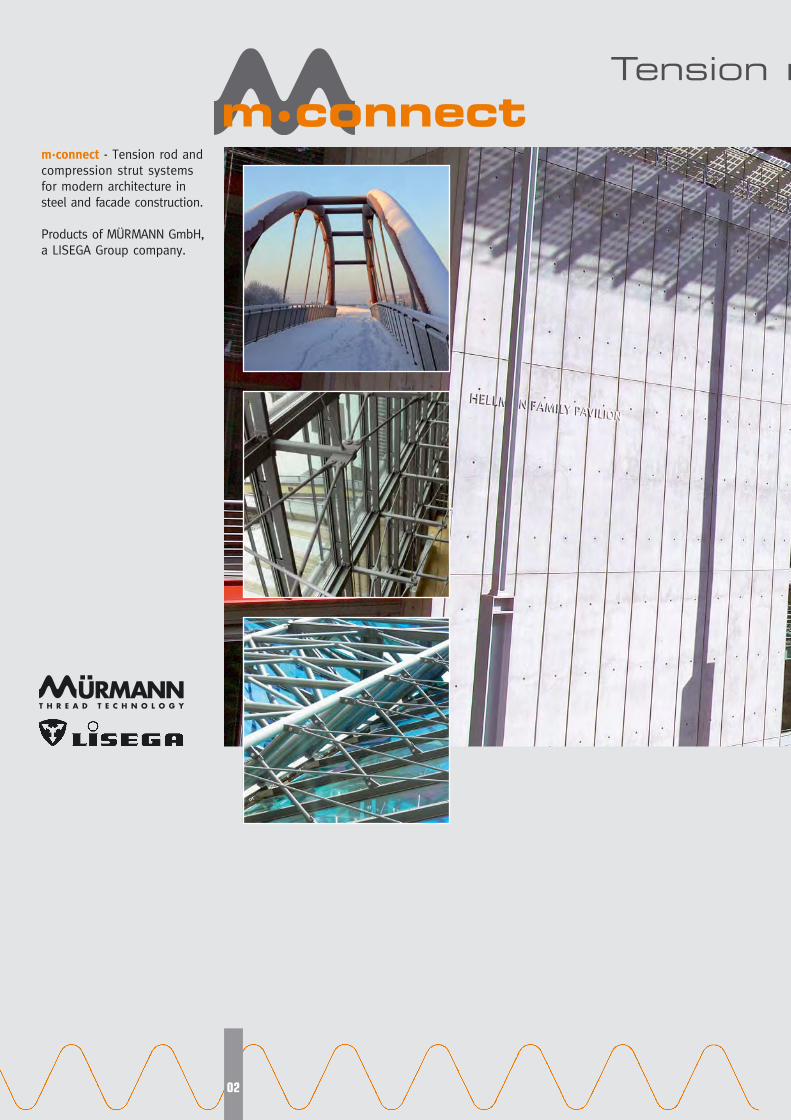
m·connect - Tension rod and
compression strut systems
for modern architecture in
steel and facade construction.
Products of MÜRMANN GmbH,
a LISEGA Group company.
Tension r
Mconnect-folder-a4-eng.qxp 17.02.2010 15:51 Uhr Seite 3
03
rod and compression strut systems
Contents
Construction elements formodern building technology 4
Elegant designs of lightweight construction 5
Practical construction elements for statics 6
Multiple applications 7
System elements8
Compression strut systems12
Connection plates and Structural attachments 14
Further practical components for steel construction 19
Functionality and Safety20
Rational application via modular system 21
CONNCADDesign and Engineering 23
Code numbers for clear identification 24
Special benefits for users 25
Installation instructions27
Mconnect-folder-a4-eng.qxp 17.02.2010 15:51 Uhr Seite 4

Modern architecture
The current trend in modern
architecture is, by the skilful
use of steel and glass, to
present large-scale buildings
as airy, futuristic constructions
soaring skywards.
Outstanding features of this
style of building are roofs that
seemingly float on air, with
a filigree supporting frame-
work and skilfully suspended
facades.
The availability of special,
easily integrated fastening and
support elements is a pre-
requisite for the optimum
implementation of this form
of construction. The special
tension rod and compression
strut systems, as integral ele-
ments in the building design,
must guarantee maximum
functionality and safety. At
the same time they must
blend into the whole con-
struction as clearly visible
design elements with aesthe-
tic appeal.
mm··ccoonnnneecctt product program
The product range of m·con-nect tension rod and com-
pression strut systems was
specially developed for the
smooth fulfilment of these
tasks.
The products meet the tough-
est demands and, due to their
wide-ranging applicability, are
of great practical benefit to
• architects, • construction engineers • construction companies
Tension rod and compressionstrut systems
The m·connect tension rod
systems are the ideal compo-
nents to distribute tension for-
ces in an economical and,
at the same time, elegant
manner. They are suited to
all types of suspension and
anchoring. Connection plates
(circular disks) and connecting
lugs provide optimum additio-
nal features.
The m·connect compression
strut systems are able to bear
tension forces, but are also
specially designed to take up
and distribute compression
forces. They are ideally suited
to act as stabilizing elements
and supports, suspension
components on simultaneous
compression loads and com-
pression struts in frame con-
struction.
By combining compression
strut and tension rod systems,
additional construction poss-
ibilities are available.
Construction elements formodern building technology
04
Mconnect-folder-a4-eng.qxp 17.02.2010 15:51 Uhr Seite 5
05
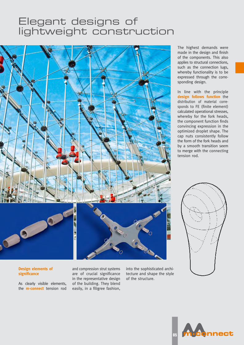
Design elements of significance
As clearly visible elements,
the m·connect tension rod
and compression strut systems
are of crucial significance
in the representative design
of the building. They blend
easily, in a filigree fashion,
into the sophisticated archi-
tecture and shape the style
of the structure.
Elegant designs of lightweight construction
The highest demands were
made in the design and finish
of the components. This also
applies to structural connections,
such as the connection lugs,
whereby functionality is to be
expressed through the corre-
sponding design.
In line with the principle
design follows function the
distribution of material corre-
sponds to FE (finite element)
calculated operational stresses,
whereby for the fork heads,
the component function finds
convincing expression in the
optimized droplet shape. The
cap nuts consistently follow
the form of the fork heads and
by a smooth transition seem
to merge with the connecting
tension rod.
Mconnect-folder-a4-eng.qxp 17.02.2010 15:51 Uhr Seite 6

Practical construction elements for statics
06
Suspension elements
Rear fastenings / struts /trusses / stays / bracing
Under-bracing
Cross stays / diagonal bracing
Prop supports
The m·connect construction
elements are designed strictly
according to the application
demands. In this way they
offer an economical and at
the same time attractive
solution to a wide range of
tasks in the field of construction.
As the distribution of materi-
al corresponds to the loads
imposed, the high-tensile
materials are exploited to
the optimum level.
This permits lightweight cons-
truction at maximum loading
capacity.
The modular system and
corresponding enginering soft-
ware further facilitate imple-
mentation and speed up the
design and construction cycle.
Mconnect-folder-a4-eng.qxp 17.02.2010 15:51 Uhr Seite 7
07
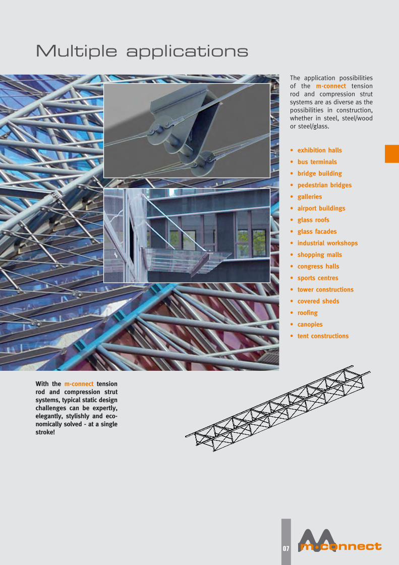
The application possibilities
of the m·connect tension
rod and compression strut
systems are as diverse as the
possibilities in construction,
whether in steel, steel/wood
or steel/glass.
• exhibition halls
• bus terminals
• bridge building
• pedestrian bridges
• galleries
• airport buildings
• glass roofs
• glass facades
• industrial workshops
• shopping malls
• congress halls
• sports centres
• tower constructions
• covered sheds
• roofing
• canopies
• tent constructions
Multiple applications
With the m·connect tensionrod and compression strutsystems, typical static designchallenges can be expertly,elegantly, stylishly and eco-nomically solved - at a singlestroke!
Mconnect-folder-a4-eng.qxp 17.02.2010 15:51 Uhr Seite 8
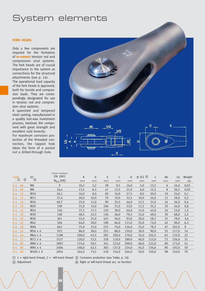
FORK HEADS
Only a few components are
required for the formation
of m·connect tension rod and
compression strut systems.
The fork heads are of crucial
importance in the system as
connections for the structural
attachments (see p. 14).
The operational load capacity
of the fork heads is approved,
both for tensile and compres-
sion loads. They are corres-
pondingly designated for use
in tension rod and compres-
sion strut systems.
A quenched and tempered
steel casting, manufactured in
a quality lost-wax investment
process, bestows the compo-
nent with great strength and
excellent cold tenecity.
For maximum corrosion pro-
tection of the threaded con-
nection, the tapped hole
takes the form of a pocket
not a drilled-through hole.
System elements
08
Type
6-4 . 06 .
6-4 . 08 .
6-4 . 10 .
6-4 . 12 .
6-4 . 16 .
6-4 . 20 .
6-4 . 24 .
6-4 . 30 .
6-4 . 36 .
6-4 . 42 .
6-4 . 48 .
6-4 . 56 .
6-4 . 64 .
6-4 . 72 .
6-4 . 80 .
6-4 . 90 .
6-4 . 00 .
d2
M6
M8
M10
M12
M16
M20
M24
M30
M36
M42
M48
M56 x 4
M64 x 4
M72 x 4
M80 x 4
M90 x 4
M100 x 4
Tension resistance
EN 1993
NR,d [kN]
9
16,4
26,1
37,4
69,7
109
156
248
361
504
662
933
1198
1527
1893
2406
2954
A[mm]
10,2
13,5
16,0
20,0
25,0
31,0
37,5
48,5
55,0
64,0
75,0
86,0
100,0
120,0
133,0
148,0
164,0
b[mm]
5,2
6,5
8,0
10,0
12,0
14,0
17,5
22,5
25,0
28,0
33,0
38,0
43,5
53,5
58,5
63,5
73,5
E[mm]
38
47
60
70
90
106
120
136
163
198
215
251
285
318
341
383
418
C[mm]
9,5
12,5
16,0
19,0
25,5
31,0
38,0
46,0
56,0
66,0
74,0
88,0
100,0
110,0
123,0
137,0
154,0
D[mm]
16,0
21,0
27,5
32,5
44,0
53,0
64,0
79,5
93,0
111,0
126,0
150,0
170,0
189,0
209,0
234,0
264,0
� V/2[mm]
5,0
6,0
8,0
10,0
12,5
12,5
15,0
15,0
20,0
25,0
25,0
30,0
35,0
40,0
40,0
45,0
50,0
x[mm]
12,5
15,5
20,0
24,0
31,0
35,5
42,0
49,0
58,5
72,0
78,5
90,0
102,5
115,0
122,0
136,0
150,0
db[mm]
6
8
10
12
16
20
24
30
35
42
47
55
63
72
80
90
98
Lb[mm]
16,0
20,5
24,0
29,0
36,0
44,0
53,0
68,0
78,0
90,0
102,0
117,0
133,0
156,0
173,0
192,0
210,0
Weight[kg]
0,02
0,05
0,1
0,2
0,4
0,8
1,2
2,2
3,6
6,3
9
14
22
31
41
59
79
� � ��
� 1 = right-hand thread, 2 = left-hand thread � Corrosion protection (see Table, p. 24)
� Adjustment � Right or left-hand thread acc. to function
Mconnect-folder-a4-eng.qxp 17.02.2010 15:51 Uhr Seite 9

09
Type
6-3106 .
6-3108 .
6-3110 .
6-3112 .
6-3116 .
6-3120 .
6-3124 .
6-3130 .
6-3136 .
6-3142 .
6-3148 .
6-3156 .
6-3164 .
6-3172 .
6-3180 .
6-3190 .
6-3100 .
d2 �
M6
M8
M10
M12
M16
M20
M24
M30
M36
M42
M48
M56 x 4
M64 x 4
M72 x 4
M80 x 4
M90 x 4
M100 x 4
L1[mm]
21
26
33
40
52
58
69
79
96
118
127
148
169
191
202
226
250
SW[mm]
5
7
9
10
14
18
22
28
32
38
41
50
60
65
75
85
95
Weight
1000mm
[kg]
0,2
0,4
0,6
0,9
1,6
2,5
3,5
5,5
8
11
14
19
25
32
40
50
62
TENSION RODS
The MÜRMANN plant can look
back on more than 40 successful
years of experience in the
manufacture of threaded rods
and studs. The threads can be
produced by cutting (CNC or
cutter head), rolling or spinn-
ing process. The tension rods
are equipped with left-hand /
right-hand threads for length
adjustment and with flat faces
on both sides. Individual rod
lengths of up to 12 m can be
supplied as standard. The
high-strength fine-grained
structural steel S460N is the
standard component material.
Other materials, including a
range of stainless steel can
also be supplied.
Cutting Rolling Spinning
� Left-hand thread on one side, right-hand thread on the other
� Material / corrosion protection (see Table, p.24)
�
Mconnect-folder-a4-eng.qxp 17.02.2010 15:51 Uhr Seite 10
10
Type
6-4 . 06 .
6-4 . 08 .
6-4 . 10 .
6-4 . 12 .
6-4 . 16 .
6-4 . 20 .
6-4 . 24 .
6-4 . 30 .
6-4 . 36 .
6-4 . 42 .
6-4 . 48 .
6-4 . 56 .
6-4 . 64 .
6-4 . 72 .
6-4 . 80 .
6-4 . 90 .
6-4 . 00 .
d2
M6
M8
M10
M12
M16
M20
M24
M30
M36
M42
M48
M56 x 4
M64 x 4
M72 x 4
M80 x 4
M90 x 4
M100 x 4
L
[mm]
16,5
20,0
25,5
31,0
39,5
42,5
51,0
55,5
57,5
71,0
73,5
88,0
101,5
116,0
120,0
135,0
150,0
d
[mm]
9,0
11,5
14,5
17,5
23,5
29,0
35,0
44,0
52,5
61,5
70,5
82,5
94,5
106,0
118,0
133,0
147,5
d4
[mm]
2,5
2,5
2,5
2,5
2,5
2,5
4,0
4,0
4,0
6,0
6,0
6,0
8,0
8,0
8,0
8,0
8,0
Weight
[kg]
0,004
0,007
0,013
0,024
0,06
0,10
0,16
0,30
0,45
0,70
1,00
1,60
2,40
3,40
4,40
6,30
8,50
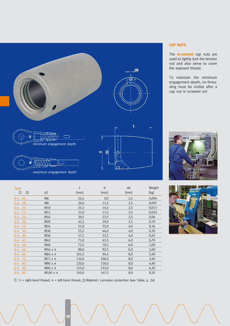
CAP NUTS
The m·connect cap nuts are
used to lightly lock the tension
rod and also serve to cover
the exposed thread.
To maintain the minimum
engagement depth, no threa-
ding must be visible after a
cap nut is screwed on!
minimum engagement depth
maximum engagement depth
� �
� 3 = right-hand thread, 4 = left-hand thread, � Material / corrosion protection (see Table, p. 24)
Mconnect-folder-a4-eng.qxp 17.02.2010 15:51 Uhr Seite 11

11
CONNECTING SLEEVES
The m·connect sleeves are
used as connecting parts
between the tension rods if
the system length, e.g. above
12 m, is to be extended.
Through standardised design
with left-hand/right-hand threads,
they function as a turnbuckle
at the same time.
CONNECTING SLEEVES WITH LUGS
The connecting sleeves can be
fitted with suspension lugs
for load-bearing in horizontally
arranged tension rod systems
(underbracing).
Type
6-4506 .
6-4508 .
6-4510 .
6-4512 .
6-4516 .
6-4520 .
6-4524 .
6-4530 .
6-4536 .
6-4542 .
6-4548 .
6-4556 .
6-4564 .
6-4572 .
6-4580 .
6-4590 .
6-4500 .
d2 �
M6
M8
M10
M12
M16
M20
M24
M30
M36
M42
M48
M56 x 4
M64 x 4
M72 x 4
M80 x 4
M90 x 4
M100 x 4
� left-hand on one side, right-hand on the other � Corrosion protection (see Table, p. 24)
The values d2, L, SW, V, X and Ød are identical for both types.
L
[mm]
35
43
56
68
87
96
114
128
157
194
207
240
275
310
324
362
400
ød
[mm]
11,5
14,5
18,0
20,0
27,0
33,0
40,0
51,0
61,0
72,0
83,0
94,0
111,0
122,0
139,0
155,0
172,0
SW
[mm]
10
13
16
18
24
30
36
46
55
65
75
85
100
110
125
140
155
�V
[mm]
10
12
16
20
25
25
30
30
40
50
50
60
70
80
80
90
100
X
[mm]
12,5
15,5
20,0
24,0
31,0
35,5
42,0
49,0
58,5
72,0
78,5
90,0
102,5
115,0
122,0
136,0
150,0
Weight
[kg]
0,02
0,03
0,06
0,10
0,20
0,40
0,60
1,10
2,00
3,30
4,60
6,80
11,00
14,50
20,00
28,00
37,00
Type
6-4606 .
6-4608 .
6-4610 .
6-4612 .
6-4616 .
6-4620 .
6-4624 .
6-4630 .
6-4636 .
6-4642 .
6-4648 .
6-4656 .
6-4664 .
6-4672 .
6-4680 .
6-4690 .
6-4600 .
ød3
[mm]
6,3
6,3
6,3
6,3
8,4
8,4
10,5
10,5
10,5
12,5
12,5
16,5
16,5
16,5
20,5
20,5
20,5
E
[mm]
22
23
25
26
33
36
43
48
53
62
67
78
87
92
108
116
125
t
[mm]
4
4
4
4
5
5
6
6
6
8
8
10
10
10
12
12
12
C
[mm]
11,5
11,5
11,5
11,5
15,5
15,5
19,5
19,5
19,5
22,5
22,5
31,0
31,0
31,0
39,0
39,0
39,0
Weight
[kg]
0,04
0,05
0,08
0,12
0,25
0,45
0,70
1,20
2,10
3,40
4,70
7,00
11,20
14,80
20,50
28,50
38,50
� �
Mconnect-folder-a4-eng.qxp 17.02.2010 15:51 Uhr Seite 12
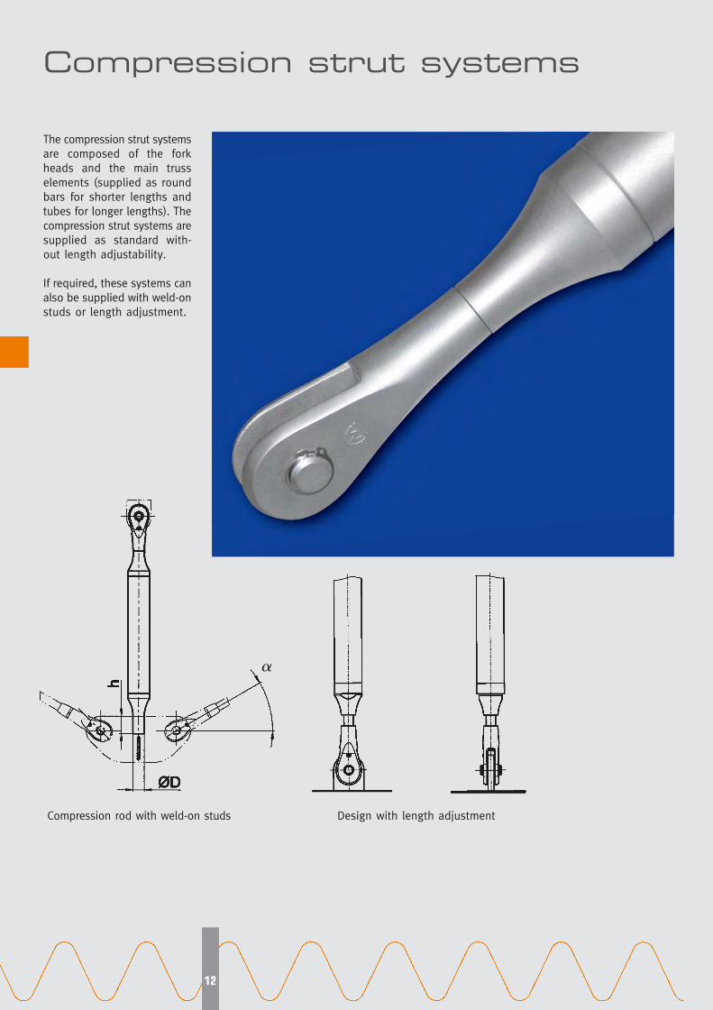
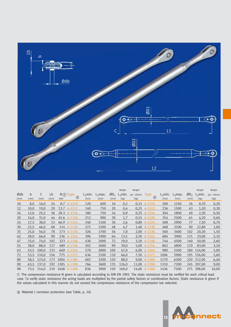
The compression strut systems
are composed of the fork
heads and the main truss
elements (supplied as round
bars for shorter lengths and
tubes for longer lengths). The
compression strut systems are
supplied as standard with-
out length adjustability.
If required, these systems can
also be supplied with weld-on
studs or length adjustment.
Compression strut systems
Design with length adjustmentCompression rod with weld-on studs
�
12
Mconnect-folder-a4-eng.qxp 17.02.2010 15:51 Uhr Seite 13
13
Type
6-1110 .
6-1112 .
6-1116 .
6-1120 .
6-1124 .
6-1130 .
6-1136 .
6-1142 .
6-1148 .
6-1156 .
6-1164 .
6-1172 .
6-1180 .
6-1190 .
6-1100 .
Ødb[mm]
10
12
16
20
24
30
35
42
47
55
63
72
80
90
98
b[mm]
8,0
10,0
12,0
14,0
17,5
22,5
25,0
28,0
33,0
38,0
43,5
53,5
58,5
63,5
73,5
C[mm]
16,0
19,0
25,5
31,0
38,0
46,0
56,0
66,0
74,0
88,0
100,0
110,0
123,0
137,0
154,0
Lb[mm]
24
29
36
44
53
68
78
90
102
117
133
156
173
192
210
N[kN]
8.7
13.7
28.3
45.6
66.9
114
173
236
323
489
669
775
1004
1305
1648
L1min.[mm]
120
140
180
212
240
272
326
396
430
502
570
636
682
766
836
L1max.[mm]
600
750
750
900
1100
1500
1700
1900
2000
2600
2800
3100
3200
3600
3900
ØD1[mm]
16
20
24
30
36
48
56
64
72
90
100
110
120
135
150
Weight
L1min.[kg]
0,2
0,4
0,9
1,7
2,6
4,7
7,8
13,5
19,0
30,0
47,0
66,0
88,0
126,0
169,0
Weight
per 100mm
[kg]
0,15
0,25
0,35
0,55
0,80
1,40
2,00
2,50
3,20
5,00
6,00
7,50
9,00
11,00
14,00
Type
6-1310 .
6-1312 .
6-1316 .
6-1320 .
6-1324 .
6-1330 .
6-1336 .
6-1342 .
6-1348 .
6-1356 .
6-1364 .
6-1372 .
6-1380 .
6-1390 .
6-1300 .
L2min.[mm]
200
236
304
354
408
468
560
684
744
862
980
1096
1170
1310
1436
L2max.[mm]
1250
1500
1800
2500
2900
3100
3400
3900
4500
4800
5500
5900
6200
7200
7500
ØD2[mm]
34
43
49
61
77
90
102
115
140
170
180
195
220
245
275
Weight
L2min.[kg]
0,70
1,20
2,30
4,20
7,50
12,80
20,30
33,00
50,00
83,00
114,00
156,00
212,00
297,00
398,00
Weight
per 100mm
[kg]
0,20
0,30
0,50
0,60
0,70
1,00
1,50
2,10
2,60
3,20
5,00
5,60
6,40
9,00
10,00
� The compression resistance N given is calculated according to DIN EN 1993. The static resistance must be verified for each critical load
case. To verify static resistance the acting loads are multiplied by the partial safety factors or combination factors. Static resistance is given if
the values calculated in this manner do not exceed the compression resistance of the compression bar selected.
� Material / corrosion protection (see Table, p. 24)
�� �
Lb
b
Ødb
ØD1
ØD2
L2
L1C
Mconnect-folder-a4-eng.qxp 17.02.2010 15:52 Uhr Seite 14

CONNECTION PLATES
The m·connect connecting
plates are required in frame
constructions as central junct-
ion points. In standard designs
three or four tension rods can
be attached.
To guarantee a secure load
distribution, only m·connectconnecting plates with the
material quality and dimensions
corresponding to calculations
should be implemented.
The direction of forces always
passes through the junction
point – an angle displacement
of 5 % is permissible.
For selection according to a
particular design the basic
shapes, e.g. rectangular or
circular, are offered as stan-
dard. Variants can however
be supplied.
14
Connection plates and Structural attachments
Mconnect-folder-a4-eng.qxp 17.02.2010 15:52 Uhr Seite 15
15
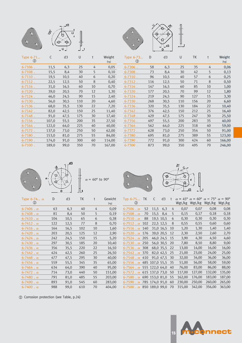
Type 6-74... �
6-7406 . �6-7408 . �6-7410 . �6-7412 . �6-7416 . �6-7420 . �6-7424 . �6-7430 . �6-7436 . �6-7442 . �6-7448 . �6-7456 . �6-7464 . �6-7472 . �6-7480 . �6-7490 . �6-7400 . �
D
63
81
104
122
164
203
242
297
356
424
477
559
634
714
791
893
988
Gewicht[kg]
0,09
0,19
0,38
0,70
1,60
2,90
5,20
10,40
16,50
26,50
40,00
65,00
95,00
151,00
203,00
283,00
404,00
d3
6,3
8,4
10,5
12,5
16,5
20,5
24,5
30,5
35,5
42,5
47,5
55,5
64,0
73,0
81,0
91,0
99,0
TK
40
50
65
77
102
125
150
185
220
260
295
345
390
440
485
545
610
t
4
5
6
8
10
12
15
20
22
25
30
35
40
50
55
60
70
Typ 6-75...
6-7506 . �6-7508 . �6-7510 . �6-7512 . �6-7516 . �6-7520 . �6-7524 . �6-7530 . �6-7536 . �6-7542 . �6-7548 . �6-7556 . �6-7564 . �6-7572 . �6-7580 . �6-7590 . �6-7500 . �
TK
52
70
88
102
140
176
205
250
308
370
410
485
555
615
690
785
850
C
11,5
15,5
19,5
22,5
31,0
39,0
46,0
56,0
68,0
82,0
91,0
107,0
122,0
137,0
153,0
174,0
189,0
d3
6,3
8,4
10,5
12,5
16,5
20,5
24,5
30,5
35,5
42,5
47,5
55,5
64,0
73,0
81,0
91,0
99,0
t
4
5
6
8
10
12
15
20
22
25
30
35
40
50
55
60
70
Type 6-73...
6-7306 .
6-7308 .
6-7310 .
6-7312 .
6-7316 .
6-7320 .
6-7324 .
6-7330 .
6-7336 .
6-7342 .
6-7348 .
6-7356 .
6-7364 .
6-7372 .
6-7380 .
6-7390 .
6-7300 .
D
58
73
96
116
147
177
219
268
320
376
429
497
562
628
695
772
873
Weight[kg]
0,06
0,13
0,25
0,50
1,00
1,80
3,30
6,60
10,40
16,40
25,50
40,00
59,00
91,00
123,00
166,00
246,00
d3
6,3
8,4
10,5
12,5
16,5
20,5
24,5
30,5
35,5
42,5
47,5
55,5
64,0
73,0
81,0
91,0
99,0
U
25
30
40
50
60
70
90
110
130
150
175
200
225
250
275
300
350
TK
35
42
57
71
85
99
127
156
184
212
247
283
318
354
389
424
495
t
4
5
6
8
10
12
15
20
22
25
30
35
40
50
55
60
70
Type 6-71...
6-7106 .
6-7108 .
6-7110 .
6-7112 .
6-7116 .
6-7120 .
6-7124 .
6-7130 .
6-7136 .
6-7142 .
6-7148 .
6-7156 .
6-7164 .
6-7172 .
6-7180 .
6-7190 .
6-7100 .
Weight[kg]
0,05
0,10
0,20
0,40
0,70
1,30
2,40
4,60
7,20
11,40
17,40
27,50
40,00
62,00
84,00
114,00
167,00
C
11,5
15,5
19,5
22,5
31,0
39,0
46,0
56,0
68,0
82,0
91,0
107,0
122,0
137,0
153,0
174,0
189,0
d3
6,3
8,4
10,5
12,5
16,5
20,5
24,5
30,5
35,5
42,5
47,5
55,5
64,0
73,0
81,0
91,0
99,0
U
25
30
40
50
60
70
90
110
130
150
175
200
225
250
275
300
350
t
4
5
6
8
10
12
15
20
22
25
30
35
40
50
55
60
70
� = 45°Wgt./kg
0,07
0,15
0,30
0,55
1,20
2,30
3,90
7,80
13,00
21,00
32,00
51,00
76,00
117,00
162,00
230,00
315,00
� = 90°Wgt./kg
0,08
0,18
0,30
0,60
1,40
2,70
4,60
9,00
16,00
25,00
36,00
59,00
88,00
135,00
187,00
265,00
363,00
� = 60°Wgt./kg
0,07
0,17
0,30
0,55
1,30
2,50
4,30
8,50
14,00
23,00
34,00
56,00
83,00
127,00
176,00
250,00
342,00
� = 75°Wgt./kg
0,08
0,18
0,30
0,60
1,40
2,60
4,50
8,80
16,00
24,00
36,00
58,00
86,00
132,00
183,00
260,00
356,00
� Corrosion protection (see Table, p.24)
�
�
�
�
� = 60° to 90°
Mconnect-folder-a4-eng.qxp 17.02.2010 15:52 Uhr Seite 16
16
�
06
08
10
12
16
20
24
30
36
42
48
56
64
72
80
90
00
A
19
25
32
38
52
65
76
92
114
137
151
179
204
228
255
290
317
Weight[kg]
0,02
0,04
0,06
0,10
0,25
0,45
0,75
1,40
2,40
3,90
5,80
9,50
14,00
21,00
29,00
40,60
57,50
E
20
22
25
30
39
46
53
63
77
91
102
122
137
147
164
183
208
a
3,0
3,0
3,0
3,0
4,0
5,0
6,0
7,5
9,0
10,5
12,5
14,5
16,5
18,0
20,0
22,5
25,5
Type 6 - 60 . . . -10
� = 10°
� �
A
20
27
34
39
54
68
80
97
119
144
159
187
214
239
267
304
332
Weight[kg]
0,02
0,04
0,06
0,10
0,25
0,45
0,75
1,50
2,50
4,00
5,90
9,70
14,40
21,50
30,00
42,00
59,00
E
21
23
27
32
40
48
55
66
81
96
106
128
144
154
172
192
218
a
3,0
3,0
3,0
3,0
4,0
5,0
6,0
7,5
9,0
10,0
12,0
14,0
16,0
17,5
19,5
21,5
24,5
Type 6 - 60 . . . -20
� = 20°
A
21
29
37
43
59
74
87
105
129
156
172
203
232
260
290
330
360
Weight[kg]
0,02
0,04
0,07
0,12
0,25
0,50
0,80
1,60
2,60
4,20
6,20
10,30
15,20
22,80
31,50
44,00
63,00
E
23
25
29
35
44
52
60
72
88
104
115
139
156
167
187
208
237
a
3,0
3,0
3,0
3,0
3,5
4,5
5,5
7,0
8,0
9,5
11,0
13,0
15,0
16,0
18,0
20,0
22,5
Type 6 - 60 . . . -30
� = 30°
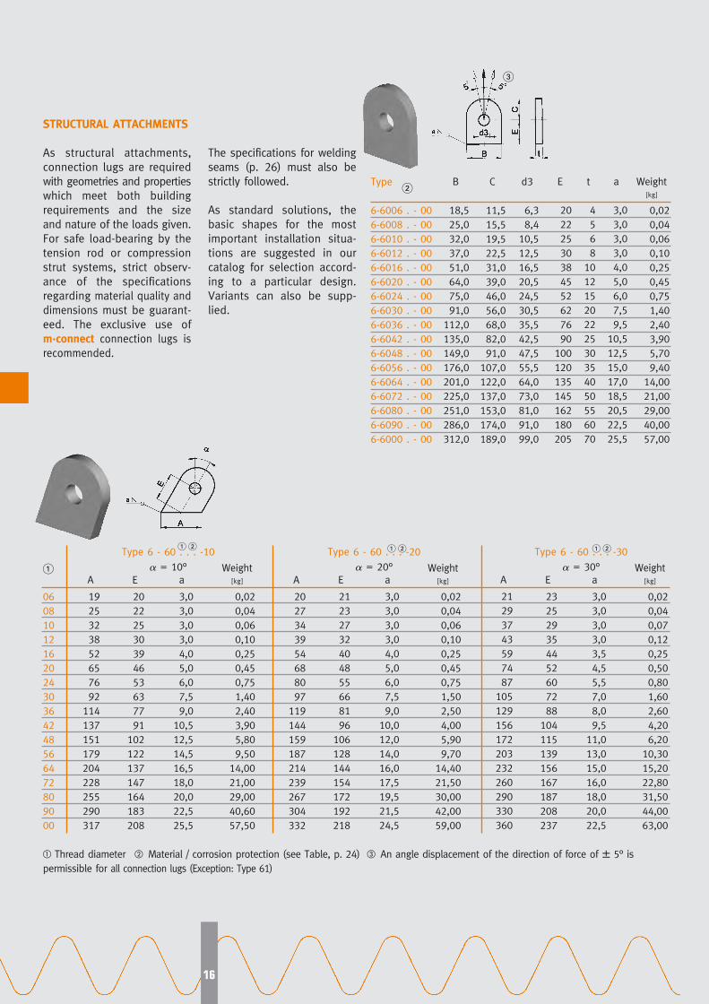
STRUCTURAL ATTACHMENTS
As structural attachments,
connection lugs are required
with geometries and properties
which meet both building
requirements and the size
and nature of the loads given.
For safe load-bearing by the
tension rod or compression
strut systems, strict observ-
ance of the specifications
regarding material quality and
dimensions must be guarant-
eed. The exclusive use of
m·connect connection lugs is
recommended.
The specifications for welding
seams (p. 26) must also be
strictly followed.
As standard solutions, the
basic shapes for the most
important installation situa-
tions are suggested in our
catalog for selection accord-
ing to a particular design.
Variants can also be supp-
lied.
Type
6-6006 . - 00
6-6008 . - 00
6-6010 . - 00
6-6012 . - 00
6-6016 . - 00
6-6020 . - 00
6-6024 . - 00
6-6030 . - 00
6-6036 . - 00
6-6042 . - 00
6-6048 . - 00
6-6056 . - 00
6-6064 . - 00
6-6072 . - 00
6-6080 . - 00
6-6090 . - 00
6-6000 . - 00
B
18,5
25,0
32,0
37,0
51,0
64,0
75,0
91,0
112,0
135,0
149,0
176,0
201,0
225,0
251,0
286,0
312,0
Weight[kg]
0,02
0,04
0,06
0,10
0,25
0,45
0,75
1,40
2,40
3,90
5,70
9,40
14,00
21,00
29,00
40,00
57,00
C
11,5
15,5
19,5
22,5
31,0
39,0
46,0
56,0
68,0
82,0
91,0
107,0
122,0
137,0
153,0
174,0
189,0
d3
6,3
8,4
10,5
12,5
16,5
20,5
24,5
30,5
35,5
42,5
47,5
55,5
64,0
73,0
81,0
91,0
99,0
E
20
22
25
30
38
45
52
62
76
90
100
120
135
145
162
180
205
t
4
5
6
8
10
12
15
20
22
25
30
35
40
50
55
60
70
a
3,0
3,0
3,0
3,0
4,0
5,0
6,0
7,5
9,5
10,5
12,5
15,0
17,0
18,5
20,5
22,5
25,5
�
�
� �� �
� Thread diameter � Material / corrosion protection (see Table, p. 24) � An angle displacement of the direction of force of � 5° is
permissible for all connection lugs (Exception: Type 61)
Mconnect-folder-a4-eng.qxp 17.02.2010 15:52 Uhr Seite 17
17
�
06
08
10
12
16
20
24
30
36
42
48
56
64
72
80
90
00
A1
9
13
17
21
29
36
43
52
64
77
85
100
114
128
143
164
178
Weight[kg]
0,02
0,04
0,07
0,12
0,30
0,50
0,90
1,70
2,80
4,60
6,80
11,20
16,50
25,00
34,00
47,00
68,00
E
26
29
33
39
50
59
68
81
99
117
131
157
176
189
211
235
268
a
3,0
3,0
3,0
3,0
4,0
4,5
5,5
7,0
8,5
9,5
11,5
13,5
15,0
17,0
18,5
20,5
23,0
Type 6 - 60 . . . -40
� = 40°
A2
16
20
24
28
37
47
55
67
83
99
110
130
148
165
185
210
230
A1
9
13
18
22
31
40
46
56
69
83
91
107
123
139
155
177
192
Weight[kg]
0,02
0,04
0,08
0,15
0,30
0,60
0,90
1,80
3,00
4,80
7,20
11,80
17,50
26,00
36,00
50,00
72,00
E
28
31
35
42
54
64
74
88
107
127
141
170
191
205
229
255
290
a
3,0
3,0
3,0
3,0
3,5
4,5
5,0
6,5
8,0
9,0
10,5
12,5
14,0
15,5
17,0
19,0
21,5
Type 6 - 60 . . . -45
� = 45°
A2
17
22
27
30
41
51
60
73
90
107
120
141
161
180
200
228
250
A1
11
18
25
30
44
57
66
80
99
119
131
154
177
198
222
253
275
Weight[kg]
0,03
0,06
0,10
0,20
0,40
0,70
1,20
2,30
3,80
6,20
9,20
15,20
22,30
33,50
46,00
64,00
92,00
E
40
44
50
60
76
90
104
124
152
180
200
240
270
290
324
360
410
a
3,0
3,0
3,0
3,0
3,0
3,0
3,5
4,5
5,5
6,5
7,5
9,0
10,0
11,0
12,0
13,5
15,0
Type 6 - 60 . . . -60
� = 60°
A2
26
32
39
44
58
71
84
102
125
151
167
198
225
252
280
319
349
A1
9
14
20
24
35
44
51
62
75
92
101
119
136
152
171
195
212
Weight[kg]
0,02
0,05
0,10
0,15
0,30
0,60
1,00
1,90
3,20
5,20
7,60
12,60
18,50
28,00
38,50
54,00
77,00
E
31
34
39
47
59
70
81
96
118
140
156
187
210
226
252
280
319
a
3,0
3,0
3,0
3,0
3,5
4,0
5,0
6,0
7,0
8,0
9,5
11,5
13,0
14,5
15,5
17,5
19,5
Type 6 - 60 . . . -50
� = 50°
A2
19
25
30
34
45
56
66
80
99
118
131
155
177
198
220
250
274
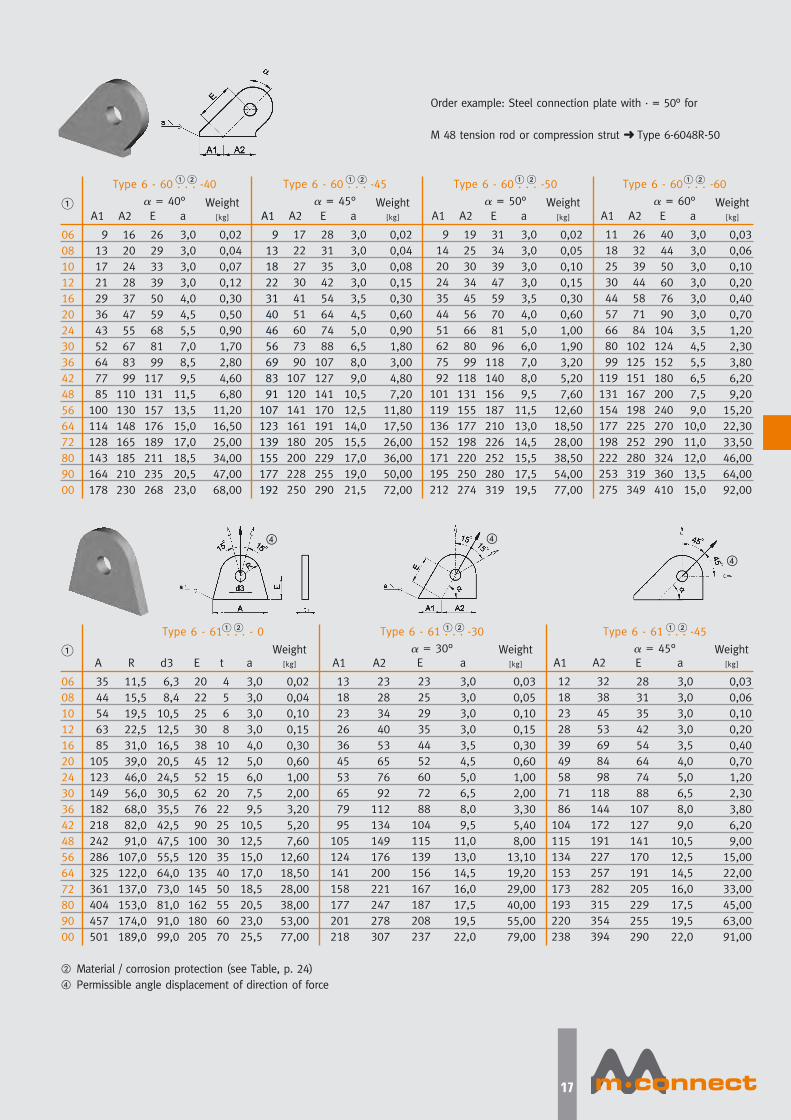
Order example: Steel connection plate with · = 50° for
M 48 tension rod or compression strut ➜ Type 6-6048R-50
�
06
08
10
12
16
20
24
30
36
42
48
56
64
72
80
90
00
A
35
44
54
63
85
105
123
149
182
218
242
286
325
361
404
457
501
Weight[kg]
0,02
0,04
0,10
0,15
0,30
0,60
1,00
2,00
3,20
5,20
7,60
12,60
18,50
28,00
38,00
53,00
77,00
R
11,5
15,5
19,5
22,5
31,0
39,0
46,0
56,0
68,0
82,0
91,0
107,0
122,0
137,0
153,0
174,0
189,0
t
4
5
6
8
10
12
15
20
22
25
30
35
40
50
55
60
70
Type 6 - 61 . . . - 0
A1
13
18
23
26
36
45
53
65
79
95
105
124
141
158
177
201
218
Weight[kg]
0,03
0,05
0,10
0,15
0,30
0,60
1,00
2,00
3,30
5,40
8,00
13,10
19,20
29,00
40,00
55,00
79,00
A2
23
28
34
40
53
65
76
92
112
134
149
176
200
221
247
278
307
a
3,0
3,0
3,0
3,0
3,5
4,5
5,0
6,5
8,0
9,5
11,0
13,0
14,5
16,0
17,5
19,5
22,0
Type 6 - 61 . . . -30
� = 30°
A1
12
18
23
28
39
49
58
71
86
104
115
134
153
173
193
220
238
Weight[kg]
0,03
0,06
0,10
0,20
0,40
0,70
1,20
2,30
3,80
6,20
9,00
15,00
22,00
33,00
45,00
63,00
91,00
E
28
31
35
42
54
64
74
88
107
127
141
170
191
205
229
255
290
a
3,0
3,0
3,0
3,0
3,5
4,0
5,0
6,5
8,0
9,0
10,5
12,5
14,5
16,0
17,5
19,5
22,0
Type 6 - 61 . . . -45
� = 45°
d3
6,3
8,4
10,5
12,5
16,5
20,5
24,5
30,5
35,5
42,5
47,5
55,5
64,0
73,0
81,0
91,0
99,0
E
20
22
25
30
38
45
52
62
76
90
100
120
135
145
162
180
205
a
3,0
3,0
3,0
3,0
4,0
5,0
6,0
7,5
9,5
10,5
12,5
15,0
17,0
18,5
20,5
23,0
25,5
E
23
25
29
35
44
52
60
72
88
104
115
139
156
167
187
208
237
A2
32
38
45
53
69
84
98
118
144
172
191
227
257
282
315
354
394
� Material / corrosion protection (see Table, p. 24)
� Permissible angle displacement of direction of force
� �
� � � � � �
� � � � � �
� �
�
Mconnect-folder-a4-eng.qxp 17.02.2010 15:52 Uhr Seite 18
18
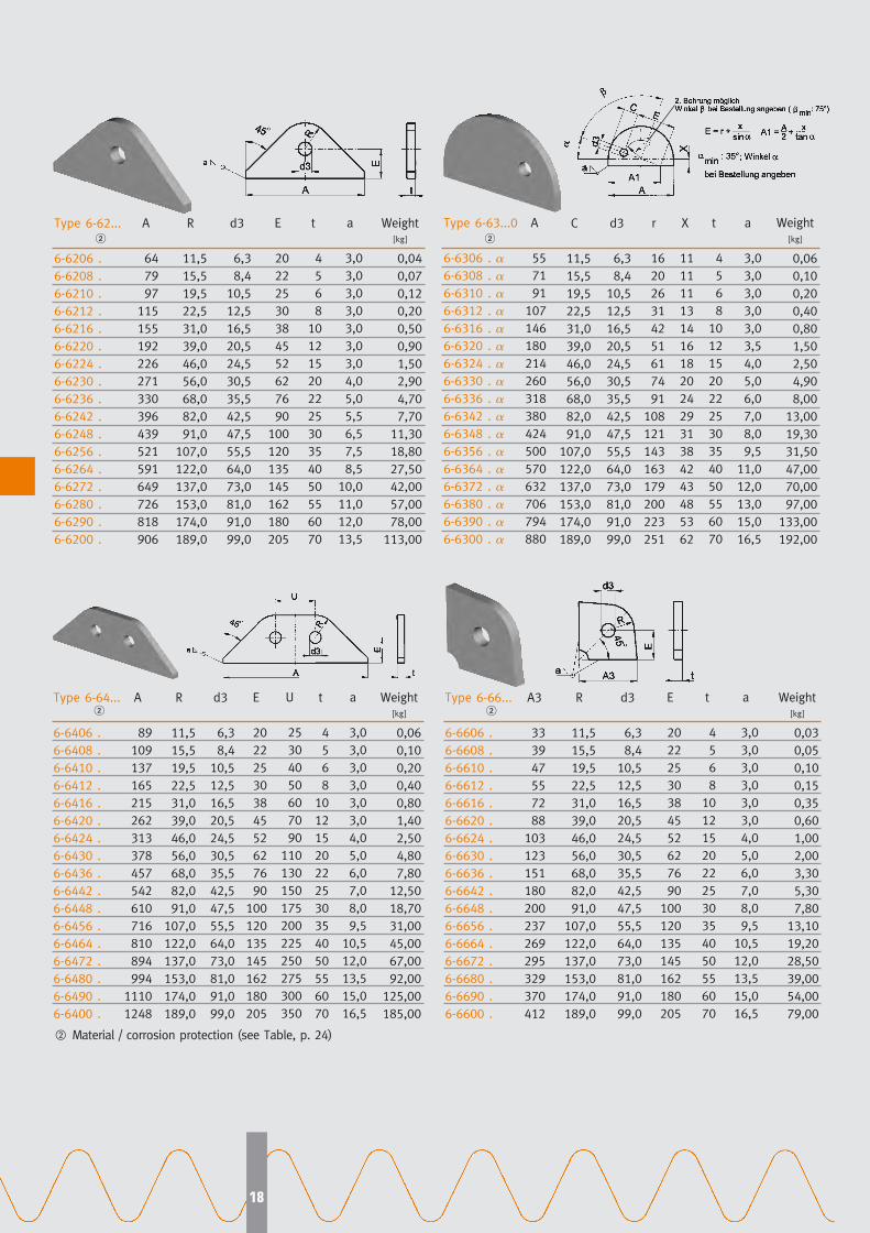
Type 6-64...
6-6406 .
6-6408 .
6-6410 .
6-6412 .
6-6416 .
6-6420 .
6-6424 .
6-6430 .
6-6436 .
6-6442 .
6-6448 .
6-6456 .
6-6464 .
6-6472 .
6-6480 .
6-6490 .
6-6400 .
A
89
109
137
165
215
262
313
378
457
542
610
716
810
894
994
1110
1248
Weight[kg]
0,06
0,10
0,20
0,40
0,80
1,40
2,50
4,80
7,80
12,50
18,70
31,00
45,00
67,00
92,00
125,00
185,00
R
11,5
15,5
19,5
22,5
31,0
39,0
46,0
56,0
68,0
82,0
91,0
107,0
122,0
137,0
153,0
174,0
189,0
d3
6,3
8,4
10,5
12,5
16,5
20,5
24,5
30,5
35,5
42,5
47,5
55,5
64,0
73,0
81,0
91,0
99,0
E
20
22
25
30
38
45
52
62
76
90
100
120
135
145
162
180
205
t
4
5
6
8
10
12
15
20
22
25
30
35
40
50
55
60
70
a
3,0
3,0
3,0
3,0
3,0
3,0
4,0
5,0
6,0
7,0
8,0
9,5
10,5
12,0
13,5
15,0
16,5
Type 6-66...
6-6606 .
6-6608 .
6-6610 .
6-6612 .
6-6616 .
6-6620 .
6-6624 .
6-6630 .
6-6636 .
6-6642 .
6-6648 .
6-6656 .
6-6664 .
6-6672 .
6-6680 .
6-6690 .
6-6600 .
A3
33
39
47
55
72
88
103
123
151
180
200
237
269
295
329
370
412
Weight[kg]
0,03
0,05
0,10
0,15
0,35
0,60
1,00
2,00
3,30
5,30
7,80
13,10
19,20
28,50
39,00
54,00
79,00
R
11,5
15,5
19,5
22,5
31,0
39,0
46,0
56,0
68,0
82,0
91,0
107,0
122,0
137,0
153,0
174,0
189,0
d3
6,3
8,4
10,5
12,5
16,5
20,5
24,5
30,5
35,5
42,5
47,5
55,5
64,0
73,0
81,0
91,0
99,0
E
20
22
25
30
38
45
52
62
76
90
100
120
135
145
162
180
205
t
4
5
6
8
10
12
15
20
22
25
30
35
40
50
55
60
70
a
3,0
3,0
3,0
3,0
3,0
3,0
4,0
5,0
6,0
7,0
8,0
9,5
10,5
12,0
13,5
15,0
16,5
U
25
30
40
50
60
70
90
110
130
150
175
200
225
250
275
300
350
Type 6-62...
6-6206 .
6-6208 .
6-6210 .
6-6212 .
6-6216 .
6-6220 .
6-6224 .
6-6230 .
6-6236 .
6-6242 .
6-6248 .
6-6256 .
6-6264 .
6-6272 .
6-6280 .
6-6290 .
6-6200 .
A
64
79
97
115
155
192
226
271
330
396
439
521
591
649
726
818
906
Weight[kg]
0,04
0,07
0,12
0,20
0,50
0,90
1,50
2,90
4,70
7,70
11,30
18,80
27,50
42,00
57,00
78,00
113,00
R
11,5
15,5
19,5
22,5
31,0
39,0
46,0
56,0
68,0
82,0
91,0
107,0
122,0
137,0
153,0
174,0
189,0
d3
6,3
8,4
10,5
12,5
16,5
20,5
24,5
30,5
35,5
42,5
47,5
55,5
64,0
73,0
81,0
91,0
99,0
E
20
22
25
30
38
45
52
62
76
90
100
120
135
145
162
180
205
t
4
5
6
8
10
12
15
20
22
25
30
35
40
50
55
60
70
a
3,0
3,0
3,0
3,0
3,0
3,0
3,0
4,0
5,0
5,5
6,5
7,5
8,5
10,0
11,0
12,0
13,5
Type 6-63...0
6-6306 . �6-6308 . �6-6310 . �6-6312 . �6-6316 . �6-6320 . �6-6324 . �6-6330 . �6-6336 . �6-6342 . �6-6348 . �6-6356 . �6-6364 . �6-6372 . �6-6380 . �6-6390 . �6-6300 . �
A
55
71
91
107
146
180
214
260
318
380
424
500
570
632
706
794
880
Weight[kg]
0,06
0,10
0,20
0,40
0,80
1,50
2,50
4,90
8,00
13,00
19,30
31,50
47,00
70,00
97,00
133,00
192,00
C
11,5
15,5
19,5
22,5
31,0
39,0
46,0
56,0
68,0
82,0
91,0
107,0
122,0
137,0
153,0
174,0
189,0
d3
6,3
8,4
10,5
12,5
16,5
20,5
24,5
30,5
35,5
42,5
47,5
55,5
64,0
73,0
81,0
91,0
99,0
r
16
20
26
31
42
51
61
74
91
108
121
143
163
179
200
223
251
X
11
11
11
13
14
16
18
20
24
29
31
38
42
43
48
53
62
a
3,0
3,0
3,0
3,0
3,0
3,5
4,0
5,0
6,0
7,0
8,0
9,5
11,0
12,0
13,0
15,0
16,5
t
4
5
6
8
10
12
15
20
22
25
30
35
40
50
55
60
70
� Material / corrosion protection (see Table, p. 24)
� �
��
Mconnect-folder-a4-eng.qxp 17.02.2010 15:52 Uhr Seite 19
19
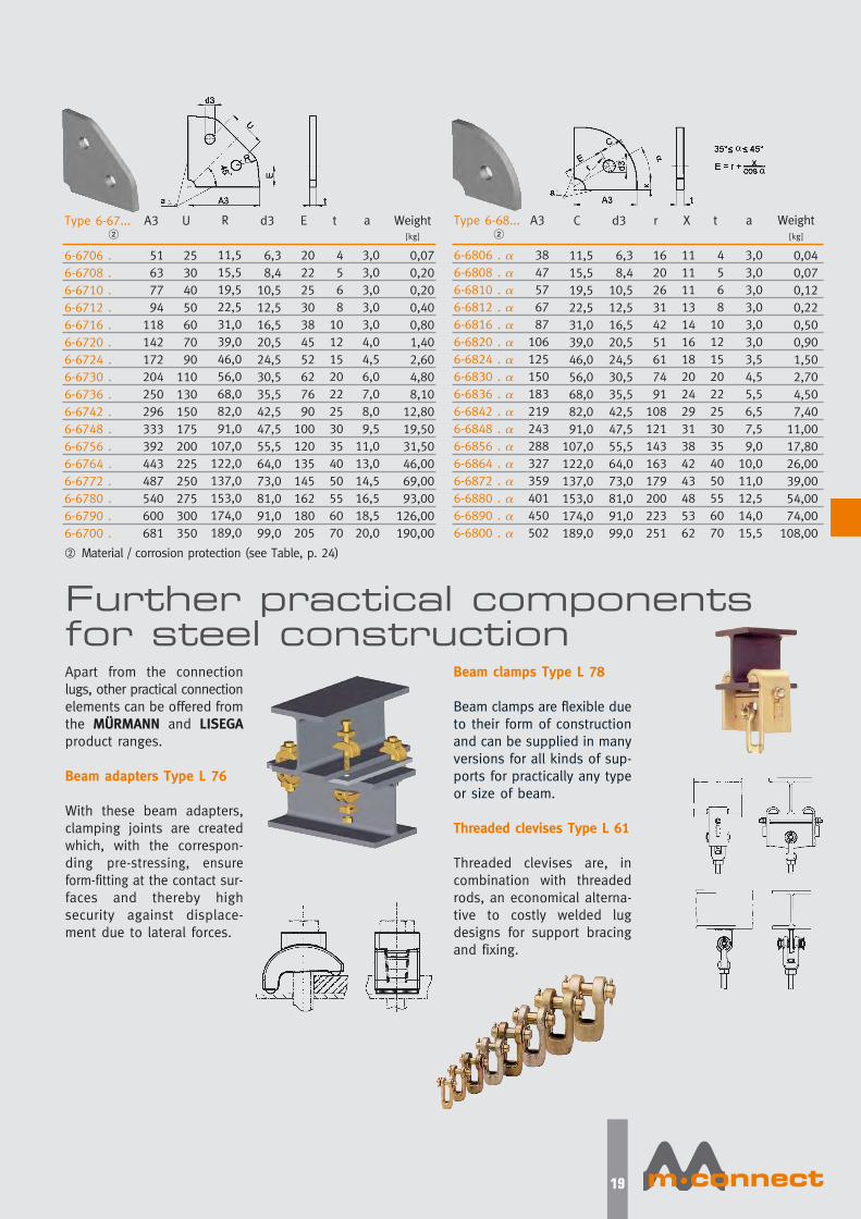
Type 6-67...
6-6706 .
6-6708 .
6-6710 .
6-6712 .
6-6716 .
6-6720 .
6-6724 .
6-6730 .
6-6736 .
6-6742 .
6-6748 .
6-6756 .
6-6764 .
6-6772 .
6-6780 .
6-6790 .
6-6700 .
A3
51
63
77
94
118
142
172
204
250
296
333
392
443
487
540
600
681
Weight[kg]
0,07
0,20
0,20
0,40
0,80
1,40
2,60
4,80
8,10
12,80
19,50
31,50
46,00
69,00
93,00
126,00
190,00
U
25
30
40
50
60
70
90
110
130
150
175
200
225
250
275
300
350
d3
6,3
8,4
10,5
12,5
16,5
20,5
24,5
30,5
35,5
42,5
47,5
55,5
64,0
73,0
81,0
91,0
99,0
E
20
22
25
30
38
45
52
62
76
90
100
120
135
145
162
180
205
t
4
5
6
8
10
12
15
20
22
25
30
35
40
50
55
60
70
a
3,0
3,0
3,0
3,0
3,0
4,0
4,5
6,0
7,0
8,0
9,5
11,0
13,0
14,5
16,5
18,5
20,0
Type 6-68...
6-6806 . �6-6808 . �6-6810 . �6-6812 . �6-6816 . �6-6820 . �6-6824 . �6-6830 . �6-6836 . �6-6842 . �6-6848 . �6-6856 . �6-6864 . �6-6872 . �6-6880 . �6-6890 . �6-6800 . �
A3
38
47
57
67
87
106
125
150
183
219
243
288
327
359
401
450
502
Weight[kg]
0,04
0,07
0,12
0,22
0,50
0,90
1,50
2,70
4,50
7,40
11,00
17,80
26,00
39,00
54,00
74,00
108,00
C
11,5
15,5
19,5
22,5
31,0
39,0
46,0
56,0
68,0
82,0
91,0
107,0
122,0
137,0
153,0
174,0
189,0
d3
6,3
8,4
10,5
12,5
16,5
20,5
24,5
30,5
35,5
42,5
47,5
55,5
64,0
73,0
81,0
91,0
99,0
r
16
20
26
31
42
51
61
74
91
108
121
143
163
179
200
223
251
X
11
11
11
13
14
16
18
20
24
29
31
38
42
43
48
53
62
a
3,0
3,0
3,0
3,0
3,0
3,0
3,5
4,5
5,5
6,5
7,5
9,0
10,0
11,0
12,5
14,0
15,5
t
4
5
6
8
10
12
15
20
22
25
30
35
40
50
55
60
70
R
11,5
15,5
19,5
22,5
31,0
39,0
46,0
56,0
68,0
82,0
91,0
107,0
122,0
137,0
153,0
174,0
189,0
Further practical componentsfor steel constructionApart from the connection
lugs, other practical connection
elements can be offered from
the MÜRMANN and LISEGAproduct ranges.
Beam adapters Type L 76
With these beam adapters,
clamping joints are created
which, with the correspon-
ding pre-stressing, ensure
form-fitting at the contact sur-
faces and thereby high
security against displace-
ment due to lateral forces.
� Material / corrosion protection (see Table, p. 24)
� �
Beam clamps Type L 78
Beam clamps are flexible due
to their form of construction
and can be supplied in many
versions for all kinds of sup-
ports for practically any type
or size of beam.
Threaded clevises Type L 61
Threaded clevises are, in
combination with threaded
rods, an economical alterna-
tive to costly welded lug
designs for support bracing
and fixing.
Mconnect-folder-a4-eng.qxp 17.02.2010 15:52 Uhr Seite 20
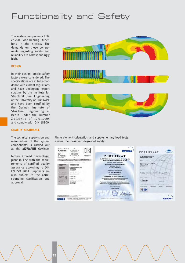
Functionality and Safety
20
Finite element calculation and supplementary load tests
ensure the maximum degree of safety.
The system components fulfil
crucial load-bearing funct-
ions in the statics. The
demands on these compo-
nents regarding safety and
reliability are correspondingly
high.
DESIGN
In their design, ample safety
factors were considered. The
specifications are in full accor-
dance with current regulations
and have undergone expert
scrutiny by the Institute for
Structural Steel Engineering
at the University of Brunswick
and have been certified by
the German Institute of
Structural Engineering in
Berlin under the number
Z-14.4-441 of 12.01.2004
and comply with DIN 18800.
QUALITY ASSURANCE
The technical supervision and
manufacture of the system
components is carried out
at the MÜRMANN Gewinde-
technik (Thread Technology)
plant in line with the requi-
rements of certified quality
assurance according to DIN
EN ISO 9001. Suppliers are
also subject to the corre-
sponding certification and
approval.
Mconnect-folder-a4-eng.qxp 17.02.2010 15:52 Uhr Seite 21
21
Rational application via modular systemAt the conception of the
m·connect product program,
rational application stood at
the forefront together with
functionality and design:
simple engineering, simple
application and simple install-
ation.
A prerequisite was to con-
ceive the product range as a
modular system.
Standardised according to
uniform criteria, the individual
components are assembled
herein as modules. Through
strict classification as to
loads and connection geo-
metries, the components wit-
hin a load group are comp-
atible with regard to connect-
ions. They can consequently
be assembled at will to form
functional load chains. At the
same time the combination of
components of different load-
bearing capacity is excluded.
For projects, engineering can
be executed very easily and
safely using this catalog or,
even more conveniently, by
electronic means with our
CONNCAD® software program
(see p. 23).
As integrated elements in
suspension and support con-
structions, the m·connect-load chains fulfil important
tasks in building structures.
The range of applications is
considerable and the multiple
combination possibilities of
individual components are
designed to fulfil almost all
practical demands.
Compression strut
Compression strut with
weld-on stud
Connection plate
Cap nut
Fork head
Connection sleeve
Adjustable compression strut
Tension rod
Structural attachment
Compression strut
Compression strut with
weld-on stud
Connection plate
Cap nut
Fork head
Connection sleeve
Adjustable compression strut
Tension rod
Structural attachment
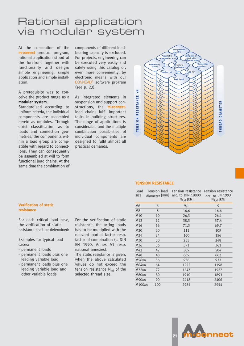
Verification of static resistance
For each critical load case,
the verification of static
resistance shall be determined:
Examples for typical load
cases:
- permanent loads
- permanent loads plus one
leading variable load
- permanent loads plus one
leading variable load and
other variable loads
For the verification of static
resistance, the acting loads
has to be multiplied with the
relevant partial factor resp.
factor of combination (s. DIN
EN 1990, Annex A1 resp.
national annexes).
The static resistance is given,
when the above calculated
values do not exceed the
tension resistance NRd of the
selected thread size.
TENSION RESISTANCE
Loadsize
M6
M8
M10
M12
M16
M20
M24
M30
M36
M42
M48
M56x4
M64x4
M72x4
M80x4
M90x4
M100x4
Tension load
diameter [mm]
6
8
10
12
16
20
24
30
36
42
48
56
64
72
80
90
100
Tension resistance
acc. to EN 1993 NR,d [kN]
9
16,4
26,1
37,4
69,7
109
156
248
361
504
662
933
1198
1527
1893
2406
2954
Tension resistanceacc. to DIN 18800
NR,d [kN]
9,1
16,6
26,3
38,3
71,3
111
160
255
371
509
669
936
1222
1547
1910
2418
2985
Mconnect-folder-a4-eng.qxp 17.02.2010 15:52 Uhr Seite 22

22
For surface protection against
corrosion, selection can be
made from the usual types
of corrosion protection:
Only materials meeting DIN,
DIN-EN standards or ASTM are
used. For load-bearing com-
ponents, only materials with
guaranteed strength values
are selected.
Fork head
Tension rod
Pin
Cap nut
Connecting sleeve
Connection plate
Connection lug
Fork head
Tension rod
Pin
Cap nut
Connecting sleeve
Connection plate*
Connection lug
Fork head
Tension rod
Pin
Cap nut
Connecting sleeve
Connection plate**
Connection lug
Material
GS20Mn5V
S460
8.8
GS20Mn5N
GS20Mn5V
S355
S355
1.4468 (1.4462)
1.4301
1.4571
1.4418
1.4301
1.4301
S355
1.4462
1.4468 (1.4462)
1.4462
1.4462
1.4468 (1.4462)
1.4462
S355
1.4462
Yield strengthfyk in N/mm2
360
460
640
300
360
325-360
325-360
360
460
640
360
360
325-360
460
360
460
640
360
360
325-360
460
System from carbon steel
Ultimate stress
fuk in N/mm2
500
625
800
500
500
490
490
500
625
800
490
490
490
640
500
625
800
500
500
490
640
Breaking elong-
ation A5 in %
22
17
12
22
24
20
20
22
12
-
14
20
20
20
25
22
25
25
20
20
20
25
Notch impact
KV (ISO) [J/°C]
27 / -30
40 / -20
30 / 20
27 / -20
27 / -30
27 / -20
27 / -20
50 / 20
90 / 20
90 / 20
55 / 20
90 / 20
90 / 20
27 / -20
90 / 20
50 / 20
90 / 20
90 / 20
50 / 20
90 / 20
27 / -20
60 / 20
* Construction measures against contact
corrosion are set out in the building
supervision certificate Z-30.3-6.
** We reserve the right to use, in
agreement with the customer, materials
of equal quality according to building
supervision certificate Z-14.4-441.System from Duplex steel (Corrosion resistance class 4)
System from special steel (Corrosion resistance class 2)
Component
Fork head
Pin
Lock ring
Cap nut
Tension rod
Outer threads
Connecting sleeve
Connection plate**
and lug
untreated
glass bead bla-
sted
polished
1 untreated
blasted
bright
black
bright
rough rolled
bright
blasted
rough rolled
2 undercoated
primer
centrifuge galv.
black
primer
primer
bright
primer
primer
Protection systems for carbon steel systems
3 hot dip galvanized
centrifuge galv.
centrifuge galv.
stainless steel
centrifuge galv.
hot dip g.
brushed
centrifuge galv.
hot dip g.
4 galvanized
Oberflächen der Edelstahlsysteme
MATERIALS
CORROSION PROTECTION
Supplia
ble
only
for
length
s of te
nsion
rods
� 3
m
Mconnect-folder-a4-eng.qxp 17.02.2010 15:52 Uhr Seite 23

23
CONNCAD® – Design and engineering program
CONNCAD® - DESIGN ANDENGINEERING PROGRAM
For the swift and simple
design and planning of
m·connect tension rod and
compression strut systems,
the user has our design
and engineering software
CONNCAD® at his disposal.
The basis of this special user-
friendly program is the
m·connect modular system
(p. 21) and the coding of
components (p. 24).
CONNCAD® helps to save
time and cut costs. Just a
few mouse clicks suffice to
generate ready-to-order
design documentation, to
scale and in the required
detail.
By way of the appropriate
interfaces the designs can be
fed into common CAD pro-
grams. The usual time and
effort spent on planning is
thereby reduced to a mini-
mum. CONNCAD® is availa-
ble on our homepage under
www.mconnect.eu or for
downloading free of charge.
CONNCAD®: The design software
for tension rod and compression
strut systems
CONNCAD®: All essential functions at a glance Individual project administration as
a tree structure
Choice of configurations
The result - optimum design
Direct export to various
CAD programs
Simple individual selection
of catalog parts
Mconnect-folder-a4-eng.qxp 17.02.2010 15:52 Uhr Seite 24
Code numbers for clear identification
24
Position
2Position
3Position
4Position
5Position
6Position
7Position
8
Productgroup
Type & design / version / model
01 = Tension rod system
02 = Tension rod system without cap nuts
03 = Tension rod system with cap nuts
(1 connecting sleeve)
04 = Tension rod system without cap nuts
(1 connecting sleeve)
05 = Tension rod system with cap nuts
(2 connecting sleeves)
06 = Tension rod system without cap nuts
(2 connecting sleeves)
11 = Compression strut system without adjustm.
12 = Compression strut system with adjustment
13 = Compression strut system (tube) without adjustm.
14 = Compression strut system (tube) with adjustm.
15 = Compression strut system (tube)
with welded end (without adjustment)
16 = Compression strut system (tube)
with welded end (with adjustment)
31 = Tension rod LH/RH Full shaft
32 = Tension rod LH/RH to roll shaft
41 = Forked end, right-hand
42 = Forked end, left-hand
43 = Cap nut, right-hand
44 = Cap nut, left-hand
45 = Connecting sleeve LH/RH
46 = Connecting sleeve with lug LH/RH
51 = Compression strut, without adjustm.
52 = Compression strut, with adjustment
53 = Compression strut (tube), without adjustm.
54 = Compression strut (tube), with adjustm.
55 = Compression strut, with weld-on stud
56 = Compression strut (tube), with weld-on stud
60 = Straight lug
61 = Angled lug
62 = Cylindrical lug
63 = Semi-circular lug
64 = Cylindrical double lug
66 = Universal corner lug
67 = Universal double corner lug
68 = Quarter-circle lug
81 = Weld-on stud for compression strut
71 = Triangular plate
72 = Circular plate
73 = Square plate
75 = Cruciform plate
0= -0°
10= -10°
20= -20°
30= -30°
40= -40°
45= -45°
50= -50°
60= -60°
45= -45°
60= -60°
75= -75°
90= -90°
R = steel, crude
P = steel, undercoated
H = steel, hot dip galv.
A = austenite, crude
B = austenite, blasted
C = austenite, brushed
D = duplex steel
crude/ untreated
E = duplex, blasted
F= duplex, brushed
System length in mm
R = steel, crude
P = steel, undercoated
H = steel, hot dip galv.
A = austenite, crude
B = austenite, blasted
C = austenite, brushed
D = duplex steel
crude/ untreated
E = duplex, blasted
F= duplex, brushed
R = steel, crude
P = steel, undercoated
H = steel, hot dip galv.
A = austenite, crude
B = austenite, blasted
C = austenite, brushed
D = duplex steel
crude/ untreated
E = duplex, blasted
F= duplex, brushed
R = steel, crude
P = steel, undercoated
H = steel, hot dip galv.
D = duplex steel
crude/ untreated
06=M6 42= M42
08=M8 48= M48
10=M10 56= M56x4
12=M12 64= M64x4
16=M16 72= M72x4
20=M20 80= M80x4
24=M24 90= M90x4
30=M30 100= M100x4
36=M36
06=M6 42= M42
08=M8 48= M48
10=M10 56= M56x4
12=M12 64= M64x4
16=M16 72= M72x4
20=M20 80= M80x4
24=M24 90= M90x4
30=M30 100= M100x4
36=M36
06=M6 42= M42
08=M8 48= M48
10=M10 56= M56x4
12=M12 64= M64x4
16=M16 72= M72x4
20=M20 80= M80x4
24=M24 90= M90x4
30=M30 100= M100x4
36=M36
06=M6 42= M42
08=M8 48= M48
10=M10 56= M56x4
12=M12 64= M64x4
16=M16 72= M72x4
20=M20 80= M80x4
24=M24 90= M90x4
30=M30 100= M100x4
36=M36
6-
6-
6-
System diameter Material class,rod surface
Additional information
CCoommppoonneennttss ooff tthhee tteennssiioonn rroodd aanndd ccoommpprreessssiioonn ssttrruutt ssyysstteemmss
CCoonnnneeccttiinngg ppllaatteess aanndd lluuggss
TTeennssiioonn rroodd aanndd ccoommpprreessssiioonn ssttrruutt ssyysstteemmss
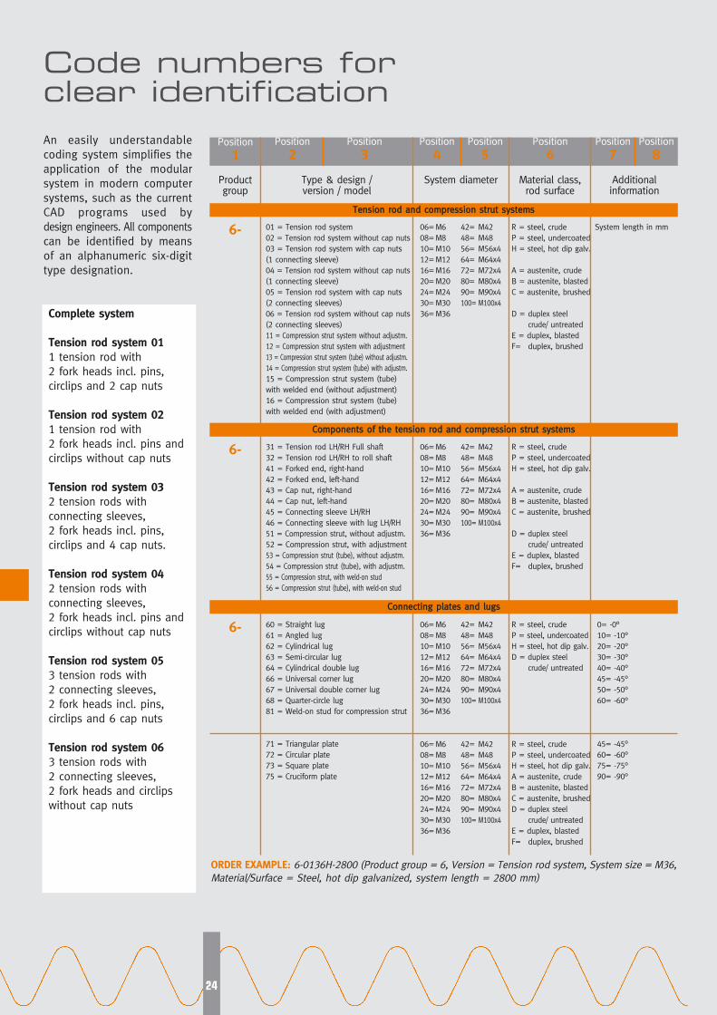
ORDER EXAMPLE: 6-0136H-2800 (Product group = 6, Version = Tension rod system, System size = M36,
Material/Surface = Steel, hot dip galvanized, system length = 2800 mm)
An easily understandable
coding system simplifies the
application of the modular
system in modern computer
systems, such as the current
CAD programs used by
design engineers. All components
can be identified by means
of an alphanumeric six-digit
type designation.
Complete system
Tension rod system 011 tension rod with
2 fork heads incl. pins,
circlips and 2 cap nuts
Tension rod system 021 tension rod with
2 fork heads incl. pins and
circlips without cap nuts
Tension rod system 032 tension rods with
connecting sleeves,
2 fork heads incl. pins,
circlips and 4 cap nuts.
Tension rod system 042 tension rods with
connecting sleeves,
2 fork heads incl. pins and
circlips without cap nuts
Tension rod system 053 tension rods with
2 connecting sleeves,
2 fork heads incl. pins,
circlips and 6 cap nuts
Tension rod system 063 tension rods with
2 connecting sleeves,
2 fork heads and circlips
without cap nuts
Position
1
Mconnect-folder-a4-eng.qxp 17.02.2010 15:52 Uhr Seite 25

25
Creative and efficient:
• Comprehensive product
program as a modular
system ensures complete
solutions to problems.
• Broad field of application
from M6 to M100, all from
one source, rod lengths
up to 12 m.
• Slim and elegant product
design for imaginative
solutions.
• Dependable designs due
to standardized
connection lugs.
• Variable adaptation of
surface treatment
to requirements.
• Cost-cutting design
and planning using
CONNCAD® software
program.
• Optimum solutions in
special cases through
technical support.
Dependable and safe:
• Certified safety through
stress reports and
overload testing.
Approval by the German
Institute of Structural
Engineering, Berlin.
• Use of materials with
guaranteed tensile values
and high cold tenacity.
• High safety levels for
connections by including
connection lugs in the
approval process.
• Competence through
40 years’ experience
in hanger and thread
technology.
• High and constant
quality level through
quality management
according to DIN/ISO 9001
and ASME NF.
Simple assembly:
• No time-consuming
approval procedures
required, due to DIBt
(=Deutsche Institut für
Bautechnik) certification.
• Simplification of inquiry
and ordering procedures
using the CONNCAD®
process.
• Reduction in installation
time through preassembly
at the works.
• No particular sealing
required in fork heads
due to pocket hole
design.
• Balancing of on-site
dimension tolerances
through wide range of
length adjustment.
• Simple length adjust-
ability using left-hand /
right-hand thread
(turnbuckle function)
and flat faces.
• Checking of minimum
engagement depths by
enclosing rod thread
with cap nut.
• Prompt servicing by
our experts.
m·connect tension rod and
compression strut systems
offer great benefits to
• architects
• structural engineers and
• building contractors
in equal measure
Special features at the same
time ensure optically attractive
and reliable application, to-
gether with great economy.
For profitable order the opti-
mization of processing total
costs is decisive.
Special benefits for users
Design
Components
Assembly
Installed total costs
Mconnect-folder-a4-eng.qxp 17.02.2010 15:52 Uhr Seite 26
26
m·connect tension rod and
compression strut systems
are of crucial significance as
load-bearing components for
the load-bearing capacity of
the whole construction.
Observation of the following
instructions is a prerequisite
for trouble-free functioning.
If the components in the tensi-
on rod system are subse-
quently subjected to thermal
or mechanical treatment, the
building supervision certifica-
tion loses its validity.
1. Delivery condition
1.1. The m·connect tension rod
and compression strut
systems are preassembled
and supplied as ready-to-
install load chains with the
corresponding markings.
1.2. If connection lugs are
also supplied, they are
separately marked with the
installation position and tied
to the tension rod system
with binding wire.
1.3. To guarantee the given
load capacity of the connect-
ion lugs, the welding speci-
fications under Point 3 of these
instructions must be strictly
adhered to.
2. Packaging
2.1. Wooden laths are used
to protect the tension rod
systems from damage. The
delivery packages are wrap-
ped in foil as protection
against dust and dirt.
Wooden crates are used for
the delivery of individual
components.
2.2. On delivery the compo-
nents must be inspected for
transport damage and protec-
ted against moisture by storage
in closed rooms until assembly.
3. Welding procedure forconnection lugs
The following procedure is
recommended when welding
connection lugs:
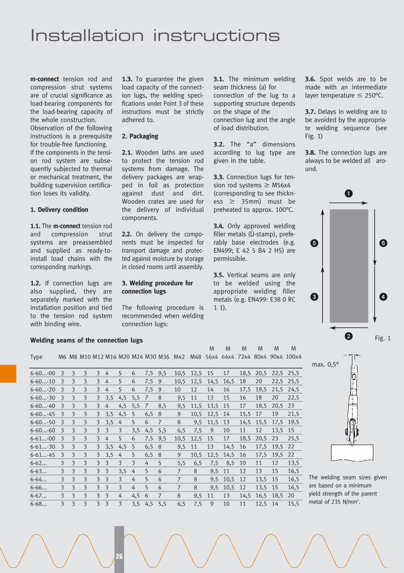
3.1. The minimum welding
seam thickness (a) for
connection of the lug to a
supporting structure depends
on the shape of the
connection lug and the angle
of load distribution.
3.2. The “a” dimensions
according to lug type are
given in the table.
3.3. Connection lugs for ten-
sion rod systems M56x4
(corresponding to see thickn-
ess 35mm) must be
preheated to approx. 100°C.
3.4. Only approved welding
filler metals (Ü-stamp), prefe-
rably base electrodes (e.g.
EN499; E 42 5 B4 2 H5) are
permissible.
3.5. Vertical seams are only
to be welded using the
appropriate welding filler
metals (e.g. EN499: E38 0 RC
1 1).
3.6. Spot welds are to be
made with an intermediate
layer temperature � 250°C.
3.7. Delays in welding are to
be avoided by the appropria-
te welding sequence (see
Fig. 1)
3.8. The connection lugs are
always to be welded all aro-
und.
Installation instructions
�
�
�
�
Type
6-60...-00
6-60...-10
6-60...-20
6-60...-30
6-60...-40
6-60...-45
6-60...-50
6-60...-60
6-61...-00
6-61...-30
6-61...-45
6-62...
6-63...
6-64...
6-66...
6-67...
6-68...
M6
3
3
3
3
3
3
3
3
3
3
3
3
3
3
3
3
3
M8
3
3
3
3
3
3
3
3
3
3
3
3
3
3
3
3
3
M10
3
3
3
3
3
3
3
3
3
3
3
3
3
3
3
3
3
M12
3
3
3
3
3
3
3
3
3
3
3
3
3
3
3
3
3
M16
4
4
4
3,5
4
3,5
3,5
3
4
3,5
3,5
3
3
3
3
3
3
M20
5
5
5
4,5
4,5
4,5
4
3
5
4,5
4
3
3,5
3
3
4
3
M24
6
6
6
5,5
5,5
5
5
3,5
6
5
5
3
4
4
4
4,5
3,5
M30
7,5
7,5
7,5
7
7
6,5
6
4,5
7,5
6,5
6,5
4
5
5
5
6
4,5
M36
9,5
9
9
8
8,5
8
7
5,5
9,5
8
8
5
6
6
6
7
5,5
M42
10,5
10,5
10
9,5
9,5
9
8
6,5
10,5
9,5
9
5,5
7
7
7
8
6,5
M48
12,5
12,5
12
11
11,5
10,5
9,5
7,5
12,5
11
10,5
6,5
8
8
8
9,5
7,5
M
56x4
15
14,5
14
13
13,5
12,5
11,5
9
15
13
12,5
7,5
9,5
9,5
9,5
11
9
M
64x4
17
16,5
16
15
15
14
13
10
17
14,5
14,5
8,5
11
10,5
10,5
13
10
M
72x4
18,5
18
17,5
16
17
15,5
14,5
11
18,5
16
16
10
12
12
12
14,5
11
M
80x4
20,5
20
19,5
18
18,5
17
15,5
12
20,5
17,5
17,5
11
13
13,5
13,5
16,5
12,5
M
90x4
22,5
22,5
21,5
20
20,5
19
17,5
13,5
23
19,5
19,5
12
15
15
15
18,5
14
M
100x4
25,5
25,5
24,5
22,5
23
21,5
19,5
15
25,5
22
22
13,5
16,5
16,5
16,5
20
15,5
Welding seams of the connection lugs
max. 0,5°
Fig. 1
The welding seam sizes given
are based on a minimum
yield strength of the parent
metal of 235 N/mm2.
Mconnect-folder-a4-eng.qxp 17.02.2010 15:52 Uhr Seite 27
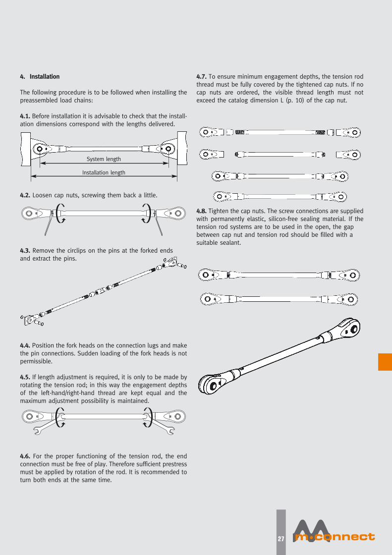
27
4. Installation
The following procedure is to be followed when installing the
preassembled load chains:
4.1. Before installation it is advisable to check that the install-
ation dimensions correspond with the lengths delivered.
4.2. Loosen cap nuts, screwing them back a little.
4.3. Remove the circlips on the pins at the forked ends
and extract the pins.
4.4. Position the fork heads on the connection lugs and make
the pin connections. Sudden loading of the fork heads is not
permissible.
4.5. If length adjustment is required, it is only to be made by
rotating the tension rod; in this way the engagement depths
of the left-hand/right-hand thread are kept equal and the
maximum adjustment possibility is maintained.
4.6. For the proper functioning of the tension rod, the end
connection must be free of play. Therefore sufficient prestress
must be applied by rotation of the rod. It is recommended to
turn both ends at the same time.
4.7. To ensure minimum engagement depths, the tension rod
thread must be fully covered by the tightened cap nuts. If no
cap nuts are ordered, the visible thread length must not
exceed the catalog dimension L (p. 10) of the cap nut.
4.8. Tighten the cap nuts. The screw connections are supplied
with permanently elastic, silicon-free sealing material. If the
tension rod systems are to be used in the open, the gap
between cap nut and tension rod should be filled with a
suitable sealant.
System length
Installation length
Mconnect-folder-a4-eng.qxp 17.02.2010 15:52 Uhr Seite 28

MÜRMANN GmbH
Wölzower Weg 27 • 19243 Wittenburg - Germany
Phone +49 (0) 3 88 52 / 6 58-0
Fax +49 (0) 3 88 52 / 6 58-31
www.muermann-gewindetechnik.de
www.mconnect.eu
Mconnect-folder-a4-eng.qxp 17.02.2010 15:52 Uhr Seite 1


![TORQUE ROD-MERCEDES BENZ · 6593503506 Mercedes NG, SK Length: 579 mm Outer Diameter: 50 mm Diameter [mm]:80mm Rod/Strut: Guide Rod Hole Pitch 1/ Hole Pitch 2: 152/152 Bore Ø 1](https://static.documents.pub/doc/80x56/6069566f3eb4411efd597aa4/torque-rod-mercedes-6593503506-mercedes-ng-sk-length-579-mm-outer-diameter-50.jpg)


