General rights Copyright and moral rights for the publications made accessible in the public portal are retained by the authors and/or other copyright owners and it is a condition of accessing publications that users recognise and abide by the legal requirements associated with these rights. Users may download and print one copy of any publication from the public portal for the purpose of private study or research. You may not further distribute the material or use it for any profit-making activity or commercial gain You may freely distribute the URL identifying the publication in the public portal If you believe that this document breaches copyright please contact us providing details, and we will remove access to the work immediately and investigate your claim. Downloaded from orbit.dtu.dk on: Jun 01, 2020 Terahertz orbital angular momentum modes with flexible twisted hollow core antiresonant fiber Stefani, Alessio; Fleming, Simon C.; Kuhlmey, Boris T. Published in: APL Photonics Link to article, DOI: 10.1063/1.5016283 Publication date: 2018 Document Version Publisher's PDF, also known as Version of record Link back to DTU Orbit Citation (APA): Stefani, A., Fleming, S. C., & Kuhlmey, B. T. (2018). Terahertz orbital angular momentum modes with flexible twisted hollow core antiresonant fiber. APL Photonics, 3(5), [051708]. https://doi.org/10.1063/1.5016283
Transcript
General rights Copyright and moral rights for the publications made accessible in the public portal are retained by the authors and/or other copyright owners and it is a condition of accessing publications that users recognise and abide by the legal requirements associated with these rights.
Users may download and print one copy of any publication from the public portal for the purpose of private study or research.
You may not further distribute the material or use it for any profit-making activity or commercial gain
You may freely distribute the URL identifying the publication in the public portal If you believe that this document breaches copyright please contact us providing details, and we will remove access to the work immediately and investigate your claim.
Downloaded from orbit.dtu.dk on: Jun 01, 2020
Terahertz orbital angular momentum modes with flexible twisted hollow coreantiresonant fiber
Stefani, Alessio; Fleming, Simon C.; Kuhlmey, Boris T.
Published in:APL Photonics
Link to article, DOI:10.1063/1.5016283
Publication date:2018
Document VersionPublisher's PDF, also known as Version of record
Link back to DTU Orbit
Citation (APA):Stefani, A., Fleming, S. C., & Kuhlmey, B. T. (2018). Terahertz orbital angular momentum modes with flexibletwisted hollow core antiresonant fiber. APL Photonics, 3(5), [051708]. https://doi.org/10.1063/1.5016283
Terahertz orbital angular momentum modes with flexible twisted hollow coreantiresonant fiberAlessio Stefani, Simon C. Fleming, and Boris T. Kuhlmey
Citation: APL Photonics 3, 051708 (2018); doi: 10.1063/1.5016283View online: https://doi.org/10.1063/1.5016283View Table of Contents: http://aip.scitation.org/toc/app/3/5Published by the American Institute of Physics
Articles you may be interested inAll-dielectric rod antenna array for terahertz communicationsAPL Photonics 3, 051707 (2018); 10.1063/1.5023787
Tutorial: Terahertz beamforming, from concepts to realizationsAPL Photonics 3, 051101 (2018); 10.1063/1.5011063
Terahertz orbital angular momentum modes with flexibletwisted hollow core antiresonant fiber
Alessio Stefani,1,2,a Simon C. Fleming,1 and Boris T. Kuhlmey11Institute of Photonics and Optical Science (IPOS), The School of Physics,The University of Sydney, Sydney, NSW 2006, Australia2DTU Fotonik, Department of Photonics Engineering, Technical University of Denmark,2800 Kongens Lyngby, Denmark
(Received 17 November 2017; accepted 9 April 2018; published online 30 April 2018)
The rapidly increasing availability of sources and detectors has brought the field of THz radiation,also known as millimeter waves, from an interesting physics regime to the real world, with applica-tions in security, telecommunications, characterization of biological and solid-state matter, and manyothers.1,2 These various applications require, on top of generating and detecting the desired radiation,means of transporting and manipulating the fields, i.e., waveguides and components such as filters,couplers, mode combiners, and splitters, and so on.
In the context of guiding THz radiation, there has been a large effort in realizing waveguideswhich are at the same time small and flexible and have low loss. The size of the waveguides isconstrained by the wavelength to be guided, and therefore, THz waveguides must have millimeter tocentimeter sized cross sections, which makes them very rigid. Furthermore, the material providingthe confinement strongly affects the loss of the waveguides; unlike at optical wavelengths, there isno material with very low loss in the THz region so that the use of hollow waveguides is necessary.
aAuthor to whom correspondence should be addressed: [email protected].
051708-2 Stefani, Fleming, and Kuhlmey APL Photonics 3, 051708 (2018)
A variety of types of hollow waveguides have been studied for THz, which may be separated intometallic, dielectric, and hybrid waveguides (including metamaterial waveguides).3–9 Metallic hollowwaveguides can have subwavelength cross section and have relatively low loss. Those characteristicsarguably make them the current best option for THz waveguides. Metamaterial hollow waveguidesoffer the potential for control of the radiation,5 can be subwavelength,6 and have potentially lowloss.7 However, both complexity of fabrication and the relative lack of research in this field leavedoubts about their real potential. Dielectric THz hollow waveguides are the scaled version of theirmore successful optical counterpart and have been investigated in the form of Kagome structures,10,11
simple capillaries,12 antiresonant structures,13 and several other variations.8,9 Although some of thesehave the possibility of achieving excellent guidance, the relationship between loss and size has meantthat realizations of this approach are large rigid structures that were of little practical use. Leavingaside the rigidity issue temporarily, there is one class of hollow dielectric waveguides that deservesmore detailed consideration, mostly because of the greatly expanding recent interest and results inthe optical domain: antiresonant fibers.
Antiresonant fibers14 have been, in the last five years, dominating the panorama of hollow corefibers. The reason is that a very simple structure, i.e., a circular array of capillaries, allows guidanceof very large bandwidths with very low loss, almost independently of the absorption of the materialused for the structure. Moreover, by tuning the few parameters of this structure, it is possible toobtain single mode operation in large cores15 and to tune the bending loss of the structure.16 In thecontext of THz, the realization of such fibers allows reducing the overall structure size compared tobandgap or Kagome structures, controlling the modal properties and further reducing the waveguideloss with any material. Although interesting, this is not sufficient unless the waveguide can be madeusable in practical applications. The enabling factor behind this work is the use of a novel material forwaveguides, namely, polyurethane (PU), Young’s modulus of which is 2–3 orders of magnitude lowerthan conventional waveguide dielectrics and allows even centimeter sized tubes, rods, and structuresto be bent with a radius 10 times the diameter. This means a 1 cm diameter fiber can be bent in a 10 cmradius circle (an example is shown in Fig. S1 of the supplementary material). This unique propertyallows the fabrication of waveguides with large cross sections that are still flexible and allows forfurther mechanical manipulations of the fibers. The specific manipulation we will exploit in this paperis twisting of the structure in a controlled and reversible way.
The idea of twisting fiber structures is very interesting because it enables creating modes withan orbital angular momentum (OAM)17–19 and controlling the state of polarization and the fiber’soptical activity.20,21 It should be kept in mind that in order to obtain any effect, the fiber to be twistedcannot be cylindrically symmetric. There have been interesting recent advances in this research bytwisting photonic crystal fibers (PCFs). So far, there have been two ways to give PCFs a twist: bypost-processing with a CO2 laser17,18 or by twisting the preform during fiber drawing.18,22,23 Bothmethods result in a permanent twist of the fiber and the twist occurs at high temperatures where thematerial viscosity is low. When in a solid state, mechanical, and therefore reversible, twist of silicafibers cannot be used to produce twist rates high enough to achieve the desired properties17–23 becauseof the inherent material stiffness. Moreover, even when fabricated with a permanent deformation,these twisted structures have been realized only in the optical domain and only theoretically suggestedin the THz, once more because of the combination of size and necessary deformation required toachieve structures showing interesting properties.
The interest behind being able to realize modes that have orbital angular momentum derivesfrom the plethora of applications that this class of modes has found in 25 years of investigation,24–27
including, but not limited to, imaging and microscopy,28 quantum photonics and entangled states,29
optical tweezers,30 and optical communications.31 Modes carry orbital angular momentum when theirphase structure is rotating. Assuming an eiωt time dependence, they have an optical vortex along theiraxis and an azimuthal phase dependence of the form e−i`φ , with ` being a positive or negative integerand φ being the angular coordinate, and they carry a momentum of `~ per photon. The helical phasefront and the azimuthal 2π` phase change require a phase singularity in the middle which leads toa central intensity null.27 Because of the large interest involved, there have been many proposals onhow to generate OAM modes, including phase plates,32 diffractive elements using holograms33 orspatial light modulators,34 mode conversion with cylindrical lenses,24 metasurfaces,35,36 microbend
051708-3 Stefani, Fleming, and Kuhlmey APL Photonics 3, 051708 (2018)
FIG. 1. Schematic of the proposed process. A fundamental-like mode is coupled into the fiber which is mechanically twistedand therefore allows for coupling from the fundamental mode to an OAM-possessing mode.
gratings in fibers,37,38 and twisted PCFs.18 The generation of OAM for THz radiation has been donesimilarly, by using some of the techniques also used for optical beams.39–43 However, the ability togenerate OAM within a waveguide in a tunable manner is very appealing both in the optical andespecially in the THz domain where this combination was not possible before.
In this paper, we report the realization of a simple, hollow core antiresonant waveguide whichis flexible and opens up a new class of THz waveguides. The flexibility of the waveguide is used totwist the fiber along its axis and to create THz vortex modes possessing orbital angular momentum,as represented in Fig. 1. THz time domain spectroscopy (TDS) is used to measure the vortex natureof OAM modes.
FLEXIBLE HOLLOW CORE WAVEGUIDE
Polyurethane (PU) has a Young’s modulus orders of magnitude lower compared to silica andcan withstand elongations of 600%,44 making it effectively a rubber-like elastic material. The abilityto fiber-draw PU and the possibilities to apply its property to elastically deform have been recentlydemonstrated in the realization of a tunable metamaterial.45 These mechanical properties make PU aperfect candidate for realizing a structure that can be twisted mechanically. The choice of a hollow corestructure is due to both the poor optical properties of polyurethane and the potential of this structureto be scaled at any wavelength, independently from the material properties, in particular, loss. Asalready mentioned, of the class of hollow core structures, the antiresonant tube lattice structure isthe simplest and the most obvious choice. The proposed fiber is realized by six PU tubes arrangedin a circle, as shown in the inset of Fig. 2(a) and the schematics in Figs. 1 and 3(a). The tubes arecommercially available with large outer sizes and are fiber-drawn to about 3 mm in outer diameter.The fiber structure is held together by gluing the tubes to a plastic disc on each end, while the middleis free standing. The thickness of the disc is 5 mm and a hole was drilled to size to accommodatethe tube lattice structure. While such a structure can be drawn to smaller dimensions if necessary,the structure was suitable without the necessity of further scaling for testing the principle in the THzregime. The resulting fiber core has a 3 mm diameter, and the capillaries have thickness of abouta = 400 µm. Using phase resolved propagation measurements in 3 and 5 mm PU samples, we
FIG. 2. (a) Normalized measured transmission through 10 cm of the antiresonant PU fiber. A photograph of the cross sectionof the fiber is shown in the inset. The red dotted lines indicate the expected frequencies of the transmission minima calculatedwith Eq. (1). Data are normalized to the maximum measured power. (b) Simulated propagation loss of the fundamental mode.The red dotted line marks 2 dB/m loss.
051708-4 Stefani, Fleming, and Kuhlmey APL Photonics 3, 051708 (2018)
FIG. 3. (a) Various twisting and un-twisting steps and schematics of the twisted fiber offering a view of the waveguide whentwisted. For information about the transmission of the fiber when twisted refer to the “spectral transmission with twist” sectionin the supplementary material. (b) Schematic of the near-field raster scan THz TDS setup.
calculated a refractive index of n = 1.6 at 0.3 THz. This yields resonances at frequency multiples off R = 300 GHz, calculated by using the analytical expression for antiresonant fibers with an air core,14
fR =c
2a√
n2 − 1, (1)
where c is the speed of light.The fiber was characterized in a THz time domain spectroscopy system.2 Figure 2(a) shows the
transmitted spectrum through 10 cm of the fiber for the frequency range 0.1–1.1 THz. As expected,bands of high transmission are visible. The minima of the transmission correspond quite well to theanalytical calculation of the tube walls’ resonances [red dotted lines in Fig. 2(a)]. Similar transmissioncurves, with identical resonance limited bands, were obtained with fibers 12, 14.5, 17.5, and 20 cmlong. However, because of the size of the waveguide and realization of the structure (how the tubesare kept in place), cutback measurements to obtain propagation losses were not possible: whencomparing the transmission between the various sample lengths, the coupling efficiency played asignificant role and a comparison between them leads to errors larger than the actual values. This isalso due to the fiber being multimoded in a good part of the transmission window. As a reference,we measured ∼10 dB loss including coupling and propagation around 0.8 THz for the 10 cm fiber.Simulations of the structure using a commercial finite element solver (COMSOL) show minimumpropagation loss approaching 0.1 dB/m for the fundamental mode [Fig. 2(b)]. For more information,see the “loss of the high order modes” section in the supplementary material. The simulated structurehas a core diameter of 3.2 mm and capillaries with 3 mm diameter, 400 µm wall thickness, anda refractive index of 1.6. The loss of PU is set to a constant value of 1 dB/cm for all frequencieswhich is the measured value of the bulk material at 0.5 THz. While such low simulated lossesdemonstrate the potential of this fiber, they are only found over a relatively narrow band and assumea perfect structure. It is instead reasonable to consider the lowest loss to be around 1-2 dB/m for thefundamental mode in the transmission bands of interest to this investigation. Note that loss could befurther reduced with thinner and more widely spaced capillaries. Effective single mode behavior couldbe achieved by carefully choosing the ratio of the capillaries and core diameter15 or by twisting thestructure.23
TWISTED FIBER FOR OAM GENERATION
The realized structure and its flexibility (also illustrated in Fig. S1 of the supplementary material)give us the possibility to investigate the effects of twist on the guided modes. The fiber was mechan-ically twisted, by keeping one end fixed and rotating the other. The amount of twist could be tunedand the twist is reversible. The twist we could apply was limited by the structural stability of thetube assembly: beyond a certain amount of twist either the adhesive would fail and the tube bundledismantle or one of the tubes would slip into the core. For the lengths involved in this experiment,i.e., 10–20 cm, around 8 cm twist period was the shortest achievable reliably. Longer fibers allowedshorter twist periods, probably because of the force on the adhesive being lower. Figure 3(a) shows
051708-5 Stefani, Fleming, and Kuhlmey APL Photonics 3, 051708 (2018)
side images of the fiber during the twisting and un-twisting process and schematics of the twistedfiber.
In order to measure the modal content, near-field raster scan measurements were performed atthe output end of the waveguide. The great advantage of THz TDS is that it allows us to acquireinformation on the intensity, electric field, and phase of the modes and also it allows analyzingtheir time evolution. With this technique, the amplitude of the THz electric field (not its envelope orintensity) is directly measured as a function of the time delay between the pump and probe pulsesgenerating and detecting the broadband THz pulses. Therefore, the time delay allows sampling ofthe THz electric field in time. The measured amplitude of the electric field can be mathematicallyprocessed with a Fourier transformation to obtain the complex electric field as a function of frequency.Accessing the complex field is necessary for obtaining full information about modes/fields where thephase of the electric field is a characteristic feature, as it is for modes carrying OAM. A schematic ofthe measurement system is shown in Fig. 3(b). The scan was performed on a 2.4 × 2.4 mm area withlateral steps of 75 µm, at a distance of about 50 µm from the end-facet, and 64 ps time delay, resultingin a frequency resolution of 15 GHz. Photoconductive antennas were used for the THz generation(EKSPLA EMT-08) and detection (near-field probe TeraSpike TD-800-X-HR). The emitter generatesa linear polarization (in the x direction), and the detection antenna was aligned to be sensitive to thefield component aligned in the same direction as that of the excitation only. This limitation did notaffect the intended ability to characterize orbital angular momentum modes. It did however hinderour ability to explore some of the expected effects of the twist on the polarization.
The measured intensity of the x-component of the modal fields (one for each transmission window0.2, 0.5, and 0.72 THz) of the 10 cm long fiber twisted with a 10 cm period is shown in Fig. 4(b).In the lowest two bands, the intensity is consistent with fields mostly composed of the fundamentalmode, while the fields in the 0.72 THz band show a different profile, consistent with a superpositionof modes, both in the twisted and untwisted cases. When twisted, a central singularity appears in thefield distribution. Such an intensity profile is not surprising given the helicoidal fiber supports vortexmodes with a central zero in the intensity. The analysis of the electric field distribution and its phaseprofile confirms that the mode possesses orbital angular momentum having a 2π spiral phase front,as shown in Fig. 5. It should be noted that the intensity profiles and electric field distributions forthe different frequencies within each transmission band are similar, implying that OAM is generatedat every frequency between 0.6 and 0.9 THz. The electric field and phase distribution measured inlower frequency bands do not show significant variations from the fundamental mode; however, as we
FIG. 4. Mode intensity profile |Ex |2 at the end facet of (a) a 17.5 cm long untwisted fiber and (b) the 10 cm long fiber twisted
with a 10 cm twist period in the 3 main transmission bands. The color scale is used as an indication to be able to comparemode intensities within the same measurement but should not be used to compare intensities of different measurements as thevalues are strongly dependent on the measurement parameters.
051708-6 Stefani, Fleming, and Kuhlmey APL Photonics 3, 051708 (2018)
FIG. 5. Intensity profile |Ex |2, x-component of the electric field, and the phase measured at 0.72 THz.
FIG. 6. Time evolution of the intensity profile |Ex |2, x-component of the electric field, and the phase at 0.72 THz. Multimedia
view: https://doi.org/10.1063/1.5016283.1
did not measure the cross polarization, it is possible that the polarization state has changed betweenthe input and output.
Taking advantage of the time resolved nature of the measurement performed and using a win-dowed Fourier transform (time window of 26 ps), we obtain the time evolution of the various fieldcomponents at selected frequency bands. A video with the evolution of the intensity, electric field,and phase measured at 0.72 THz is included as a media file (Fig. 6) (Multimedia view). The electricfield has two lobes opposite in sign spiraling around the fiber axis with time. Similar information isobtained by the evolution of phase, showing the rotating phase structure typical of modes with OAM.Figure 7 shows the isophase wavefronts’ evolution in time for the case with OAM (0.72 THz) and,
FIG. 7. Isophase evolution of the electric field as a function of time at 0.5 THz and 0.72 THz.
051708-7 Stefani, Fleming, and Kuhlmey APL Photonics 3, 051708 (2018)
for comparison, without OAM (0.5 THz). This measurement is a clear representation of the vortexnature of the field. The spacing between 2 events with the same phase corresponds to one propagationwavelength traveling at the phase velocity. The intensity profile [Fig. 6 (Multimedia view) and video]clearly shows the pulsed nature of the beam, with a much longer time duration compared to a singleoptical cycle.
DISCUSSION—NUMERICAL INVESTIGATION
The field generated and measured clearly has OAM, but the appearance of it is not that of aclean integer OAM mode, for which the phase singularity would be centered, the intensity profilesymmetric, and the phase profile radially uniform.
In order to better understand the process of OAM mode generation in this fiber, finite elementsnumerical simulations using a helical coordinate system transformation17,18,21 were performed. Inall the simulations reported in the paper, a mode is considered to be guided in the core when morethan 50% of the square of the electric field is contained in the circle inscribed within the capillaries.In the lower frequency transmission bands (0.2 and 0.5 THz), the fiber only supports one core modewhich does not have OAM in the twist rates’ range used in the experiments. Higher twist allowsmodes carrying OAM to be supported, but they are quite lossy. This explains why we do not measureOAM modes in the lower bands. In the 0.6-0.9 THz transmission band, the straight fiber supportsmultiple guided modes, which allows guidance of OAM modes if properly excited, as also previouslynumerically reported for a similar structure at a similar frequency.46 When twisted with 10 cm period,the fiber still supports the fundamental mode, although the degeneracy in polarization is lifted, aswell as other modes all carrying OAM. It should be remembered that in circularly symmetric opticalfibers there are 4 possible modes that can carry OAM for ` = 1, consisting of the LP11 manifold: TE01,TM01, HE21
odd, and HE21even.38 Modes with similar electric field distributions to all those modes are
supported in the fiber. Figure 8 shows effective refractive indices of the modes in the fiber at 0.72 THzas a function of twist and some of the modes’ profiles and phase. For information on the propagationloss of these modes, see the “loss of the high order modes” section in the supplementary material.
Applying twist removes the degeneracy in the fundamental mode and also in the LP11-like modes.The LP11 manifold mode splits into 4 non-degenerate modes with a similar distribution to the onescarrying OAM in a standard optical fiber. It is, however, the hybrid (HE21-like) modes that carryOAM in this case and the two hybrid modes have opposite rotation direction. At even higher twistrates, some of the modes became very lossy and disappear, and modes with higher order OAM areguided. It should be noted that apparent missing data points arise from coupling of the modes withmodes propagating in the outer tubes and therefore having less than 50% of the field square in the
FIG. 8. Simulated supported modes in the fiber as a function of the twist rate (2π/twist period) at 0.72 THz. Intensity (modulusof the Poynting vector) of modes with respective phase profiles is shown (the black arrows represent the electric field): at 40cm twist period on the left and at 10 cm twist period on the right. Three groups of modes are highlighted: in blue those thatdo not lead to OAM, in red those coming from the LP11-like modes, with green and blue borders for those leading to a ` = ±1OAM, and in black those leading to a ` = 2 OAM.
051708-8 Stefani, Fleming, and Kuhlmey APL Photonics 3, 051708 (2018)
core. At a twist period of 10 cm, the one used in the experiments, there are 3 modes guided: ` = 0and the hybrid modes with ` = 1 and ` = 2. Moreover, at about this twist rate, the fundamental modeand the OAM mode of order 1 have a refractive index crossing, allowing for efficient coupling fromone mode to the other. With effective index differences in the order of 10�3 in this frequency band,the coupling length between the two modes is in the order of 10 cm, even if very little perturbationis considered. This is consistent with the experiment. Moreover, the structure of the fiber and thetwist are not perfect, therefore increasing the coupling between modes. It should be noted that, forthese conditions, the ` = 1 mode is also the mode with the lowest loss [see also Fig. S3(b) in thesupplementary material].
Because of this effect, it is reasonable to assume that we are exciting multiple modes or that theexcited fundamental mode is transferring energy to the OAM mode and therefore what we observeis a superposition of these. This would explain the asymmetry in the measured OAM mode, wherethe field of the fundamental mode is in phase with part of the OAM mode and out of phase withthe opposite side, leading to constructive interference in one position, destructive interference at theposition opposite to it, and a gradient in between. To confirm it, we summed the modes obtainedfrom the numerical simulations and we also made a simple analytical model by summing Laguerre-Gaussian modes, the field of which is defined in cylindrical coordinates as a function of space andtime as follows (as defined in Ref. 27 but adapted to our time evolution convention):
E (r, φ, z, t)=
√2p!
π (p + |` |)!1
w (z)
r√
2w (z)
|` |
e
[−r2
w2(z)
]
L |` |p
(2r2
w2 (z)
)
× e
[−kr2z
2(z2+z2R)
]
e
[i(2p+ |` |+1)tan−1
(z
zR
)]
e−i(kz−ωt+`φ)e−4 ln(2)(t−t0)2
∆t2 , (2)
where w (z)=w (0) [(z2 + z2R)/z2
R]1/2, w(0) is the beam waist, zR is the Rayleigh range, p is the radialorder (the number of radial nodes in the intensity distribution, set to 0 in our calculation), k = 2π/λis the wave vector, λ is the wavelength, ω = 2πc/λ is the wave angular frequency, c is the speedof light, t0 is the arrival time of the maximum of the pulse, and ∆t is the full width half maximumpulse duration. It should be noted that the minus sign in e−i(kz−ωt+`φ) is used for consistency with themathematical formalism used in the data analysis and numerical simulations.
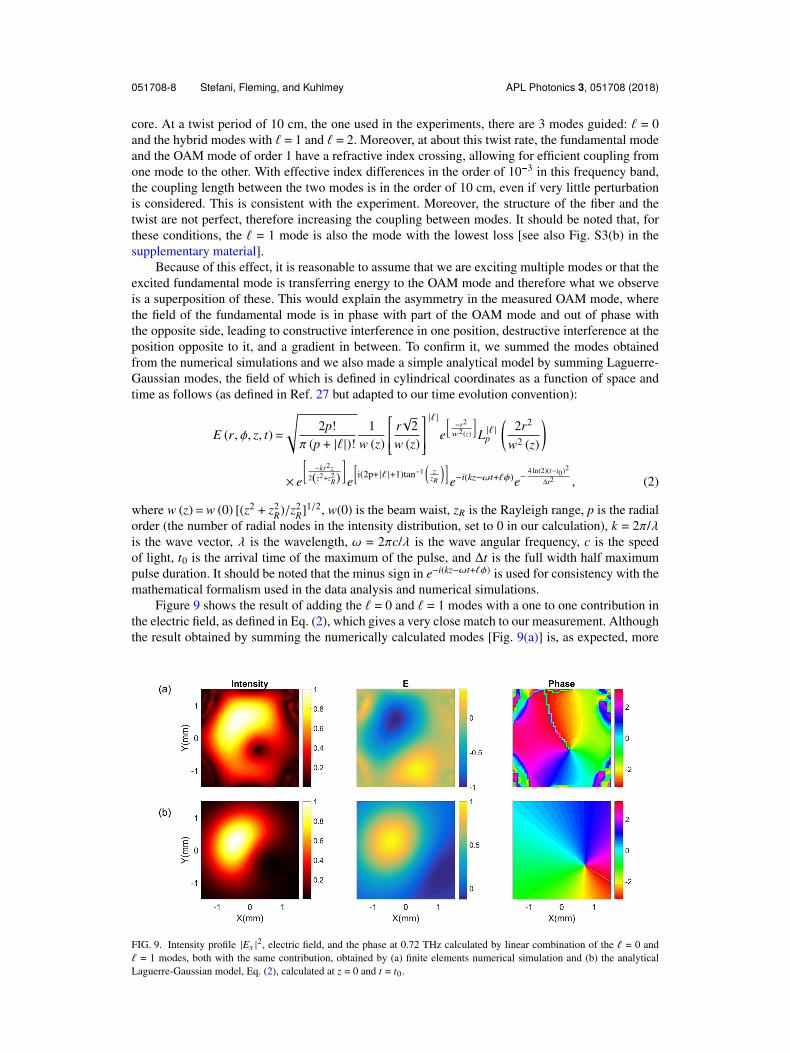
Figure 9 shows the result of adding the ` = 0 and ` = 1 modes with a one to one contribution inthe electric field, as defined in Eq. (2), which gives a very close match to our measurement. Althoughthe result obtained by summing the numerically calculated modes [Fig. 9(a)] is, as expected, more
FIG. 9. Intensity profile |Ex |2, electric field, and the phase at 0.72 THz calculated by linear combination of the ` = 0 and
` = 1 modes, both with the same contribution, obtained by (a) finite elements numerical simulation and (b) the analyticalLaguerre-Gaussian model, Eq. (2), calculated at z = 0 and t = t0.
051708-9 Stefani, Fleming, and Kuhlmey APL Photonics 3, 051708 (2018)
FIG. 10. Time evolution of the intensity profile |Ex |2, electric field, and phase at 0.72 THz generated by analytically adding
the numerical simulated (top) and Laguerre-Gaussian (bottom) modes of order 0 and 1 and with the ` = 0 mode arriving 1.5 psbefore the ` = 1 mode. Multimedia view: https://doi.org/10.1063/1.5016283.2
similar to the measurements than the analytical model [Fig. 9(b)], the two results are quite close,indicating that Laguerre-Gaussian modes are a good and mathematically simpler approximation forthe system. Confirming the presence of the two modes does not explain whether the OAM carryingmode is generated by directional coupling or already excited at the fiber input. We calculated themode overlap integral between the excitation and the two modes (for details see the “mode overlapintegral and coupling” section of the supplementary material) and confirmed that it is unlikely thatthe ` = 1 mode could be sufficiently excited at the input in our experiment. This, along with themodal crossing at the measured twist rate, suggests that the OAM mode is indeed the result of modeconversion in the fiber.
From the time evolution of the measurement, video of Fig. 6 (Multimedia view), it is possible tosee that the phase singularity of the mode is moving from the bottom right corner toward the middleof the fiber. This is an indication of the combination of the modes not being constant in time. It ispossible that either more than two modes contribute to the field or the two modes are not traveling atthe same group velocity. From the COMSOL simulation, and the dependence of the refractive indexwith frequency of the two modes, it is possible to deduce that the fundamental mode is faster than theOAM mode and therefore arrives earlier. A rough estimation from the simulations leads to a 1%-2%difference in velocity. After 10 cm propagation length, this would result in the two modes arriving1.5 ps time apart. Figure 10 (Multimedia view) shows the time evolution calculated using the same twomodes being Gaussian pulses with a 7 ps duration (FWHM, chosen to be similar to the measured outputpulse), separated by 1.5 ps. The match between the simulations and the measurements is remarkable,confirming our interpretation of the fields measured being a superposition of the fundamental and` = 1 modes.
The time evolution of the electric field component measured (Fig. 6) (Multimedia view) providessome additional clues as to the modal composition of the fields: positive and negative lobes arespiraling and visible along the entire spiral. Because of the single polarization measurement, this hintstoward the measurement of a field that is not purely radially or azimuthally polarized, but hybrid,which is in agreement with the simulation. Measurement of the complementary linear polarizationEy could help elucidate the exact modal decomposition further.
CONCLUSION
In conclusion, we have reported a new flexible hollow waveguide for the THz regime. Thewaveguide flexibility allowed mechanical twisting to generate modes with OAM in a broad bandwidth(0.6-0.9 THz), starting from a simple Gaussian beam with linear polarization. The extreme flexibility
051708-10 Stefani, Fleming, and Kuhlmey APL Photonics 3, 051708 (2018)
allows us to explore twist periods of order several tens of wavelengths, which is difficult in otherimplementations. The unique features of THz TDS allowed us to measure and therefore visualizethe vortex nature of OAM of light. This innovative platform has the potential for changing thepanorama of THz waveguides and allowing for a wide range of mode manipulation options withinthe waveguide. In addition to providing new perspectives for delivery of THz radiation, for generationof OAM, or both, the results here reported give access to new physics in the field of twisted fibersby using THz TDS to obtain information on the interaction of radiation and the structure. Examplesare measuring the split in degeneracy between left and right OAM modes and measuring phase andgroup velocity by looking at the velocity of rotation of the electric field and the intensity of the mode,respectively.
Preliminary simulations show that separating the capillaries and therefore the index of the coremode and the capillaries’ modes will result in cleaner and lower loss OAM modes. Some futureinvestigation and applications of this technology include manipulating the polarization: from simplerotation to changing the polarization state and generation of higher order OAM, by higher twist ratesor by slightly changing the parameters of the structure. Indeed the transmission bands, where theuntwisted fiber supports only the fundamental mode, with a certain twist rate start supporting highorder modes with OAM, the order of which is determined by the structure.
SUPPLEMENTARY MATERIAL
See supplementary material for information about “fiber flexibility,” “transmission of the twistedfiber,” “loss of the high order modes,” and “mode overlap integral and coupling.” The data used forthe results here reported are openly available at https://doi.org/10.5281/zenodo.1164309.
ACKNOWLEDGMENTS
The authors acknowledge Richard Lwin for providing the polyurethane tubes and JulianoG. Hayashi for fruitful discussions. This work was supported by the Marie Sklodowska-Curie grantof the European Union’s Horizon 2020 research and innovation programme (No. 708860) and theAustralian Research Council under the Discovery Project scheme number DP170103537.
1 M. Tonouchi, “Cutting-edge terahertz technology,” Nat. Photonics 1(2), 97–105 (2007).2 P. U. Jepsen, D. G. Cooke, and M. Koch, “Terahertz spectroscopy and imaging—Modern techniques and applications,”
Laser Photonics Rev. 5(1), 124–166 (2011).3 A. Barh, B. P. Pal, G. P. Agrawal, R. K. Varshney, and B. M. A. Rahman, “Specialty fibers for terahertz generation and
transmission: A review,” IEEE J. Sel. Top. Quantum Electron. 22(2), 365 (2016).4 A. Markov, H. Guerboukha, and M. Skorobogatiy, “Hybrid metal wire–dielectric terahertz waveguides: Challenges and
opportunities [Invited],” J. Opt. Soc. Am. B 31(11), 2587 (2014).5 X. Tang, B. T. Kuhlmey, A. Stefani, A. Tuniz, S. C. Fleming, and A. Argyros, “Electromagnetic wave propagation through
air-core waveguide with metamaterial cladding,” J. Lightwave Technol. 34(22), 5317–5324 (2016).6 H. Li et al., “Flexible single-mode hollow-core terahertz fiber with metamaterial cladding,” Optica 3(9), 941–947 (2016).7 S. Atakaramians et al., “Fiber-drawn metamaterial for THz waveguiding and imaging,” J. Infrared Milli. Terahz Waves
38(9), 1162–1178 (2017).8 S. Atakaramians, S. Afshar V., T. M. Monro, and D. Abbott, “Terahertz dielectric waveguides,” Adv. Opt. Photonics 5(2),
169 (2013).9 A. Argyros, “Microstructures in polymer fibres for optical fibres, THz waveguides, and fibre-based metamaterials,” ISRN
Opt. 2013, 1–22.10 J. Anthony, R. Leonhardt, S. G. Leon-Saval, and A. Argyros, “THz propagation in kagome hollow-core microstructured
fibers,” Opt. Express 19(19), 18470 (2011).11 J. Yang et al., “3D printed low-loss THz waveguide based on Kagome photonic crystal structure,” Opt. Express 24(20),
22454 (2016).12 H. Bao, K. Nielsen, O. Bang, and P. U. Jepsen, “Dielectric tube waveguides with absorptive cladding for broadband,
low-dispersion and low loss THz guiding,” Sci. Rep. 5(1), 7620 (2015).13 L. Vincetti and V. Setti, “Elliptical hollow core tube lattice fibers for terahertz applications,” Opt. Fiber Technol. 19(1),
31–34 (2013).14 N. M. Litchinitser, A. K. Abeeluck, C. Headley, and B. J. Eggleton, “Antiresonant reflecting photonic crystal optical
waveguides,” Opt. Lett. 27(18), 1592–1594 (2002).15 P. Uebel et al., “Broadband robustly single-mode hollow-core PCF by resonant filtering of higher-order modes,” Opt. Lett.
41(9), 1961 (2016).16 M. H. Frosz, P. Roth, M. C. Gunendi, and P. S. J. Russell, “Analytical formulation for the bend loss in single-ring hollow-core
051708-11 Stefani, Fleming, and Kuhlmey APL Photonics 3, 051708 (2018)
17 G. K. L. Wong et al., “Excitation of orbital angular momentum resonances in helically twisted photonic crystal fiber,”Science 337(6093), 446–449 (2012).
18 P. S. J. Russell, R. Beravat, and G. K. L. Wong, “Helically twisted photonic crystal fibres,” Philos. Trans. R. Soc., A375(2087), 20150440 (2017).
19 X. M. Xi et al., “Orbital-angular-momentum-preserving helical Bloch modes in twisted photonic crystal fiber,” Optica 1(3),165 (2014).
20 X. M. Xi et al., “Optical activity in twisted solid-core photonic crystal fibers,” Phys. Rev. Lett. 110(14), 143903 (2013).21 T. Weiss, G. K. L. Wong, F. Biancalana, S. M. Barnett, X. M. Xi, and P. S. J. Russell, “Topological Zeeman effect and
circular birefringence in twisted photonic crystal fibers,” J. Opt. Soc. Am. B 30(11), 2921 (2013).22 R. Beravat, G. K. L. Wong, M. H. Frosz, X. M. Xi, and P. S. J. Russell, “Twist-induced guidance in coreless photonic crystal
fiber: A helical channel for light,” Sci. Adv. 2(11), e1601421 (2016).23 N. N. Edavalath et al., “Higher-order mode suppression in twisted single-ring hollow-core photonic crystal fibers,” Opt.
Lett. 42(11), 2074 (2017).24 L. Allen, M. W. Beijersbergen, R. J. C. Spreeuw, and J. P. Woerdman, “Orbital angular momentum of light and the
transformation of Laguerre-Gaussian laser modes,” Phys. Rev. A 45(11), 8185–8189 (1992).25 M. J. Padgett, “Orbital angular momentum 25 years on [Invited],” Opt. Express 25(10), 11265 (2017).26 S. M. Barnett, M. Babiker, and M. J. Padgett, “Optical orbital angular momentum,” Philos. Trans. R. Soc., A 375(2087),
20150444 (2017).27 A. M. Yao and M. J. Padgett, “Orbital angular momentum: Origins, behavior and applications,” Adv. Opt. Photonics 3(2),
161 (2011).28 M. Ritsch-Marte, “Orbital angular momentum light in microscopy,” Philos. Trans. R. Soc., A 375(2087), 20150437 (2017).29 M. Krenn, M. Malik, M. Erhard, and A. Zeilinger, “Orbital angular momentum of photons and the entanglement of
Laguerre–Gaussian modes,” Philos. Trans. R. Soc., A 375(2087), 20150442 (2017).30 M. Padgett and R. Bowman, “Tweezers with a twist,” Nat. Photonics 5(6), 343–348 (2011).31 A. E. Willner et al., “Recent advances in high-capacity free-space optical and radio-frequency communications using orbital
angular momentum multiplexing,” Philos. Trans. R. Soc., A 375(2087), 20150439 (2017).32 M. W. Beijersbergen, R. P. C. Coerwinkel, M. Kristensen, and J. P. Woerdman, “Helical-wave-front laser-beams produced
with a spiral phaseplate,” Opt. Commun. 112(5-6), 321–327 (1994).33 N. R. Heckenberg, R. McDuff, C. P. Smith, and A. G. White, “Generation of optical phase singularities by computer-generated
holograms,” Opt. Lett. 17(3), 221 (1992).34 A. Jesacher, A. Schwaighofer, S. Furhapter, C. Maurer, S. Bernet, and M. Ritsch-Marte, “Wavefront correction of spatial
light modulators using an optical vortex image,” Opt. Express 15(9), 5801 (2007).35 P. Genevet et al., “Ultra-thin plasmonic optical vortex plate based on phase discontinuities,” Appl. Phys. Lett. 100(1),
013101 (2012).36 M. I. Shalaev, J. Sun, A. Tsukernik, A. Pandey, K. Nikolskiy, and N. M. Litchinitser, “High-efficiency all-dielectric
metasurfaces for ultracompact beam manipulation in transmission mode,” Nano Lett. 15(9), 6261–6266 (2015).37 N. Bozinovic, S. Golowich, P. Kristensen, and S. Ramachandran, “Control of orbital angular momentum of light with optical
fibers,” Opt. Lett. 37(13), 2451 (2012).38 S. Ramachandran and P. Kristensen, “Optical vortices in fiber,” Nanophotonics 2(5-6), 455–474 (2013).39 G. A. Turnbull, D. A. Robertson, G. M. Smith, L. Allen, and M. J. Padgett, “The generation of free-space Laguerre-Gaussian
modes at millimetre-wave frequencies by use of a spiral phaseplate,” Opt. Commun. 127(4-6), 183–188 (1996).40 A. Minasyan, C. Trovato, J. Degert, E. Freysz, E. Brasselet, and E. Abraham, “Geometric phase shaping of terahertz vortex
beams,” Opt. Lett. 42(1), 41–44 (2017).41 X. Wang et al., “Full vector measurements of converging terahertz beams with linear, circular, and cylindrical vortex
polarization,” Opt. Express 22(20), 24622 (2014).42 S. Ge et al., “Terahertz vortex beam generator based on a photopatterned large birefringence liquid crystal,” Opt. Express
25(11), 12349 (2017).43 J. He et al., “Generation and evolution of the terahertz vortex beam,” Opt. Express 21(17), 20230 (2013).44 Cambridge University Engineering Department Material Data Book 2003 Edition, http://www-mdp.eng.cam.ac.uk/web/
library/enginfo/cueddatabooks/material s.pdf.45 S. Fleming et al., “Tunable metamaterials fabricated by fiber drawing,” J. Opt. Soc. Am. B 34(7), D81 (2017).46 H. Li et al., “Guiding terahertz orbital angular momentum beams in multimode Kagome hollow-core fibers,” Opt. Lett.