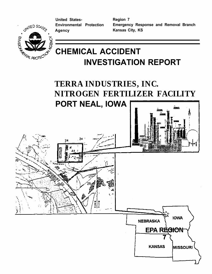
United States- Region 7 Environmental Protection Emergency Response and Removal Branch Agency Kansas City, KS CHEMICAL ACCIDENT INVESTIGATION REPORT TERRA INDUSTRIES, INC. NITROGEN FERTILIZER FACILITY PORT NEAL, IOWA
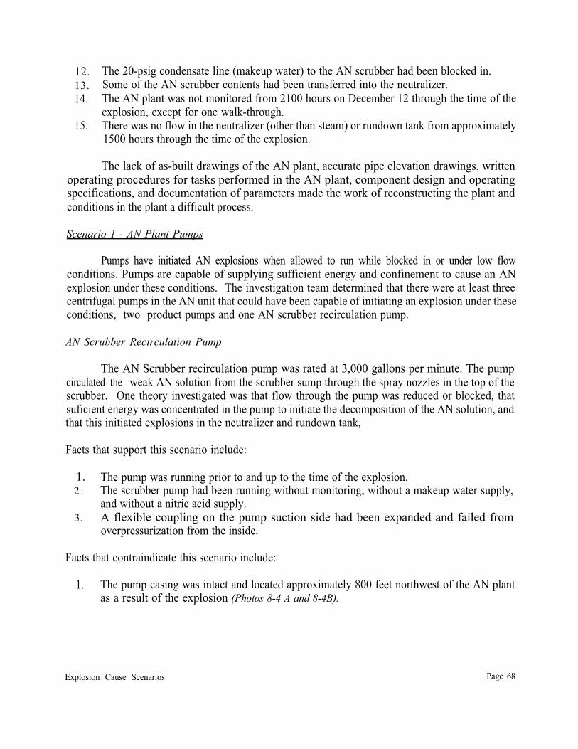
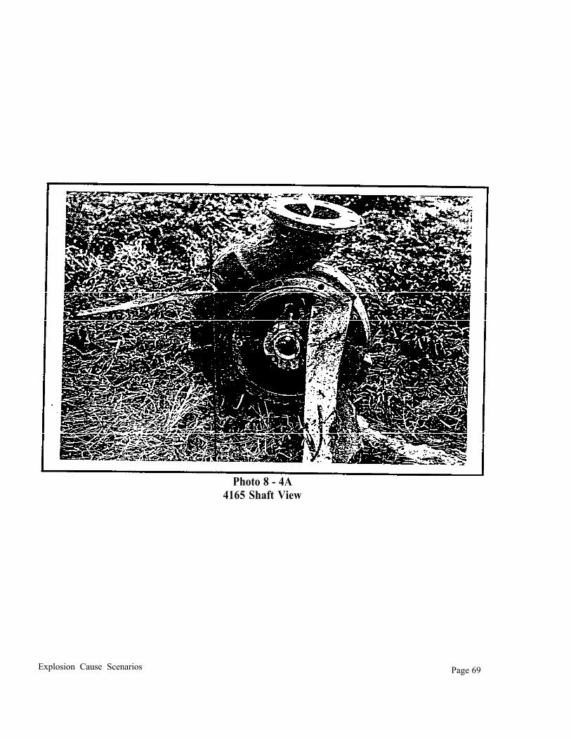
Transcript
United States- Region 7 Environmental Protection Emergency Response and Removal Branch Agency Kansas City, KS
CHEMICAL ACCIDENT INVESTIGATION REPORT
TERRA INDUSTRIES, INC. NITROGEN FERTILIZER FACILITY PORT NEAL, IOWA
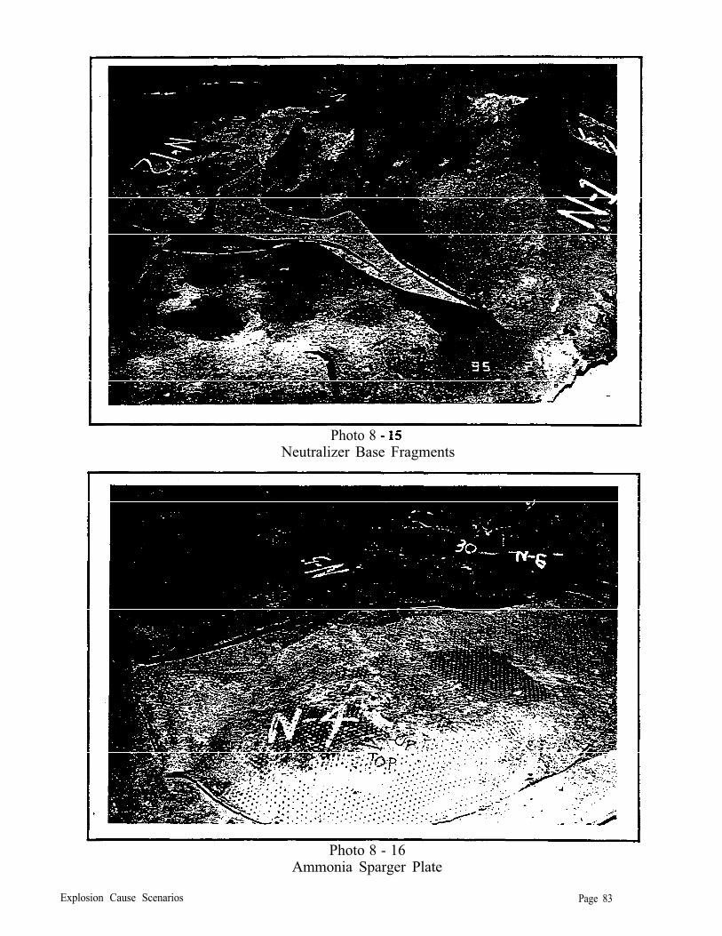
TERRA CHEMICAL ACCIDENT INVESTIGATION REPORT TABLE OF CONTENTS
SECTION 1: EXECUTIVE SU M M A R Y . . . . . . . . . . . . . . . . . . . . . . . . . . . . . . . . . . . . . . . . . l
Mark J. Thomas, Ph.D. -- Team Leader On-Scene Coordinator, U.S. EPA
Alan Cummings - Codes and Emergency Response Specialist Dynamac Corporation
Mariano Gomez, EIT, MBA -- Chemical Engineer Technical Assistance Team, Ecology and Environment
Technical Consultants
W. J. Bradford, PE -- Loss Prevention Expert
Rudolph B. Spanholtz -- NACE Certified Metallurgist St. Louis Testing Laboratories
Angel Salinas -- Drafting and Graphics Technical Assistance Team, Ecology and Environment
iv
Glossary of Terms and Acronyms
AN Ammonium nitrate.
Blocked in A phrase indicating that a piece of process equipment has been isolated from the rest of the process, usually by closing valves leading into and away from the equipment.
Blowdown Transferring AN solution from the scrubber into the neutralizer.
CAS# Chemical abstract service number (also CASN).
DCS Distributed control system.
Hot work permit A written permit that is required before personnel can conduct maintenance or other activities that could provide an ignition source. Examples are welding and grinding.
Offgas A gaseous byproduct of some urea production plants that typically contains ammonia, carbon dioxide and steam.
Prilling A process in which a hot, concentrated liquid is dropped in a countercurrent flow of heated air to solidify the liquid drops into solid spheres.
Turnaround A scheduled maintenance period when an entire plant or facility is shut down for maintenance.
Sparger Device used to uniformly introduced a fluid into a second body of fluid
V
SECTION 1: EXECUTIVE SUMMARY
At approximately 0606 hours on December 13, 1994, an explosion occurred in the ammonium nitrate plant at the Terra International, Inc., Port Neal Complex. Four persons were killed as a direct result of the explosion, and 18 were injured and required hospitalization. The explosion resulted in the release of approximately 5,700 tons of anhydrous ammonia to the air and secondary containment, approximately 25,000 gallons of nitric acid to the ground and lined chemical ditches and sumps, and liquid ammonium nitrate solution into secondary containment. Off site ammonia releases continued for approximately six days following the explosion. Chemicals released as a result of the explosion have resulted in contamination of the groundwater under the facility.
The U. S. Environmental Protection Agency (EPA) Region VII was directed by EPA Headquarters to conduct an investigation to determine the cause of the explosion and to develop recommendations that would help prevent future similar occurrences in ammonium nitrate production facilities. This report contains conclusions reached by the EPA chemical accident investigation team regarding the cause of the explosion at the Terra International, Inc., Port Neal Complex that occurred on December 13, 1994, and recommendations for preventing future similar occurrences in ammonium nitrate facilities. This report is the culmination on ten months of work by EPA’s investigation team. The investigation was conducted principally by EPA On-Scene Coordinator (OSC) Mark Thomas,
Alan cummings, Dynamac Corporation; and Ecology and Environment, Inc. Both Dynamac Corporation and Ecology and Environment, Inc , are EPA contractors. Dr. Thomas and Mr. Cummings participated in EPA’s response activities at Terra that included assistance in air monitoring, chemical stabilization oversight. and tank integrity assessment.
Once the emergency situation had been stabilized, the investigation team began the process of gathering information, conducting interviews and depositions, and attempting to determine the cause of the December 13 explosion. Some of the documents EPA attempted to obtain were destroyed in the explosion, some did not exist, and others did not reflect the construction or operation of the ammonium nitrate plant at the time of the explosion. In large part, piecing together the events leading up to the explosion was done by talking to Terra employees about what was going on in the hours, days, and in some cases, months prior to the explosion. Repetitive interviews were necessary to:
1. Reconstruct reasonably accurate drawings of the plant because of the lack of current drawings provided by Terra; and
2. Identify operating procedures used in the ammonium nitrate plant that were not written procedures.
Investigation team conclusions were reviewed by scientists and engineers before the report was released. Multiple reviews were conducted to ensure that conclusions were reasonable based upon the information gathered during the investigation.
The investigation team concluded that the explosion resulted from a lack of written, safe
Executive Summary Page 1
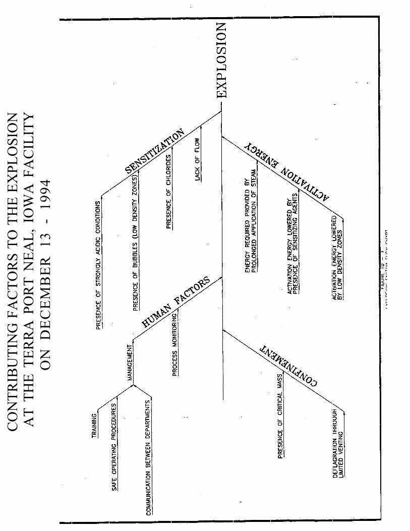
operation procedures at the Terra Port Neal ammonium nitrate plant. The lack of safe operating procedures resulted in conditions in the plant that were necessary for the explosion to occur. The significant conditions that caused the explosion were:
1. Strongly acidic conditions in the neutralizer and rundown tank; 2. Prolonged application of 200 psig steam to the neutralizer nitric acid spargers; 3. The creation of bubbles and low density zones in the neutralizer; 4. Lack of flow in the neutralizer and rundown tank; 5. The presence of chlorides in the neutralizer and rundown tank; and 6. Lack of monitoring of the ammonium nitrate plant after the plant was shut down with the
process vessels charged.
No process hazards analysis had been completed on the ammonium nitrate plant, and interviews with Terra personnel indicated that they were not aware of many of the hazards of ammonium nitrate. The two conditions identified by Terra personnel as concerns were oil contamination of ammonium nitrate and excess heating of ammonium nitrate. No one engineer was assigned responsibility for overseeing operation of the ammonium nitrate plant and reviewing operating procedures in the plant or procedures that might impact the ammonium nitrate plant.
Information gathered during the investigation indicated that overall communications and working relationships were poor between operations and engineering personnel. In the months preceding the explosion, the ammonium nitrate plant was converted to a distributed control system, (DCS). The engineers involved in hooking up the DCS communicated very little with most operators, and some of the operators felt very uncomfortable with the new system once it was up and running. They stated that they had received very little training on operation of the AN plant with the DCS system.
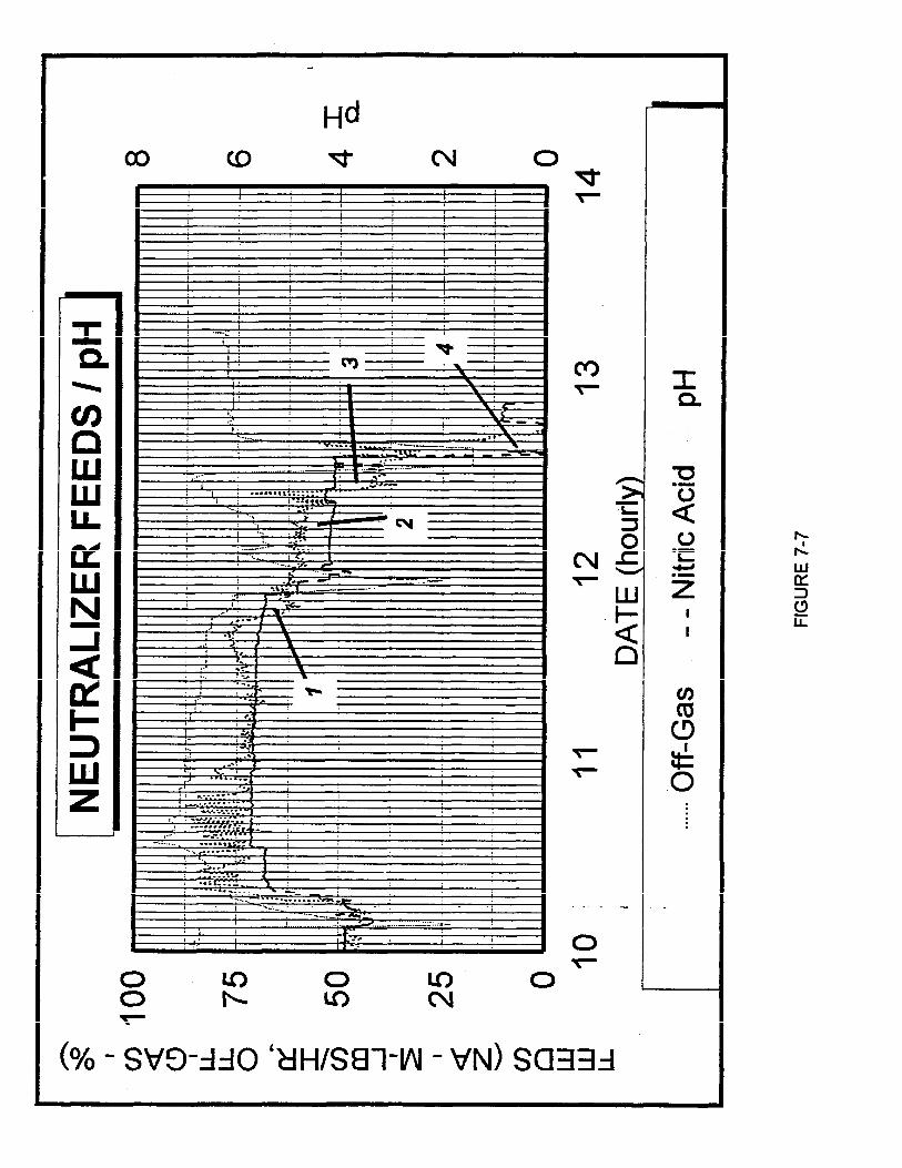
In the days and weeks just prior to the explosion, the equipment failures and maintenance problems were chronic. The pH probe in the neutralizer rundown line appeared to be malfunctioning and there were no spares in stock. Both the ammonium nitrate product pumps which transports ammonium nitrate to storage were leaking or otherwise malfunctioning. There were numerous problems in the nitric acid plant, and maintenance was having a hard time keeping up with the repair requests.
From interviews with Terra employees, no one believed that oil contamination could have gotten into the ammonium nitrate plant and sensitized the ammonium nitrate, even though large amounts of oil had been lost upstream in the ammonia plant. Terra did not monitor ammonium nitratefeedstreams for contaminant presence. Chloride contamination of the nitric acid had not been analyzed since 1980; although the nitric acid plant is a logical source of chloride contamination. Terradid not periodically monitor feed streams into the ammonium nitrate unit for contamination.
The investigation team developed recommendations to reduce the likelihood of future similar occurrences in ammonium nitrate plants.The detailed information that led to these recommendations is included in the report. The recommendations are that facility management, with the involvement
Executive Summary Page 2
of engineers, operators and maintenance personnel:
1. Conduct a thorough, formal process hazard analysis (PHA) of the ammonium nitrate process according to industry guidelines and practices. Current process safety information including piping and instrumentation diagrams, plant drawings, process chemistry, chemical hazard information and expertise in the technique used are necessary to conduct this evaluation.- The findings and recommendations generated by the PHA should be promptly addressed and resolved and should address modifications, safeguards or controls to eliminate, reduce or manage chemical and process hazards.
2. Establish safe operating parameters for all activities in the ammonium nitrate process based on the PHA. Parameters for this plant should at least include pH, temperature, and acceptable contaminant levels.
3. Develop, implement and keep up-to-date written safe operating procedures for all operations and activities, including normal startups, normal and emergency shutdowns or idling and routine operation of the ammonium nitrate unit. These written procedures should be based on the PHA and require that critical process parameters identified above be monitored and specify actions to be taken when parameters deviate from acceptable ranges.
4. Develop a management of change process for all changes in process equipment, procedures and operating parameters or ranges in the ammonium nitrate unit.A prestartup safety review should be conducted prior to operation using changed equipment, procedures or parameters.
5. Develop a program to maintain the on-going mechanical integrity of the ammonium nitrate unit. Facility management should consider use of predictive failure analyses and aggressive preventive maintenance systems as part of their mechanical integrity program.
6. Develop and implement training programs on operating and maintenance procedures for operators and maintenance personnel involved in the ammonium nitrate unit.
7 . Ensure that management, engineers, operators and maintenance personnel develop lines of communication to ensure that these recommendations are implemented and maintained. Theinvestigation team further recommends that corporate management monitor facility performance in implementing these programs and conduct periodic audits to ensure program effectiveness.
8. Share information on the hazards of the substances handled, the prevention measures in-place or planned to prevent accidental releases and the emergency response measures to be taken for the ammonium nitrate unit with the State Emergency Response Commission (SERC), Local Emergency Planning Committee (LEPC), first responders, and the public surrounding the facility.
These recommendations reflect accidental release prevention requirements contained in the
Executive Summary Page 3
OSHA Process Safety Management (PSM) regulations and in current industry guidelines and practices for prevention of chemical accidents and emergencies. EPA also intends to build on the OSHA PSM requirements and is currently considering how best to capture these recommended practices in the Risk Management Programs for Chemical Accidental Release Prevention rule to promulgated in March 1996.
Executive Summary Page 4
SECTION 2: BACKGROUND
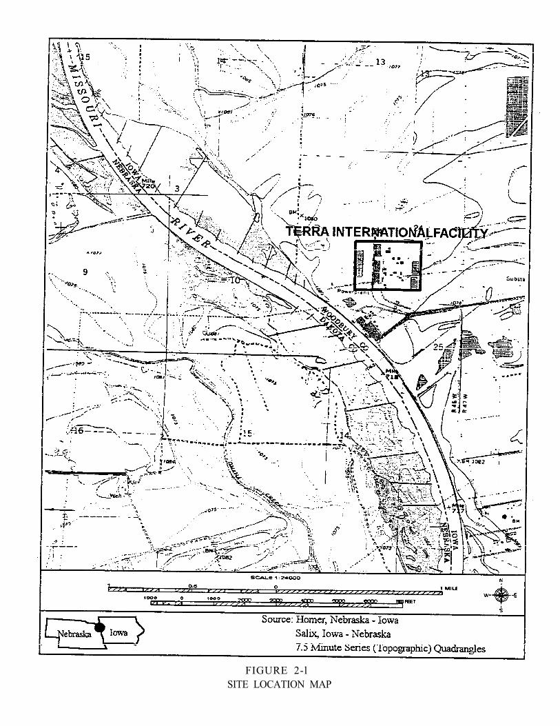
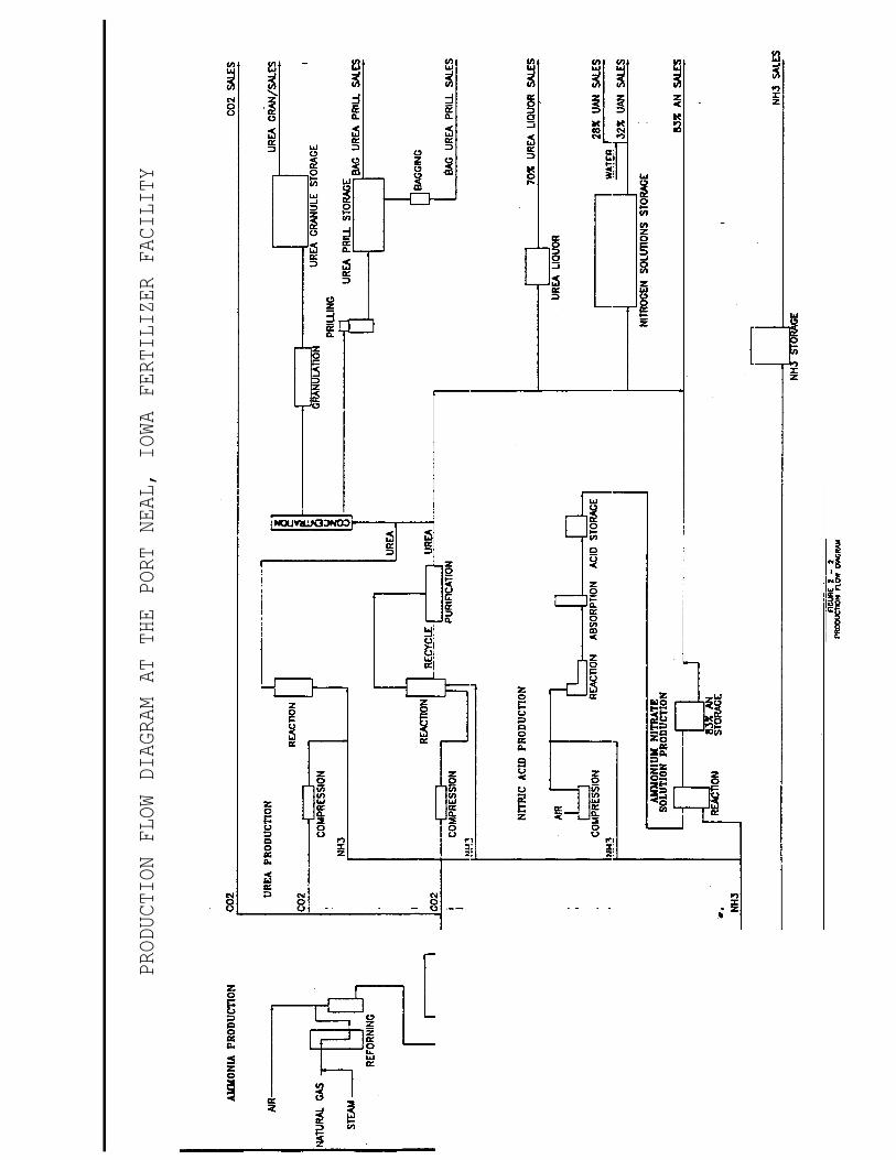
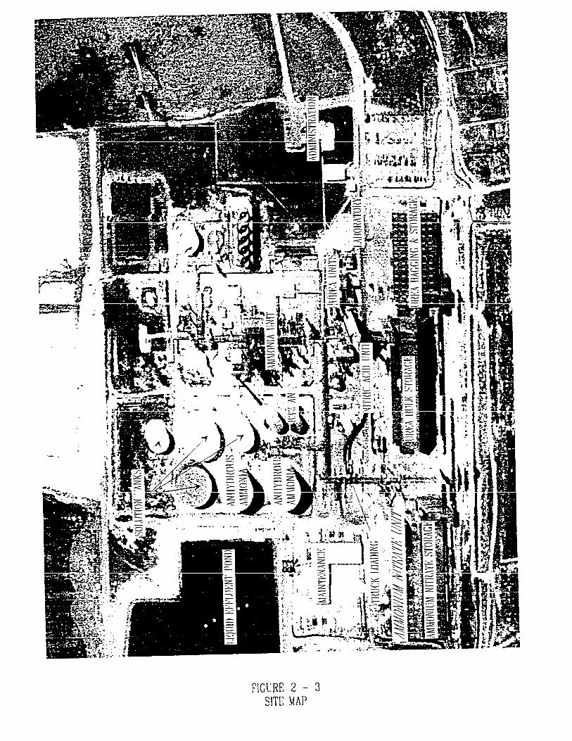
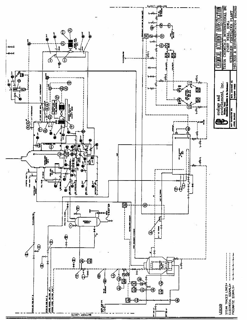
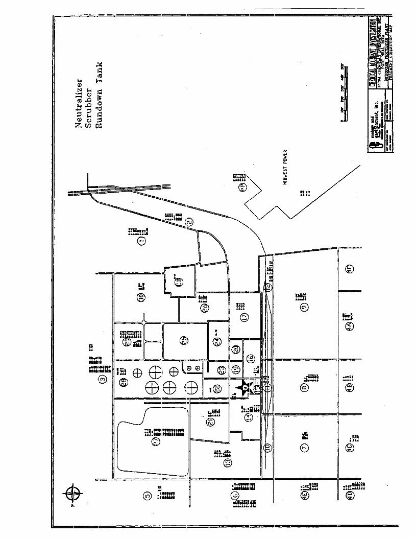
The Terra Industries, Inc., Port Neal Complex is a nitrogen products facility located in the western portion of Woodbury County, Iowa. The facility is located in a primarily rural area containing some industry, in Section 24 of the Liberty Township, Woodbury County, Iowa (Figure2-1). The major activities at the Port Neal Complex include the synthesis of anhydrous ammonia, operation of a nitric acid plant, and urea and ammonium nitrate production (Figure 2-2). The plant is composed of two major areas. Area I consists of the ammonia plant, tank farm, and utilities (Figure 2-3). Area II consists of the nitric acid plant, the urea plants, and the ammonium nitrate plant.
The ammonia plant manufactured ammonia from methane, water, and air. Carbon dioxide was recovered as a by-product of ammonia production. Ammonia was transferred to storage for sale, to the nitric acid plant for nitric acid production, to the urea plant for urea production, and was available to the ammonium nitrate plant for ammonium nitrate production.
The nitric acid plant oxidized ammonia in air in the presence of a precious metal gauze to produce 55%-56% nitric acid. The nitric acid was transferred to a storage tank and was subsequently used as a raw material in the ammonium nitrate plant.
The three urea plants at the Terra facility produced urea solution and urea prills from ammonia and carbon dioxide. A by-product of two of the urea plants. Offgas, contained primarily ammonia, carbon dioxide, and steam. This offgas was transferred to the ammonium nitrate plant as an ammonia source during normal ammonium nitrate plant operations
The ammonium nitrate plant produced an 83% ammonium nitrate (AN) solution by reacting ammonia and nitric acid in a vessel called a neutralizer. The nitric acid plant supplied the nitric acid. Urea plant offgas supplied the ammonia for normal operations. The AN plant could also use ammonia stored in two pressurized storage vessels (bullet tanks) and ammonia from storage. The AN solution was sold or mixed with urea to form a urea-ammonium nitrate solution.
Terra Industries, Inc., has owned and operated the Port Neal Complex since its original construction beginning in 1965. The facility began manufacturing activities in late 1967. Terra built the facility with the intent of providing agricultural chemical users within a 200 mile radius of the facility with ammonia and other nitrogen crop chemicals. The facility shipped approximately 70% of the manufactured nitrogen products from the facility by truck, and the balance by rail. The Urea II process was added to facility operations in 1974, with major modifications in 1978. Terra replaced the original C&I Girdler neutralizer in the ammonium nitrate plant with a Mississippi Chemical Corporation neutralizer in 1980.
A major modification of the ammonia plant that included the installation of a Honeywell TDC-3000 distributed control system (DCS) and process equipment upgrades was completed in 1992. The replacement of process equipment increased the ammonia process capacity from 800 tons per day (TPD) to 1,000 TPD. An ammonia scrubber and a Honeywell TDC3000 distributed control system
Background Page 5
FIGURE 2-l SITE LOCATION MAP
PROD
UCTI
ON FL
OW DI
AGRA
M AT
TH
E PO
RT NE
AL,
IOWA
FE
RTIL
IZER
FA
CILI
TY
were added to the ammonium nitrate plant during the facility turnaround conducted in September 1994. Future references to the ammonia scrubber will be as the AN scrubber.
The Port Neal Complex comprises approximately 70 acres. Finished products at this facility include anhydrous ammonia, ammonium nitrate, urea, and urea ammonium nitrate solution. Finished products are sold primarily to wholesale distributors. Raw materials included natural gas, water, and air. Material transportation to and from the facility included highway, rail, and pipeline conveyances. The facility was staffed 24 hours per day with a minimum of two shift supervisors and eight operators. The facility employed approximately 100 persons.
The U. S. Environmental Protection Agency (EPA) Region VII conducted a chemical safety audit (CSA) on the ammonia synthesis process in the ammonia plant at the Port Neal Complex in February 1994, as a result of a reported 600-pound ammonia release that occurred on February 24, 1993. The chemical safety audit was conducted by a team of engineers and emergency response specialists. The CSA team reviewed documents provided by Terra that were representative of ammonia plant activities in the areas of operations, maintenance, and process safety. The audit provided a snapshot of conditions that existed in the ammonia plant at the time of the audit, and did not reflect planned or anticipated changes in the plant. The resulting audit team recommendations were not mandatory. The CSA team did not conduct follow up inspections to determine whether or not any changes were made by Terra pursuant to the audit team recommendations. The CSA was conducted with the full and voluntary cooperation of Terra Industries, Inc., corporate and facility management.
At approximately 0606 hours on the morning of December 13, 1994, an explosion occurred at the Terra Port Neal Complex within the ammonium nitrate plant. Four persons were killed and 18 persons were hospitalized as a result of the explosion. Initial reports indicated that the explosion had occurred in the ammonium nitrate plant. Prior to the explosion, the ammonium nitrate plant had been shut down because of a nitric acid shortage and had remained shut down until the explosion. The nitric acid plant had been shut down since approximately 0500 hours on December 12, and Terra was in the process of starting up the acid plant when the explosion in the AN plant occurred.
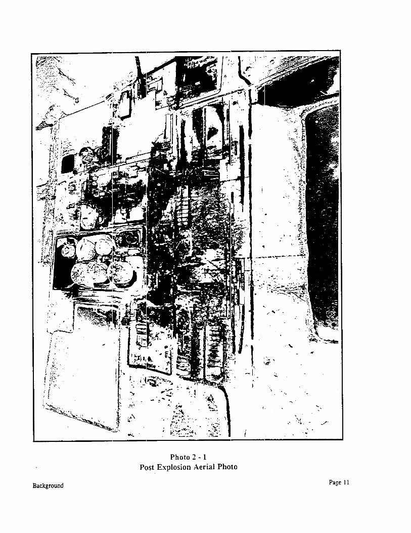
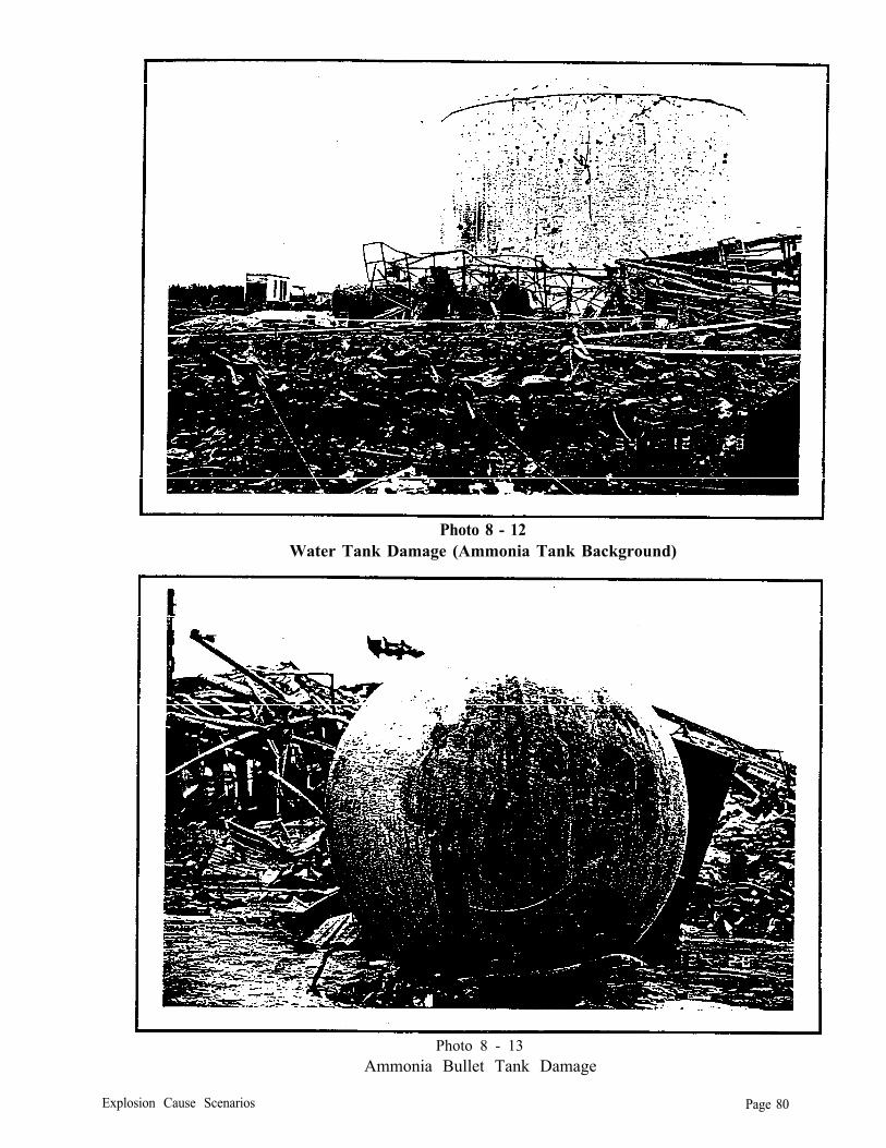
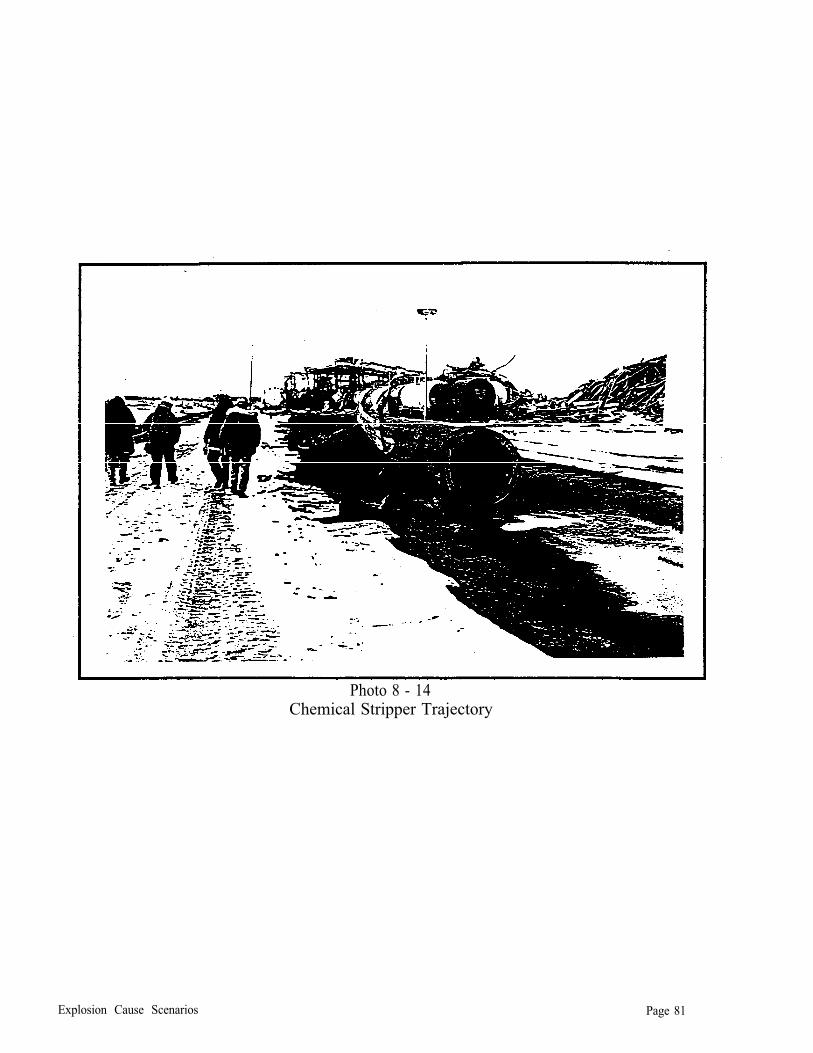
The explosion caused extensive damage to the Terra facility and resulted in the release of approximately 5,700 tons of anhydrous ammonia into the atmosphere and on the ground throughout the facility before the emergency phase of the resulting response was completed on December 19, 1994 (photo 2-1). Plumes and clouds of varying ammonia concentrations were monitored as far as five miles from the facility. Approximately 25,000 gallons of nitric acid were released from a damaged storage tank into lined chemical ditches and sumps on the facility.
U.S. EPA Region VII responded to an Iowa Department of Natural Resources’ (IDNR) request for assistance during the emergency phase of the incident. EPA on-scene coordinators assisted IDNR by conducting air monitoring off site, conducting limited air monitoring at the Terra facility, entering areas of the Terra facility where chemicals had been released to assess the extent of release and assess the integrity of remaining chemical storage tanks, responding to citizen complaints of air quality problems, providing photo-documentation of site activities, and assisting with oversight
Background Page 9
of response and recovery activities performed by Terra personnel and contractors. EPA personnel and contractors worked closely with the local government incident commander to ensure that public safety issues were addressed in a comprehensive and timely manner.
At the conclusion of the emergency response, EPA Region VII was directed to conduct an investigation to determine the cause of the explosion at the Terra facility and to develop recommendations in an effort to prevent future similar occurrences in ammonium nitrate production facilities. The investigation was conducted pursuant to authorities contained in the Comprehensive Environmental Response, Compensation and Liability Act (CERCLA), as amended by the Super-fund Amendment and Reauthorization Act (SARA) of 1986, 42 U.S.C. §9601 et seq., and the Clean Air Act (CAA) as amended by the Clean Air Act Amendments of 1990, 42 U.S.C. §7401 et seq.
Background Page 10
SECTION 3: CHEMICAL ACCIDENT INVESTIGATION OVERVIEW
On December 19, OSC Mark Thomas, U. S. EPA Region VII, was assigned by EPA Headquarters to conduct an investigation into the cause of the explosion. The purpose of the investigation was to determine, if possible, the cause of the explosion and to develop a list of recommendations to help prevent future similar occurrences. The investigation included numerous trips to Sioux City/Port Neal, Iowa, as well as to other ammonium nitrate production facilities to gather information. The investigation was conducted under authorities contained in CERCLA, Section 104, 42 U.S.C. 9604 and the CAA Section 114, 42 U.S.C. 7414, Section 112R.
Independent investigations to determine the, cause of the explosion were conducted concurrent to the EPA investigation by Iowa OSHA, Iowa Fire Marshal, and Terra Employees along with Wilfred E. Baker Engineering (retained by counsel for Terra).
Terra employees advised the investigation team at the beginning of the investigation that all information provided to the EPA investigation team and all photographs taken of the Terra Port Neal facility, equipment and debris were confidential business information (CBI). All materials provided to EPA by Terra pertaining to this investigation were handled as CBI. Terra reclassified much of the material provided to the investigation team to a non-confidential status in August 1995.
The investigation team advised Terra personnel at the onset of the investigation that the investigation would be conducted to determine the cause (or possible causes) of the explosion, identify circumstances that facilitated the explosion, and to develop recommendations to help avoid future similar occurrences. Terra personnel were advised that the investigation would be conducted, to the extent possible, in a manner so as to minimize any interruption of Terra’s recovery and investigation activities. To avoid unnecessary duplication of effort, Terra agreed to share information obtained during the investigation. The investigation team further advised Terra that, if warranted, EPA may pursue enforcement actions.
The initial investigation included a visual overview of the Terra facility and surrounding areas to determine the area of origin of the explosion, gathering information specific to the ammonium nitrate (AN) plant design specifications, and gathering information about plant operations and maintenance for a period of at least seven days preceding the explosion. The initial phase included viewing physical evidence in and around the facility and requesting technical, operating and maintenance information from Terra. The investigation team determined that recent changes in the AN plant included the addition of a AN scrubber and the implementation of a Honeywell distributed control system (DCS). Investigation activities included analyzing the impact of these items on normal AN plant operations.
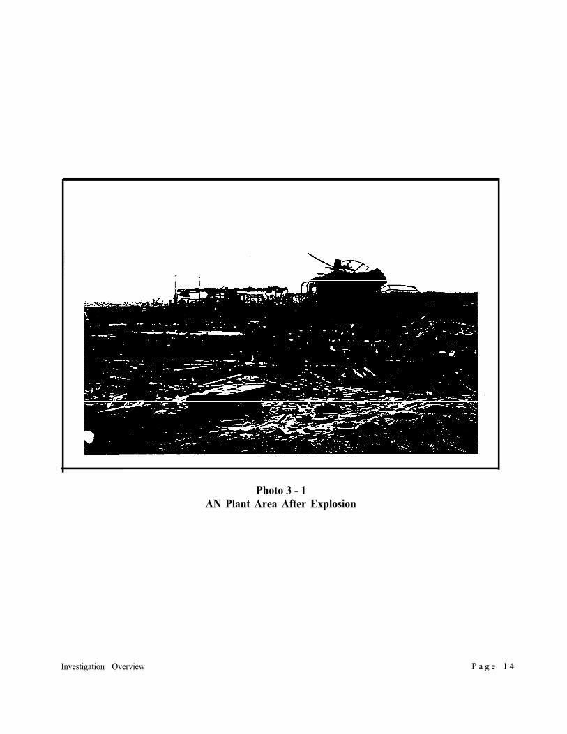
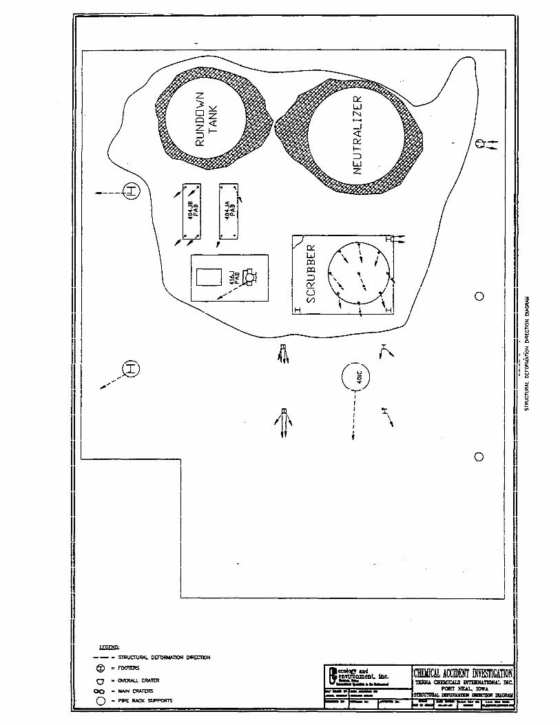
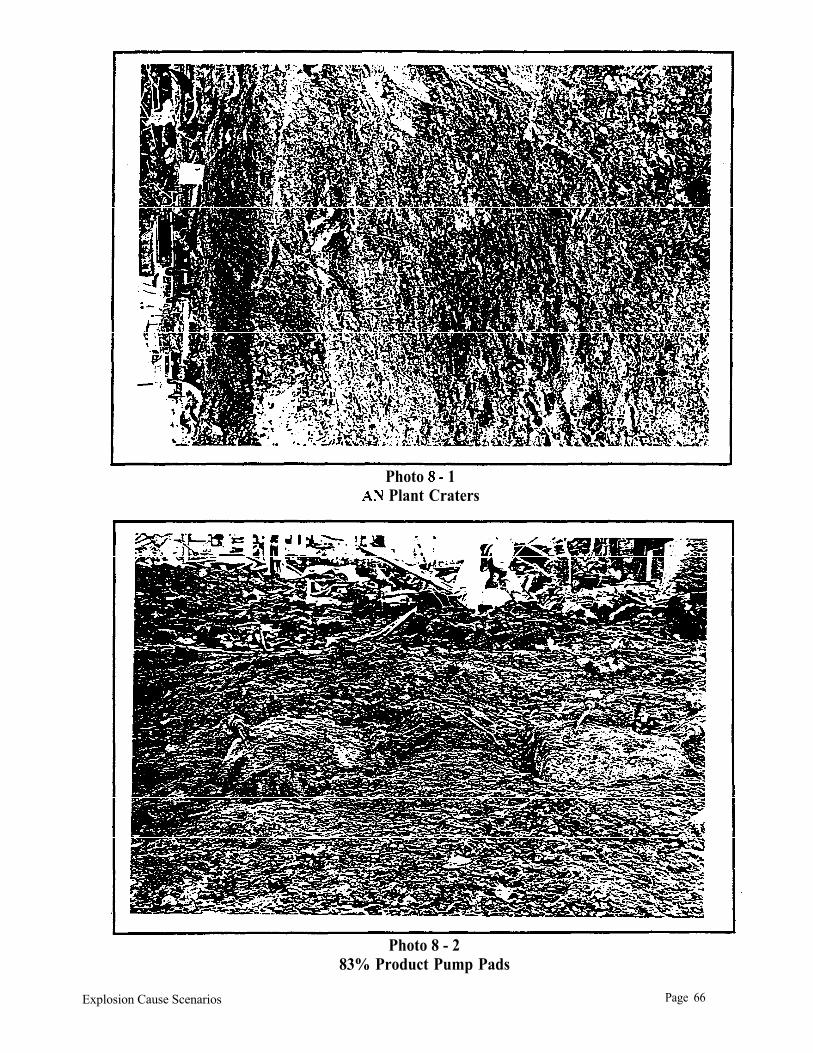
Initial site investigation included sketching and photographing the Terra facility to determine the location of the explosion(s) and photographing explosion debris and damage to facilities off site. Initial observations included sketching collateral damage patterns to determine the location of the explosion(s). The investigation team concluded that more than one explosion occurred in the area identified by Terra personnel as the AN plant. Craters in this area were located in the AN plant at
Investigation Overview Page 12
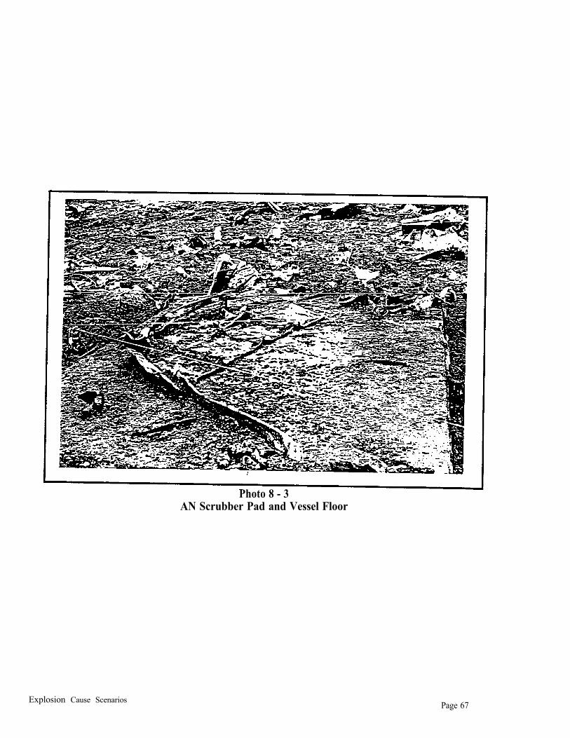
locations identified by Terra personnel as previous locations of the AN neutralizer and the AN 83% rundown tank (photo 3-1). The presence of at least two distinct craters indicated that more than one explosion occurred in the AN plant. Investigators measured and sketched the area of explosion origin, approximate crater dimensions, and the resulting directions in which remaining steel, reinforcing bar and bolts were positioned (Figure 3-1). Other site documentation activities included visits to the forensic warehouse to view critical process vessel pieces that had been recovered, identified and assembled by Baker Engineering personnel.
Investigation activities included the request of numerous documents from Terra to reconstruct activities and events at the Terra Port Neal facility for a period of one week prior to the explosion as well as maintenance activities for a period of one year before the explosion. The purpose of this activity was to identify actions and conditions that may have led to the explosion in the AN plant. Documents requested from Terra on December 28, 1994 included:
1. Current drawings of the AN plant that showed equipment locations, piping location and elevations, process vessel construction, and the most current piping and instrumentation diagram (P&ID). These drawings were requested before and after the installation of the AN scrubber.
2. The equipment history records for the process vessels and active components in the AN plant and maintenance records for the AN plant for a period of one year. This request included all hot work permits issued for a period of one week before the explosion.
3. Operator logs and distributive control system records for the AN plant for a period of one week before the explosion.
4. The management of change file for the addition of the AN scrubber to the AN plant.
5. Copies of all written standard operating procedures for the AN plant for startup, normal operation, normal shutdown, emergency shutdown, and turnaround activities.
6. All completed checklists for activities in the AN plant,
Other written requests for additional documents were submitted as the investigation progressed.
The investigation team conducted a series of interviews and depositions of Terra employees that included plant management personnel, engineers, operators, supervisors, and maintenance personnel.Interviews and depositions were conducted at the Terra Port Neal facility, Terra Corporate offices in Sioux City, Iowa, Woodbury County Emergency Services offices in Climbing Hill, Iowa, and at EPA Region VII Headquarters in Kansas City, Kansas. These interviews focused on Terra policies and procedures for AN plant operations and clarification of events and conditions at the Terra Port Neal facility prior to the explosion. The investigation team conducted interviews with BECO Engineering personnel pertaining to the design, installation and operation of the AN scrubber at the Terra Port Neal facility. The investigation team also interviewed management, maintenance and
Investigation Overview Page 13
Photo 3 - 1 AN Plant Area After Explosion
Investigation Overview P a g e 1 4
operations personnel at other facilities producing 83% ammonium nitrate solutions to determine any additional information pertaining to the known hazards of manufacturing, transferring, and storage of AN solutions; and to determine how persons at other AN production facilities avoided or mitigated those identified hazards. The investigation team interviewed personnel form some of the contractors who had performed work at the Terra facility within one year prior to the explosion.
The EPA investigation team utilized contractors and agency employees for consultation pertaining to the chemical and physical properties of ammonium nitrate, analysis of facts obtained by the investigation team, and assistance in the development of conclusions based on those facts. Thisexpertise included chemical and metallurgical analysis of process vessel fragments.
The investigation team and consultants prepared an initial draft of the technical sections of this report and submitted the report for two distinct review phases. The first phase was a scientific review of the conclusions and the evidence supporting the conclusions. A panel consisting of EPA scientists and engineers from Region VII and the Office of Research and Development (ORD) reviewed the data gathered by the investigation team and evaluated the conclusions contained in the report for accuracy. The second phase consisted of a final review by EPA personnel from Region VII and Headquarters.
The results of the investigation are contained in Section 9 of this report.
Investigation Overview Page 16
SECTION 4: AMMONIUM NITRATE (AN) INFORMATION
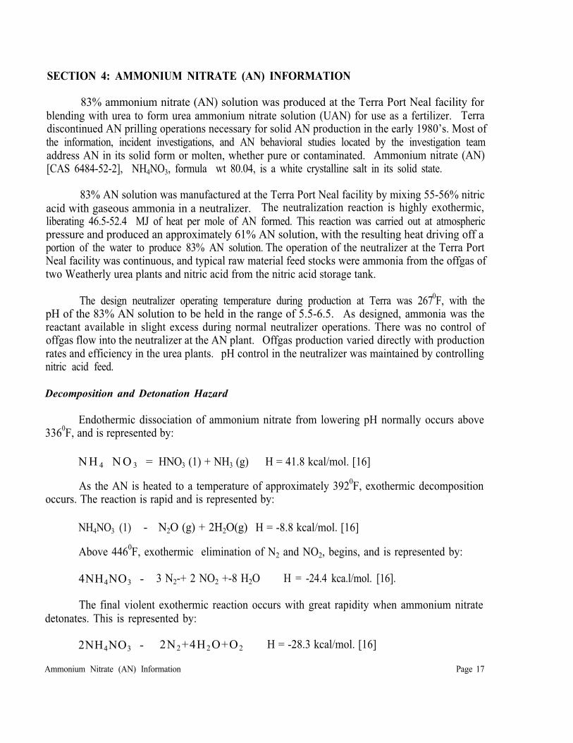
83% ammonium nitrate (AN) solution was produced at the Terra Port Neal facility for blending with urea to form urea ammonium nitrate solution (UAN) for use as a fertilizer. Terradiscontinued AN prilling operations necessary for solid AN production in the early 1980’s. Most of the information, incident investigations, and AN behavioral studies located by the investigation team address AN in its solid form or molten, whether pure or contaminated. Ammonium nitrate (AN) [CAS 6484-52-2], NH4NO3, formula wt 80.04, is a white crystalline salt in its solid state.
83% AN solution was manufactured at the Terra Port Neal facility by mixing 55-56% nitric acid with gaseous ammonia in a neutralizer. The neutralization reaction is highly exothermic, liberating 46.5-52.4 MJ of heat per mole of AN formed. This reaction was carried out at atmospheric pressure and produced an approximately 61% AN solution, with the resulting heat driving off a portion of the water to produce 83% AN solution. The operation of the neutralizer at the Terra Port Neal facility was continuous, and typical raw material feed stocks were ammonia from the offgas of two Weatherly urea plants and nitric acid from the nitric acid storage tank.
The design neutralizer operating temperature during production at Terra was 2670F, with the pH of the 83% AN solution to be held in the range of 5.5-6.5. As designed, ammonia was the reactant available in slight excess during normal neutralizer operations. There was no control of offgas flow into the neutralizer at the AN plant. Offgas production varied directly with production rates and efficiency in the urea plants. pH control in the neutralizer was maintained by controlling nitric acid feed.
Decomposition and Detonation Hazard
Endothermic dissociation of ammonium nitrate from lowering pH normally occurs above 3360F, and is represented by:
N H 4 N O 3 = HNO3 (1) + NH3 (g) H = 41.8 kcal/mol. [16]
As the AN is heated to a temperature of approximately 3920F, exothermic decomposition occurs. The reaction is rapid and is represented by:
The final violent exothermic reaction occurs with great rapidity when ammonium nitrate detonates. This is represented by:
2NH4NO3 - 2N2+4H2O+O2 H = -28.3 kcal/mol. [16]
Ammonium Nitrate (AN) Information Page 17
Ammonium nitrate is normally classified as an oxidizing agent. The pure salt is not classed as an explosive because it is difficult to detonate. Spark, flame, or friction normally do not cause detonation in solid AN, and it is relatively insensitive to shock. However, a variety of substances, such as chloride and oil, are known to sensitize the material [16].
When used in blasting, AN is mixed with fuel oil, and sometimes sensitizers such as powdered aluminum. Lower density AN is preferred for explosive formulation because it absorbs the oil more effectively. When detonated, these mixtures have an explosive power of 40% to 50% of TNT.
Ammonium Nitrate Sensitization
Information collected by the investigation team indicated that the energy necessary to initiate thermal decomposition decreased if the AN was sensitized. Conditions that can sensitize AN and increase the hazards of thermal decomposition, deflagration and detonation are as follows:
1. Concentration - Literature reviewed by the investigation team indicated that past AN explosions have occurred on solid product or in solutions with concentrations greater than 95% [18]. However, violent decomposition reactions of AN solutions have been documented with concentrations as low as 80% ammonium nitrate by weight in water [42].
2. pH - As AN becomes more acidic, AN stability decreases [1,2]. Free acid in AN solution is a significant source of or a contributing factor to AN solution decomposition.
3. Temperature - Increased temperatures can result in increased sensitivity. Reduced temperatures can result in AN crystallization (salting out), and solid AN may be less difficult to initiate than the 83% AN solution [12,13,14,21].
4. Contamination - AN contaminated with organic materials is more easily detonated [ 14]..
Inorganic contaminants also sensitize AN and include chlorides and some metals, such as chromium, copper, cobalt and nickel [3, 5, 6, 14, 21, 42]. These contaminants reduce the energy required to initiate a critical ammonium nitrate decomposition reaction.
Chlorides react synergistically with some metals to further reduce energies needed to initiate thermal decomposition. Studies reviewed by the investigation team concluded that synergistic catalysis with chloride generally requires a metal capable of forming chloro complexes of reasonable stability in two oxidation states differing by one electron unit, and at the same time are capable of forming chloro complexes of moderate stability in these states. Chromium was considered a special case because oxo complexes were believed to be involved.
Metals that react synergistically with chlorides to further reduce thermal decomposition reaction temperatures include chromium, copper, silver, nickel, iron, palladium, gold, cerium, and cobalt.
Ammonium Nitrate (AN) Information Page 18
Other sensitizing materials include hypophosphites and thiosulfates.
5. Confinement - The higher the degree of confinement, the greater the possibility of deflagration/detonation. The degree of confinement necessary to support detonation decreases, as the presence of other sensitizing factors increase. The mass of the ammonium nitrate may create sufficient confinement if the AN is sufficiently sensitized and the threshold temperature for thermal decomposition is reached [21].
6. Low density areas - Low density pockets in the ammonium nitrate melt, such as gas bubbles, reduce the energy required to initiate decomposition reactions [1, 23, 24]. Bubbles also enhance thermal decomposition propagation in the ammonium nitrate solution through adiabatic compression as the decomposition pressure wave moves through the media, generating temperatures as high as 2,000oF.
Safe Practices for Manufacturing and Storage of Ammonium Nitrate
Safety documents reviewed by the investigation team that dated from the 1950s and 1960s provide the following recommendations for the safe manufacturing and handling of ammonium nitrate [14, 17]:
1 . Contamination of ammonium nitrate with combustibles and catalysts must be avoided.
2. Confinement must be avoided and free ventilation of gaseous products must be possible.
3. All processes for the manufacture of ammonium nitrate involve handling concentrated solutions of the salt and particular care is required in these stages of the manufacturing process. The decomposition of the molten salt is accelerated by acidic conditions as well as by contamination. These conditions should be avoided, especially in storage.
Publications from the early 1950s warn that chlorides are probably an impurity for which. great precautions should be taken to avoid since they can act as a catalyst of AN thermal decomposition. Chloride sources are identified primarily as nitric acid plants and plant cooling water [ 14]. Action levels based on chloride concentrations range from 1 part per million to 80 parts per million by volume.
4 . Contamination of feedstreams should be anticipated. Feedstreams should be monitored accordingly and procedures developed for these occurrences. Documents also warn of the possibility of operator errors and contamination introduced through maintenance activities and recommend the development of procedures to address these issues.
Investigation Objectives for Determining AN Sensitization
One focus of the investigation was to determine the presence, if any, of sensitizing materials and the extent of any ammonium nitrate sensitization. This resulted in the review of the following:
Ammonium Nitrate (AN) Information Page 19
1. Materials of construction for process vessels, piping, valves and any other component that may have contacted the ammonium nitrate.
2. Events that occurred in the Terra facility that may have introduced sensitizers or sensitizing conditions into the ammonium nitrate.
3. Operating procedures, both written and practiced, in the Terra facility that may have introduced sensitizers or sensitizing conditions into the ammonium nitrate.
4. Analytical data from product and waste samples for the presence of chemical sensitizers.
5. Metallurgical analytical data form process equipment fragments for the presence of chemical sensitizers, forces acting on the metal, temperatures to which fragments were exposed, and metal specifications and ahoy constituents.
Ammonium Nitrate (AN) Information Page 20
SECTION 5: AMMONIUM NITRATE PLANT OPERATIONS
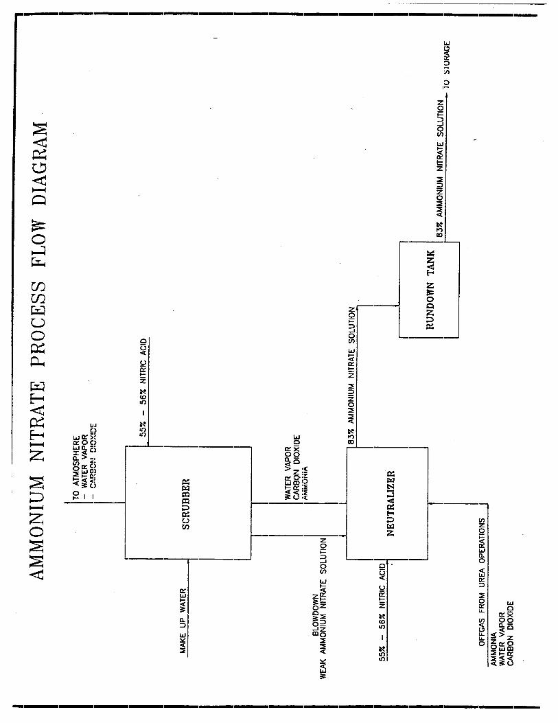
The ammonium nitrate (AN) plant at the Terra Port Neal facility produced 83% ammonium nitrate solution utilizing ammonia and 55-56% nitric acid feedstreams (Figure 5-l). This reaction took place in the neutralizer. The ammonium nitrate solution overflowed from the neutralizer into the rundown tank. The rundown tank was a surge vessel. The 83% ammonium nitrate solution (or melt) was pumped from the rundown tank to one of two storage tanks to be used as an intermediate product in the production of urea ammonium nitrate UAN) solutions and for sale.
Recent additions to the AN plant included conversion from a Fisher control system to a Honeywell TDC-3000 distributed control system (DCS) and the construction and installation of a AN scrubber by BECO Engineering.
Figure 5-2 is a schematic drawing of the Terra ammonium nitrate plant. The investigation team requested plant location and piping elevation drawings as well as a current piping and instrumentation diagram (P&ID) for the AN plant early in the investigation. Terra provided drawings and P&IDs for the original C&I Girdler AN plant constructed in 1966. These drawings did not include the relocation of process equipment that occurred during installation of the Mississippi Chemical neutralizer in 1980 or the AN scrubber in 1994. The most current site location drawings were generated by BECO Engineering for their use in the design and installation of the AN scrubber. The schematic drawing was reconstructed by the investigation team from numerous documents and interviews and was corrected by Terra employees during interviews occurring late in the investigation [ID-1, ID-4, ID-9, ID-14, ID-18, ID-19, ID-21, ID-23].
The major vessels in the ammonium nitrate plant were the neutralizer, rundown tank (Photo5-l), and the scrubber (Photo 5-2).
Neutralizer
The manufacture of 83% AN occurred in the neutralizer (Figure 5-3). Terra constructed the current neutralizer in 1980 after licensing the technology from Mississippi Chemical Corporation, Yazoo City, Mississippi. Terra purchased the neutralizer license to reduce ammonia emissions through the increased efficiency offered in this neutralizer design. Two raw material streams were fed into the neutralizer. Nitric acid was provided by the nitric acid plant. Ammonia was supplied for normal operations in the offgas from two small urea plants. Ammonia was also available from two 30,000-gallon liquid ammonia bullet tanks located south of the AN plant or from the two 5,000,000-gallon atmospheric pressure ammonia storage tanks located in the facility tank farm. The neutralizer was constructed of 304L stainless steel, and the nitric acid spargers were fabricated from titanium.
AN Plant Operations Page 21
Photo 5 Neutralizer and Rundown Tank
AN Plant Operations Page 24 .
Photo 5 - 2 AN Scrubber
AN Plant Operations Page 25
Information provided through interviews indicates that the neutralizer was insulated and steam jacketed when built [ID-11, ID-15]. Insulation consisted of 2 inches of calcium silicate. The steam coils were not connected to a steam header, thus requiring that a flexible steam line be connected between the neutralizer and the steam header for heating. Information gathered during interviews indicated that the steam coils in the neutralizer jacket had corroded and could not be used. No one interviewed could remember using the steam coils in the past several years [ID-1,ID-11 ].
During normal operations, ammonia was introduced into the bottom of the neutralizer at a rate determined by the offgas production of the urea plants. The ammonia flowed through an insulated 14-inch line labeled “ammonia/offgas” on the schematic with an ammonia sparger plate at the line terminus. Nitric acid was introduced into the neutralizer through two titanium spargers located in the lower region of the neutralizer. The spargers discharged nitric acid into the neutralizer. The neutralization reaction of the ammonia and nitric acid is extremely exothermic, with the heat of reaction used to remove excess water to produce the 83% solution. The resulting solution overflowed from the neutralizer through a “rundown” line into the rundown tank.
The Mississippi Chemical neutralizer was designed to operate at a temperature of approximately 265°F in a pH range from 2.0 through 6.5. For reasons of efficiency and ammonia emission reduction, Terra specified that the neutralizer be designed to operate within a pH range of 5.5 - 6.5.
Offgas flow from the urea plants could not be controlled in the AN plant. Nitric acid was controlled by a control valve (FCV-401). The plant design provided for the AN solution pH to be monitored by a pH probe located in the rundown line between the neutralizer and the rundown tank AE-403). The neutralizer contained one temperature sensor (TI-445S). Written communication received from Terra in September 1995, stated the temperature sensor was located in the upper portion of the neutralizer, approximately 18 inches below the overflow. Offgas and nitric acid flows, neutralizer temperature, and rundown pH are indicated and recorded by the AN DCS.
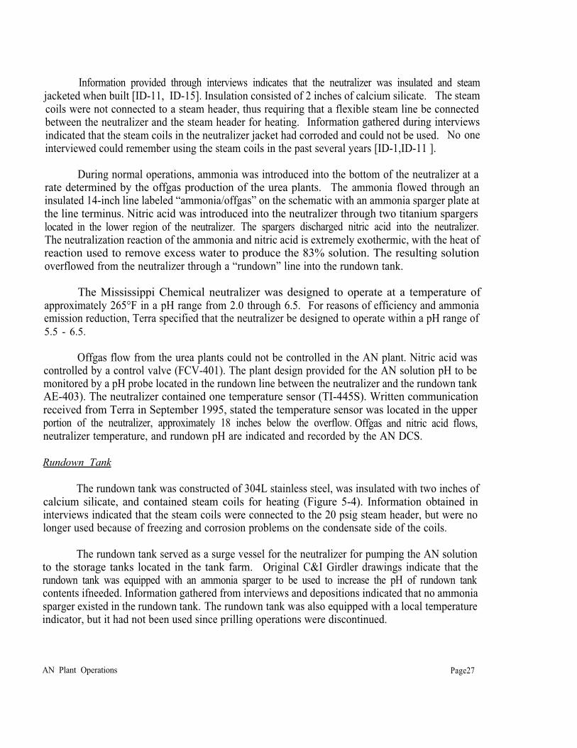
Rundown Tank
The rundown tank was constructed of 304L stainless steel, was insulated with two inches of calcium silicate, and contained steam coils for heating (Figure 5-4). Information obtained in interviews indicated that the steam coils were connected to the 20 psig steam header, but were no longer used because of freezing and corrosion problems on the condensate side of the coils.
The rundown tank served as a surge vessel for the neutralizer for pumping the AN solution to the storage tanks located in the tank farm. Original C&I Girdler drawings indicate that the rundown tank was equipped with an ammonia sparger to be used to increase the pH of rundown tank contents ifneeded. Information gathered from interviews and depositions indicated that no ammonia sparger existed in the rundown tank. The rundown tank was also equipped with a local temperature indicator, but it had not been used since prilling operations were discontinued.
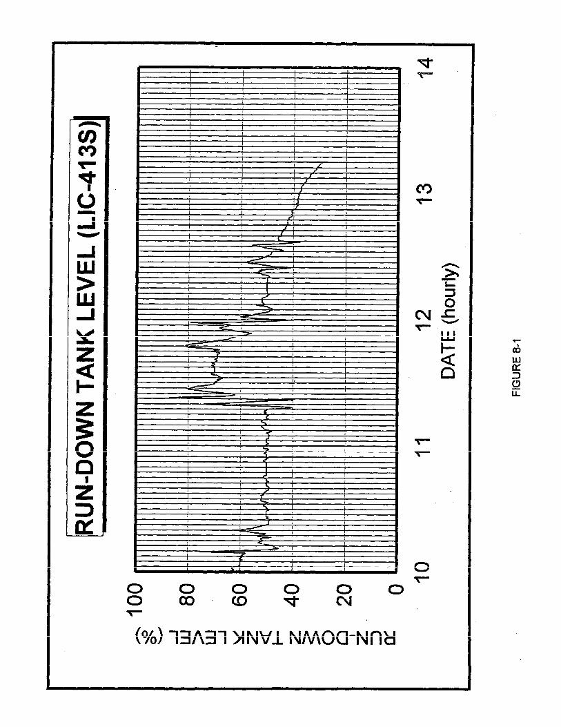
AN Plant Operations Page27
The rundown tank was equipped with a differential pressure sensor and controller (LIC-413) to measure and control the liquid level in the tank. Flow from the rundown tank was controlled by the associated level control valve (LCV-413), which was located on the discharge side of the AN 83% product pumps 404JA and 404JB. The product pumps were not equipped with low-flow or temperature sensors.
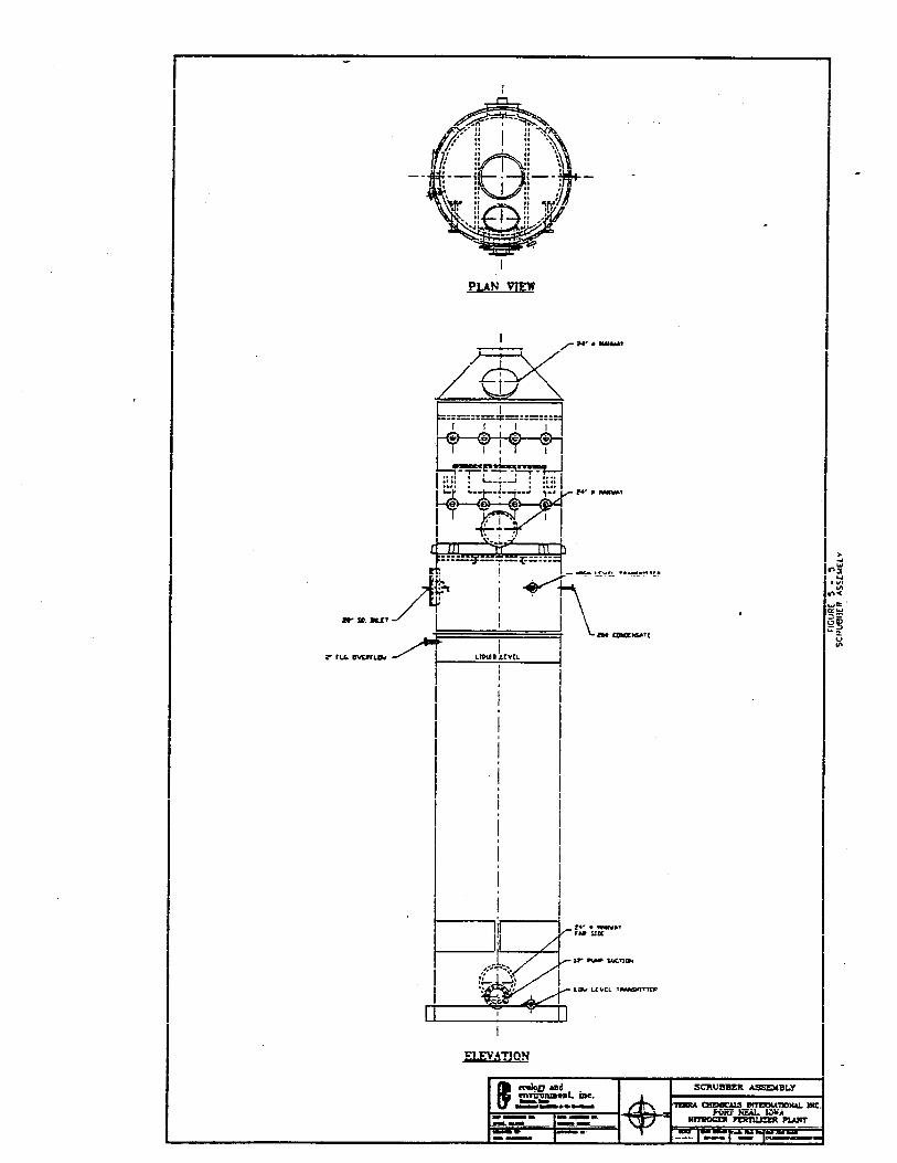
Ammonium Nitrate Scrubber
The AN scrubber was designed by BECO Engineering to remove ammonia vapors from the neutralizer and rundown tank process gases in the AN plant (Figure 5-5). Since use of a strong acid would have resulted in excessive acid aerosol production during scrubber operations, the scrubber was designed to operate with dilute nitric acid with a pH above 1.4 and a high recirculation rate, approximately 3,000 gallons per minute. The acidic liquor was circulated from the scrubber sump through spray nozzles located in the upper portion of the scrubber, where the free ammonia reacted with the stream to form a weak AN solution.
The scrubber was designed to operate efficiently with a 50% AN solution concentration. Tomaintain this concentration, the scrubber contents would be “blown down” (transferred) into the neutralizer. The estimated maximum design blowdown rate was 6.5 gallons per minute, with a normal constantly operating blowdown range designed to be between 2-3 gallons per minute (ID-Z).
Scrubber feedstreams included makeup eater consisting of 20-pound condensate and 55-56% nitric acid taken from the AN plant nitric acid line Approximately 90% of the nitric acid supply for the scrubber was taken from a point upstream of FCV-401 and injected on the suction side of the scrubber recirculation pump (416J) through a control valve The remaining 10% of the nitric acid supply was taken from a point downstream of FCV-401 and injected on the discharge side of 416J through the nitric acid metering pump (417J) The scrubber was designed to operate at a pH between 1.4 and 2.0, with optimal performance at a pH between 1.79 and 1.89. Operating at a pH less than 1.4 would cause excessive nitric acid emissions from the scrubber, and operating at a pH greater than 2.0 would cause an increase of ammonia emissions by reducing scrubber efficiency. BECO Engineering recommended setting the low pH alarm in the scrubber at 1.6.
The scrubber was equipped with a differential pressure sensor for level indication (ET-4 10). Condensate was controlled by a flow control valve (FCV-410). Scrubber solution pH was monitored by two pH probes located in the discharge line from the recirculation pump (AE-410 and AE-411). Nitric acid to the scrubber was controlled by a control valve (ACV-411) and the nitric acid metering pump (4173). Blowdown was controlled manually.
AN Plant Operations P a g e 2 9
Distributed Control System (DCS)
Since the Terra facility turnaround in September 1994, the AN plant had been operating with a Honeywell TDC 3000 Distributed Control System (DCS). As designed, Terra’s DCS was capable of monitoring and recording data, alerting operators to process variable deviation, and automatically operating the process (Figure 5-6).
There are three major control modes associated with TDC 3000 operation: manual, automatic, and cascade. In manual mode, the operator is in direct control of the output. In automatic mode, the DCS automatically adjusts the output to keep the process variable at its desired value (set point). In this mode, the operator controls the set point. In cascade mode, the output of one controller drives the set point of another controller which automatically adjusts the output to keep the variable at its desired value.
Any changes made to the process within each control mode are recorded in the DCS “Operator Process Change Journal.” This journal records all control mode changes as well as any set point changes (automatic mode) or output changes (manual mode) of any variable. All other process changes, i.e., the disabling and enabling of alarms and the change of alarm priorities, are also recorded in this journal.
The TDC 3000 is capable of alerting the operator when a variable reaches pre-programmed critically low or high values as designated by the programmer and/or engineer. These deviations are logged in the DCS “Process Alarm Journal.” Each alarm is assigned a priority depending on its importance, such as High, Low, and Journal. All process alarms are recorded in the DCS Process Alarm Journal, but only the first two categories alert the operator. An alarm assigned a Journal priority is recorded, but does not alert the operator. The alarm types, PVLL (process variable low/low), PVLO (process variable low) and PVHI (process variable high) are designated and pre-programmed into the DCS as the acceptable limits of operation. Any deviation outside of this range triggers an alarm whose priority depends on its pre-assigned importance.
For security reasons, the TDC 3000 has three distinct access levels (from low to high): operator, supervisor and engineer. The difference in access levels refers to the degree of authorization to make changes to the control system. The higher the level, the more additions, deletions, or changes can be made. The functions that fall within each access level were designated by the programmer/engineer when the system was designed. Under normal operations the DCS was to be set in operator access level. Within this level, the operator is able to change modes of operation and change set points and outputs. Engineering access level allows alteration of the system’s algorithm and alarm priority.
AN Plant Operations Page31
SECTION 6: FACILITY EVENTS
The investigation team developed a time line of activities and events that occurred at the Terra Port Neal facility prior to the explosion. The time line was developed to provide an overview of these events and any possible connection to the explosion.
On November 27, 1994, operations and maintenance personnel determined that the pH probe located in the neutralizer rundown line was defective. There were no spare probes in stock, so the AN plant was operated with the apparently defective probe in service until the time of the explosion.
Shift reports requested by the investigation team and provided by Terra indicated that the surface condenser in the nitric acid plant was recorded as leaking from December 5 (1st shift report requested by the investigation team) through December 8, 1994. Repairs to the surface condenser were performed on December 8. The acid plant was shut down two more times prior to the explosion, the last being an emergency shutdown that occurred at approximately 0430 hours on December 12.
At approximately 2200 hours on December 11, the outside operator in the AN plant detected an acid condition in the neutralizer. The pH of a grab sample analyzed by the outside operator indicated the neutralizer pH was -1.5. Information provided in depositions indicated that nitric acid fumes were strong enough in the AN plant to bum the outside operator’s face [ID-3). An off-duty operator was called in to collect samples from the neutralizer to monitor pH and concentration of the AN solution until the neutralizer was operating within the acceptable pH and concentration range. The operator collected a sample about every 10 minutes and used a portable pH probe to determine pH and a hydrometer to determine concentration The neutralizer was within operating parameters by approximately 0100 hours on December 12. Grab sample results for this period of time were not logged.
At approximately 0200 hours on December 12, the outside AN plant operator observed a leak in the condensate line leading to the AN scrubber. He observed that the condensate line was leaking where it connected to the scrubber. As he attempted to get a closer look, the operator stated that he was sprayed with hot ammonium nitrate solution coming from a leak in a discharge gasket on the north AN product pump. The operator shut down the north pump and started the south product pump, which also leaked. The operator and shift supervisor changed the discharge gasket on the north pump and returned it to service. The operator could give no estimate of the amount of
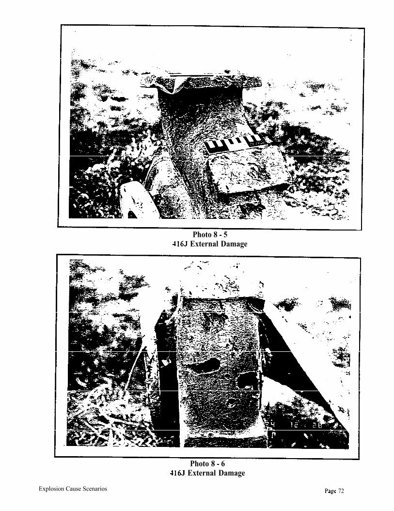
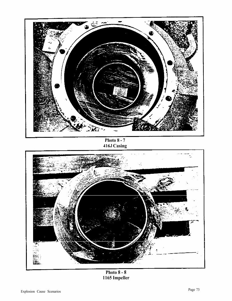
ammonium nitrate released from the leaking pump. At approximately 0240 hours, the outside operator and shift supervisor shut down the AN scrubber recirculation pump (416J) and blocked in the leaking condensate line. The condensate line remained blocked in until the explosion. [ID-l ,ID-3]
The nitric acid supply began running low on the afternoon of December 12 because the nitric acid plant was still out of service. Operators began shutting down the AN plant at approximately 1410 hours by reducing the nitric acid flow to the neutralizer. The neutralizer was shut down by 1500 hours.
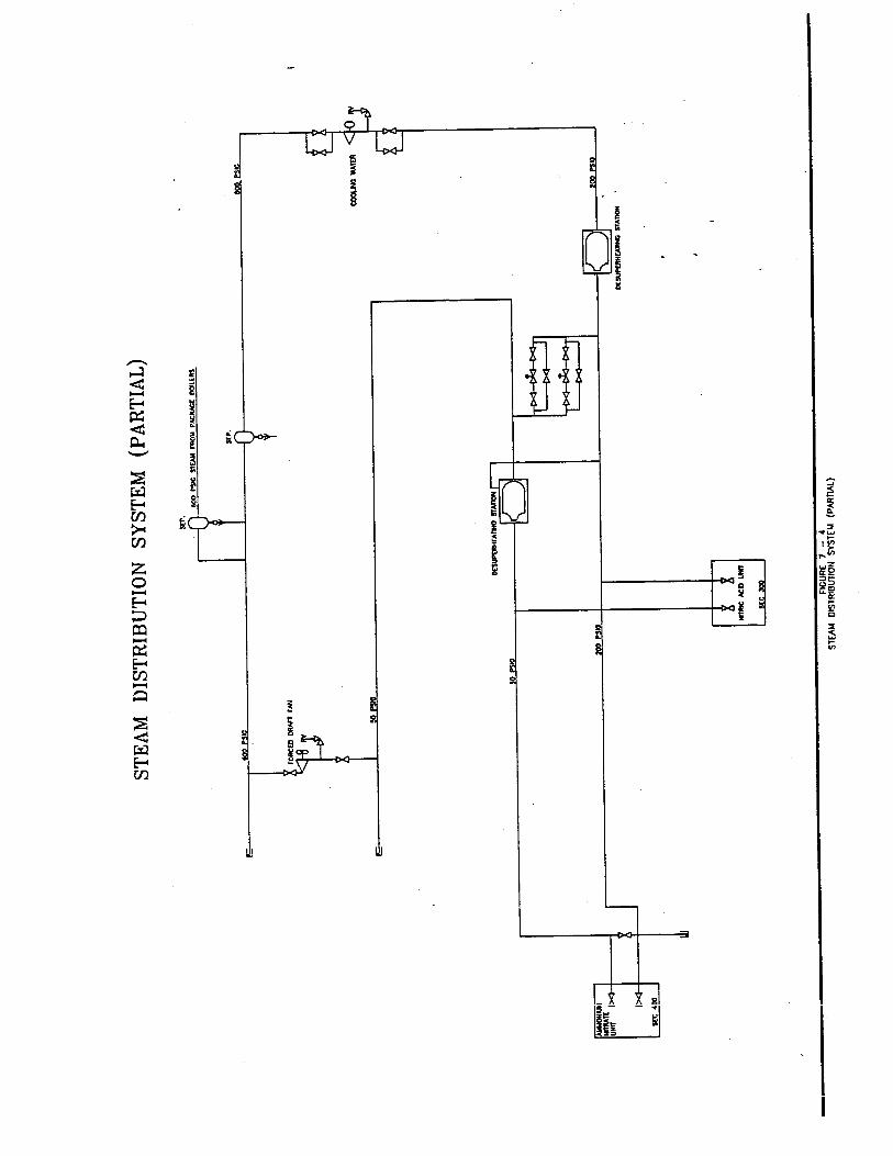
Terra Facility Events Page33
AN product pumps were shut down and blocked in at approximately 1452 hours by the outside operator. The operator applied 200 psig steam to the AN product line on the suction side of the product pumps. The steam remained applied until the time of the explosion.
At approximately 1500 hours, operators applied compressed air to the suction side of the nitric acid pump located in the nitric acid plant. The “plant air” was applied to the nitric acid line to purge the line of nitric acid to prevent freezing. The nitric acid was discharged from the line into the AN neutralizer. The air was applied until approximately 2030 hours. Terra employees stated that plant air applied to the neutralizer resulted in strong acid gases in the AN plant [ID-3]. This required them to wait a short period of time after shutting down the plant air before steam could be applied to the spargers to allow the acid fumes to disperse.
At approximately 2030 hours, the operator applied 200 psig steam to the nitric acid line at a point downstream from FCV-401 at a 3/4-inch diameter fitting. The operator stated that a l-inch diameter flexible steam line was connected at that location and that the steam valve was fully opened [ID-3]. The steam was applied to prevent the backflow of AN into the nitric acid spargers in the neutralizer and to prevent the AN from salting up the holes in the sparger.
At approximately 1650 hours, operators started the AN scrubber recirculation pump and started blowdown of scrubber contents into the neutralizer. Blowdown continued until approximately 1805 hours, then was discontinued. The AN scrubber pump continued to run until the explosion. There were no nitric acid or condensate feeds to the scrubber during this time.
Based on information provided in depositions, the outside operator conducted an inspection of the AN plant at approximately 2100 hours on December 12, and a final waIk-through at 0530 hours on December 13.
By 0600 hours, December 13, the nitric acid plant air compressor was in “slow roll” in preparation for startup. At least two explosions occurred in the AN plant at approximately 0606 hours on December 13.
Terra Facility Events Page 34
SECTION 7: INVESTIGATION-DERIVED FACTS AND CONDITIONS..
Acidity
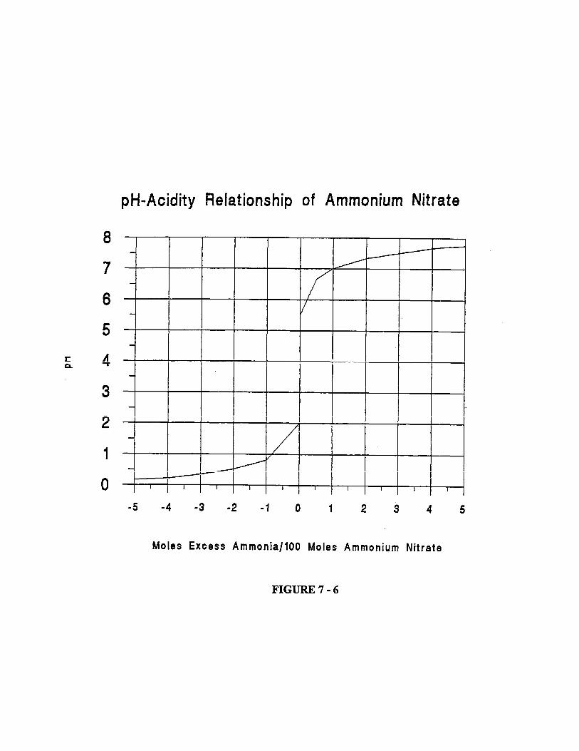
Information reviewed by the investigation team indicates that the degradation of ammonium nitrate is an autocatalytic liquid-phase reaction, the rate of which is proportional to the product of the mass of the AN salt and the concentration of acid. The activation energy for this process was determined experimentally to be 31.4 kcal/mol at a temperature of approximately 338°F. Results of studies indicate that the thermal degradation of ammonium nitrate takes place in the liquid phase and is autocatalyzed by acid. Experiments have determined that the mass rate of decomposition of AN is a function of the mass of acid present in the melt and is not affected by such products of reaction as water vapor and nitrous oxide. The addition of ammonia almost completely inhibits this reaction by reacting with the excess acid to form ammonium nitrate. Since the solubility of ammonia in liquid ammonium nitrate is much less than that of the acid, the inhibition will not occur until a sufficiently high concentration of ammonia has accumulated in the vapor phase. The thermal decomposition of ammonium nitrate involves the evolution of ammonia, but the low solubility in ammonium nitrate and an atmospherically vented vessel would not allow sufficient ammonia to accumulate in the vapor phase to inhibit the reaction [2,18]
Review of additional materials and interviews with operators and engineers at other facilities that produce ammonium nitrate revealed that neutralizers are routinely operated at a pH as low as 2.4. The resultant AN is “polished” in rundown vessels by sparging anhydrous ammonia into the solution prior to storage or further production processes. All information gathered by the investigation team indicated that AN solutions should not be stored or processed further until the pH had been raised to approximately 6 or higher. Ammonium nitrate scrubbers that operate in low pH ranges are so designed because the product will not be stored at that pH for prolonged periods of time.
Prior to shutting down the AN neutralizer, Terra personnel detected an acid condition in the neutralizer. Offgas from the urea plant was used to raise the pH in the neutralizer after the nitric acid flow had been shut down. Plant air was then used to clear the nitric acid line (3-inch diameter) of nitric acid by blowing it into the neutralizer through the acid spargers. The acid plant was located approximately 600 feet from the neutralizer. Calculations determined that the line volume of the nitric acid line was approximately 220 gallons, and when mixed with the static neutralizer contents would have resulted in a pH of approximately 0.8 (calculation).
Analytical data provided by Terra indicates that the pH of the AN solution in the west storage tank at the time of the explosion was approximately 1.4 at standard temperature. The investigation team concluded that the pH of the rundown tank contents was less than 1.4.
Written operating procedures at AN facilities visited. by the investigation team require that the pH of all process vessels be adjusted to approximately 6.0 when the plant is shut down. pH is adjusted utilizing ammonia spargers in each vessel. If the vessels remain charged during the shutdown period, pH is monitored as it would normally be with the process operating. Procedures at these
Investigation-Derived Facts and Conditions P a g e 3 5
facilities indicate that low pH in AN solutions when the process is down is to be avoided.
The investigation team determined that the low pH in the neutralizer and rundown tank was a factor contributing to the explosion.
Contaminants
Chlorides
The presence of chlorides reduces the activation energy necessary to initiate thermal decomposition of ammonium nitrate. Chlorides also react synergistically with some metals to further sensitize ammonium nitrate [3, 4, 5, 6 ,14].
Potential chloride sources identified at the Terra facility were the nitric acid plant and facility cooling water. Information obtained from employee interviews and depositions, operator logs, and maintenance records indicates that there was at least one serious leak in the nitric acid plant surface condenser that could have allowed facility cooling water to contaminate the condensate. This leak was recorded on operator logs from December 5-8, and led to a nitric acid plant shutdown on December 8. The investigation team did not request logs prior to December 5, and was unable to determine how long the surface condenser had been leaking prior to December 5. Condensate is used as makeup water for the nitric acid absorption column and the AN scrubber. Two nitric acid cooling condensers were also indicated as leaking, possibly allowing facility cooling water to enter the nitric acid process gas stream. Increased chloride concentrations are also likely during unstable acid plant operations, such as during startup and shutdown, and the nitric acid plant had been started twice and shut down three times during the week preceding the explosion. Chlorides formed during acid plant operations concentrate in the weak acid trays of the absorption column. Following the emergency shutdown of the nitric acid plant on December 12, contents of the absorption column were pumped to the nitric acid storage tank, introducing chlorides into the AN plant feed stream.
The investigation team concluded that chlorides were present in the nitric acid used in the AN plant. Analytical data provided by Terra indicated chloride concentrations in the west AN storage tank were 168 parts per million, and 557 parts per million in the nitric acid absorption column.
The investigation team concluded that chlorides were present in the neutralizer, rundown tank, and west AN storage tank at the time of the explosion. The investigation team determined that chlorides were a factor in the explosion.
Petroleum
Hydrocarbons, as a reducing agent, increase the sensitivity of AN to detonation initiation.
Information obtained through Terra employee interviews and documents provided by Terra indicated that two significant oil releases had occurred in the ammonia plant around October 1994 [ID-4, ID-15, ID-21].
Investigation-Derived Facts and Conditions Page 36
The first incident occurred during startup after the September turnaround while ammonia plant compressor 103J (syngas compressor) was in slow roll. A back-pressure regulator failed and allowed oil to be discharged into areas other than the process stream. Plant operators indicated that at the time of the incident, there was no process gas in the synthesis loop. Terra personnel indicated that several barrels of oil were recovered and that hot boiler feed water had been used to flush the system after oil recovery.
The second incident occurred sometime in October. Ammonia plant compressor 105J released oil into the refrigeration system. Operators stated that there was some communication with the process stream, but oil typically would settle in heat exchangers. Although a small amount might end up in storage, most would be recovered from the exchangers. Approximately 35 barrels of oil was recovered from this incident.
Hydrocarbon analysis submitted by Terra indicated that trace levels of hydrocarbons were present in the acid plant feed stream to the AN plant. Terra submitted laboratory analyses that indicated the presence of 2.6% TOC in the offgas line from the urea plant to the AN neutralizer. Thisline had been severely damaged by the explosion. No significant hydrocarbon presence was indicated in the AN storage tanks in other analytical data provided by Terra.
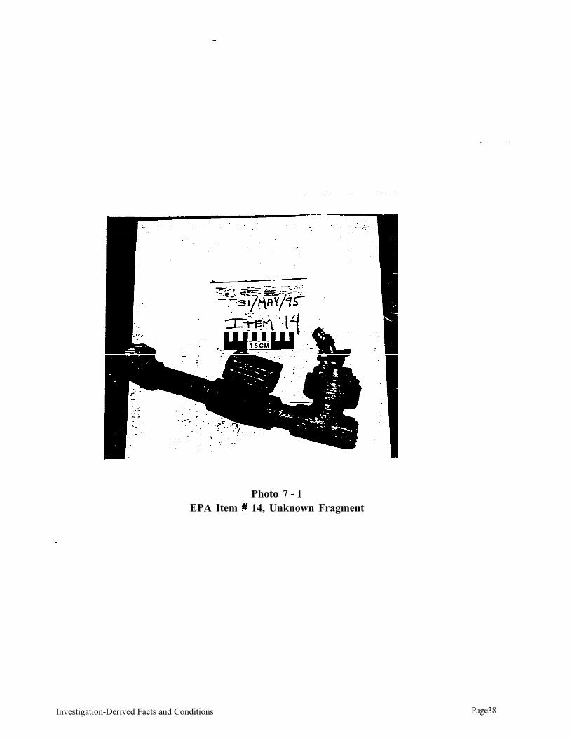
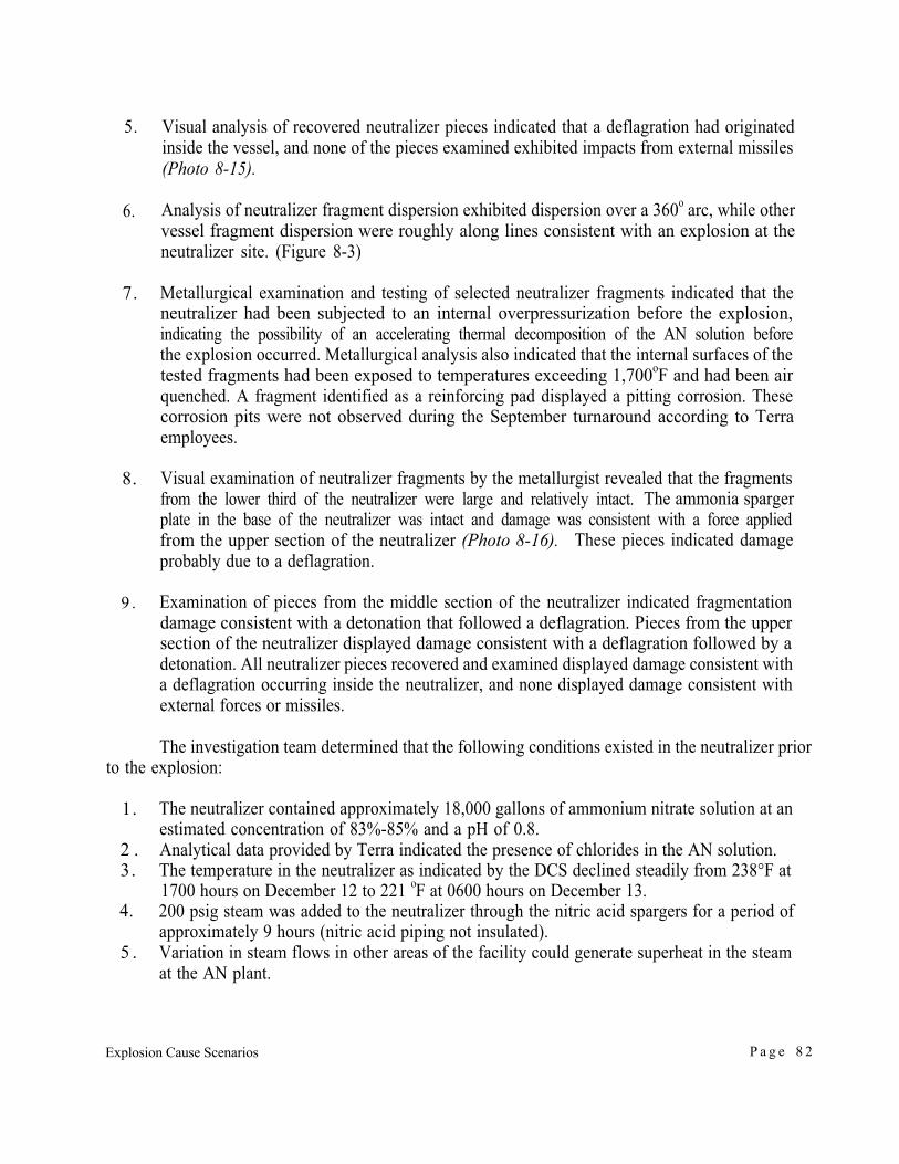
EPA’s metallurgical analysis of a stainless steel pipe fragment with a closed block valve on one end and a check valve on the other end (EPA Item #14) revealed that the residue in the pipe contained a concentration of 8% total petroleum hydrocarbon (Photo 7-1). Terra employees tentatively identified the pipe section as part of a chemical stripper located near the AN plant. Theinvestigation team requested a piping diagram and a drawing of the chemical stripper to determine whether or not the petroleum hydrocarbons detected in the pipe fragment could have contributed to the explosion. The location of this fragment prior to the explosion could not be accurate ascertained.
Terra had experienced problems with the plant air compressor oil filters during and following the September 1994 turnaround. The investigation team could not locate piping associated with the plant air system for analysis for petroleum hydrocarbons. Plant air was applied to the neutralizer nitric acid spargers for over five hours after the AN plant was shut down on September 12.
The rundown tank design would possibly have allowed the rundown tank to function as an oil separator, minimizing oil transfer to the storage tanks.
Based on information available to the investigation team when the report was completed, hydrocarbon contamination could not be eliminated as a factor in the explosion.
Investigation-Derived Facts and Conditions Page 37
Photo 7 1 EPA Item 14, Unknown Fragment
Investigation-Derived Facts and Conditions Page38
Low Density Areas
Bubbles in the AN solution create low density areas. It has been shown that air, steam, and offgas bubbles will provide “hot spots” during thermal decomposition or deflagration because the gas they contain is adiabatically compressed by the advancing pressure wave front [ 1, 23, 24, 30]. These hot spots assist propagation of the detonation.The increase in internal surface area is of considerable importance with respect to the sensitization of ammonium nitrate-based explosives. Lowering the density of the AN solution also reduces the thermal inertia of the system which, along with the lack of flow in the neutralizer, increased the probability of creating local heating problems.
Compressed air, then 200 psig steam, had been applied to the nitric acid spargers in the neutralizer from approximately 1500 hours on December 12 until the time of the explosion. Compressed air entering the neutralizer through the nitric acid spargers created bubbles in the AN solution. Steam entering the neutralizer through the spargers would also create bubbles in the AN solution, and continued steam injection could create a low-density zone in the area immediately outside of the nitric acid sparger.
The investigation team concluded that the creation of local, low-density zones was a factor in the explosion.
Temperature
The probability of thermal decomposition occurring in AN solutions is proportional to temperature. The activation energy required to inmate thermal decomposition decreases with the presence of contaminants in the AN solution [21, 34] Potential energy sources present in the AN plant after shutdown and before the explosion were limited to the AN scrubber recirculation pump, AN product pumps, and the 200 psig steam applied to the nitric acid spargers in the neutralizer.
The investigation team concluded that the addition of energy to the AN solution via the 200 psig steam was a significant factor in the explosion.
Confinement
Confinement is necessary for AN to deflagrate or detonate [21]. The degree of confinement needed for to support deflagration decreases as the presence of contaminants increases. Confinementcan result from physical containment (containers) or from the mass of the AN. The mass of the liquid ammonium nitrate may be sufficient confinement to support the deflagration or detonation of the AN in the presence of contaminants and low density areas.
The investigation team concluded that the mass of the AN solution was sufficient confinement to initiate deflagration, that overwhelmed the venting capacity of the vessels due to the presence of contaminants, low pH, and a high-temperature local heat source.
Investigation-Derived Facts and Conditions P a g e 3 9
Concentration
Operator shift reports and logs indicate that AN solution concentration varied from 82% through 85% during normal operations. Lower concentrations occurred when the neutralizer was operated at a pH of 2 or less, and higher concentrations occurred when the neutralizer was operated at a pH greater than 6.
The investigation team concluded that the concentration of the AN in the neutralizer and rundown tank at the time of the explosion was within this range.
Materials of Construction
Process vessels and piping in the AN plant were constructed of 304L stainless steel. 304Lstainless steel is an alloy containing the following metals in approximate concentration by weight: chromium 19%, nickel 9%, carbon no more than 0.08%, with the balance iron. Both chromium and nickel ions are listed as metals that have a synergistic effect with chlorides in the catalysis of the thermal decomposition of ammonium nitrate [3, 8, 9, 14 ]. One stainless steel piece of the neutralizer that showed signs of severe corrosion was submitted for metallurgical analysis to determine if the corrosion, and subsequent release of alloy metals, occurred as a result of the explosion or may have contributed to the explosion.
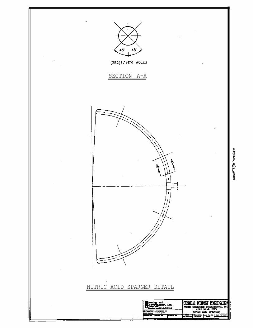
The only process vessel components not constructed from 304L stainless steel were the AN neutralizer nitric acid Schedule 40 titanium spargers. Each sparger was 3-inch diameter with a radius of curvature of 4 feet and contained 252- l/16-inch diameter holes (Figure 7-1).
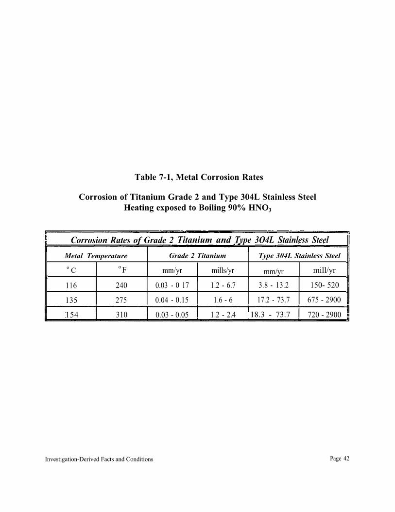
Information gathered by the investigation team indicate that titanium has been used for handling and producing nitric acid in applications in which stainless steels have experienced significantuniform or intergranular attack. A comparison of the corrosion rates for grade 2 titanium and 304L stainless steel in boiling 90% nitric acid is contained in Table 7-1. The presence of some impurities in the nitric acid, including the presence of titanium ions, inhibits the corrosion of titanium in nitric acid [41].
The neutralizer and the nitric acid spargers were inspected during the September, 1994 facility turnaround. Interviews and depositions of Terra employees vary in reference to the description of the neutralizer and spargers, but all agree that the neutralizer and the nitric acid spargers visibly appeared to be in good condition when inspected during turnaround.
Investigation-Derived Facts and Conditions Page40
SECTION A-A
NITRIC ACID SPARGER DETAIL
Table 7-1, Metal Corrosion Rates
Corrosion of Titanium Grade 2 and Type 304L Stainless Steel Heating exposed to Boiling 90% HNO3
Corrosion Rates of Grade 2 Titanium and Type 3O4L Stainless Steel Metal Temperature Grade 2 Titanium Type 304L Stainless Steel o C o F mm/yr mills/yr mm/yr mill/yr
Investigation-Derived Facts and Conditions Page 42
The investigation team requested written procedures or guidance documents for the visual inspection of this vessel to include guidance for conditions that would trigger futher inspection and testing. Terra employees stated that there were no written guidelines or procedures for vessel inspections or conditions that would warrant closer inspection-or testing of the vessel [ID-21]. Theinvestigation team requested a copy of the inspection report that had been completed during the September turnaround, and had not received the document by the time this report was issued.
The investigation team examined fragments from Terra AN plant equipment that had been assembled by Baker Engineering personnel in a warehouse located north of the Terra facility. Themetallurgist retained by EPA examined fragments identified as originating from the AN neutralizer, rundown tank, scrubber, and associated piping and appurtenances for further metallurgical examination and testing. Items selected included:
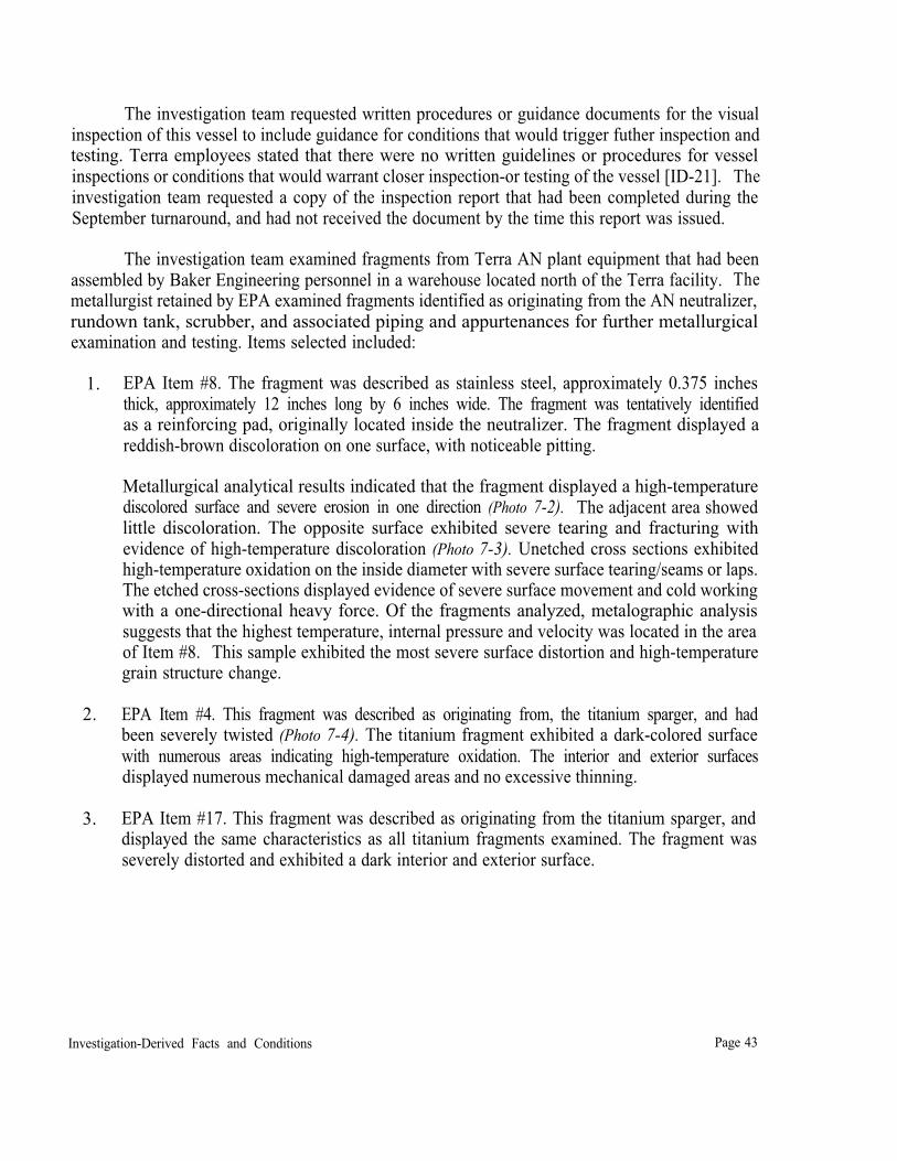
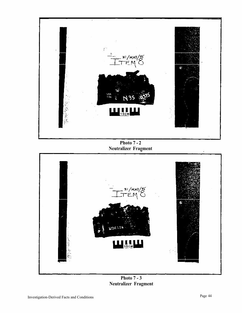
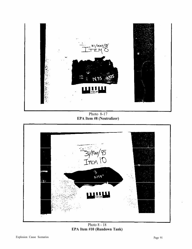
1. EPA Item #8. The fragment was described as stainless steel, approximately 0.375 inches thick, approximately 12 inches long by 6 inches wide. The fragment was tentatively identified as a reinforcing pad, originally located inside the neutralizer. The fragment displayed a reddish-brown discoloration on one surface, with noticeable pitting.
Metallurgical analytical results indicated that the fragment displayed a high-temperature discolored surface and severe erosion in one direction (Photo 7-2). The adjacent area showed little discoloration. The opposite surface exhibited severe tearing and fracturing with evidence of high-temperature discoloration (Photo 7-3). Unetched cross sections exhibited high-temperature oxidation on the inside diameter with severe surface tearing/seams or laps. The etched cross-sections displayed evidence of severe surface movement and cold working with a one-directional heavy force. Of the fragments analyzed, metalographic analysis suggests that the highest temperature, internal pressure and velocity was located in the area of Item #8. This sample exhibited the most severe surface distortion and high-temperature grain structure change.
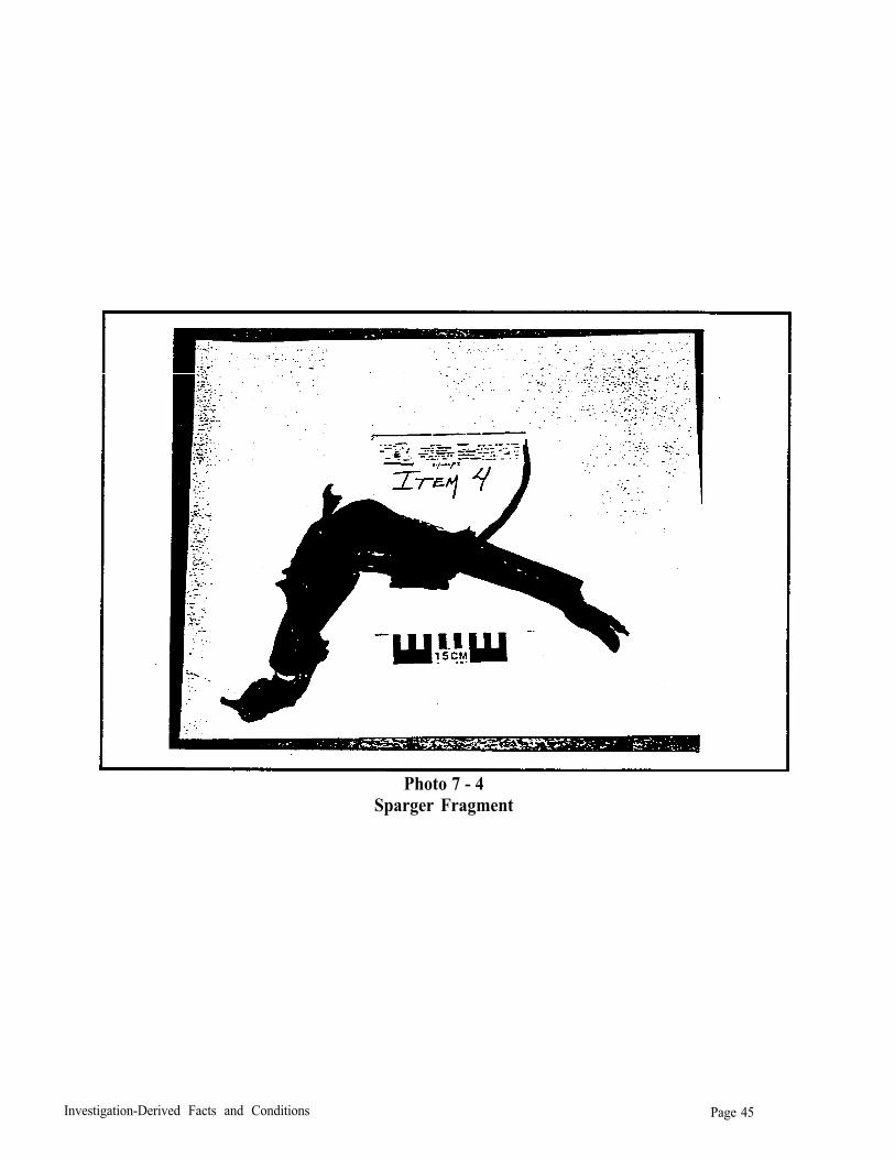
2. EPA Item #4. This fragment was described as originating from, the titanium sparger, and had been severely twisted (Photo 7-4). The titanium fragment exhibited a dark-colored surface with numerous areas indicating high-temperature oxidation. The interior and exterior surfaces displayed numerous mechanical damaged areas and no excessive thinning.
3. EPA Item #17. This fragment was described as originating from the titanium sparger, and displayed the same characteristics as all titanium fragments examined. The fragment was severely distorted and exhibited a dark interior and exterior surface.
Investigation-Derived Facts and Conditions Page 43
Photo 7 Neutralizer Fragment
Photo 7 - 3 Neutralizer Fragment
Investigation-Derived Facts and Conditions Page 44
Photo 7 - 4 Sparger Fragment
Investigation-Derived Facts and Conditions Page 45
The unetched cross-sections of the outside diameter surface displayed surface indications of heat cracking and deterioration. The etched cross-sections revealed that the parent material had a grain structure typical of titanium which had been heat treated and quenched from 1,300oF. The external surface exhibited a structure similar to one that had been exposed to a 1,700oF temperature and then quenched. The inside surface displayed a slightly lower temperature range with slight surface change.
Titanium sparger fragmentsexamined exhibited an oxide coating on the interior surfaces, and some pitting on the exterior surfaces. General metallurgical results indicate that some of the fragments were exposed to a temperature equal to or greater than 1,700oF inside the neutralizer. Titanium fragments examined indicated that the highest temperatures impinged on the outer surfaces. These high temperatures appeared to be a local event inside of the neutralizer, and not an event that occurred uniformly throughout the neutralizer. The high-temperature area was proximate to the nitric acid spargers.
The investigation team determined that metallurgical observations and analyses indicated that a local area inside the neutralizer had been exposed to a temperature equal to or exceeding 1,700oF.The highest temperatures appear to have been proximal to the nitric acid spargers. Analysis of neutralizer and rundown tank fragments indicate that the vessels had been overpressured prior to fragmenting, indicating that all or a portion of the vessel contents had deflagrated.
Analyses confirmed that both the neutralizer and rundown tank exploded.
Rundown pH Probe
The pH probe used by Terra to monitor pH in the neutralizer rundown line in the AN plant was changed from a monitoring system requiring sample dilution and cooling to a monitoring systemthat inserted the pH probe directly into the process stream. The new probe was designed to operate up to a maximum temperature of 140°C (284°F).
The investigation revealed that the rundown sample line had been replaced when the pH probe was changed, that the old pH cell had been removed and the new probe directly inserted in the rundown pH line. The rundown pH sample line originated from the rundown line and terminated in the rundown tank. The line was stainless steel, 3/4-inch diameter from the rundown line to the pH cell, and 1/2-inch diameter from the pH cell to the rundown tank. The AN P&ID showing this change indicated that the pH sample line was not insulated or steam traced. This fact was confirmed through a written communication by Terra. The investigation team requested drawings and specifications for the pH sample line. The investigation team concluded that the design of the pH sample line could have contributed to the problems attributed to the pH probe.
Operations and maintenance personnel stated that the pH probe in the AN neutralizer rundown line was not functioning properly on November 27, 1994. Work Order # EM001076 indicates that there were no more pH probes in stock, and that the replacement pH probe was due on December 21, 1994. Interviews with Terra employees indicated that a probe of the new type was
Investigation-Derived Facts and Conditions Page 46
expected to have a service life of approximately 30 days, and that two spare probes. were to be maintained in inventory [ID-14, ID-23]. No spare probes were available, so the AN unit operated from November 27, 1994 until the time of the explosion without a dependable pH feedback control loop on the DCS.
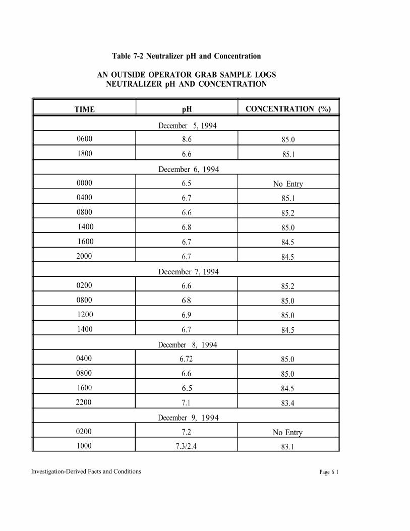
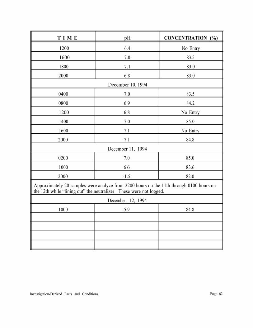
Operators and engineering personnel stated that if pH probe readings were not reliable, grab samples of AN from the neutralizer or rundown line would be manually analyzed by the outside operator at least every two hours to determine concentration and pH [ID-l, ID-9, ID-19, ID-23] Table 7-2, included at the end of this section, summarizes all documented grab sample analyses from December 5 -December 13, 1994. Documentation provided by Terra indicates that if grab samples were collected every two hours from December 5 through the time of the explosion, that the sample results were not logged.
Information obtained from interviews and depositions indicated that operators detected a strong acid condition in the AN neutralizer at 2000 hours on December 11, with pH indications in negative numbers by the portable pH probe, as well as by acid fumes burning an operator’s face in the AN plant. An off duty operator was called to the plant to assist the board operator in “lining out the neutralizer” (adjusting pH to within normal operating ranges). This activity requires the operator who was called in to work to collect samples from the neutralizer and relay pH readings to the board operator, who would adjust the acid flow into the neutralizer. Approximately 20 samples were collected and analyzed by the outside operator from 2200 hours until 0100 hours. No logged grab samples were analyzed between 1000 hours and 2000 hours on December 11.
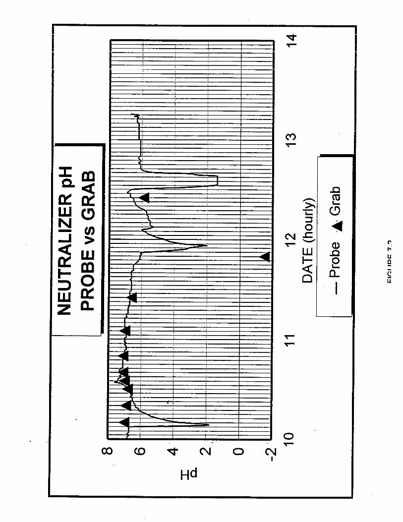
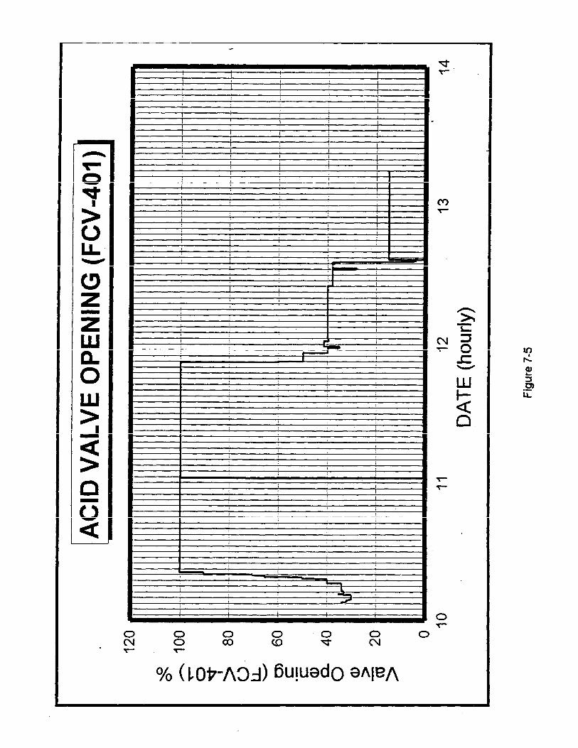
The investigation team requested all AN plant DCS data from December 5, 1994, through the time of the explosion. Terra provided DCS data for the AN plant for December 10 through the time of the explosion, with over 24 hours of data missing from 0950 hours on December 11 through 1100 hours on December 12. Terra employees stated that the missing DCS data contained only steady state operational data, therefore the data was not recovered from the DCS digital history [ID-14]. EPA investigators determined from operator logs and interviews that the neutralizer had become acidic enough during this time (pH -1.5 on log sheet) that an extra outside operator was called to work to take grab samples to return the neutralizer to a normal pH operating range. EPA obtained the missing data directly from Honeywell with Terra’s permission.
The investigation team graphed the DCS data and observed that the pH probe appeared to be operational. Comparison to the limited operator grab sample analyses conducted confirmed that the pH probe was tracking pH trends in the rundown line and accurately reflected reported acidic excursions in the AN neutralizer (Figure 7-2). Mass balances and pH calculations conducted utilizing DCS data for offgas flow and nitric acid flows accurately followed the indicated, pH curve for the neutralizer rundown line: The pH probe readings lagged-behind pH changes; with the lag time varying from two to three hours. The investigation team provided graphs generated from DCS data provided by Terra to Terra engineers and operators to review. All agreed that the pH probe appeared to be working, but could not state whether or not the indications were accurate [ID-4, ID-18, ID-21, ID-23]. They did state that the probe appeared to be accurately indicating pH trends in the neutralizer.
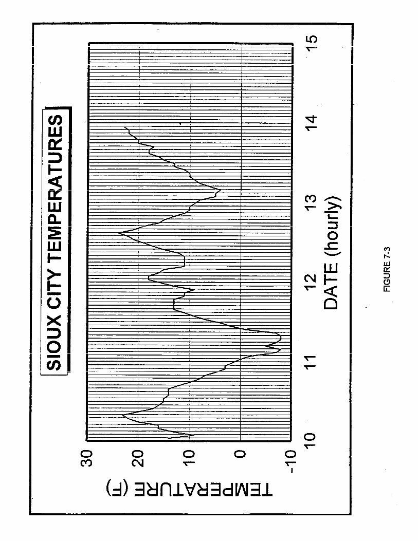
Investigation-Derived Facts and Conditions Page 47
The investigation team contacted persons familiar with pH probe operations, who advised that the pH probe did appear to be working and indicated that response delays might be caused by an intermittent obstruction in the rundown sample line. The physical configuration of the sample line could contribute to this problem, as well as ambient temperatures. Ambient temperatures for the Sioux City, Iowa, area are contained in Figure 7-3.
The investigation team determined that the problems associated with the rundown pH probe and sample line contributed to pH problems during normal operations, but that it was not a factor in the explosion of the neutralizer. The investigation team determined that the problems with the pH probe contributed to the low pH in the rundown tank and the low pH detected in the west AN storage tank.
Steam Distribution System
The steam system at the Terra Port Neal facility was a multi-level system designed with the apparent intent of supplying steam for a diverse range of purposes in an energy efficient manner (Figure 7-4). Steam was produced in packaged boilers at a nominal pressure of 600 psig. The investigation team assumed that the boilers were equipped with superheaters to ensure a supply of dry steam for turbine drivers operating directly off the 600 psig header.
Steam from the boilers was utilized for a variety of functions within the facility beginning with the steam turbine drivers and including a wide range of process, tank and space heating uses. Most applications, other than the turbine drivers, utilized 200 psig or 50 psig steam. These two lower pressure levels were supplied by varying combinations of turbine exhaust steam and steam depressured directly from the 600 psig header Since the steam requirements for the different process and heating loads would have varied, both with operations and ambient temperature, and since some of the processes were also steam producers, the load on the boilers and the relative amounts of depressured and exhaust steam in each header probably varied over a wide range.
Desuperheating stations were provided to remove the excess superheat from the depressurized steam. Presumably, these stations were originally designed for the range of depressuring loads that could be foreseen for startup, shutdow and the full range of normal operating conditions. Whether or not they were still capable of covering the full range of loads after numerous modifications to the plant is not known. It is conceivable, however, that the desuperheater at the 600 psig to 200 psig depressuring station could have been temporarily overtaxed by high loads, such as might have resulted from startup, upset, or non-standard operations. In that event, there would have been a carry-over of excessive superheat downstream of the superheater.
The investigation team concluded that the steam distribution system had the potential to supply superheat during high demand events such as the slow roll of the nitric acid compressor.
Investigation-Derived Facts and Conditions Page 48
Air and Steam in Spargers
At approximately 1500 hours December 12, Terra personnel blocked in the acid line from the nitric acid plant and began to blow out the line from the acid plant to the neutralizer with plant air. This operation was not included in the standard operating procedures provided by Terra. Informationobtained during interviews indicates that the purpose of this procedure was to clear the nitric acid lines of acid from the acid plant to the neutralizer spargers to prevent the acid from freezing [ID-4]. Operators also applied 200 psig steam to the AN line from the 83% process pumps to the storage tanks located in the tank farm.
Information obtained from depositions and interviews indicates that the normally practiced procedure was to quickly clear the lines of nitric acid, then remove the air and block in the lines. Plant air was injected in the nitric acid line and discharged through the neutralizer nitric acid sparger until approximately 2030 hours. Plant air is approximately 110 psig and is approximately ambient air temperature. The ambient air temperature for this time period ranged from approximately 24°F dropping to 13°F during this time. Air was discharged into the AN solution in the neutralizer creating low density zones in the solution. Information obtained both from references and operating procedures from other facilities indicate that creation of low density zones in ammonium nitrate solutions is a practice that is to be avoided.
At approximately 2030 hours on December 12, the outside operator disconnected the plant air from the nitric acid line leading to the AN plant and blocked in this line. The outside operator applied 200 psig steam through a fitting downstream from FCV-401. Fittings to connect the steam line were stated to be 3/4-inch in diameter, the steam hose diameter was one inch, and the steam valve was completely opened.
Terra employees stated that the addition of steam was a normal procedure to prevent backflow into the neutralizer nitric acid spargers and to keep the spargers from salting out. Interviews of personnel ranging from operators to supervisors and managers indicated that there was no specific procedure for connecting steam to the spargers [ID-4]. Two steam supplies were available in the AN unit, 50 psig and 200 psig As explained to the investigation team, each operator performed this task differently, but should only open the steam valve until flow was established. No preference was given to either of the two steam supplies. The temperature of 200 psig saturated steam is 387oF, and the temperature of 50 psig saturated steam is 297o F. The investigation team determined that since the nitric acid plant was in “slow roll” at the time of the explosion, it was possible that there was superheat in the steam applied to the neutralizer prior to the explosion that was not present before the nitric acid plant startup. This could have resulted in steam temperatures exceeding 400°F being available in the 200 psig supply.
Drawings provided to Terra for the construction of the neutralizer by Mississippi Chemical show block or check valves attached to the nitric acid spargers where they exit the vessel. The neutralizer at Terra was not equipped with check or block valves at these locations, but was equipped with a barometric loop that allowed backflow into the spargers and into the nitric acid line back to the barometric loop. The nitric acid line was not insulated or steam traced. Terra could not produce
Investigation-Derived Facts and Conditions Page 52
any design or “as built” engineering drawings for the Mississippi Chemical neutralizer that Terra contracted to have constructed.
The investigation team interviewed engineers and operators at other ammonium nitrate facilities in reference to the use of steam in AN vessels and lines. One facility did not use any steam in the neutralizer or other AN process vessels other than in steam coils. When the AN plant was shut down at one of the facilities, the neutralizer was drained and flushed with water. Other facilities used no more than 90-pound steam in any AN vessel and line, and then only under direct supervision. Thetemperature of 90-pound saturated steam is 331°F.This steam is applied through ammonia spargers with minimal flow to avoid creating low density zones. No one interviewed recommended the use of steam in AN applications where any degree of confinement could be generated. Mississippi Chemical neutralizer designs viewed by the investigation team during tours of these facilities were all equipped with check or block valves where the nitric acid lines connect to the spargers to prevent backflow.
The investigation team determined that the use of 200 psig steam applied through a completely open steam valve to the neutralizer nitric acid spargers was a factor in the explosion.
Nitric Acid Supply
The investigation team graphed AN plant DCS data provided by Terra to document conditions in the AN plant for three days preceding the explosion. DCS data indicated that from 0903 hours on December 10 through 2050 hours on December 11, the neutralizer nitric acid control valve (FCV-401) was 100% open (Figure7-5). Outside operator grab sample analyses for these periods indicate a rundown pH in the 7.0 range, heavily on the free ammonia side of the AN pH curve (Figure 7-6). Urea offgas flow during this period ranged from 70-85%. It appeared to the investigation team that when the urea plants were operating efficiently, the supply of nitric acid to the AN plant was limited and would not maintain the specified pH range of 5.5-6.5.
Interviews with Terra employees indicated that acid supply to the AN plant had been a periodic problem for a few years prior to the installation of the scrubber [ID-14, ID-23]. Terraincreased the nitric acid pump capacity to overcome the problem, but periodic shortages still occurred in the AN plant, apparently due to losses in the piping resulting from a combination of pipe diameter and length. The investigation team determined that when the AN scrubber was installed, the nitric acid supply for the scrubber was taken from the same nitric acid line that supplied the neutralizer without increasing the capability to supply nitric acid to the AN plant.
Investigation-Derived Facts and Conditions Page 53
When operated in the automatic mode, the AN DCS monitors urea offgas flows and the ratio controller adjusts the nitric acid flow rate to follow the offgas fluctuations. This feed-forward control loop anticipates pH changes and adjusts nitric acid flow accordingly. In cascade mode, the pH control loop, a feed-back loop, monitors the pH of the neutralizer output and fine tunes the nitric acid valve to maintain the selected pH (set point). However, the DCS was operating in the manual mode for the duration of the graphed data, with one short attempt to put the DCS in cascade mode that occurred at 0431 hours on December 10. The DCS data indicates that nitric acid control adjustments significantly lagged behind urea offgas fluctuations (reductions) on December 10, December 11, and during shutdown on December 12 (Figure 7-7). The DCS was in manual mode, and operator adjustments of the acid valve position lagged changes in the offgas flow rate. This caused an acid condition in the neutralizer each time. The ratio controller monitored the offgas changes, but was not engaged in either the automatic or cascade mode.
The investigation team determined that the combination of an insufficient acid supply to the neutralizer and scrubber and a delayed response in the pH probe contributed to acid conditions in the neutralizer during operations, but was not a factor in the explosion of the neutralizer. The investigation team determined that this condition was a factor in the explosion of the rundown tank and the low pH (1.4) detected in the west AN storage tank.
“No Flow” Condition in the AA’ Plant
When the AN plant was shut down, flow stopped in the neutralizer, between the neutralizer and the rundown tank, and from the rundown tank to storage. Weak AN solution could still be circulated in the AN scrubber.
A “no flow” condition in the neutralizer and rundown tank reduced the operator’s ability to monitor temperature and pH. This allowed local phenomena to occur in the AN solution and progress undetected (due to sensor isolation) and escalate because the effect is not circulated throughout the entire mass. This is a critical factor in creating local low-density zones and concentrating heat in local areas.
Instrumentation in the AN plant was designed to monitor process parameters when the plant was operating continuously. When the neutralizer was shut down, the operator:
1. Lost the ability to monitor pH in the plant utilizing the DCS because the pH probe was located in the rundown line between the neutralizer and the rundown tank. No grab samples were collected from the neutralizer or rundown tank after the AN plant was shut down.
2. Lost the ability to accurately monitor temperature in the neutralizer because the temperature probe could only indicate the temperature of the AN solution in the immediate area of the probe due to the lack of circulation within the neutralizer.
Therefore, the operator did not know temperature or pH conditions in the neutralizer or rundown tank when the plant was shut down.
Investigation-Derived Facts and Conditions Page 56
Information gathered from other AN production facility personnel indicate that “no flow” conditions longer than one to two hours are to be avoided. Methods employedin these facilities to avoid static conditions include:
1. Recirculating the AN solution from the rundown tank back to the neutralizer. This procedure reduces the opportunity for local events to occur and allows operators to monitor process parameters by circulating vessel contents.
2. Draining the neutralizer and rundown tank and rinsing the system with water. This negates the need to monitor the process.
The investigation team concluded that the lack of circulation in the AN plant while the plant was shut down was a factor in allowing acid conditions in the neutralizer to go undetected from 1500 hours on December 12 until the time of the explosion.The investigation team concluded that the lack of circulation in the neutralizer allowed local temperature increases in the neutralizer to go undetected from approximately 2030 hours on December 12 until the time of the explosion.
Distributed Control System
The DCS operator process change journal indicated that the AN plant DCS was operated mostly in the manual mode during December 1994. The journal indicated that operators briefly attempted to set some of the control loops in automatic during this tune, but quickly reverted back into manual mode. The investigation team could not determine why operators changed parameter set point values while in the automatic mode immediately after manually adjusting valve apertures. Conversely, operators attempted to manually change valve apertures immediately after changing set points while still in automatic mode. It appeared to the investigation team that operators were having difficulty operating the DCS, and were having difficulty determining in which mode the DCS was operating.
AN scrubber alarms that indicated low flow in the scrubber recirculation pump and high scrubber pH (both primary and trim pH controls) were changed from a low priority setting that would alert the operator to a journal setting that would just record the alarm. After the AN plant was shut down, the following alarms were disabled: FI-404S (AN product to storage), FI-405S (offgas to neutralizer), and RC-401 (AN neutralizer acid/ammonia control).
The DCS journal indicated that the DCS access level was changed from the operator setting to the engineer setting at 0116 hours on December 10, and remained in the engineer access level until 1509 hours on December 12, 1994. The change back to operator access level coincided with the AN plant shutdown. Logs from the Terra guard house indicated that none of the four persons who Terra stated could change access levels was present in the plant on December 10 when the access level was changed to the engineer level [ID- 14].
The investigation team concluded that some operators were experiencing difficulties operating the AN plant DCS. The investigation team concluded that altering the scrubber alarm priorities was
Investigation-Derived Facts and Conditions Page 58
not a factor in the explosion. The investigation team concluded that the disabled alarms in the AN plant were not a factor in the explosion since they were disabled after plant shutdown. The difficulty controlling the AN process was not a factor in the explosion of the neutralizer, but did contribute to the low pH in the rundown tank and in the west AN storage tank.
AN Operator Process Monitoring
The Terra Area II board operator responsible for operating the AN plant was also responsible for operating Urea I and II plants. During normal operations, the AN operator should be aware of urea offgas fluctuations and adjust the AN plant accordingly when operating the DCS in manual mode.
Statements in interviews and depositions of Terra employees indicate that the AN plant board operator on duty from 1900 hours on December 12 through the time of the explosion did not monitor the AN plant because it had been shut down prior to his shift and was not operating during his shift [ID-6]. At 2100 hours, the outside operator conducted an inspection of the AN plant. Informationobtained in depositions indicated that the outside operator saw no reason to periodically monitor the ‘AN plant because the plant was shut down. Both stated that all attention was directed toward repairing the nitric acid plant and operating the large urea plant (Stamicarbon plant). Terra employees stated that a walk-through inspection of the AN plant was conducted around 0530 hours on December 13, but that no samples had been taken and analyzed and no process variables had been checked.
Terra had no written standard operating procedure for operator duties in the AN plant during shutdown (including guidance or conditions that would require draining and flushing the neutralizer and rundown tank): The only shutdown procedure provided to the investigation team generally stated the order in which process feed streams were to be shut down. Neither the SOP nor the additional information in the AN, plant manual advised the operator to ensure that the AN solution was on the ammonia side, when to leave the neutralizer full, or when to drain the neutralizer. Terra had the capability to backfill the neutralizer from the AN storage tanks to speed startup operations. All procedures for monitoring the plant when shut down with process vessels charged appeared to be at the operator’s discretion.
Interviews conducted at other AN production facilities indicated that there is always a board operator and outside operator on duty in the AN plant when the plant is shut down and the process vessels are charged. Process parameters are monitored as they were when the plant was operating.
The investigation team determined that lack of monitoring in the AN plant and the lack of the ability to monitor critical process parameters were factors in the explosion.
Scrubber Operations
Because the AN scrubber was a new addition to the AN plant, the investigation team gathered information about the operation of the scrubber and conditions in the scrubber at the time of the
Investigation-Derived Facts and Conditions Page 59
explosion to determine whether or not the scrubber contributed to the cause of the explosion. Theinvestigation revealed that after installing the scrubber and providing some initial training to Terra operators, the scrubber manufacturer was not called back to Terra for the scrubber startup or to complete operator training under actual operating conditions [ID-2, ID- 12].
Comments from the December 5 night shift log indicate that the low flow alarm for the AN scrubber recirculation pump continued to indicate a low flow condition, and that the operator could not acknowledge the alarm on the DCS. The operator shut the AN scrubber down. Comments from the December 7 day shift log indicate that the AN scrubber was returned to service.
Information obtained from depositions and interviews indicated that the outside operator in the AN plant began making rounds in the AN plant at approximately 0200 hours on December 12, when he noticed a leak in the condensate line providing makeup water to the AN scrubber. The line was observed to be leaking at the point that it entered the AN scrubber. Operators shut down the scrubber recirculation pump, 416J, and blocked in the scrubber condensate line and acid feeds. Thecondensate line (scrubber makeup water for level control) and acid feeds remained blocked in until the time of the explosion, isolating the AN scrubber from the makeup water supply.
At 1650 hours on December 12, the AN scrubber recirculation pump was energized. Blowdown from the scrubber to the neutralizer commenced at 1652 hours at a rate of 3,400 pounds per hour (DCS data) and terminated at 1805 hours. The AN scrubber recirculation pump continued to run until the time of the explosion with the AN plant shut down and the scrubber condensate line blocked in.
Interviews with operators indicated that some thought the scrubber pump had to be operated to prevent freezing, others that the pump could not be blocked in and drained to prevent freezing, and one stated that the pump was always in operation regardless of the AN plant status [ID-6]. Terra did not have a written procedure integrating scrubber operations into the overall AN plant operation. Interviews with contractors who installed the scrubber and associated piping indicated that the scrubber was steam jacketed, lines were steam traced, some were insulated, and steam was connected during the installation. Drawings indicated that the pump could be isolated and drained. Inspection of components located after the explosion included the block valves indicated on the drawings that were required for isolating and draining the scrubber recirculation loop.
Although records and interviews indicated that there were problems operating the scrubber, the investigation team determined that none of these problems contributed to the explosion.
Investigation-Derived Facts and Conditions Page 60
Table 7-2 Neutralizer pH and Concentration
AN OUTSIDE OPERATOR GRAB SAMPLE LOGS NEUTRALIZER pH AND CONCENTRATION
TIME pH CONCENTRATION (%)
December 5, 19940600 8.6 85.0
1800 6.6 85.1
December 6, 19940000 6.5 No Entry 0400 6.7 85.10800 6.6 85.21400 6.8 85.01600 6.7 84.52000 6.7 84.5
December 9, 19940200 7.2 No Entry 1000 7.3/2.4 83.1
Investigation-Derived Facts and Conditions Page 6 1
T I M E pH CONCENTRATION (%)
1200 6.4 No Entry
1600 7.0 83.5
1800 7.1 83.0
2000 6.8 83.0
December 10, 1994
0400 7.0 83.5
0800 6.9 84.2
1200 6.8 No Entry
1400 7.0 85.0
1600 7.1 No Entry
2000 7.1 84.8
December 11, 1994
0200 7.0 85.0
1000 6 6 83.6
2000 -1.5 82.0
Approximately 20 samples were analyze from 2200 hours on the 11th through 0100 hours on the 12th while “lining out” the neutralizer These were not logged.
December 12, 1994
1000 5.9 84.8
Investigation-Derived Facts and Conditions Page 62
THIS PAGE HAS BEEN INTENTIONALLY LEFT BLANK.
Explosion Cause Scenarios Page 63
SECTION 8: EXPLOSION CAUSE SCENARIOS
The investigation team developed several explosion scenarios based on the facts previously stated in this report (Table 8-1). The investigation team focused on the following areas when evaluating each scenario:
1. Events and conditions that could provide initiation energy to these vessels, including the vessels and vessel components and peripheral appliances and components.
2. Sensitization caused by contaminants in the ammonium nitrate (individual effects and possible synergistic effects).
3. Effects of low pH on ammonium nitrate stability. 4. Potential confinement of ammonium nitrate. 5. Creation of low-density zones in the ammonium nitrate.
Physical evidence observed following the explosion indicated that the explosion occurred in the ammonium nitrate (AN) plant.The investigation team was able to view the AN plant area within four days of the explosion. The AN unit was completely destroyed. The investigation team observed two large craters (located underneath the areas formerly occupied by the AN neutralizer and the AN rundown tank) approximately 0.5 meters deep and 1.5 meters deep respectively (Photo 8-1). Thecraters provided initial evidence that both of these vessels exploded. All process and recirculation pumps were missing from the AN plant area, but pads and foundations remained (Photo 8-2). TheAN scrubber was missing from its original site, with a portion of the base ring and vessel floor remaining (Photo 8-3). The concrete pad on which the scrubber was anchored was intact.
As a part of the investigative process, the investigation team attempted to reconstruct the conditions present in the AN plant prior to the explosion. Although all of the conditions could not be determined, the investigation team obtained evidence that the following conditions existed in the AN plant prior to and at the time of the explosion:
1. The AN solution in the neutralizer had been acidified to a pH of approximately 0.8 (calculations).
2. The AN plant was shut down with AN solution in the neutralizer and rundown tank. 3. No nitric acid or urea plant offgas were applied to the neutralizer since shutdown. 4. The AN scrubber recirculation pump was energized and running. 5. Chlorides were present in the neutralizer and rundown tank. 6. The pH of the rundown tank was approximately 1.0. 7. The rundown tank level was approximately 30%. 8. 200 psig steam was applied to the nitric acid spargers in the neutralizer, with the steam valve
fully open from approximately 2030 hours on December 12 until the time of the explosion. 9. No steam was applied to the steam jackets in the AN scrubber or rundown tank. 10. 200 psig steam was applied to the AN line from the product pumps to storage. 11. The AN product pumps had been shut down and blocked in.
Explosion Cause Scenarios Page 64
Table 8 - 1, Explosion Cause Scenarios
Scenario 1 - AN Plant Pumps
AN Scrubber Recirculation Pump
Product Pumps
Scenario 2 - AN Scrubber
Scenario 3 - Neutralizer
Spargers
Neutralizer Contents
Scenario 4 - Rundown Tank
Explosion Cause Scenarios Page 65
Photo 1 Plant Craters
Photo 8 - 2 83% Product Pump Pads
Explosion Cause Scenarios Page 66
Photo 8 - 3 AN Scrubber Pad and Vessel Floor
Explosion Cause Scenarios Page 67
12. The 20-psig condensate line (makeup water) to the AN scrubber had been blocked in. 13. Some of the AN scrubber contents had been transferred into the neutralizer. 14. The AN plant was not monitored from 2100 hours on December 12 through the time of the
explosion, except for one walk-through. 15. There was no flow in the neutralizer (other than steam) or rundown tank from approximately
1500 hours through the time of the explosion.
The lack of as-built drawings of the AN plant, accurate pipe elevation drawings, written operating procedures for tasks performed in the AN plant, component design and operating specifications, and documentation of parameters made the work of reconstructing the plant and conditions in the plant a difficult process.
Scenario 1 - AN Plant Pumps
Pumps have initiated AN explosions when allowed to run while blocked in or under low flow conditions. Pumps are capable of supplying sufficient energy and confinement to cause an AN explosion under these conditions. The investigation team determined that there were at least three centrifugal pumps in the AN unit that could have been capable of initiating an explosion under these conditions, two product pumps and one AN scrubber recirculation pump.
AN Scrubber Recirculation Pump
The AN Scrubber recirculation pump was rated at 3,000 gallons per minute. The pump circulated the weak AN solution from the scrubber sump through the spray nozzles in the top of the scrubber. One theory investigated was that flow through the pump was reduced or blocked, that suficient energy was concentrated in the pump to initiate the decomposition of the AN solution, and that this initiated explosions in the neutralizer and rundown tank,
Facts that support this scenario include:
1. The pump was running prior to and up to the time of the explosion. 2 . The scrubber pump had been running without monitoring, without a makeup water supply,
and without a nitric acid supply. 3. A flexible coupling on the pump suction side had been expanded and failed from
overpressurization from the inside.
Facts that contraindicate this scenario include:
1. The pump casing was intact and located approximately 800 feet northwest of the AN plant as a result of the explosion (Photos 8-4 A and 8-4B).
Explosion Cause Scenarios Page 68
Photo 8 - 4A 4165 Shaft View
Explosion Cause Scenarios Page 69
Photo 8 - 4B 4165 Suction View
Explosion Cause Scenarios Page 70
2. Damage to the pump casing included perforations caused by high-energy missiles from outside the pump from the direction of the neutralizer (Photo 8-5 and 8-6).
3. Damage to the pump impeller and impeller shaft were consistent with an external force from the direction of the neutralizer.
4. Metallurgist’s inspection of the pump failed to reveal any evidence of heating or deformation from internal pressures (Photo 8-7 and 8-8).
The investigation team concluded that the scrubber pump did not initiate the explosion, even though the concentration and pH of the AN solution were unknown because of lack of monitoring and documentation. Additional research by the investigation team indicated that a small explosion or deflagration occurring in a pump would not initiate other vessels via pressure wave through duct work similar to that in the Terra AN plant.
Product Pumps
The Terra AN unit contained two Wilfley centrifugal product pumps in a parallel configuration to pump AN solution from the rundown tank to storage. One pump was active with the other in standby. Flow control was achieved with a control valve on the discharge side of the pump. The valve position was determined by the level in the rundown tank. A possible scenario was that one of the product pumps was running and was blocked in, exploded, and missiles from the pump case initiated explosions in the neutralizer and rundown tank.
Facts supporting this scenario include:
1. Only one product pump was recovered. The recovered pump displayed clear evidence of damage from an external source, but the second pump and its associated piping and valves were never recovered. Possibilities for this ranged from:
A) detonation of pump contents that fragmented the pump, to B) the pump was blasted from its mount into building debris where a search could not be safely performed.
2. The indicated level in the rundown tank (DCS data) steadily declined at a rate of approximately 50 gallons per hour from the time that the AN plant was shut down until the explosion. The rate of decline of the DCS indicated rundown tank level remained constant over this time period. (Figure 8-1)
3. The DCS had the capability of tripping the product pumps under low flow conditions, but this feature was not activated when the DCS was installed.
4. The AN product to storage alarm was disabled. 5. 200 psig was applied through one of the product pumps to storage.
Facts that contraindicated this scenario include:
1. Deposition and interview statements that indicate that both product pumps were shut down and blocked in.
Explosion Cause Scenarios Page71
Photo 8 5 External Damage
Photo 8 6 External Damage
Explosion Cause Scenarios 72
Photo 8 7 Casing
Photo 8 - 8 1165 Impeller
Explosion Cause Scenarios Page 73
2. Notations of shift logs and reports that the pumps had been shut down and blocked in.
3. Review of damage to other process vessels indicated that the neutralizer exploded first. Inspection of recovered neutralizer fragments did not reveal any damage sustained from outside impact.
4. Damage to the recovered pump displayed evidence of a blast originating in the area of the neutralizer and did not display any missile damage consistent with pump case fragments
originating from an adjacent pump.
Based on the available evidence, the investigation team concluded that the process pump did not initiate the explosion. Evidence obtained in other areas of the AN plant indicated, that the explosion did not originate in the process pump area. Because the pump could not be located and examined, however, the investigation team cannot positively eliminate it as a potential explosion initiating source.
Scenario 2 - AN Scrubber
The investigation team investigated the possibility that the explosion occurred in the AN scrubber for two primary reasons:
1 . The scrubber was a recent addition to the ammonium nitrate plant, and therefore represented a recent change of plant operating procedures, and
2. The scrubber recirculation pump was running prior to and at the time of the explosion.
Facts supporting this scenario include:
1. The scrubber recirculation pump was running at the time of the explosion. 2. The scrubber level as indicated by the DCS continued to decline from approximately 1630
hours on December 12 until the time of the explosion. 3. The scrubber was not monitored.
Facts that contraindicated this scenario include:
1. The pH of the scrubber contents was greater than 5.0. 2. The scrubber contents were circulated at a rate of approximately 3,000 gallons per minute. 3. The investigation team estimated the concentration of the scrubber contents to be 60% or
less.4 . Damage to the scrubber was consistent with an explosion occurring outside of the scrubber.
The investigation team observed large portions of the scrubber body and duct work in the field west of the AN plant following the explosion. Visual inspection revealed that damage to the fragments was consistent with an externally applied force and were perforated by fragments from an
Explosion Cause Scenarios P a g e 7 5
external source (Photo 8-9). These observations were later confirmed by metallurgist after visual inspection. Close observation of the concrete scrubber foundation revealed a large portion of the scrubber floor was still present. Mounting bolts on the concrete pad were all bent in approximately the same direction, away from the neutralizer location (Photo 8-10 and 8-11); No crater was observed in the immediate area around the scrubber base. Investigation team and metallurgical observations pertaining to the circulation pump (416J) are listed in the AN Scrubber Recirculation Pump section of this report.
The investigation team reviewed DCS data pertaining to the AN scrubber. The data indicated that the scrubber level declined at a steady rate following the blowdown event occurring on December 12 through the time of the explosion (Figure 8-2). The investigation team determined that two plausible scenarios for this decline were:
1. The blowdown valve was not completely closed when blowdown was completed; or 2. Level sensors and associated piping were demonstrating cold weather deviation similar to the
level in the rundown tank.
The investigation team concluded that neither scenario would have been significant in determining the cause of the explosion
Based on the evidence obtained during the investigation, the investigation team determined that the explosion did not initiate in the scrubber.
Scenario 3 - Neutralizer
Investigation team observations of the AN plant site and assessments of collateral damage indicated that the initial explosion occurred in the neutralizer. Facts and observations supporting this conclusion include:
1. Reverse trajectory sighting of damage to a nearby water tank (Photo 8-12) and the ends of two pressure ammonia vessels (Photo 8-13) indicated that the neutralizer was the source of the penetrating fragments.
2. Reverse trajectory sighting of reinforcing bar angles, anchor bolt directions, and prill tower footing bolts and pads converged on the original neutralizer site.
3. Reverse trajectory sighting of a chemical stripper originally located near the AN plant indicated the explosion origin to be along a line that intersected with the original neutralizer site (Photo 8-14).
4. Reverse trajectory sighting of scrubber sections and the ammonia vaporizer indicated the explosion origin to be along a line that intersected the original neutralizer site.
Explosion Cause Scenarios P a g e 7 6
Photo 8 - 9 AN Scrubber
Explosion Cause Scenarios Page 77
Photo 8 AN Scrubber Mounting Bolts
Photo 8-11 AN Scrubber Mounting Bolts
Explosion Cause Scenarios Page 78
Photo 8 - 12 Water Tank Damage (Ammonia Tank Background)
Photo 8 - 13 Ammonia Bullet Tank Damage
Explosion Cause Scenarios Page 80
Photo 8 - 14 Chemical Stripper Trajectory
Explosion Cause Scenarios Page 81
5. Visual analysis of recovered neutralizer pieces indicated that a deflagration had originated inside the vessel, and none of the pieces examined exhibited impacts from external missiles (Photo 8-15).
6. Analysis of neutralizer fragment dispersion exhibited dispersion over a 360o arc, while other vessel fragment dispersion were roughly along lines consistent with an explosion at the neutralizer site. (Figure 8-3)
7. Metallurgical examination and testing of selected neutralizer fragments indicated that the neutralizer had been subjected to an internal overpressurization before the explosion, indicating the possibility of an accelerating thermal decomposition of the AN solution before the explosion occurred. Metallurgical analysis also indicated that the internal surfaces of the tested fragments had been exposed to temperatures exceeding 1,700oF and had been air quenched. A fragment identified as a reinforcing pad displayed a pitting corrosion. These corrosion pits were not observed during the September turnaround according to Terra employees.
8. Visual examination of neutralizer fragments by the metallurgist revealed that the fragments from the lower third of the neutralizer were large and relatively intact. The ammonia sparger plate in the base of the neutralizer was intact and damage was consistent with a force applied from the upper section of the neutralizer (Photo 8-16). These pieces indicated damage probably due to a deflagration.
9 . Examination of pieces from the middle section of the neutralizer indicated fragmentation damage consistent with a detonation that followed a deflagration. Pieces from the upper section of the neutralizer displayed damage consistent with a deflagration followed by a detonation. All neutralizer pieces recovered and examined displayed damage consistent with a deflagration occurring inside the neutralizer, and none displayed damage consistent with external forces or missiles.
The investigation team determined that the following conditions existed in the neutralizer prior to the explosion:
1. The neutralizer contained approximately 18,000 gallons of ammonium nitrate solution at an estimated concentration of 83%-85% and a pH of 0.8.
2 . Analytical data provided by Terra indicated the presence of chlorides in the AN solution. 3. The temperature in the neutralizer as indicated by the DCS declined steadily from 238°F at
1700 hours on December 12 to 221 oF at 0600 hours on December 13. 4. 200 psig steam was added to the neutralizer through the nitric acid spargers for a period of
approximately 9 hours (nitric acid piping not insulated). 5 . Variation in steam flows in other areas of the facility could generate superheat in the steam
at the AN plant.
Explosion Cause Scenarios P a g e 8 2
Photo 8 Neutralizer Base Fragments
Photo 8 - 16 Ammonia Sparger Plate
Explosion Cause Scenarios Page 83
6 . No ammonia was added to the neutralizer during this period. 7. The neutralizer was insulated with two inches of calcium silicate. 8 . The ambient temperatures ranged from 11°F through 5°F during this time period. 9. The contents of the neutralizer and rundown tank were not circulated, but remained static
from approximately 1500 hours on December 12 through the time of the explosion.
The investigation team developed two scenarios for an explosion originating in the neutralizer based on the facts as presented. The first scenario evaluated the possibility of AN thermal decomposition originating in the nitric acid spargers, and the second scenario evaluated the possibility of AN thermal decomposition originating in the neutralizer in an area adjacent to the spargers.
Spargers
The investigation team determined that the nitric acid spargers in the neutralizer could present an environment in which AN solution could be subjected to both heat and confinement in addition to low pH and contamination. The spargers were constructed of Grade 2, Schedule 40 titanium.
The original piping and instrumentation diagram provided to Terra by Mississippi Chemical Corporation indicates that check or block valves were to be installed on the nitric acid spargers where they exit the neutralizer. This was not done when Terra fabricated the neutralizer utilizing the information provided by Mississippi Chemical Corporation (‘Terra was the general contractor for the construction of the neutralizer). This allowed the potential for ammonium nitrate solution to backflow into the spargers if the nitric acid flow ceased and the lines were not properly blocked in. As built by Terra, some backflow of ammonium nitrate into the spargers was likely.
The investigation team reviewed the effect of applying 200 psig steam to the nitric acid spargers if they contained AN solution. The investigation team determined the following:
1. The nitric acid lines were not insulated or steam traced and had been purged with plant air for a period of over four hours.
2. Ambient temperatures for this time period ranged from 11°F to 5°F. 3. 200 psig steam was applied for a period of approximately nine hours at a point immediately
downstream from FCV-401 and upstream from the barometric loop. This steam may have had a component of superheat, especially during the period of time when the acid plant was being started.
4. Temperature of the neutralizer contents (DCS) was 221°F at the time of the explosion.
A 200 psig steam hose was next attached to the nitric acid piping leading to the acid spargers. Calculation results estimated that this would have resulted in a steam flow rate of 2,500 lbs/hr into the neutralizer through the nitric acid line. The estimated enthalpy of this steam would have been 1,170 BTU/lb. This enthalpy is based on saturated conditions at the 200 psig steam header and estimated heat losses of 30 BTU/lb between the header and the neutralizer. Any superheat present in the 200 psig supply header would have resulted in additional energy being applied to the neutralizer by the steam.
Explosion Cause Scenarios Page 85
Based on the dimensions provided for the nitric acid spargers and the sparger hole configuration, the maximum volume of AN solution that could be trapped in the spargers if the spargers were perfectly level was calculated to be approximately 3 liters in each sparger. This volume would be reduced as sparger orientation deviated from level. The investigation team concluded that any trapped acid and AN solution would have initially been diluted by condensate and consequently stripped by turbulent steam flow in the sparger. However, any remaining contents would likely have been located in the ends of the spargers, and may have been concentrated due to the presence of superheated steam.
The investigation team requested a metallurgical examination to determine what forces had acted on the spargers, determine temperatures to which the spargers had been exposed, determine if any unusual corrosion had occurred, and determine whether internal or external surfaces, or both, had been exposed to these conditions. The metallurgical report indicated that:
1. No unusual corrosion had occurred in the spargers. The sparger interior surfaces exhibited a titanium oxide coating. Pitting was observed on the outside surface of some sparger pieces. The highest corrosion occurred at the gas/liquid interphase on the internal surface. This was described as a normal corrosion pattern for this application.
2. The external surface of the sparger pieces examined had been exposed to temperatures exceeding 1,700oF and air quenched. The internal surface was not exposed to this temperature extreme.
3. The forces that, distorted and destroyed the spargers were applied to the external surface, not the interior surface.
The investigation team concluded that the explosion in the neutralizer occurred on the sparger exterior, not internally.
Since chlorides were present in the neutralizer, the investigation team attempted to determine if a synergistic decomposition reaction could have been initiated by the presence of titanium. Information obtained by the investigation team indicates that titanium is much more corrosion resistant than stainless steel in a nitric acid environment [26]. Titanium corrosion occurs at its highest rate, 0.04-0. 15 mm/yr, when the acid flow is constant. When in a static acid environment, titanium quickly forms an oxide layer that greatly retards corrosion. Titanium is one of a few substances that reacts with its own oxide, or heals in an acid environment. A review of studies that attempted to determine synergistic effects on the thernial decomposition of ammonium nitrate indicated that titanium did not react synergistically with the chlorides because of its poor solubility in a static system [3].
Based on the facts available, the investigation team concluded that neither the environment in the sparger or the titanium from which the sparger was constructed contributed to the Terra explosion.
Explosion Cause Scenarios Page 86
Neutralizer Contents
Thermal decomposition within AN liquid is difficult to initiate. The fact that the neutralizer did explode (with a resulting crater) illustrates that the liquid within the vessel was sensitized. An examination of the supporting factors outlined for the neutralizer show that four are of primary significance:
1. 200 psig steam was present as an energy source; 2. The pH was low (0.8); 3. Bubbles were present in the solution; and 4. Contaminants were present.
The investigation team evaluated this scenario by first developing a conceptual model of how these initial conditions would degrade into a deflagration. After the conceptual model was formulated, standard engineering principles were applied to calculate, when possible, the mechanics of the scenario.
As described in this section, the initial conditions within the neutralizer were established with the addition of nitric acid as a result of clearing a line. Addition of this acid lowered the theoretical pH (developed assuming standard temperature and pressure conditions) to a value near 0.8. Sincethe actual temperature of the AN was in the range of 230o to 240o F, the activity of the acid will be somewhat higher although the significant factor is that the AN solution is very acidic. This condition is generally considered undesirable in handling and storing AN since low pH has the effect of sensitizing the product.
The steam connection was made using a flexible l-inch diameter line using Chicago steam connectors. Calculations estimated the steam rate and conditions resulting from this practice. Calculation results indicated a steam flow rate of 2,500 lbs/hr into the neutralizer with a minimum heat content of 1,170 BTU/lb. The pressure of the steam dropped to approximately 4 psig as it passed from the sparger into the neutralizer. The steam flow rate and heat content resulted in approximately 2,900,000 BTU/hr of heat input into the neutralizer.
At the onset of steam application to the neutralizer, the temperature of the AN was approximately 230°F as indicated by the DCS. As the steam entered, it would have rapidly collapsed -(condensed), transferring heat to the AN at a rate sufficient to raise the AN temperature approximately 25oF/hr until the AN solution boiling point was reached.
The investigation team observed that the neutralizer temperature, as indicated by the DCS, continued to decline throughout the shutdown period despitethe addition of steam. This contradicted the fact that the temperature should have increased at a rate of approximately 25oF/hr. The team concluded that either the temperature probe was malfunctioning or that the probe had become thermally isolated. A malfunctioning probe was discounted based on the consistent response noted during the previous AN plant operation and shutdown. Information provided by Terra in September 1995, indicated that the temperature probe was located approximately 18 inches below the rundown
Explosion Cause Scenarios Page 87
line. The investigation team concluded that the probe was thermally isolated during shutdown because of no-flow conditions in the neutralizer.
During the initial phases of steam addition to the neutralizer, the majority of the heat was being utilized to raise the temperature of the AN solution. Heating the area of the spargers would have initiated convection currents in the AN solution, rising over the spargers along the outside wall of the draft tube and returning along the outside wall of the neutralizer (Figure 8-4). This would have created a local heating zone immediately above the sparger. Density of the AN and thermal inertia in this zone was also reduced. Steam added to the neutralizer during this initial heating phase would have added approximately 2,500 lbs/hr of-water to the AN solution, diluting the original AN concentration by approximately 2%.
As the temperature of the AN solution neared the boiling point, energy transfer in the system would have altered. Calculations indicate the boiling point was reached approximately two hours after steam application. As a boiling state was attained, a quasi-energy balance was established with an input of 1,170 BTU/lb of applied steam, and an output of 1,150 BTU/lb (steam). This resulted in a small driving force of approximately 20 BTU/lb, which generated a net loss of water from the system. This net water loss would have concentrated the solution slightly over the succeeding hours.
The temperature in the area of the spargers should not have been sufficient to initiate thermal decomposition in chemically pure AN. The investigation team determined that low pH, creation of low-density zones, the presence of chlorides, lack of circulation in the neutralizer, and possibly the presence of metals (especially chromium from the stainless steel) were necessary conditions to initiate AN thermal decomposition.
Calculations indicated that continued steam heating would have resulted in a high temperature (near the temperature of the steam) and a low-density zone to develop directly around or above the sparger. Sensitizing factors lowered the thermal decomposition activation energy of the AN. The combination of energy in the input steam and the addition of superheat (possibly due to high steam demands in the nitric acid plant) exceeded the activation energy of the AN, resulting in the onset of thermal decomposition. The initial dissociation reaction was endothermic, and would have been quickly overcome due to its close proximity to the heating source. As heat continued to be transferred into this zone, the reaction became exothermic and self-sustaining [ 13]. At this point, large volumes of gases would have been formed.The effect of the rapidly expanding gas would have been twofold:
1. Adiabatic compression of the bubbles in the AN solution resulted in a more rapidly expanding wave front (deflagration propagation) [ 1]; and
2. Overcoming the vent capacity of the neutralizer, rundown tank, and scrubber system that, in turn, resulted in additional confinement until the vessels failed [21].
Explosion Cause Scenarios Page 88
The team determined that the following observations supported this scenario:
1. Metallurgical analysis of the neutralizer fragments indicated that the vessel walls were stretched prior to failing; an indication that the pressure increased in a rapid fashion. Such an observation would be consistent with a deflagration.
2. Pitting of some neutralizer fragments that were located near the spargers exhibits characteristics of cavitation, which implies that the process causing the deformation involved high velocity bubbles (photo 8-17).
3. The third observation was how the neutralizer failed. Recovered fragments showed that the bottom portion remained largely intact while the mid-section (sparger area) was largely destroyed. The upper portion was fragmented but less so than the mid-section. The fragment sizes imply that once the deflagration started, the bottom section was removed from the vessel proper due to pressure induced mechanical failure. Likewise, the upper section failed due to pressure. The mid-section was impacted by not only a deflagration but also a detonation resulting in small fragments.
The investigation team determined, based on the facts presented, that the conditions in the neutralizer were sufficient to have caused the explosion at the Terra Port Neal Complex.
Scenario 4 - Rundown Tank
Initial observations of the AN plant area following the explosion indicated that the largest crater was in the immediate area of the rundoun tank. Visual examination of fragments identified as from the rundown tank indicated that the vessel had stretched from an internal pressure increase prior to failing and that the internal surfaces of the fragments had been exposed to a brief period of high heat (Photo 8-18). Metallurgical analysis of a rundown tank fragment confirmed these observations and determined that the internal surface had been exposed to a temperature exceeding 1,700oF for a very short period of time and air quenched. The debris dispersion pattern of the rundown tank pieces indicated that this vessel exploded after the neutralizer (microseconds).
The investigation team determined that the following conditions were present in the rundown tank prior to the explosion:
1. The temperature of the contents was unknown. This parameter was not monitored by the DCS. Information obtained during depositions and interviews indicated that the rundown tank did have local temperature indication, but no one knew if it was working and no one monitored the temperature. The temperature was assumed to approximate the neutralizer at 1500 hours on December 12.
2. The rundown tank contained approximately 2,000 gallons of AN solution, approximately 45% DCS level indication, when the AN plant was shut down. The indicated tank level continued to decline at a steady rate to approximately 28% at the time of the explosion.
Explosion Cause Scenarios Page 90
Photo 8-17 EPA Item #8 (Neutralizer)
Photo 8 - 18 EPA Item #10 (Rundown Tank)
Explosion Cause Scenarios Page 91
3. The rundown tank was equipped with steam coils that were attached to a steam header, but steam was not applied because of problems with the coils.
4. The pH of the rundown tank solution was determined to be approximately 1.0 and analytical data indicated the presence of chlorides.
5. Approximately 2 minutes before the explosion (DCS time), the level indication showed an exponential increase to an indicated level of 100% at the approximate time of the explosion (Figur e 8-5).
The investigation team could not determine specifically why the DCS indicated a steadily declining level from 1500 hours on December 12 through the time of the explosion. Three plausiblescenarios for this indication were:
1. A process pump was operating. The investigation team determined that both process pumps had been shut down and blocked in and steam had been applied to the AN product lines from the process pumps to storage.
2. The rundown tank was leaking. The investigation team was unable to totally disprove this possibility, but ambient temperatures would contraindicate that ammonium nitrate would continue to release from the rundown tank at the low rate indicated without crystallizing.
3. Impact of cold weather on the rundown tank level sensors and associated piping. The investigation team determined that work orders had been issued requesting that these sensors be insulated, but they had not been insulated prior to the explosion. The investigation team determined that this was the most likely cause of the declining level.
The investigation team determined that the DCS level increase immediately before the explosion was due to a pressure increase in the rundown tank, neutralizer and scrubber due to increasing ammonium nitrate thermal decomposition in the neutralizer.
The investigation team determined that no energy source could be located in the rundown tank to initiate the explosion. Analysis of rundown tank fragment dispersion also supports the conclusion that the rundown tank did not cause the explosion. The rundown tank could be initiated by another strong energy source because of the low pH of the AN solution, the presence of contaminants in the AN solution, and the fact that partial crystallization along the tank walls had occurred because of heat loss.
The investigation team determined that the explosion in the rundown tank most likely occurred as a result of impacts of high-energy metal fragments originating from the exploding neutralizer.
Explosion Cause Scenarios Page 92
SECTION 9: CONCLUSION
The investigation team concluded that the explosion that occurred in the ammonium nitrate plant at the Terra Port Neal Complex initiated in the neutralizer, and the explosion in the neutralizer initiated an explosion in the rundown tank virtually instantaneously.
The investigation team developed three scenarios that could have initiated the sensitized contents of the neutralizer. Based on the evidence available, the investigation team concluded that the explosion initiated in the ammonium nitrate solution in the neutralizer as a thermal decomposition reaction that accelerated into a deflagration.
The investigation team concluded that the explosion occurred as a direct result of a series of’ unsafe operating procedures and conditions at the Terra Port Neal Complex. The team concluded that the explosion could not have occurred without the presence of the following conditions. The conditions were a direct result of unsafe operating procedures. They are as follows:
1. Strongly Acidic Conditions in the Neutralizer.
The acidic conditions in the neutralizer resulted primarily from purging nitric acid from the acid line beginning in the acid plant and terminating at the neutralizer.
The investigation team concluded that had the pH of the neutralizer and rundown tank been adjusted to a value of 60 or greater, the explosion probably would not have occurred. Thepresence of free ammonia inhibits acid catalysis in thermal decomposition reactions in the ammonium nitrate
2. Application of 200 psig Steam to the Nitric Acid Spargers.
200 psig steam was applied directly to the nitric acid line in the AN plant, and subsequently to the nitric acid spargers. The steam valve was completely open. The only limit to the amount of steam applied to the spargers was the ability of the steam system to deliver the steam through the one-inch diameter steam line. The temperature of the steam, with the addition of any superheat, created temperatures in and around the spargers higher than the maximum temperatures of concern provided by Terra personnel. Application of the steam in this manner would also allow any additional superheat generated by other demands on the steam system to reach the neutralizer. This probably occurred when the nitric acid plant compressor was turning in the “slow roll” phase of startup.
The investigation team determined that the explosion would not have occurred without the unrestricted application of 200 psig steam to the spargers.
3. Introduction of Low Density Zones (Bubbles).
Low density zones were created by the application of compressed air, then 200 psig steam
Conclusion Page 94
through the nitric acid spargers. Low density zones in the AN solution: a) Reduce the activation energy necessary to initiate thermal decomposition of the AN; b) Lower thermal inertia in these zones allowing local heating; and c ) Increase propagation of resulting pressure waves through adiabatic compression of
the bubbles.
Low density zones were created in the neutralizer for a period of 15 hours before the explosion. Terra did not have written operating procedures for introduction of air or steam into the neutralizer.
4. Lack of Plow in Vessels.
The lack of flow in the neutralizer and from the neutralizer into the rundown tank isolated sensors critical for monitoring the AN solution. The lack of flow also contributed to thermal and contaminant stratification within the vessels and the significance of local events and conditions, such as heating and diffusion. This allowed for local conditions to develop without warning to the operator and without being diffused throughout the AN mass. Thiscondition existed in the neutralizer for a period of 15 hours before the explosion.
Plow in the neutralizer and rundown tank was possible using one of the product pumps and a recirculation line from the pump to the neutralizer Terra did not have procedures or guidelines for limiting the amount of time that the “no flow” condition could exist before additional monitoring or procedures were initiated
5. Contamination.
Analytical data proved that chlorides were present in the nitric acid and ammonium nitrate. The presence of chlorides in ammonium nitrate also decrease the activation energy necessary to initiate thermal decomposition, and react synergistically with many metals to further decrease this activation energy. Terra did not monitor the nitric acid for chlorides.
6. Process Monitoring.
The lack of periodic monitoring of the AN plant when it was shut down with AN in the neutralizer and rundown tankallowed otherwise detectable conditions to exist from the time the plant was shut down until the explosion. Terra did not have operating procedures that required periodic parameter monitoring when the plant was shut down with vessels charged.
Page 95
SECTION 10: RECOMMENDATIONS
The investigation team concluded that the conditions that caused the explosion existed primarily because of the lack of safe operating procedures in the Terra Port Neal ammonium nitrate unit. Most of the operating procedures that were used in the AN plant were not written. Theinvestigation team further concluded that the lack of written safe operating procedures:
1. Would have made development and evaluation of training programs difficult.
2. Would have made enforcement of operating procedure use difficult.
3. Would have made evaluation of the operating procedures for deficiencies and improvements difficult.
Effective safe operating procedures can only be written and evaluated after completion of a comprehensive process hazard evaluation. The investigation team could find no evidence that Terra had conducted such an evaluation of the ammonium nitrate unit. This resulted in a low pH in the neutralizer after shutdown, the unknown presence of contaminants in the neutralizer, the lack of monitoring when the plant was shut down with the process vessels charged, the lack of flow in the neutralizer, the introduction of high temperatures through the nitric acid spargers, and the introduction of low density zones in the neutralizer.
Terra employees assumed that the DCS in the ammonium nitrate unit was not capable of operating in automatic or cascade mode because of a part shortage. A lack of clear communications between operations, maintenance and engineering caused the unit to operate without a pH probe from November 27 through the time of the explosion. pH probe suppliers indicated that a viable pH probe could have been provided in a few days if one had been ordered. Operators were performing maintenance tasks, because maintenance was busy in other parts of the facility.
To avoid the conditions described in Section 9 of this report that resulted in the explosion in the ammonium nitrate plant and to minimize the chance of a similar event occurring again, the investigation team developed the following recommendations for ammonium nitrate manufacturers.
1 . The investigation team recommends that engineers and operators conduct a thorough process hazard analysis (PHA) of ammonium nitrate plants. This PHA should include a thorough literature search to identify materials and conditions that increase the hazards of producing AN solutions. This evaluation should be conducted periodically to ensure that the most recent information is always available to the engineers and operators conducting process hazard evaluations. This activity also requires current piping and instrumentation diagrams, unit drawings, materials of construction, equipment histories, and safe operating procedures. Many of the hazards listed in this literature can be avoided through procedural changes. Theengineer responsible for the AN unit should head the evaluation team.
2. The investigation team recommends that engineers and operators establish safe process
Recommendations Page 96
operating parameters for the ammonium nitrate unit. Operating parameters should include at least pH, temperature and the presence of contaminants. This should include a program to monitor feed streams for the presence of known contaminants on a periodic basis as well as periodically reevaluating operating parameter ranges.
3. The investigation team recommends that engineers and operators develop written, safe operating procedures for the ammonium nitrate unit. Procedures should be developed for activities conducted in the AN plant in all modes of operation, including periods when the unit is shut down and the vessels are charged. These procedures should require that process parameters be monitored and should specify actions to be taken when parameter values deviate from acceptable ranges. Management roles in this process include ensuring that these procedures are used and that procedures are appropriate for conducting tasks safely.
4. The investigation team recommends that engineers and operators complete a management of change procedure for all operating parameter range changes. This should include approval to operate the unit outside of approved parameter ranges by the engineer responsible for the AN unit, and documentation of these activities. The engineer responsible for the AN unit should be included in all changes in the facility that could change feed streams or conditions in the AN unit.
5. The investigation team recommends that maintenance, operations and engineering personnel develop a maintenance program that anticipates problems in the AN unit. This program should include predictive failure analyses and an aggressive preventive maintenance program. The maintenance program should be periodically evaluated by this group by at least utilizing maintenance records and equipment histories.
6. The investigation team recommends that engineers, operators, and maintenance personnel develop and deliver training programs that include complete, written safe operating procedures. The training programs should contain specific performance and knowledge goals for participants and the procedures that will be utilized to evaluate participant competence.
7 . The investigation team recommends that plant management ensure that engineers, operators, and maintenance supervisors and managers develop lines of communication to ensure that these recommendations are implemented and maintained. Facility management should be responsible for conducting periodic audits of these programs to ensure that they are adequate. The investigation team further recommends that corporate managers conduct periodic audits of facilities to ensure that these programs are utilized and that communication between corporate facilities supports these programs at a corporate level.
8. The investigation team recommends that information on the hazards of substances handled, the prevention measures in place or planned to prevent releases and the emergency response measures to be taken for the ammonium nitrate unit with the State Emergency Response Commission (SERC), Local Emergency Planning Committee (LEPC), first responders, and the public surrounding the facility.
Recommendations Page 97
The circumstances and procedures that contributed to the presence of the conditions that allowed the explosion to occur are illustrated in Figure 10-1. The investigation team was unable to develop one irrefutable scenario describing the origin of the explosion based on the evidence recovered and evaluated. The investigation team concluded, however, that the explosion could not have occurred without the factors contained in Section 9 of this report. The investigation team also concluded that implementation of the recommendations in this section will provide a strong and participatory management approach in addressing these issues. The recommendations include strong supervisory and management roles to ensure that programs developed to address these issues are effective and are evaluated and improved as necessary to meet the outlined chemical accident prevention goals.
These recommendations reflect accidental release prevention requirements contained in the OSHA Process Safety management (PSM) regulations and in current industry guidelines and practices for prevention of chemical accidents and emergencies. EPA also intends to build on the OSHA PSM requirements and is currently considering how best to capture these recommended practices in the Risk Management Programs for Chemical Accidental Release Prevention rule to promulgated in March 1996.
The recommendations given in this report are by no means all encompassing and should not be viewed as remedies for the fertilizer industry in general Individual facilities must customize these recommendations to fit their process, procedures, and management styles.
Recommendations Page 98
CO
NTR
IBU
TIN
G F
AC
TOR
S TO
TH
E EX
PLO
SIO
N
AT
THE
TER
RA
PO
RT
NEA
L, I
OW
A F
AC
ILIT
Y
ON
DE
CE
MB
ER
13
- 19
94
SECTION 11: BIBLIOGRAPHY, WORKS CITED
Publications and Articles
1. Stability of Bubble-Sensitized Gel Slurry Explosives: K.F. Keirstead and D. De Kee: Ind. Eng. Chem. Prod. Res. Dev., Vol 22, No. 4, 1983; pp 603-607.
2. Acid Catalysis in the Thermal Decomposition of Ammonium Nitrate: Bernard J. Wood and Henry Wise; The Journal of Chemical Physics, Volume 23, Number 4, April, 1955; pages 693-696.
3 . Synergistic Catalysis of Ammonium Nitrate Decomposition: A. G. Keenan, K. Notz, and N. B. France; Journal of the American Chemical Society / 91: 12 / June 4, 1969; pages 3168-3171.
4 . Isotopic Tracer Study of the Chloride-Catalyzed Thermal Decomposition of Ammonium Nitrate: C.I. Calvin, A. G. Keenan and J. B. Hunt; Journal of Chemical Physics; vol 38, 1963; pages 3033-3035.
5 . Mechanism for the Chloride-Catalyzed Thermal Decomposition of Ammonium Nitrate: AG. Keenan and B. Dimitriadels; The Journal of Chemical Physics; Vo1 37, No. 8; October 15, 1962; pages 1583-1586.
6 . The Induction Period of the Chloride-Catalyzed Decomposition of Ammonium Nitrate: C.I. Colvin, P.W. Feamow, and AG. Keenan; Inorganic Chemistry; Vol 4; 1965; pages 173-176.
7. Differential Thermal Analysis of the Thermal Decomposition of Ammonium Nitrate: AG. Keenan; Journal of the American Chemical Society; Vol 77; 1955; pages 1379-1380.
8. Self-Sustained Reaction in Liquid Mixtures of Ammonium Nitrate with Chromates and Dichromates: R.D. Smith; Trans Faraday Society; vol 50; 1959; pages 616-623.
9. Decomposition of Liquid Ammonium Nitrate Catalyzed by Chromium Compounds: Willis A. Rosser, S. Henry Inami, and Henry Wise; Trans Faraday Society; Vol 60; 1964; pages 1618-1625.
10. Oxygen and Nitrogen Isotope Effects in the Decomposition of Ammonium Nitrate: Lewis Friedman and Jacob Bigeleisen; The Journal of Chemical Physics; Vol 18 No. 10; October, 1950; pages 1325-1331.
11. The Application of Kinetics to the Hazardous Behavior of Ammonium Nitrate; Propellant Burning: Source 5th Combustion Symposium; R.M. Hainer; 1954; pages 224-
Bibliography Page 100
230.
12. Evidence for Homolytic Decomposition of Ammonium Nitrate at High Temperature: K.R Brower, Jimmie Oxley, and Mohan Tewari; The Journal of Chemical Physics; Vol 93; 1989; pages 4029-4033.
13. A Temperature-limiting Mechanism in the Thermal Decomposition of Ammonium Nitrate: George Feick and Raymond M. Hainer; Nature; Vol 173, No 4416; June 19, 1954.
14. Ammonium Nitrate: Will H. Shearon, Jr., and W. B. Dunwoody; Industrial and Engineering Chemistry; Vol 45, No 3; March, 1953; pages 496-504.
15 . Nitric Acid and Fertilizer Nitrates: edited by Cornelius Keleti; Copyright 1985; page 265.
16. Encyclopedia of Chemical Technology; Ammonium Nitrate: Edited ??; Vol 2; Year?; pages 698-708.
17. Safety Considerations in the Processing, Handling, and Storage of Ammonium Nitrate: K.D. Shah and A.G. Roberts; Vol, source and Year??; pages 261-273.
18. Procededings No. 110, The Fertilizer Society (London), The Production of Ammonium Nitrate Including Handling and Safety: Carter and Roberts; date?; pages 5-35.
19. Ammonium Nitrate-Urea Explosion: Lowell G. Croysdale, W. Edmond Samuels, and Jack Wagner; Symposium on Air Separation and Ammonia Plants Safety at the 54th National Meeting of AIChE; September, 1964.
20. What is Your Thermal Risk?: Francis Stoessel; Chemical Engineering Progress; October, 1993; pages 68-75.
21. Ammonium Nitrate Explosion Hazards: W.G. Sykes, R.H. Johnson, and R.M. Hainer (Arthur D. Little, Inc); Chemical Engineering Progress; Vol. 59, No. 1; January, 1963; pages 66-71.
22. Investigations on the Explosibility of Ammonium Nitrate: J.J. Bums, G.S. Scott, G.W. Jones, and Bernard Lewis; Report of Investigations 4994; US. Bureau of Mines; August, 1953.
23. Stable Bubble Sensitized Gel Slurry Explosives: K. Kierstead and D. De Kee; Ind. Chem. Prod. Res. Dev.; Vol. 19, No. 1; 1980; pages 91-96.
24. Effect of Bubble Dimensions on Shock Sensitivity in Gelled Slurry Explosives: K.F.Kierstead and D. De Kee; Ind. Eng. Chem. Prod. Res. Dev.; Vol. 24, No. 1; 1985; pages 134-
Bibliography P a g e 1 0 1
139.
25. A Critical Review of the Thermal Decomposition Mechanisms of Ammonium Nitrate: A King and A. Bauer; Department of Mining Engineering, Queen’s University at Kingston, Ontario, Canada.
26. Table 2, Nominal chemical composition of heat-resistant alloys: Chemical Engineering Progress; March, 1994; page 57.
27. The Deflagration to Detonation Transition Characteristics of Molten Ammonium Nitrate, Part I: A. Bauer, A. King, and R. Heater; Department of Mining Engineering; Queen’s University at Kingston, Ontario, Canada; November, 1979.
28. Critical Parameters for Low Amplitude Shock Initiation of Molten Ammonium Nitrate and Ammonium Nitrate Fertilizer Solutions: A. Bauer, A.W. King, R.D. Heater, and J.H. Paterson; Department of Mining Engineering; Queen’s University at Kingston, Ontario, Canada; August, 1982.
29. The Sensitivity of Ammonium Nitrate Melts and Solutions to Projectile Impact: A. Bauer, R.D. Heater, and J.H. Paterson; Department of Mining Engineering; Queen’s University at Kingston, Ontario, Canada; October, 1981.
30. The Explosion Hazards of Ammonium Nitrate and Ammonium Nitrate Based Fertilizer Compositions - A Summary: A.W. King, A Bauer, and RD. Heater; Department of Mining Engineering; Queen’s University at Kingston, Ontario, Canada; October, 1982.
31. Inhibition of the Thermal Decomposition of Ammonium Nitrate: B. Yu. Rozman and L.I. Borodkina; Journal of Applied Chemistry; USSR No. 32; January - June, 1959.
32. Thermal Stability of the System Urea-Ammonium Nitrate: B. Yu. Rozman and L.I. Borodkina; Journal of Applied Chemistry; USSR; No. 32, No. 11; November, 1959.
33. Rational Selection of Inhibitors of Thermal Decomposition of Ammonium Nitrate: B.Yu. Rozman; Journal of Applied Chemistry; USSR; No. 33; April - June, 1960.
34. Mechanism of Thermal Decomposition of Ammonium Nitrate: B. Yu. Roman; Journal of Applied Chemistry; USSR No. 33; April - June, 1960.
35. The Thermal Stability of Fertilizers Containing Ammonium Nitrate: B. Perbal; Paper read before the Fertiliser Society of London, November 25, 1971.
36. The Thermal Decomposition of Ammonium Nitrate in Fused Salt Solution and in the Presence of Added Saks: K.S. Barclay and J.M. Crewe; Journal of Applied Chemistry; Vol.
Bibliography Page 102
42
17; January, 1967; pages 21-26.
37. TNO Defence Research; Danger Aspects of Liquid Ammonium Nitrate, Part I, Detonation Properties: Ing. Th. M. Groothuizen; TNO-report M3038-1; November, 1979.
38. TNO Defence Research; Danger Aspects of Liquid Ammonium Nitrate, Part II, Thermal Stability: Ir. J. Verhoeff; TNO-report M3038-II; 1979- 1983.
39. Urea-ammonium Nitrate Solutions: Are They Safe?: L.G. Croysdale, W.E. Samuels, and J.A. Wagner; Chemical Engineering Progress; Vol. 61, No. 1; January, 1965; pages 49-54.
40. Explosions and Safety Problems in Handling Urea-Ammonium Nitrate Solutions: JohnF. Anderson; ?????; ??????; pages 70-72.