76
| Date post: | 13-Jul-2015 |
| Category: |
Science |
| Upload: | thinfilmsworkshop |
| View: | 170 times |
| Download: | 3 times |

CONTENTS i
Contents
Introduction iii
1 Production and processing of resonant cavities: an innovative solution 11.1 Seamless cavity production . . . . . . . . . . . . . . . . . . . . . . . . . . . . . . . . 11.2 Traditional surface treatments . . . . . . . . . . . . . . . . . . . . . . . . . . . . . . 3
1.2.1 Mechanical Polishing, BCP, EP . . . . . . . . . . . . . . . . . . . . . . . . 41.2.2 Helium Processing . . . . . . . . . . . . . . . . . . . . . . . . . . . . . . . . 51.2.3 Heat treatment of niobium cavities . . . . . . . . . . . . . . . . . . . . . . . 61.2.4 High pressure rinsing . . . . . . . . . . . . . . . . . . . . . . . . . . . . . . 61.2.5 High power pulsed rf processing . . . . . . . . . . . . . . . . . . . . . . . . . 7
1.3 A new chance: atmospheric plasma cleaning . . . . . . . . . . . . . . . . . . . . . . 7
2 Industrial atmospheric plasma treatments 92.1 Introduction . . . . . . . . . . . . . . . . . . . . . . . . . . . . . . . . . . . . . . . . 9
2.1.1 Plasmas classication . . . . . . . . . . . . . . . . . . . . . . . . . . . . . . 102.1.2 Overview of various atmospheric plasma sources . . . . . . . . . . . . . . . 12
2.2 Examples of industrial applications . . . . . . . . . . . . . . . . . . . . . . . . . . . 172.2.1 Textile . . . . . . . . . . . . . . . . . . . . . . . . . . . . . . . . . . . . . . . 172.2.2 Bottles and Displays . . . . . . . . . . . . . . . . . . . . . . . . . . . . . . . 26
3 Radio-frequency atmospheric plasma cleaning applied to niobium resonant cav-ities 313.1 Experimental details . . . . . . . . . . . . . . . . . . . . . . . . . . . . . . . . . . . 31
3.1.1 rf apparatus . . . . . . . . . . . . . . . . . . . . . . . . . . . . . . . . . . . . 313.1.2 Cryogenic infrastructure . . . . . . . . . . . . . . . . . . . . . . . . . . . . . 353.1.3 Procedure . . . . . . . . . . . . . . . . . . . . . . . . . . . . . . . . . . . . . 44
3.2 1.5 GHz cavities . . . . . . . . . . . . . . . . . . . . . . . . . . . . . . . . . . . . . 453.3 6 GHz cavities . . . . . . . . . . . . . . . . . . . . . . . . . . . . . . . . . . . . . . 47
4 Discussion 51
5 Conclusions and future plan 55
A Basics of superconducting radio-frequency cavities 57A.1 Cavity fundamentals and cavity elds . . . . . . . . . . . . . . . . . . . . . . . . . 57
A.1.1 Radio-frequency elds in cavities . . . . . . . . . . . . . . . . . . . . . . . . 57A.1.2 The accelerating eld . . . . . . . . . . . . . . . . . . . . . . . . . . . . . . 58A.1.3 Peak surface elds . . . . . . . . . . . . . . . . . . . . . . . . . . . . . . . . 59

ii CONTENTS
A.1.4 Power dissipation and the cavity quality . . . . . . . . . . . . . . . . . . . . 60
List of Tables 63
List of Figures 65
BIBLIOGRAPHY 69
iii
Introduction
Preparation of cavity walls has been one of the major problems in superconductingradio-frequency (SRF) accelerator technology. Accelerator performance depends directlyon the physical and chemical characteristics at the SRF cavity surface.
The ambitious objective of this project is to study a cavity surface preparation processwhich is superior in terms of cost, performance, and safety, to the wet chemical processcurrently in use. Plasma based processes provide an excellent opportunity to achieve thesegoals.
Plasmas are chemically active media. Depending on the way they are activated andtheir working power, they can generate low or very high "temperatures" and are referredcorrespondingly as cold or thermal plasmas. This wide temperature range enables variousapplications for plasma technologies: surface coatings, waste destruction, gas treatments,chemical synthesis, machining ... many of these techniques have been industrialized.A large number of important industrial plasma applications are carried out close to atmo-spheric pressure, in many cases in atmospheric air.
The fascinating possibility to perform cleaning and/or etching processes of RF cavitieswithout the need of any vacuum pumping system has to be deeply explored realizing dif-ferent atmospheric congurations as corona plasma, rf resonance plasma, plasma jet andtorch.
Thermal plasmas (especially arc plasma) were extensively industrialized, principally byaeronautic sector. Cold plasma technologies have been developed in the microelectronicsbut their vacuum equipment limits their implantation.
To avoid drawback associated with vacuum, several laboratories have tried to trans-pose to atmospheric pressure processes that work under vacuum for the moment. Theirresearches have led to various original sources.
In the textile sector, a number of plasma applications are conceivable and some havebeen tested in laboratory scale. The chemical functionality and/or the morphology of aber surface can be altered in order to improve very dierent properties to tailor them forcertain demands. The wettability can be increased to achieve a better impregnation or adeeper dying or, in contrast; it also can be decreased to create a water repellent behavior.New chemical functionalities on the surface can promote the reactivity with dyes. The ad-

iv Introduction
hesion in laminates can be enhanced largely. The water free removal of sizings seems to bepossible. These are only a few examples that demonstrate the potential of this technology.
We decided to try to ignite a resonance atmospheric plasma into 1.5 GHz superconduct-ing niobium cavities to perform a feasibility study. The second step has been the attemptto understand what really happens to the resonant structure internal surface. The mostpowerful tool consists in the atmospheric plasma treatment and fast rf characterization of6 GHz small resonators.
1
Chapter 1
Production and processing ofresonant cavities: an innovativesolution
This chapter attempts to give an overview of production and processing of niobiumresonant cavities. At rst the spinning process is briey described. In the second part thesurface treatments associated with cavities are presented. Not only mechanical smoothing,chemical and electrochemical polishing but also the surface treatments that have been foundto be eective in suppressing eld emission are reported: helium processing, heat treatments,high pressure rinsing and high power pulsed rf processing. The ambitious objective of thisproject is to start studying an innovative cavity surface preparation process based on rfresonance plasma at atmospheric pressure.
1.1 Seamless cavity production
The spinning process has been developed at INFN-LNL.Seamless cavities can be cold formed at a rate of almost one cell per hour, by spinning
a simple circular blank onto a suitable mandrel (gure 1.1). No matter the number ofcells, no intermediate annealing is required. The mandrel is made collapsible to permiteasy extraction from the cavity once the spinning process is nished. The extraction of themandrel parts from the cavity generally takes a few minutes, depending on the complexityof the cavity shape. The presence of an internal mandrel permits very tight tolerances.As a consequence, the resonant frequency distribution of spun cells has a low standarddeviation. The material elongation limit is of minor importance because the material isplastically displaced along all three dimensions.
If a larger blank is chosen, a multi-cell cavity can easily be spun too. Also in this caseno intermediate annealing is required. 9-cell copper an niobium cavities (Tesla Type) havebeen obtained. Spinning a multi-cell cavity from a disk is possible, but it is not practicalfor industrial production. In this case, the blank is initially spun into a conic frustum.

2 Production and processing of resonant cavities: an innovative solution
Figure 1.1: A seamless Tesla Type bulk niobium 6 GHz cavity. Spun resonators don't needwelding (even for anges).
Figure 1.2: Spinning of a seamless multicell resonator from a circular blank.
1.2 Traditional surface treatments 3
It is much more convenient to spin a multicell cavity from a tube, because the spinningprocedure is the same for every cell.
1.2 Traditional surface treatmentsThe surface treatments associated with cavities is a key issue towards the obtaining of
high performance. Standard surface treatments involve mechanical polishing, chemical orelectrochemical polishing, rinsing procedures and baking. Electropolishing is believed toprovide the highest accelerating gradients (compared to chemical polishing).
In order to reach the desired accelerating eld and Q0 factor, niobium cavities gothrough dierent surface treatments after their delivery by industry:
• Chemical and/or electrochemical polishing: 150 µm of niobium are stripped out.
• High Pressure Rinsing (HPR) with ultra-pure water.
• Baking (110C, 48h).
• Final Assembly inside clean environment (class 10-100 cleanroom).
In order to achieve ecient cavity preparation (avoiding particle contamination of the in-ner surface), laboratories tend to implement at the same place treatments units and cleanrooms, where they are mounted. Cavities are then tested in a cryostat.
However, for a number of reasons, the highest possible accelerating gradients are neverachieved in practical cavities. The most common limiting mechanisms are eld emission,thermal breakdown, and multipacting.
Field emission is the primary mechanism that limits the accelerating gradients ofpresent day cavities. In the presence of a high surface electric eld, rf power is lost toelectrons that tunnel out of the cavity wall at very localized points. The emitted electronsare accelerated by the electromagnetic elds and, upon impact, heat the cavity wall andproduce x-rays. Field emission scales exponentially with the electric eld and is capableof consuming inordinate amounts of power.
Thermal breakdown generally results when a highly resistive defect on the rf surfacecauses a large fraction of the cavity to quench. An abrupt reduction of the cavity qualityresults. Thermal breakdown can also be initiated by the heat from bombarding eld emis-sion electrons.
Multipacting is a resonant process, in which a large number of electrons build up anavalanche by repeated impact with the cavity walls. Again, the heat deposited by theseimpacts can lead to thermal breakdown. In the absence of thermal breakdown, the absorp-tion of rf power by multipacting electrons can still make it impossible to raise the cavityelds.
Even at low eld levels (below an accelerating gradient of a few MV/m) all cavitiesdisplay losses higher than theoretically expected. The anomalous losses are attributed to atemperature independent residual resistance. The dominant sources for this resistance are
4 Production and processing of resonant cavities: an innovative solution
impurities on the rf surface, adsorbed gases, and residual magnetic ux that is trapped inthe superconductor as it is cooled through the transition temperature. In some cases theprecipitation of niobium hydride at the rf surface due to hydrogen stored in the wall mayalso contribute to the residual resistance. This phenomenon is known as the "Q-virus",and it can be avoided by driving out the hydrogen during a vacuum bake of the cavity at900C.
1.2.1 Mechanical Polishing, BCP, EP
Mechanical Polishing
To improve the yield of the niobium accelerator cavities that satises required perfor-mance, it is important to apply mechanical grinding as a pre-treatment before chemicalpolishing.
It is done using a tumbler : the resonator to be treated is lled with a certain num-ber of abrasive agent pieces (media), plugged up and xed to the machine. The tumblermakes the cavity rotate so that the media pieces can erode the metal surface in a uniform, controllable and reliable way. The materials used for this kind of mechanical polishingare: SiC, Al2O3 and ZrO2.
Buered chemical polishing (BCP)
Metal surface is treated with a mixture of nitric (oxidizing specie), sulfuric and phos-phoric acids. Cavities might be plunged in an acid bath or treated internally thanks to aclose circuit. This technique provides a fast niobium removal rate (1 µm.mn−1 or higher)but the surface is etched at grain boundaries and is then not very smooth.NO−3 ion makes niobium oxidize into its state +5. NO−3 is reduced into NOx:
• NO−3 + 4H+ + 3e− → NO + 2H2O
• 2Nb + 5H2O → Nb2O5 + 10e− + 10H+
• 6Nb + 10HNO3 → 3Nb2O5 + 10NO + 5H2O
In presence of HF, Nb2O5 is transformed into uoride or oxiuoride species:
• Nb2O5 + 14HF → 2H6NbO2F7 + H2O
• Nb2O5 + 12HF → 2HNbF6 + 5H2O
• Nb2O5 + 10HF → 2NbF5 + 5H2O
• Nb2O5 + 10HF → 2H2NbOF5 + 3H2O
• HNbF6+ HF → H2NbF7
1.2 Traditional surface treatments 5
Electropolishing
This technique that we will discuss in this report provides smooth surfaces with lowerroughness and higher Eacc. Surface smoothness is believed to be the origin of the cavityperformance. But that question is not totally elucidated.
The electrolyte that is used is composed of hydrouoric (40 w%) and sulfuric (96 w%)acids in a ratio: 1 volume HF for 9 volumes of H2SO4. The bath temperature is controlledin order to stabilize at about 30 C leading current densities between 30 and 100 mAcm−2.The cathode is made of aluminum.Niobium oxidation during electropolishing might be written:
• 2Nb + 5SO2−4 + 5H2O → Nb2O5 + 10H+ + 5SO2−
4 + 10e−
The reduction process is hydrogen formation at the aluminum cathode:
• 2H+ + 2e− → H2
For a global and easier understanding, the oxido-reduction equation might be written:
• 2Nb + 5H2O → 5H2 + Nb2O5
Nb2O5 is then dissolved to form niobium uoride, oxouoride species and uorosulfate oroxysulfate and pyrosulfuryuoride because of sulfuric acid considered as hydrated sulfurtrioxide (SO3, H2O):
• NbF5 + 2(SO3, H2O) → NbF3(SO3F)2, 2H2O
• 2NbF5 + 14SO3 → Nb2O(SO4)4 + S2O5F2
1.2.2 Helium Processing
In this method [1] helium gas at low pressure (10−5 torr, or just below dischargethreshold) is admitted into a cold superconducting cavity. The cavity is operated near themaximum possible eld level for several hours. There are some indication of eld emissionreduction. In high frequency (> 1000 MHz) cavities, performance improvement occurs dur-ing the rst few minutes. In low frequency cavities, gains continue over periods between 1and 50 hours.
As an example, the results on a series of 1-cell 1.5 GHz cavities showed a gain of about30% at Epk = 20-30 MV/m (that decreased to 10% at 50-60 MV/m) [1].
Helium processing was also found to be eective in suppressing eld emission from anemitter source introduced intentionally: carbon akes deliberately placed on the super-conducting cavity surface. This studies have clearly established the usefulness of heliumprocessing.
Experiments show that helium processing works in a number of dierent ways, or per-haps in a combination of ways. It has been established that at least part of the benetcomes from removal of gas condensates. Emitters activated by deliberately condensing

6 Production and processing of resonant cavities: an innovative solution
gas were identied by thermometry and subsequently removed by helium processing. Oneexpects that condensate changes would be realized by helium ion bombardment and in ashort period of time (minutes). Another result showed that admission of helium triggers amicrodischarge at a eld emission site. If the eld level is not high enough for rf processing,the presence f helium gas will help to initiate the discharge which subsequently destroysthe emitter. We expect that this eect should proceed quickly, probably immediately afteradmitting sucient helium gas into the cavity.
Helium processing over time periods of many tents of hours is also known to reduce eldemission. This eect has traditionally been interpreted as sputtering of the bulk emitterover longer periods of time. Long time helium processing is more eective for low frequencycavities because of the higher impact energy of the helium ions and the higher sputteringrate.
Another mechanism has been suggested for the eectiveness of helium processing. Ina series of studies on dc eld emission from copper surfaces, room temperature, high volt-age conditioning experiments have been carried out in the presence of a variety of gases,including helium. The results of these studies have been interpreted as ion implantationthat alters the emitter properties [1].
1.2.3 Heat treatment of niobium cavities
The inuence of high temperature annealing in the nal stage of rf cavity surfacepreparation has been studied [1]. Heat treatment to eliminate eld emission should not beconfused with heat treatment for postpurication, where the rf surface and the exterior ofa niobium cavity are surrounded by titanium as the solid state gettering agents and wherethe rf surface is etched after HT to remove the evaporated layer.
For the superconducting cavities, the most signicant reduction in eld emission wasobserved for 4 to 8 hours heat treatments at 1400-1500C. A corroboration of the benet ofHT comes from the temperature maps: many strong emitters are seen when the standardchemical treatment is used, whereas the HT surfaces are virtually free of emitters at 30MV/m.
The potential benets of a new treatment indicated by sample tests or single cell cavitytests, must always be checked on a large area, multicell cavity: the mixed experience withHT on multicell cavities indicates that it is indeed dicult to keep large area multi cellcavities clean on a reproducible basis.
1.2.4 High pressure rinsing
Field emitter studies [1] shows that increased vigilance in cleanliness during nal surfacepreparation and assembly procedures is important to keep particulate contaminations andassociated emission under control [2, 3, 4].
A technique to improve cleanliness that is high pressure water rinsing (HPR): a jet of
1.3 A new chance: atmospheric plasma cleaning 7
ultrapure water is used to dislodge surface contaminants resistant to conventional rinsingprocedures.
The benets of HPR in reducing eld emission are well demonstrated.
1.2.5 High power pulsed rf processing
While the supercleanliness approach of HPR has unarguable potential, but a singleeld emission site can degrade the Q0 of a superconducting cavity , if the emitter will notprocess away at the maximum rf power available. in large area structures there is always asignicant probability that a few emitters will nd their way onto the cavity surface. Thisis the reason why the maximum achievable eld decreases with the cavity area. There isalso the danger of dust falling into the cavity during installation of power coupling devices.
Therefore a technique that eliminates emitters in situ is highly desirable for successfulapplication of superconducting cavities to accelerators. Such a technique has been devel-oped and it is called High Pulsed Power processing (HPP) [5, 6].
The essential idea of high power rf processing an emission site is to rise the surface elec-tric eld at the emitter as high as possible, eve for e very short time (¿ µs). As the eldrise, the emission current rises exponentially to the level at which melting, evaporation,gas evolution, plasma formation and a microdischarge take place. the ensuing explosiveevent destroys the emitter.
1.3 A new chance: atmospheric plasma cleaningAs already mentioned, preparation of cavity walls has been one of the major problems
in superconducting radio-frequency (SRF) accelerator technology. Accelerator performancedepends directly on the physical and chemical characteristics at the SRF cavity surface.The ambitious objective of this project is to start studying a cavity surface preparationprocess which is superior in terms of cost, performance, and safety, to the wet chemicalprocess currently in use. Plasma based processes provide an excellent opportunity toachieve these goals.
A large number of important industrial plasma applications are carried out close toatmospheric pressure, in many cases in atmospheric air.
The fascinating possibility to perform cleaning and/or etching processes of RF cavitieswithout the need of any vacuum pumping system has to be deeply explored realizingdierent atmospheric congurations as corona plasma, rf resonance plasma, plasma jetand torch.We decided to start the investigation from the rf resonance plasma: it is simple, reliableand easy to set up. It becomes possible to:
• Clean the Nb surface from carbon contamination or adsorbed gases
• Etch the Nb surface using plasma activated chemicals
• Add an ecient cleaning step to the surface treatments of cavities

8 Production and processing of resonant cavities: an innovative solution
• Substitute dangerous steps of Nb cavity chemistry
9
Chapter 2
Industrial atmospheric plasmatreatments
This chapter attempts to give an overview of atmospheric plasma sources and theirapplications. In a rst part the main scientic background concerning plasmas will beintroduced while the second part focuses on the various applications of the atmosphericplasma technologies, mainly in the eld of surface treatments [7].
2.1 IntroductionPlasma is a more or less ionized gas. It is the fourth state of matter and constitutes
more than 99% of the universe. It consists of electrons, ions and neutrals which are infundamental and excited states. From a macroscopic point of view, plasma is electricallyneutral. However, it contains free charge carriers and is electrically conductive.
A plasma is created by applying energy to a gas in order to reorganize the electronicstructure of the species (atoms, molecules) and to produce excited species and ions. Thisenergy can be thermal, or carried by either an electric current or electromagnetic radiations.
The atmospheric plasmas described in this paper are generated from electrical energy.The electric eld transmits energy to the gas electrons (which are the most mobile chargedspecies). This electronic energy is then transmitted to the neutral species by collisions.These collisions follow probabilistic laws and can be divided in:
• Elastic collisions: they do not change the internal energy of the neutral species butslightly rise their kinetic energy.
• Inelastic collisions: when electronic energy is high enough, the collisions modify theelectronic structure of the neutral species. It results in the creation of excited speciesor ions if the collisions are energetic enough.
Most of the excited species have a very short lifetime and they get to ground state by emit-ting a photon. The "metastable species" are also excited states but with a long lifetimebecause their decay by emission of radiation is hampered as there are no allowed transitions
10 Industrial atmospheric plasma treatments
departing from the respective state: decay can only take place by energy transfers throughcollisions.
2.1.1 Plasmas classication
Depending on the type of energy supply and the amounts of energy transferred to theplasma, the properties of the plasma change, in terms of electronic density or tempera-ture. These two parameters distinguish plasmas into dierent categories. The atmosphericplasma sources described here are supposed to be positioned near the glow discharges andthe arcs.
In this classication, a distinction can be made between:
• Local thermodynamic (or thermal) equilibrium plasmas (LTE).
• Non-local thermodynamic equilibrium plasmas (non-LTE).
LTE plasmasLTE plasma requires that transitions and chemical reactions are governed by collisions andnot by radiative processes.
Moreover, collision phenomena have to be micro-reversible. It means that each kind ofcollision must be balanced by its inverse (excitation/deexcitation; ionization/recombination;kinetic balance).
Moreover LTE requires that local gradients of plasma properties (temperature, density,thermal conductivity) are low enough to let a particle in the plasma reach the equilibrium:diusion time must be similar or higher than the time the particle need to reach the equi-librium [5]. For LTE plasma, the heavy particles temperature is closed to the electronstemperature (ex: fusion plasmas).
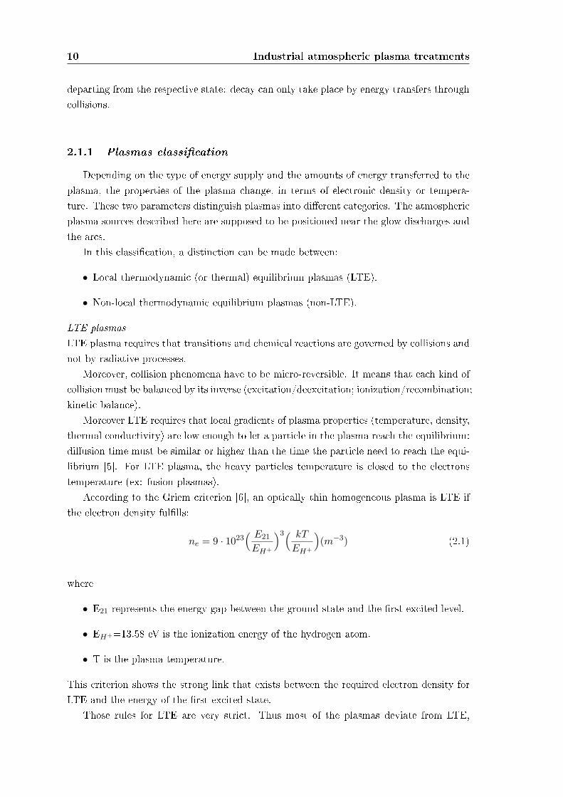
According to the Griem criterion [6], an optically thin homogeneous plasma is LTE ifthe electron density fullls:
ne = 9 · 1023( E21
EH+
)3( kT
EH+
)(m−3) (2.1)
where
• E21 represents the energy gap between the ground state and the rst excited level.
• EH+=13.58 eV is the ionization energy of the hydrogen atom.
• T is the plasma temperature.
This criterion shows the strong link that exists between the required electron density forLTE and the energy of the rst excited state.
Those rules for LTE are very strict. Thus most of the plasmas deviate from LTE,
2.1 Introduction 11
especially all types of low density plasma in laboratories.
Non-LTE plasmasDeparture from Boltzmann distribution for the density of excited atoms can explain thedeviation from LTE. Indeed, for low-lying levels, the electron-induced de-excitation rate ofthe atom is generally lower than the corresponding electron-induced excitation rate becauseof a signicant radiative de-excitation rate. Another deviation from LTE is inducedby the mass dierence between electrons and heavy particles. Electrons move very fastwhereas heavy particles can be considered static: electrons are thus likely to govern colli-sions and transitions phenomena. Deviations from LTE are also due to strong gradients inthe plasma and the associated diusion eects.
It has been shown that the LTE distribution can be partial. For example, LTE can beveried for the levels close to ionization threshold [7] (e.g., 5p levels and higher, in argonplasma): such plasmas are pLTE (partial LTE).
The non-LTE plasmas can be described by a two temperature model: an electron tem-perature (Te) and a heavy particle temperature (Th). Regarding the huge mass dierencebetween electrons and heavy particles, the plasma temperature (or gas temperature) is xedby Th. The higher the departure from LTE, the higher the dierence between Te and Th is.
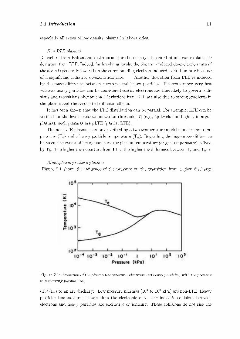
Atmospheric pressure plasmasFigure 2.1 shows the inuence of the pressure on the transition from a glow discharge
Figure 2.1: Evolution of the plasma temperature (electrons and heavy particles) with the pressurein a mercury plasma arc.
(Te>Th) to an arc discharge. Low pressure plasmas (104 to 102 kPa) are non-LTE. Heavyparticles temperature is lower than the electronic one. The inelastic collisions betweenelectrons and heavy particles are excitative or ionizing. These collisions do not rise the
12 Industrial atmospheric plasma treatments
heavy particles temperature.When the pressure becomes higher, collisions intensify. They induce both plasma
chemistry (by inelastic collisions) and heavy particles heating (by elastic collisions). Thedierence between Te and Th is reduced: plasma state becomes closer to LTE but doesnot reach it. The signicant gradient of properties in plasma restricts a particle, movingin the discharge, achieving equilibrium.
The density of the feeding power inuences a lot the plasma state (LTE or not). Onthe whole, a high power density induces LTE plasmas (e.g. arc plasmas) whereas non-LTEplasmas are favored by either a low density of feeding power or a pulsed power supply. Inthis latter case, the short pulse duration prevents the equilibrium state from establishing.
Finally, it is important to note that an atmospheric plasma jet can be divided in twozones:
• a central zone or plasma core which is LTE.
• a peripheral zone which is non-LTE. In this plume, heavy particles temperature ismuch lower than electrons one.
Indeed, for a free-burning argon arc [6], operating conditions (a pressure of 300 kPa, cur-rents of 300 to 400 A) are necessary to reach a LTE state in the central portion. Theseconditions lead to an electron density of 1024 m−3 in the center. Departures from LTEoccur in the outer regions of such arcs where the electron density decreases below 1024
m−3.Thus, the local thermodynamic equilibrium is a primordial notion since it induces the
temperature of the plasma. It strongly depends on the kind of plasma source and is deter-mining for its applications.
2.1.2 Overview of various atmospheric plasma sources
The excitation frequency is important since it inuences the behavior of the electronsand the ions.
The atmospheric plasma sources can be classied regarding their excitation mode.Three groups are then highlighted:
• the DC (direct current) and low frequency discharges;
• the plasmas which are ignited by radio frequency waves;
• the microwave discharges.
Examples of various atmospheric plasma sources
X Corona discharge [7] is a non-LTE discharge with low current density. The deviceconsists of a cathode-wire and an anode (the treated material), the DC power supply is
2.1 Introduction 13
pulsed. The plasma creates a lighting crown around the wire: that is why this dischargeis called "Corona".
When a negative high voltage is applied to the wire, the discharge is a negative corona.
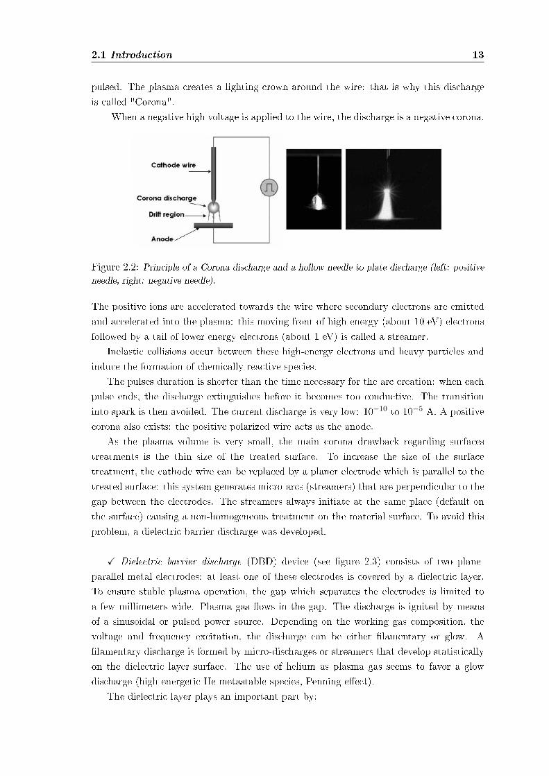
Figure 2.2: Principle of a Corona discharge and a hollow needle to plate discharge (left: positiveneedle, right: negative needle).
The positive ions are accelerated towards the wire where secondary electrons are emittedand accelerated into the plasma: this moving front of high-energy (about 10 eV) electronsfollowed by a tail of lower energy electrons (about 1 eV) is called a streamer.
Inelastic collisions occur between these high-energy electrons and heavy particles andinduce the formation of chemically reactive species.
The pulses duration is shorter than the time necessary for the arc creation: when eachpulse ends, the discharge extinguishes before it becomes too conductive. The transitioninto spark is then avoided. The current discharge is very low: 10−10 to 10−5 A. A positivecorona also exists: the positive polarized wire acts as the anode.
As the plasma volume is very small, the main corona drawback regarding surfacestreatments is the thin size of the treated surface. To increase the size of the surfacetreatment, the cathode wire can be replaced by a planer electrode which is parallel to thetreated surface: this system generates micro-arcs (streamers) that are perpendicular to thegap between the electrodes. The streamers always initiate at the same place (default onthe surface) causing a non-homogeneous treatment on the material surface. To avoid thisproblem, a dielectric barrier discharge was developed.
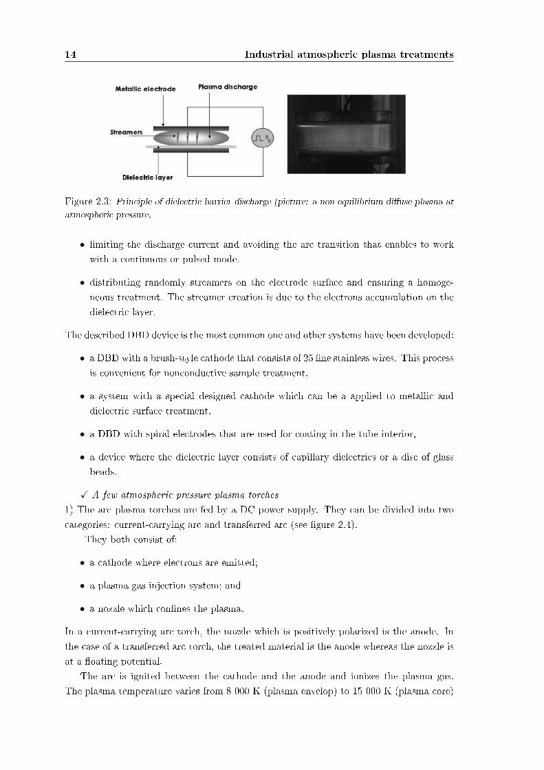
X Dielectric barrier discharge (DBD) device (see gure 2.3) consists of two plane-parallel metal electrodes: at least one of these electrodes is covered by a dielectric layer.To ensure stable plasma operation, the gap which separates the electrodes is limited toa few millimeters wide. Plasma gas ows in the gap. The discharge is ignited by meansof a sinusoidal or pulsed power source. Depending on the working gas composition, thevoltage and frequency excitation, the discharge can be either lamentary or glow. Alamentary discharge is formed by micro-discharges or streamers that develop statisticallyon the dielectric layer surface. The use of helium as plasma gas seems to favor a glowdischarge (high energetic He metastable species, Penning eect).
The dielectric layer plays an important part by:
14 Industrial atmospheric plasma treatments
Figure 2.3: Principle of dielectric barrier discharge (picture: a non equilibrium diuse plasma atatmospheric pressure.
• limiting the discharge current and avoiding the arc transition that enables to workwith a continuous or pulsed mode.
• distributing randomly streamers on the electrode surface and ensuring a homoge-neous treatment. The streamer creation is due to the electrons accumulation on thedielectric layer.
The described DBD device is the most common one and other systems have been developed:
• a DBD with a brush-style cathode that consists of 25 ne stainless wires. This processis convenient for nonconductive sample treatment,
• a system with a special designed cathode which can be a applied to metallic anddielectric surface treatment,
• a DBD with spiral electrodes that are used for coating in the tube interior,
• a device where the dielectric layer consists of capillary dielectrics or a disc of glassbeads.
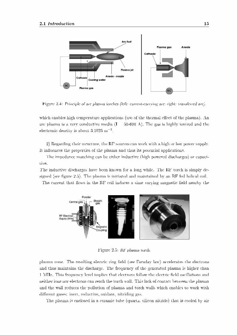
X A few atmospheric pressure plasma torches1) The arc plasma torches are fed by a DC power supply. They can be divided into twocategories: current-carrying arc and transferred arc (see gure 2.4).
They both consist of:
• a cathode where electrons are emitted;
• a plasma gas injection system; and
• a nozzle which connes the plasma.
In a current-carrying arc torch, the nozzle which is positively polarized is the anode. Inthe case of a transferred arc torch, the treated material is the anode whereas the nozzle isat a oating potential.
The arc is ignited between the cathode and the anode and ionizes the plasma gas.The plasma temperature varies from 8 000 K (plasma envelop) to 15 000 K (plasma core)
2.1 Introduction 15
Figure 2.4: Principle of arc plasma torches (left: current-carrying arc; right: transferred arc).
which enables high temperature applications (use of the thermal eect of the plasma). Anarc plasma is a very conductive media (I = 50-600 A). The gas is highly ionized and theelectronic density is about 3.1023 m−3.
2) Regarding their structure, the RF sources can work with a high or low power supply.It inuences the properties of the plasma and thus its potential applications.
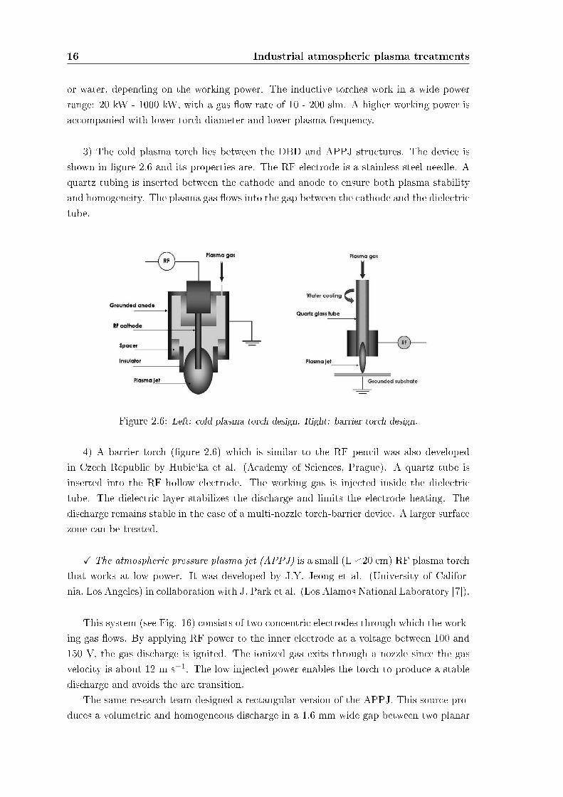
The impedance matching can be either inductive (high powered discharges) or capaci-tive.The inductive discharges have been known for a long while. The RF torch is simply de-signed (see gure 2.5). The plasma is initiated and maintained by an RF fed helical coil.The current that ows in the RF coil induces a time varying magnetic eld nearby the
Figure 2.5: RF plasma torch.
plasma zone. The resulting electric ring eld (see Faraday law) accelerates the electronsand thus maintains the discharge. The frequency of the generated plasma is higher than1 MHz. This frequency level implies that electrons follow the electric eld oscillations andneither ions nor electrons can reach the torch wall. This lack of contact between the plasmaand the wall reduces the pollution of plasma and torch walls which enables to work withdierent gases: inert, reductive, oxidant, nitriding gas.
The plasma is enclosed in a ceramic tube (quartz, silicon nitride) that is cooled by air
16 Industrial atmospheric plasma treatments
or water, depending on the working power. The inductive torches work in a wide powerrange: 20 kW - 1000 kW, with a gas ow rate of 10 - 200 slm. A higher working power isaccompanied with lower torch diameter and lower plasma frequency.
3) The cold plasma torch lies between the DBD and APPJ structures. The device isshown in gure 2.6 and its properties are. The RF electrode is a stainless-steel needle. Aquartz tubing is inserted between the cathode and anode to ensure both plasma stabilityand homogeneity. The plasma gas ows into the gap between the cathode and the dielectrictube.
Figure 2.6: Left: cold plasma torch design. Right: barrier torch design.
4) A barrier torch (gure 2.6) which is similar to the RF pencil was also developedin Czech Republic by Hubie`ka et al. (Academy of Sciences, Prague). A quartz tube isinserted into the RF hollow electrode. The working gas is injected inside the dielectrictube. The dielectric layer stabilizes the discharge and limits the electrode heating. Thedischarge remains stable in the case of a multi-nozzle torch-barrier device. A larger surfacezone can be treated.
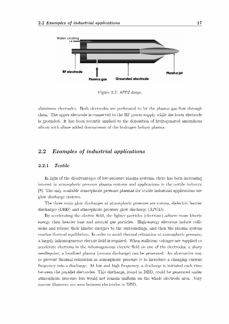
X The atmospheric pressure plasma jet (APPJ) is a small (L <20 cm) RF plasma torchthat works at low power. It was developed by J.Y. Jeong et al. (University of Califor-nia, Los Angeles) in collaboration with J. Park et al. (Los Alamos National Laboratory [7]).
This system (see Fig. 16) consists of two concentric electrodes through which the work-ing gas ows. By applying RF power to the inner electrode at a voltage between 100 and150 V, the gas discharge is ignited. The ionized gas exits through a nozzle since the gasvelocity is about 12 m s−1. The low injected power enables the torch to produce a stabledischarge and avoids the arc transition.
The same research team designed a rectangular version of the APPJ. This source pro-duces a volumetric and homogeneous discharge in a 1.6 mm wide gap between two planar
2.2 Examples of industrial applications 17
Figure 2.7: APPJ design.
aluminum electrodes. Both electrodes are perforated to let the plasma gas ow throughthem. The upper electrode is connected to the RF power supply while the lower electrodeis grounded. It has been recently applied to the deposition of hydrogenated amorphoussilicon with silane added downstream of the hydrogen-helium plasma.
2.2 Examples of industrial applications
2.2.1 Textile
In light of the disadvantages of low-pressure plasma systems, there has been increasinginterest in atmospheric pressure plasma systems and applications in the textile industry[8]. The only available atmospheric pressure plasmas for textile industrial applications areglow discharge systems.
The three main glow discharges at atmospheric pressure are corona, dielectric barrierdischarges (DBD) and atmospheric pressure glow discharge (APGD).
By accelerating the electric eld, the lighter particles (electrons) achieve more kineticenergy than heavier ions and neutral gas particles. High-energy electrons induce colli-sions and release their kinetic energies to the surroundings, and then the plasma systemreaches thermal equilibrium. In order to avoid thermal relaxation at atmospheric pressure,a largely inhomogeneous electric eld is required. When sucient voltages are supplied toaccelerate electrons in the inhomogeneous electric eld on one of the electrodes, a sharpneedlepoint, a localized plasma (corona discharge) can be generated. An alternative wayto prevent thermal relaxation at atmospheric pressure is to introduce a changing currentfrequency into a discharge. At low and high frequency, a discharge is initiated each timebetween the parallel electrodes. This discharge, found in DBD, could be generated underatmospheric pressure but would not remain uniform on the whole electrode area. Verynarrow laments are seen between electrodes in DBD.
18 Industrial atmospheric plasma treatments
Corona Systems for Textile Applications
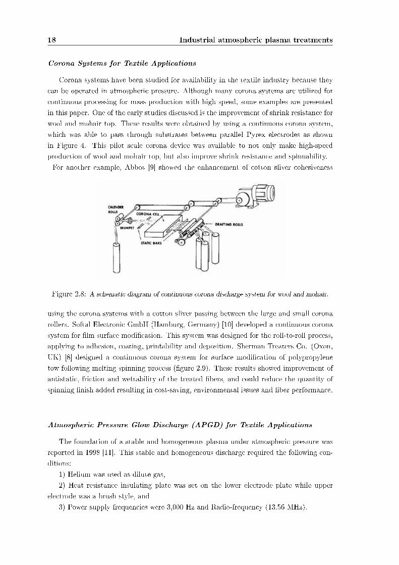
Corona systems have been studied for availability in the textile industry because theycan be operated in atmospheric pressure. Although many corona systems are utilized forcontinuous processing for mass production with high speed, some examples are presentedin this paper. One of the early studies discussed is the improvement of shrink resistance forwool and mohair top. These results were obtained by using a continuous corona system,which was able to pass through substrates between parallel Pyrex electrodes as shownin Figure 4. This pilot scale corona device was available to not only make high-speedproduction of wool and mohair top, but also improve shrink-resistance and spinnability.For another example, Abbot [9] showed the enhancement of cotton sliver cohesiveness
Figure 2.8: A schematic diagram of continuous corona discharge system for wool and mohair.
using the corona systems with a cotton sliver passing between the large and small coronarollers. Softal Electronic GmbH (Hamburg, Germany) [10] developed a continuous coronasystem for lm surface modication. This system was designed for the roll-to-roll process,applying to adhesion, coating, printability and deposition. Sherman Treaters Co. (Oxon,UK) [8] designed a continuous corona system for surface modication of polypropylenetow following melting spinning process (gure 2.9). These results showed improvement ofantistatic, friction and wettability of the treated bers, and could reduce the quantity ofspinning nish added resulting in cost-saving, environmental issues and ber performance.
Atmospheric Pressure Glow Discharge (APGD) for Textile Applications
The foundation of a stable and homogeneous plasma under atmospheric pressure wasreported in 1998 [11]. This stable and homogeneous discharge required the following con-ditions:
1) Helium was used as dilute gas,2) Heat resistance insulating plate was set on the lower electrode plate while upper
electrode was a brush style, and3) Power supply frequencies were 3,000 Hz and Radio-frequency (13.56 MHz).
2.2 Examples of industrial applications 19
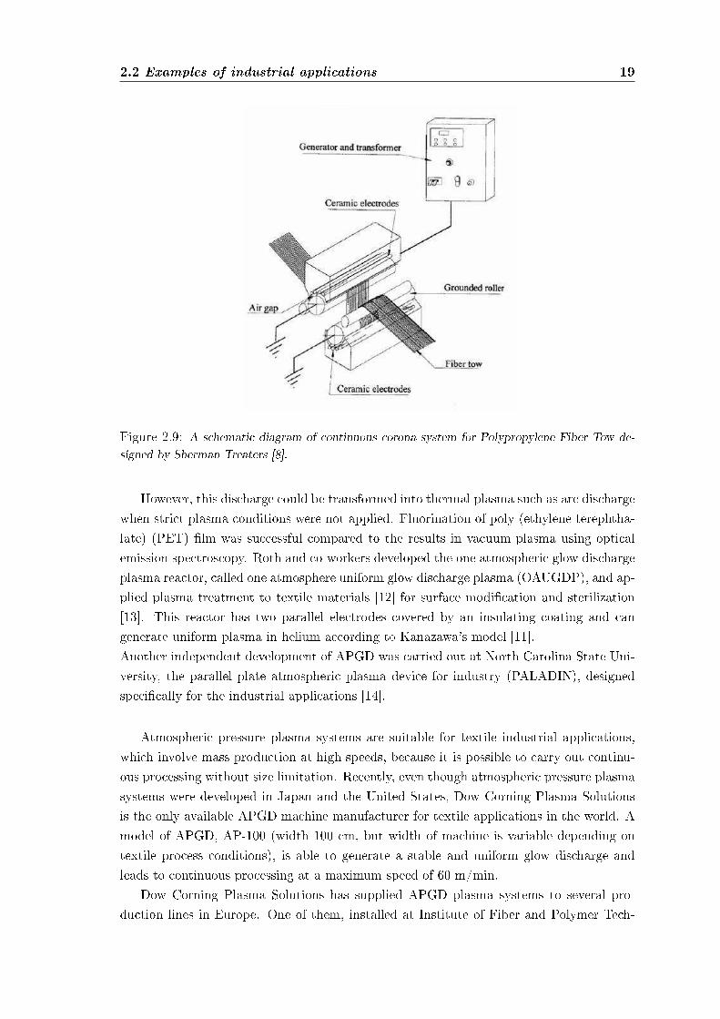
Figure 2.9: A schematic diagram of continuous corona system for Polypropylene Fiber Tow de-signed by Sherman Treaters [8].
However, this discharge could be transformed into thermal plasma such as arc dischargewhen strict plasma conditions were not applied. Fluorination of poly (ethylene terephtha-late) (PET) lm was successful compared to the results in vacuum plasma using opticalemission spectroscopy. Roth and co-workers developed the one atmospheric glow dischargeplasma reactor, called one atmosphere uniform glow discharge plasma (OAUGDP), and ap-plied plasma treatment to textile materials [12] for surface modication and sterilization[13]. This reactor has two parallel electrodes covered by an insulating coating and cangenerate uniform plasma in helium according to Kanazawa's model [11].Another independent development of APGD was carried out at North Carolina State Uni-versity, the parallel plate atmospheric plasma device for industry (PALADIN), designedspecically for the industrial applications [14].
Atmospheric pressure plasma systems are suitable for textile industrial applications,which involve mass production at high speeds, because it is possible to carry out continu-ous processing without size limitation. Recently, even though atmospheric pressure plasmasystems were developed in Japan and the United States, Dow Corning Plasma Solutionsis the only available APGD machine manufacturer for textile applications in the world. Amodel of APGD, AP-100 (width 100 cm, but width of machine is variable depending ontextile process conditions), is able to generate a stable and uniform glow discharge andleads to continuous processing at a maximum speed of 60 m/min.
Dow Corning Plasma Solutions has supplied APGD plasma systems to several pro-duction lines in Europe. One of them, installed at Institute of Fiber and Polymer Tech-
20 Industrial atmospheric plasma treatments
nology Research (IFP, Sweden), is applied to adhesion enhancement of polymer coatings(Almedahl AB, Sweden), surface modication of automobile textiles (Borgstena TextileSweden AB, Sweden), increasing hydrophobicity of cellulose based materials, and improve-ment of adhesion of polymer materials (SCA Hygiene Products AB, Sweden). In German,Kirchho GmbH and Co. has been applying APGD plasma system to anti-shrinkage n-ishing. The same APGD system at Polisilk S.A. in Spain is being used to improve bindingproperties of polypropylene-based coating. In addition, Plasma Ireland supplied anotherAPGD system to Scapa Group in England for printing applications.
Plasma Applications to Textile Processing
Wettability EnhancementThe wettability enhancement of polymeric surfaces can be obtained easily by plasma treat-ment in oxygen containing gas. However, after exposure to air, the wettability is notdurable due to the ageing process. For the textile applications of wettability enhancement,increased durability has been obtained using plasma graft polymerization techniques. Themonomers used in plasma graft polymerization for wettability enhancement are acrylic acid,nitro compounds, 2-hydroxyethyl methacrylate (HEMA), methyl methacrylate (MMA),acrylamide (AAm) and acrylonitrile [8].
In 1971, the rst commercial application of plasma graft polymerization for wettabilityenhancement on fabrics was conducted by Bradley [15]. After surface functionalizationby argon plasma for PET fabrics, the acrylic acid monomer was introduced into vacuumchamber leading to uniform grafting polymerization. This technique could render PETfabrics as wettable as cotton and improve moisture retention and washing durability. Inaddition, handle properties of fabrics were improved without alteration bulk properties.Cotton fabrics treated by this technique showed better hand properties obtained.
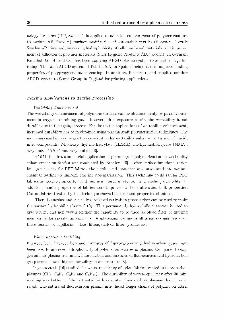
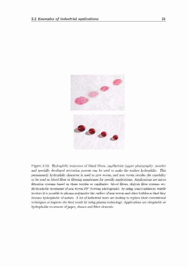
There is another and specially developed activation process that can be used to makethe surface hydrophilic (gure 2.10). This permanently hydrophilic character is used togive woven, and non woven textiles the capability to be used as blood lter or lteringmembranes for specic applications. Applications are micro ltration systems based onthese textiles or capillaries: blood lters, dialysis lter systems etc.
Water Repellent FinishingFluorocarbon, hydrocarbon and mixtures of uorocarbon and hydrocarbon gases havebeen used to increase hydrophobicity of polymer substrates in plasma. Compared to oxy-gen and air plasma treatment, uorocarbon and mixtures of uorocarbon and hydrocarbongas plasma showed higher durability in air exposure [8].
Iriyama et al. [16] studied the water-repellency of nylon fabrics treated in uorocarbonplasmas (CF4, C2F4, C3F6 and C6F14). The durability of water-repellency after 30 min.washing was better in fabrics treated with saturated uorocarbon plasmas than unsatu-rated. The saturated uorocarbon plasma introduced longer chains of polymer on fabric
2.2 Examples of industrial applications 21
Figure 2.10: Hydrophilic treatment of blood lters, capillarities (upper photograph): anotherand specially developed activation process can be used to make the surface hydrophilic. Thispermanently hydrophilic character is used to give woven, and non woven textiles the capabilityto be used as blood lter or ltering membranes for specic applications. Applications are microltration systems based on these textiles or capillaries: blood lters, dialysis lter systems etc.Hydrophobic treatment of non woven PP (bottom photograph): by using semi-continuous textiletreaters it is possible to plasma polymerize the surface of non woven and other textiles so that theybecome hydrophobic of nature. A lot of industrial users are looking to replace their conventionaltechniques or improve the nal result by using plasma technology. Applications are oleophobic orhydrophobic treatment of paper, tissues and lter elements.
22 Industrial atmospheric plasma treatments
surface (gure 2.10), leading to better hydrophobicity and durability. Wang et al. [17]found similar results from plasma treatment on PET lm with mixtures of uorocarbonand methane.
McCord et al. [18] found that the uorocarbon functional group, -CF3, played an im-portant role in increasing water-repellency.
Anti-shrinkage FinishingAnti-shrinkage nishing using plasma treatment is the rst successful commercialized tech-nique for the textile industry. The rst attempt at anti-shrinkage nishing was a coronatreatment for wool fabrics [8]. Wool garments treated by corona showed better shrink re-sistance and stability than untreated. Thorsen et al. [19] suggested that corona treatmentcould be applied to mass production of wool fabric to improve shrink resistance. Comparedto corona treatment, the eciency of anti-shrinkage in plasma treatment shows better ef-fect. Recently, low-pressure plasma and corona are available for anti-shrinkage nishing intextile industry. Plasma treatment is considered an environmentally friendly alternativeto the conventional anti-shrinkage nishing, wool chlorination.
Regardless, further studies are still needed to apply plasma treatment to industrialproduction for anti-shrinkage nishing as well as enzymatic treatment, which is anotherpossible environmentally friendly method for anti-shrinkage nishing.
Oxygen was known as the most eective gas for shrink proong of wool fabrics madefrom plasma-treated yarns [8].
DesizingThe application of size to warp yarns before weaving plays an important role in enhance-ment of weaving eciency due to an increase of yarn strength and reduction of yarnhairiness. Also, it is important to remove size after weaving for further processes, dyeingand nishing. The conventional desizing process is conducted by washing in hot waterbath.
Regardless of high temperature, complete removal of size on fabrics is impossible due toredeposited sizes on yarns during the desizing process, resulting in poor bleaching, dyeingand printing. Moreover, the desizing waste is a major concern of pollution world-wide,even though a recycling technique is available.
Plasma desizing was performed as a novel technique to solve the environmental problemof desizing [8]. The plasma desizing process consisted of two steps: gas plasma treatmenton the sized fabric and washing in solution. Compared to hydrogen peroxide desizing,plasma treatment plus cold-water washing showed better size removal on cotton fabrics.Oxygen plasma was more eective in desizing than either air or nitrogen. Two possibleplasma eects are involved in the plasma desizing. First one is gas vaporization of sizes bythe etching eect of plasma.
The second one is hydrophilic functionalization of size molecules, possible in conjunc-tion with either chain scission or cross-linking. The increase in hydrophilic groups may
2.2 Examples of industrial applications 23
lead to higher solubility in wash solution.
Flame Retardant FinishingFlame retardant nishing of textiles has been accomplished via plasma treatment. Asone of initial studies for ame retardant nishing on textiles, researchers studied ameretardant nishing on natural and synthetic fabrics. The fabrics pre-absorbed with phos-phorus and halogen containing monomers were exposed to nitrogen low-pressure plasma,leading to graft polymerization on fabric surface. The graft polymerization by plasma withphosphorus and halogen containing monomers improved the ame retardant properties offabrics.
In addition, it was proposed that plasma application of ame retardant nishing couldhave economical and environmental advantages compared to conventional wet-chemicalnishing processes. For ame retardant nishing for cotton fabrics, cotton fabrics treatedby argon plasma with THPOH/NH3 and H2O2 washing were durable to 50 launderingsand launderings with chlorine bleaching.
Adhesion EnhancementMost of composite materials, including UHMPE (ultrahigh modulus polyethylene), PPTA(poly(p-phenylene terephthalate) and carbon bers, have excellent mechanical properties.However, chemical inertness and smoothness of their surfaces can be a serious problem toapply to resin matrix for composite applications. Compared to conventional wet chemicalsurface modication, plasma techniques can overcome the disadvantages of high perfor-mance bers easily and improve adhesion to resin matrix without altering physical prop-erties.
Ultrahigh-modulus polyethylene (UHMPE) bers such as Spectra. bers do not formstrong bonds with most commercially available matrix materials due to their inert chem-ical structure. Low-pressure plasma treatments have been shown to greatly enhance thebonding between UHMPE ber and resin matrices such as epoxy and vinyl ester resins[20].
The plasma treatment created not only micro-roughness on the surface of UHMPEbers, resulting in a better mechanical interlocking of the ber surface to resin matrix,but also functional groups, leading to chemical interfacial bonding between the ber andmatrix.
Dyeability EnhancementDyeing in textile industry requires the development of environmentally friendly and eco-nomic processes due to pollution and economic limitations. Plasma techniques have beenstudied to replace or aid the conventional wet dyeing process. The initial approach ofplasma was corona treatment.
As an example, Wakida et al. [21] showed the possibilities of atmospheric pressureplasma for wool fabric dyeing applications. The atmospheric pressure plasma treatment
24 Industrial atmospheric plasma treatments
with a mixture of helium and argon was very eective on the reduction of half-dyeing timeand an increase of dye exhaustion with acid dyes.
SterilizationSterilization processes are designed to destroy viable microorganisms before biomaterialcontact with living organisms. In general, either a physical or chemical process or both arecarried out sterilization. The conventional sterilization methods including heat, radiation,and chemical treatment can terminate the microorganisms [8]. Heat treatment is an easymethod but bacteria with a pore could survive at high temperature and under some con-ditions. Additionally, heat treatment is not acceptable to low-melting polymer materialsand it needs a relatively long period treat time. Ethylene oxide (ETO) is used as a chem-ical treatment to sterilize many polymeric medical products. However, ETO is not only ahighly toxic gas causing cancer but easily absorbed in plastic materials. Gamma radiationand X-ray can exterminate bacteria or viruses by breaking bonds inside the bacteria cellsand virus capsides. However, some of microorganisms resist radiation, and radiation causesundesirable changes of substrate.
Because the power density of atmospheric plasma is not high, it does not alter the bulkproperties of substrates where bacteria and viruses live. Also, the successful design of aremote exposure reactor can eliminate many constraints of workpiece size and shape.
Recently, the atmospheric pressure plasma has been investigated as novel sterilizationtechnique [13]. One of successful designs is one atmosphere uniform glow discharge plasma(OAUGDP, University of Tennessee, Knoxville (UTK)).
Koulik et al. [22] proposed the mechanism of sterilization under atmospheric pressureplasma as following;
1) Plasmochemical reaction: oxidation and etching,2) Electron bombardment,3) UV radiation,4) Surface ablation and5) Chemical reaction after plasma treatment.
As an italian living reality the University of Milano-Bicocca, together with the RegioneLombardia and the Fondazione Cariplo, supported the creation of a Centre of Excellenceon Plasma Applications as depicted in gure 2.11.
Mainly they work on:
• Plasma Processing for polymers, gas sterilization and VOC abatements; coating,plasma spray, dusty plasmas;
• Plasma Processing for Energy: hydrogen production and waste treatments by plasma,plasma Fuel Converter (PFC) for producing hydrogen rich mixtures, plasma torchfor waste treatments;
• Plasma processing for biomedical applications

2.2 Examples of industrial applications 25
Technology on atmospheric plasma:A reality for the textile field
CLAUDIA RICCARDI, PlasmaPrometeo, Università degli Studi di Milano-Bicocca
MARIA ROSARIA MASSAFRA, Stazione Sperimentale per la Seta
STEFANO FORT, Arioli s.p.a. [email protected] www.arioli.biz
A new plasma technology highly innovative in the field of superficial treatments of the materials,
it is based on a DBD electric discharge. (Dielectric barrier discharge)
Radicals, active chemical species and loaded species are produced and with them it is possible to realize processes of
non-conventional superficial modification.
NANOTECHNOLOGYThe modifications applied to the surface are on nanometre scale at room temperature.
THE PROCESSESThe superficial modifications take place thanks to the high plasma reactivity and processes trigger.
Physical type (bombing of the surface)
Chemical type (reactions with radicals).
ADVANTAGESINNOVATION:
It generates innovative materials and new surface properties.
It does not modify the bulk property of the material.
ENVIRONMENT:
Negligible quantity of chemicals.
Dry process, which does not require solvents or chemicals dangerous for the environment.
The DBD technology with respect to the plasma common technologies operates at ATMOSPHERIC PRESSURE
Production processes in continuous way.
Process times are highly reduced.
All disadvantages due to the preparation of vacuum plants are avoided.
It is not necessary to use seal devices.
ENERGY SAVING AND A LOWER ENVINROMENTAL IMPACT.
THE APPLICATIONS THE FABRIC
THE PROTOTYPE
Increase of wettability.
Increase of hydrophilicity
Water-repellent and oil-repellent surfaces achieved.
Biocompatibility (antibacterial properties of adhesion and affinity to proteins and other bio molecules).
Dyeable (increase of dyeing speed).
Print (increase of absorbed colour quantity by the textile fibres).
Adhesion (increase of spreading adhesion with specific compounds.)
It is applied to fabrics and yarns of natural and artificial fibres without modifying it’s bulk properties:
The organoleptic properties and the transpiration are unchanged.
Fabrics with multifunctional properties can be obtained.
They can be applied to all textile-working phases from the fibre until fabric finishing process.
They can be easily introduced into the productive processes
• It is based on DBD discharges.
• It operates under atmospheric pressure with air or inert gas and several gas mixtures.
• It produces plasma between two or more electrodes in which the fabric runs.
• Different speeds (1-60 m/min).
• Treatment on one or both fabric sides.
• Fabric width up to 400 cm.
With the realized prototype, it is therefore possible to carry on experiments and to realize applications at industrial level on various technical and traditional textile products for furnishing and clothing use.
Reaction of atoms insertion or complete chemical groups ( grafting)
Generation of free radicals on the surface.( Attivazione).
Polymers deposition in a gaseous phase as thin layer adherent to the surface (film deposition)
Superficial ablation of the material (etching).
Realised for the project “Metadistretti per l'eccellenza Lombarda”, with “ARIOLI s.p.a.”, textile machinery enterprise, as leader company, together with the research institutes “Stazione Sperimentale per la Seta” and “Plasma Prometeo” of “Università degli Studi – Milano-Bicocca”
At the moment: : excellent results with water repellence and hydrophilic.Research projects for the development of other processes of textile interest are in progress..
The materials that can be functionalised are:Polypropylene, polyethylene polyester, nylon, natural textile fibres, etc.…
Fabrics for clothing. Fabrics for furnishings Technical fabrics (filtration, medical, pharmaceutical). Non-woven fabrics.
Figure 2.11: To promote the Research and the Technological Transfer in the eld of PlasmaApplications, the University of Milano-Bicocca, together with the Regione Lombardia and theFondazione Cariplo, supported the creation of a Centre of Excellence on Plasma Applications.The Centre of Excellence PLASMAPROMETEO was established on February 12 th 2004 on thebasis of an agreement between the University of Milano-Bicocca and the Regione Lombardia. Theaims of the Centre is to promote Technological Transfer and training to Small Medium Enterprises.(http://www.plasmaprometeo.unimib.it/history.php)
26 Industrial atmospheric plasma treatments
• Plasma Processing for Cultural Heritage
• Technological Transfer to Industries
• Development of semi-industrial prototypes
• Formation and Technical assistance
• Technical and economical evaluation for industrialization of new plasma technologies
2.2.2 Bottles and Displays
Pretreatment with atmospheric pressure plasma is arousing ever more interest amongusers who require microscopically ne precleaning and high activation of surfaces prior tothe painting process. Whether it is a light switch or mobile phone housing, display orperfume bottle manufacturers are putting ever more eort into improving their surfacecoating processes. This also requires action to optimize pretreatment.
Pretreatment processes range from ionization or ame treatment through wet chemicalprocesses, power washing and use of primers right up to dusting with ostrich feathers.Despite the sometimes high investments made, the proportion of reject parts in productioncaused by painting over particles of dust is often well above 10 %.
Static charging of surfaces, tiny but still unacceptable remnants of ne dust in lessaccessible areas or environmental pollution are the most common problems in the afore-mentioned processes.
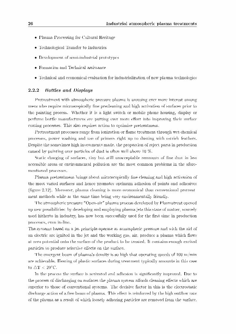
Plasma pretreatment brings about microscopically ne cleaning and high activation ofthe most varied surfaces and hence promotes optimum adhesion of paints and adhesives(gure 2.12). Moreover, plasma cleaning is more economical than conventional pretreat-ment methods while at the same time being very environmentally friendly.
The atmospheric pressure "Open-air" plasma process developed by Plasmatreat openedup new possibilities: by developing and employing plasma jets this state of matter, scarcelyused hitherto in industry, has now been successfully used for the rst time in productionprocesses, even in-line.The systems based on a jet principle operate at atmospheric pressure and with the aid ofan electric arc ignited in the jet and the working gas, air, produce a plasma which owsat zero potential onto the surface of the product to be treated. It contains enough excitedparticles to produce selective eects on the surface.
The emergent beam of plasma's density is so high that operating speeds of 100 m/minare achievable. Heating of plastic surfaces during treatment typically amounts in this caseto 4T < 20C.
In the process the surface is activated and adhesion is signicantly improved. Due tothe process of discharging on surfaces the plasma system aords cleaning eects which aresuperior to those of conventional systems. The decisive factor in this is the electrostaticdischarge action of a free beam of plasma. This eect is reinforced by the high outow rateof the plasma as a result of which loosely adhering particles are removed from the surface.
2.2 Examples of industrial applications 27
Figure 2.12: Tantec has been oering cutting-edge and environmentally-friendly Plasma andCorona surface treatment equipment for over thirty years. Tantec develops, manufactures andmarkets innovative equipment worldwide for Plasma and Corona surface treatment of plastic com-ponents. Atmospheric Plasma treating system provides an economical solution for the cleaning andactivation of complex surfaces before further processing. Component preparation is an importantstep prior to bonding, painting, varnishing and coating processes.
28 Industrial atmospheric plasma treatments
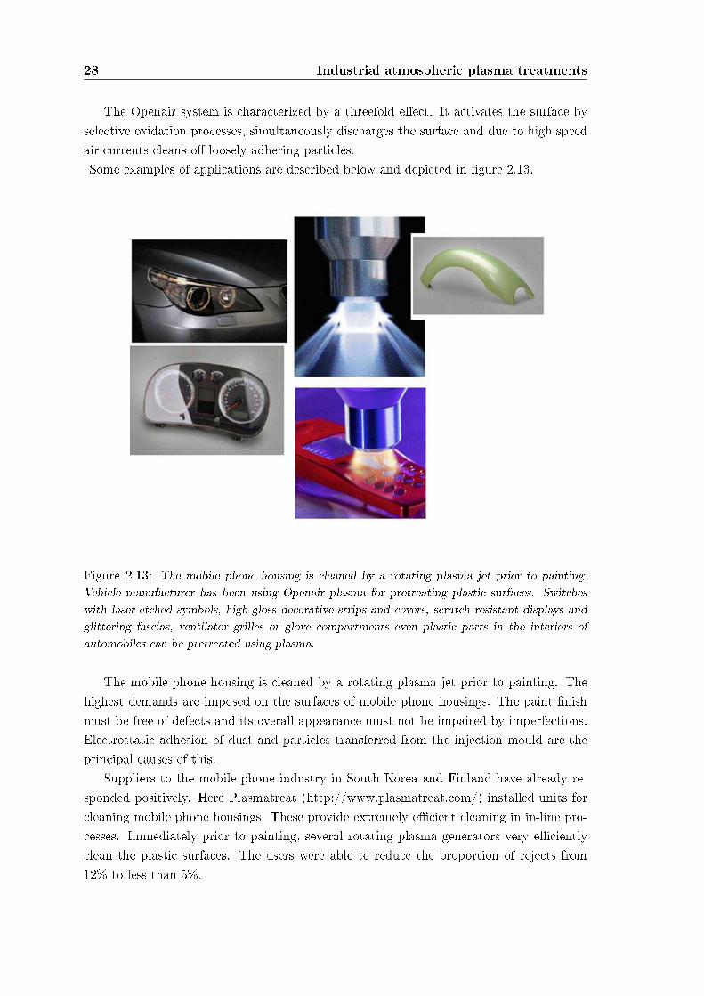
The Openair system is characterized by a threefold eect. It activates the surface byselective oxidation processes, simultaneously discharges the surface and due to high speedair currents cleans o loosely adhering particles.Some examples of applications are described below and depicted in gure 2.13.
Figure 2.13: The mobile phone housing is cleaned by a rotating plasma jet prior to painting.Vehicle manufacturer has been using Openair plasma for pretreating plastic surfaces. Switcheswith laser-etched symbols, high-gloss decorative strips and covers, scratch resistant displays andglittering fascias, ventilator grilles or glove compartments even plastic parts in the interiors ofautomobiles can be pretreated using plasma.
The mobile phone housing is cleaned by a rotating plasma jet prior to painting. Thehighest demands are imposed on the surfaces of mobile phone housings. The paint nishmust be free of defects and its overall appearance must not be impaired by imperfections.Electrostatic adhesion of dust and particles transferred from the injection mould are theprincipal causes of this.
Suppliers to the mobile phone industry in South Korea and Finland have already re-sponded positively. Here Plasmatreat (http://www.plasmatreat.com/) installed units forcleaning mobile phone housings. These provide extremely ecient cleaning in in-line pro-cesses. Immediately prior to painting, several rotating plasma generators very ecientlyclean the plastic surfaces. The users were able to reduce the proportion of rejects from12% to less than 5%.
2.2 Examples of industrial applications 29
For two years a vehicle manufacturer has been using Openair plasma for pretreatingplastic surfaces. The high demand for vehicles having expensive multiple layers of paintcaused bottlenecks in the curing ovens.
A vehicle part usually passes through many stations during the painting process. Atypical plastic part is given a coat of primer adhesion promoter, up to eight coats of paintplus a clear coat. But ovens have limited capacity. Most manufacturers have only onepaint line and one curing oven per factory. Thus, one part will travel though the sameoven from four up to nine times. Any way a manufacturer can increase capacity withoutcost-intensive procurement of new equipment results in signicant cost savings.
In the present example it is not possible to retain the same high quality appearance ofsurfaces while reducing the number of nishing coatings used. However, with the aid of theplasma treatment it was possible to dispense with the primer coating promoting adhesion.In this way the number of passes through the oven were reduced by 25% or conversely thecapacity of the oven was signicantly increased. In addition it was possible to eliminatethe entire priming process and the high costs associated with it.
Switches with laser-etched symbols, high-gloss decorative strips and covers, scratch re-sistant displays and glittering fascias, ventilator grilles or glove compartments even plasticparts in the interiors of automobiles are today provided with expensive coats of paint.
Here plasma technology can be used as a pretreatment process for these componentsboth prior to bonding as well as prior to painting. Accordingly, to cite some examples, theprocess is used for vehicle parts made by BMW and Rolls Royce.
Pretreatment with atmospheric pressure plasma, however, is not just an issue for mate-rials such as plastics or metals. It is also relevant to glass surfaces. Thus, the glass bottlesfor expensive perfumes are often painted, some even in multiple colors. The high-qualityimage of the bottles demands an immaculate surface and the most thorough cleaning ofthe material prior to the painting process. A German perfume bottle manufacturer is alsoproting from the advantages aorded by plasma technology. It has been running a plasmapretreatment installation since last year.

30 Industrial atmospheric plasma treatments
31
Chapter 3
Radio-frequency atmospheric plasmacleaning applied to niobium resonantcavities
As already mentioned atmospheric pressure plasma treatment is an emerging, very ver-satile and inexpensive technique used in various surface process such as dry etching, chem-ical modication and surface wettability change. We decided to try to ignite a resonanceatmospheric plasma into 1.5 GHz superconducting niobium cavities to perform a feasibilitystudy. The second step has been the attempt to understand what really happens to the reso-nant structure internal surface. The most powerful tool consists in the atmospheric plasmatreatment and fast rf characterization of 6 GHz small resonators.
3.1 Experimental details
The experimental set up, conceived to test atmospheric plasma treatments, consistsessentially in the rf and cryogenic systems used to test the cavity quality. The only modi-cation that has to be considered is the adding of a gas line.
3.1.1 rf apparatus
The rf apparatus we use has been already described elsewhere ([23, 24]), I just want togive the basic information to simplify the comprehension of the following sections.
Fundamental equations for rf test
During the rf tests on cold cavities the basic rf properties such as maximum acceleratinggradient (Eacc), eld emission onset, and quality factor Q0, as a function of Eacc aredetermined. These tests (that have to be performed at (or near) the critical coupling) aredone inside a cryostat where the cavity is held vertically.
32Radio-frequency atmospheric plasma cleaning applied to niobium resonant
cavities
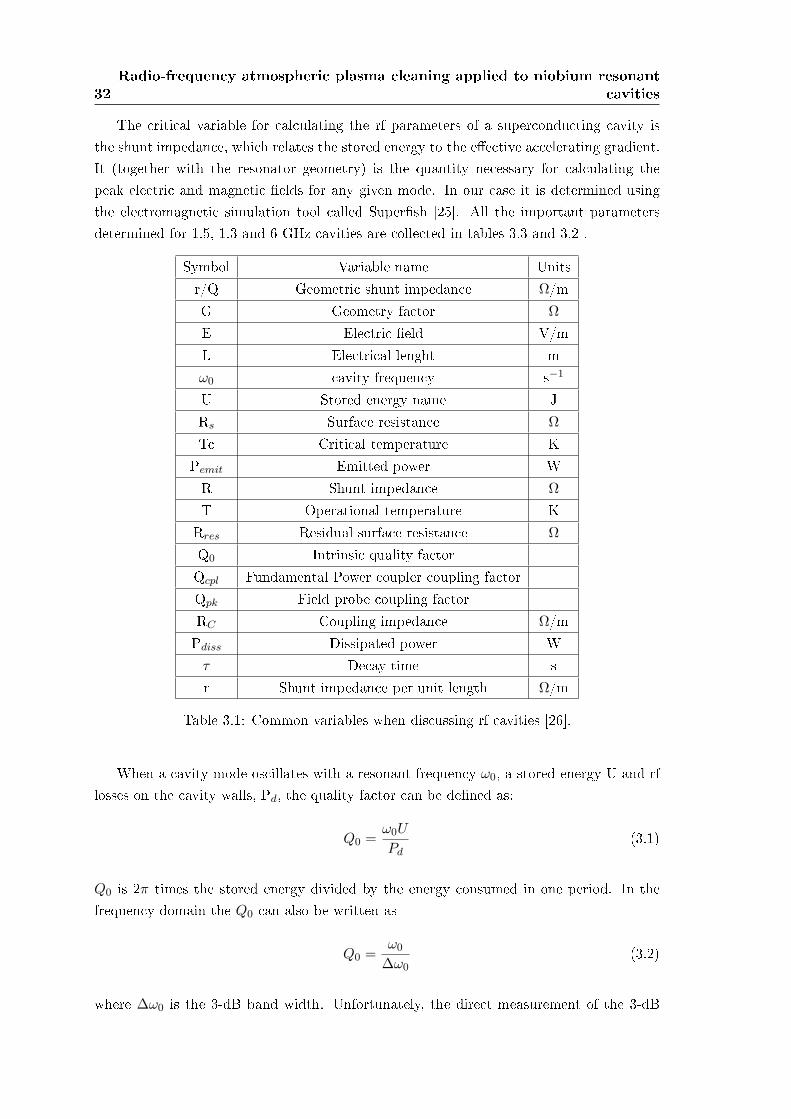
The critical variable for calculating the rf parameters of a superconducting cavity isthe shunt impedance, which relates the stored energy to the eective accelerating gradient.It (together with the resonator geometry) is the quantity necessary for calculating thepeak electric and magnetic elds for any given mode. In our case it is determined usingthe electromagnetic simulation tool called Supersh [25]. All the important parametersdetermined for 1.5, 1.3 and 6 GHz cavities are collected in tables 3.3 and 3.2 .
Symbol Variable name Unitsr/Q Geometric shunt impedance Ω/mG Geometry factor Ω
E Electric eld V/mL Electrical lenght mω0 cavity frequency s−1
U Stored energy name JRs Surface resistance Ω
Tc Critical temperature KPemit Emitted power WR Shunt impedance Ω
T Operational temperature KRres Residual surface resistance Ω
Q0 Intrinsic quality factorQcpl Fundamental Power coupler coupling factorQpk Field probe coupling factorRC Coupling impedance Ω/mPdiss Dissipated power W
τ Decay time sr Shunt impedance per unit length Ω/m
Table 3.1: Common variables when discussing rf cavities [26].
When a cavity mode oscillates with a resonant frequency ω0, a stored energy U and rflosses on the cavity walls, Pd, the quality factor can be dened as:
Q0 =ω0U
Pd(3.1)
Q0 is 2π times the stored energy divided by the energy consumed in one period. In thefrequency domain the Q0 can also be written as
Q0 =ω0
∆ω0(3.2)
where ∆ω0 is the 3-dB band width. Unfortunately, the direct measurement of the 3-dB
3.1 Experimental details 33
band width of a superconducting cavity is practically impossible, because it can attainvery small values as compared to the center frequency: some Hz or fractions of Hz outof thousands of Megahertz. This is much less than the resolution of any commerciallyavailable network or spectrum analyzer. For this reason, a time domain method must beused.
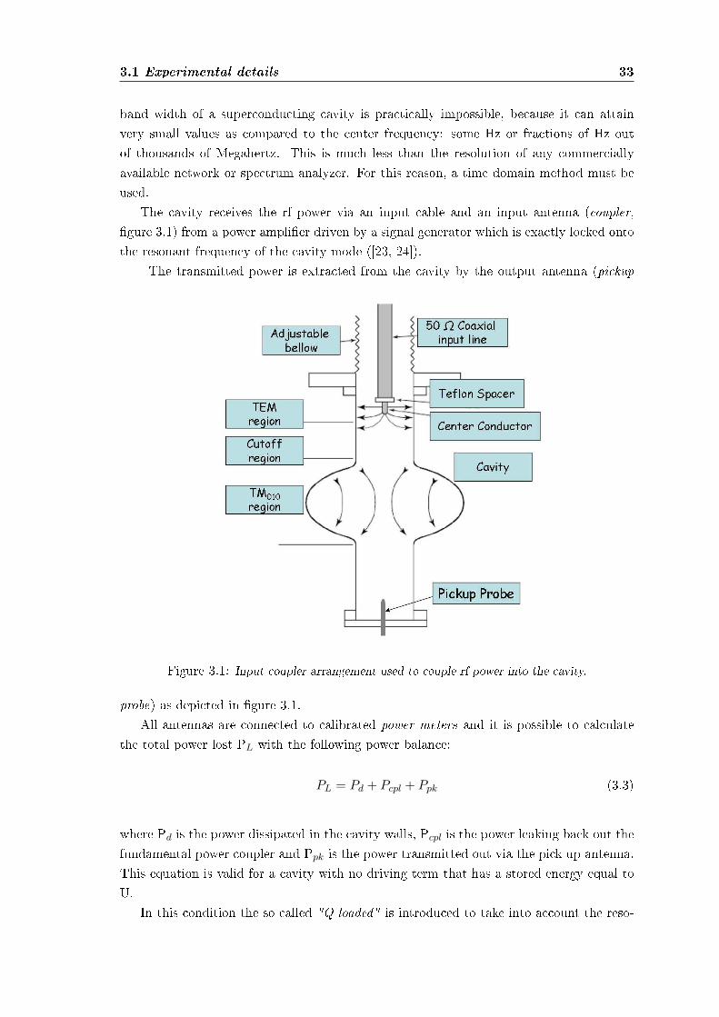
The cavity receives the rf power via an input cable and an input antenna (coupler,gure 3.1) from a power amplier driven by a signal generator which is exactly locked ontothe resonant frequency of the cavity mode ([23, 24]).
The transmitted power is extracted from the cavity by the output antenna (pickup
Figure 3.1: Input coupler arrangement used to couple rf power into the cavity.
probe) as depicted in gure 3.1.All antennas are connected to calibrated power meters and it is possible to calculate
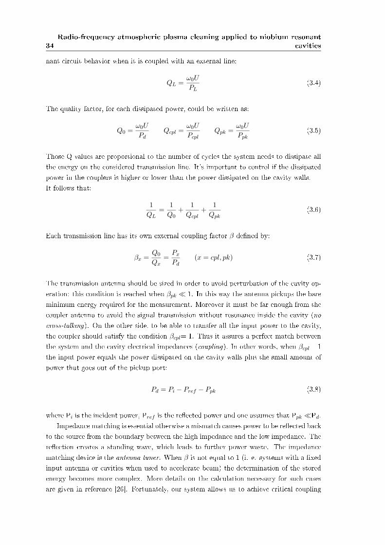
the total power lost PL with the following power balance:
PL = Pd + Pcpl + Ppk (3.3)
where Pd is the power dissipated in the cavity walls, Pcpl is the power leaking back out thefundamental power coupler and Ppk is the power transmitted out via the pick up antenna.This equation is valid for a cavity with no driving term that has a stored energy equal toU.
In this condition the so called "Q loaded" is introduced to take into account the reso-
34Radio-frequency atmospheric plasma cleaning applied to niobium resonant
cavities
nant circuit behavior when it is coupled with an external line:
QL =ω0U
PL(3.4)
The quality factor, for each dissipated power, could be written as:
Q0 =ω0U
PdQcpl =
ω0U
PcplQpk =
ω0U
Ppk(3.5)
Those Q values are proportional to the number of cycles the system needs to dissipate allthe energy on the considered transmission line. It's important to control if the dissipatedpower in the couplers is higher or lower than the power dissipated on the cavity walls.It follows that:
1QL
=1
Q0+
1Qcpl
+1
Qpk(3.6)
Each transmission line has its own external coupling factor β dened by:
βx =Q0
Qx=
Px
Pd(x = cpl, pk) (3.7)
The transmission antenna should be sized in order to avoid perturbation of the cavity op-eration: this condition is reached when βpk ¿ 1. In this way the antenna pickups the bareminimum energy required for the measurement. Moreover it must be far enough from thecoupler antenna to avoid the signal transmission without resonance inside the cavity (nocross-talking). On the other side, to be able to transfer all the input power to the cavity,the coupler should satisfy the condition βcpl= 1. Thus it assures a perfect match betweenthe system and the cavity electrical impedances (coupling). In other words, when βcpl= 1the input power equals the power dissipated on the cavity walls plus the small amount ofpower that goes out of the pickup port:
Pd = Pi − Pref − Ppk (3.8)
where Pi is the incident power, Pref is the reected power and one assumes that Ppk ¿Pd.Impedance matching is essential otherwise a mismatch causes power to be reected back
to the source from the boundary between the high impedance and the low impedance. Thereection creates a standing wave, which leads to further power waste. The impedancematching device is the antenna tuner. When β is not equal to 1 (i. e. systems with a xedinput antenna or cavities when used to accelerate beam) the determination of the storedenergy becomes more complex. More details on the calculation necessary for such casesare given in reference [26]. Fortunately, our system allows us to achieve critical coupling
3.1 Experimental details 35
prior to doing a decay measurement. This simplies maths and allows us to make theassumptions described below.
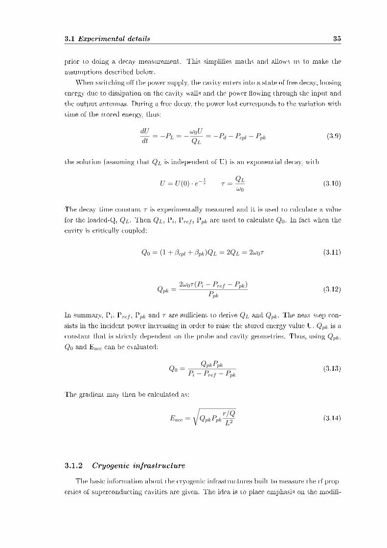
When switching o the power supply, the cavity enters into a state of free decay, loosingenergy due to dissipation on the cavity walls and the power owing through the input andthe output antennas. During a free decay, the power lost corresponds to the variation withtime of the stored energy, thus:
dU
dt= −PL = −ω0U
QL= −Pd − Pcpl − Ppk (3.9)
the solution (assuming that QL is independent of U) is an exponential decay, with
U = U(0) · e− tτ τ =
QL
ω0(3.10)
The decay time constant τ is experimentally measured and it is used to calculate a valuefor the loaded-Q, QL. Then QL, Pi, Pref , Ppk are used to calculate Q0. In fact when thecavity is critically coupled:
Q0 = (1 + βcpl + βpk)QL = 2QL = 2ω0τ (3.11)
Qpk =2ω0τ(Pi − Pref − Ppk)
Ppk(3.12)
In summary, Pi, Pref , Ppk and τ are sucient to derive QL and Qpk. The next step con-sists in the incident power increasing in order to raise the stored energy value U. Qpk is aconstant that is strictly dependent on the probe and cavity geometries. Thus, using Qpk,Q0 and Eacc can be evaluated:
Q0 =QpkPpk
Pi − Pref − Ppk(3.13)
The gradient may then be calculated as:
Eacc =
√QpkPpk
r/Q
L2(3.14)
3.1.2 Cryogenic infrastructure
The basic information about the cryogenic infrastructures built to measure the rf prop-erties of superconducting cavities are given. The idea is to place emphasis on the modi-
36Radio-frequency atmospheric plasma cleaning applied to niobium resonant
cavities
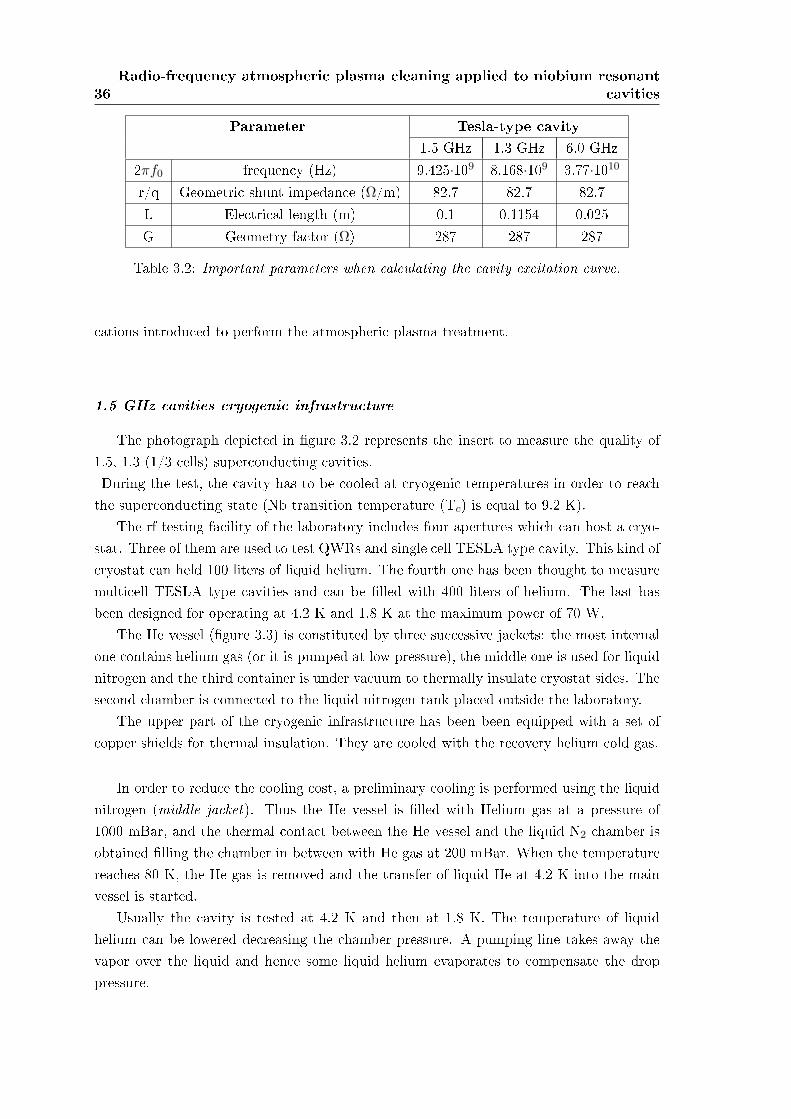
Parameter Tesla-type cavity1.5 GHz 1.3 GHz 6.0 GHz
2πf0 frequency (Hz) 9.425·109 8.168·109 3.77·1010
r/q Geometric shunt impedance (Ω/m) 82.7 82.7 82.7L Electrical length (m) 0.1 0.1154 0.025G Geometry factor (Ω) 287 287 287
Table 3.2: Important parameters when calculating the cavity excitation curve.
cations introduced to perform the atmospheric plasma treatment.
1.5 GHz cavities cryogenic infrastructure
The photograph depicted in gure 3.2 represents the insert to measure the quality of1.5, 1.3 (1/3 cells) superconducting cavities.During the test, the cavity has to be cooled at cryogenic temperatures in order to reachthe superconducting state (Nb transition temperature (Tc) is equal to 9.2 K).
The rf testing facility of the laboratory includes four apertures which can host a cryo-stat. Three of them are used to test QWRs and single cell TESLA type cavity. This kind ofcryostat can held 100 liters of liquid helium. The fourth one has been thought to measuremulticell TESLA type cavities and can be lled with 400 liters of helium. The last hasbeen designed for operating at 4.2 K and 1.8 K at the maximum power of 70 W.
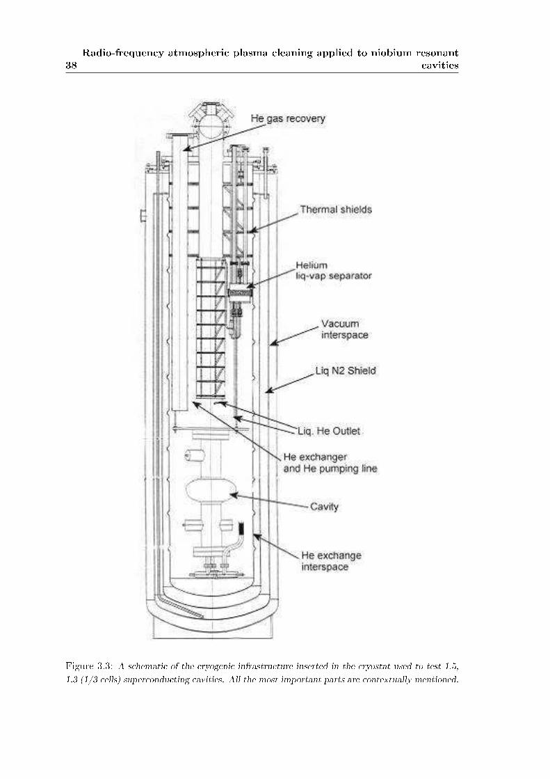
The He vessel (gure 3.3) is constituted by three successive jackets: the most internalone contains helium gas (or it is pumped at low pressure), the middle one is used for liquidnitrogen and the third container is under vacuum to thermally insulate cryostat sides. Thesecond chamber is connected to the liquid nitrogen tank placed outside the laboratory.
The upper part of the cryogenic infrastructure has been been equipped with a set ofcopper shields for thermal insulation. They are cooled with the recovery helium cold gas.
In order to reduce the cooling cost, a preliminary cooling is performed using the liquidnitrogen (middle jacket). Thus the He vessel is lled with Helium gas at a pressure of1000 mBar, and the thermal contact between the He vessel and the liquid N2 chamber isobtained lling the chamber in between with He gas at 200 mBar. When the temperaturereaches 80 K, the He gas is removed and the transfer of liquid He at 4.2 K into the mainvessel is started.
Usually the cavity is tested at 4.2 K and then at 1.8 K. The temperature of liquidhelium can be lowered decreasing the chamber pressure. A pumping line takes away thevapor over the liquid and hence some liquid helium evaporates to compensate the droppressure.
3.1 Experimental details 37
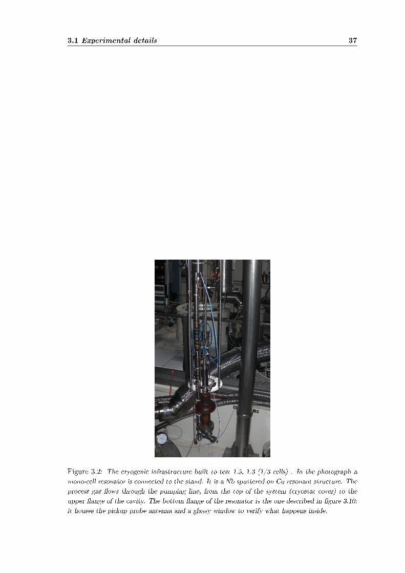
Figure 3.2: The cryogenic infrastructure built to test 1.5, 1.3 (1/3 cells) . In the photograph amono-cell resonator is connected to the stand. It is a Nb sputtered on Cu resonant structure. Theprocess gas ows through the pumping line, from the top of the system (cryostat cover) to theupper ange of the cavity. The bottom ange of the resonator is the one described in gure 3.10:it houses the pickup probe antenna and a glassy window to verify what happens inside.
38Radio-frequency atmospheric plasma cleaning applied to niobium resonant
cavities
Figure 3.3: A schematic of the cryogenic infrastructure inserted in the cryostat used to test 1.5,1.3 (1/3 cells) superconducting cavities. All the most important parts are contextually mentioned.
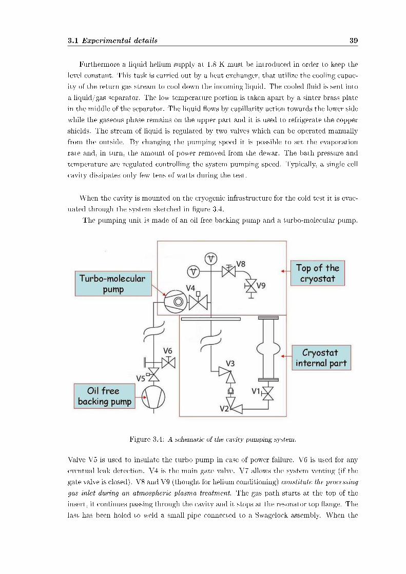
3.1 Experimental details 39
Furthermore a liquid helium supply at 1.8 K must be introduced in order to keep thelevel constant. This task is carried out by a heat exchanger, that utilize the cooling capac-ity of the return gas stream to cool down the incoming liquid. The cooled uid is sent intoa liquid/gas separator. The low temperature portion is taken apart by a sinter brass platein the middle of the separator. The liquid ows by capillarity action towards the lower sidewhile the gaseous phase remains on the upper part and it is used to refrigerate the coppershields. The stream of liquid is regulated by two valves which can be operated manuallyfrom the outside. By changing the pumping speed it is possible to set the evaporationrate and, in turn, the amount of power removed from the dewar. The bath pressure andtemperature are regulated controlling the system pumping speed. Typically, a single cellcavity dissipates only few tens of watts during the test.
When the cavity is mounted on the cryogenic infrastructure for the cold test it is evac-uated through the system sketched in gure 3.4.
The pumping unit is made of an oil free backing pump and a turbo-molecular pump.
Figure 3.4: A schematic of the cavity pumping system.
Valve V5 is used to insulate the turbo pump in case of power failure. V6 is used for anyeventual leak detection. V4 is the main gate valve. V7 allows the system venting (if thegate valve is closed). V8 and V9 (thought for helium conditioning) constitute the processinggas inlet during an atmospheric plasma treatment. The gas path starts at the top of theinsert, it continues passing through the cavity and it stops at the resonator top ange. Thelast has been holed to weld a small pipe connected to a Swagelock assembly. When the
40Radio-frequency atmospheric plasma cleaning applied to niobium resonant
cavities
process gas is helium it has to be properly recovered (through the Lab automatic recoverysystem).
V3 allows leaving under vacuum the "xed" part of the system, which is connected tothe cavity by the VCR between V2 and V3.
The cryostat vacuum chamber has a long pipe connecting the pumps (at room temper-ature) to the cavity immersed in the liquid helium. In this situation the cavity itself actsas a cryogenic pump, while the low conductance of the pipe reduces the eective pumpingspeed of the upper pumps. It is thus advisable to evacuate the cavity before the mountingon the cryostat insert using a separated vacuum facility.
Finally, after an overnight baking and 8 hours of pumping the pressure is usually inthe 10−9 mbar range.
6 GHz cavities cryogenic infrastructure
The stand we use to perform the rf tests of 6 GHz cavities has been recently built [27]and its global appearance is depicted in gure 3.5.
This insert is very compact: it has been conceived to enter a 450 or 250 l dewar neck.Such an infrastructure permit us to signicantly reduce the cryogenic power consump-
tion, avoiding any loss during a helium transfer into a cryostat: a measurement performedat 4.2 K requires roughly 30 liters of liquid He.
On the 6 GHz stand top ange a few holes have been properly drilled to allow a waythrough for the two rf cables, the thermal probe and the vacuum line (gure 3.6).The most important thing to notice is the all metal valve placed to permit the process gasto ow in when necessary. All the technical details are deeply analyzed in [27]: I just wantto underline the gas path starts at the top of the insert, it continues passing through thecavity and than it goes back to the stand upper part to be recovered.
There is a linear feedthrough (gure 3.6) that, together with the bellow connected onthe upper cavity ange, permits the coupler antenna motion. It is surrounded by a metalstructure used to x the stand to the overhead traveling crane during the needed displace-ments. The rf cables connectors (N-type) are clearly visible too: they are embedded intotwo supports, thought to avoid their stresses or motions during the cavity measurement.
As shown in gure 3.7, to oversimplify the system assembling, the bottom part ofit has been made completely independent: the small cavity can be mounted without thepresence of the complete stand that would make the work complicated. The cavity isclosed by two stainless steel anges, on which the rf SMA connectors are welded. A 1.5mm diameter indium wire is squeezed between these anges and the cavity at borderswith eight stainless steel half round rings.
Four teon coated vertical bar lines preserve the system alignment and prevent block-age problems due to the freeze-over of the bellow upper ange during the liquid heliuminsertion step.
The bottom part is covered by a µ-metal shield during the rf tests.

3.1 Experimental details 41
Figure 3.5: The cryogenic infrastructure built to test 6 GHz superconductive cavities. In thephotograph a bulk niobium resonator is connected to the stand. The process gas ows (throughthe pumping line) from the top of the system to the small resonator, then it runs up again tobe recovered. As a comparison look at the stand used for 1.5/1.3 GHz (on the left side of thephotograph) to notice their dierent dimensions. The small 6 GHz testing apparatus has beendesigned to enter a 250/450 liters liquid helium dewar.
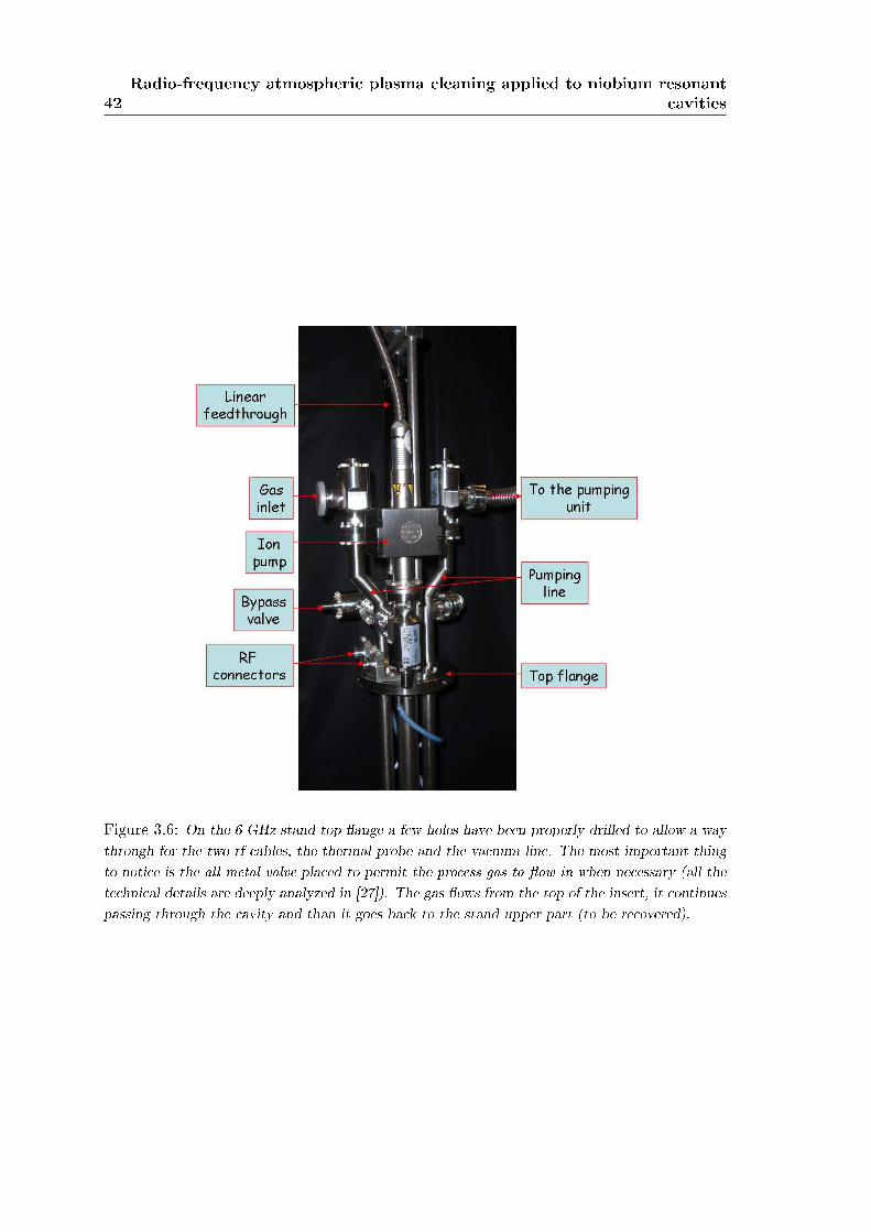
42Radio-frequency atmospheric plasma cleaning applied to niobium resonant
cavities
Figure 3.6: On the 6 GHz stand top ange a few holes have been properly drilled to allow a waythrough for the two rf cables, the thermal probe and the vacuum line. The most important thingto notice is the all metal valve placed to permit the process gas to ow in when necessary (all thetechnical details are deeply analyzed in [27]). The gas ows from the top of the insert, it continuespassing through the cavity and than it goes back to the stand upper part (to be recovered).
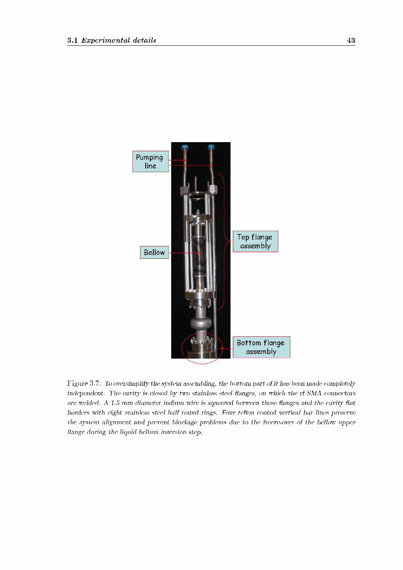
3.1 Experimental details 43
Figure 3.7: To oversimplify the system assembling, the bottom part of it has been made completelyindependent. The cavity is closed by two stainless steel anges, on which the rf SMA connectorsare welded. A 1.5 mm diameter indium wire is squeezed between these anges and the cavity atborders with eight stainless steel half round rings. Four teon coated vertical bar lines preservethe system alignment and prevent blockage problems due to the freeze-over of the bellow upperange during the liquid helium insertion step.
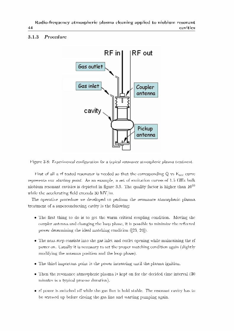
44Radio-frequency atmospheric plasma cleaning applied to niobium resonant
cavities
3.1.3 Procedure
Figure 3.8: Experimental conguration for a typical resonance atmospheric plasma treatment.
First of all a rf tested resonator is needed so that the corresponding Q vs Eacc curverepresents our starting point. As an example, a set of excitation curves of 1.5 GHz bulkniobium resonant cavities is depicted in gure 3.9. The quality factor is higher than 1010
while the accelerating eld exceeds 30 MV/m.The operative procedure we developed to perform the resonance atmospheric plasma
treatment of a superconducting cavity is the following:
• The rst thing to do is to get the warm critical coupling condition. Moving thecoupler antenna and changing the loop phase, it is possible to minimize the reectedpower determining the ideal matching condition ([23, 24]).
• The next step consists into the gas inlet and outlet opening while maintaining the rfpower on. Usually it is necessary to set the proper matching condition again (slightlymodifying the antenna position and the loop phase).
• The third important point is the power increasing until the plasma ignition.
• Then the resonance atmospheric plasma is kept on for the decided time interval (30minutes is a typical process duration).
• rf power is switched o while the gas ux is hold stable. The resonant cavity has tobe screwed up before closing the gas line and starting pumping again.
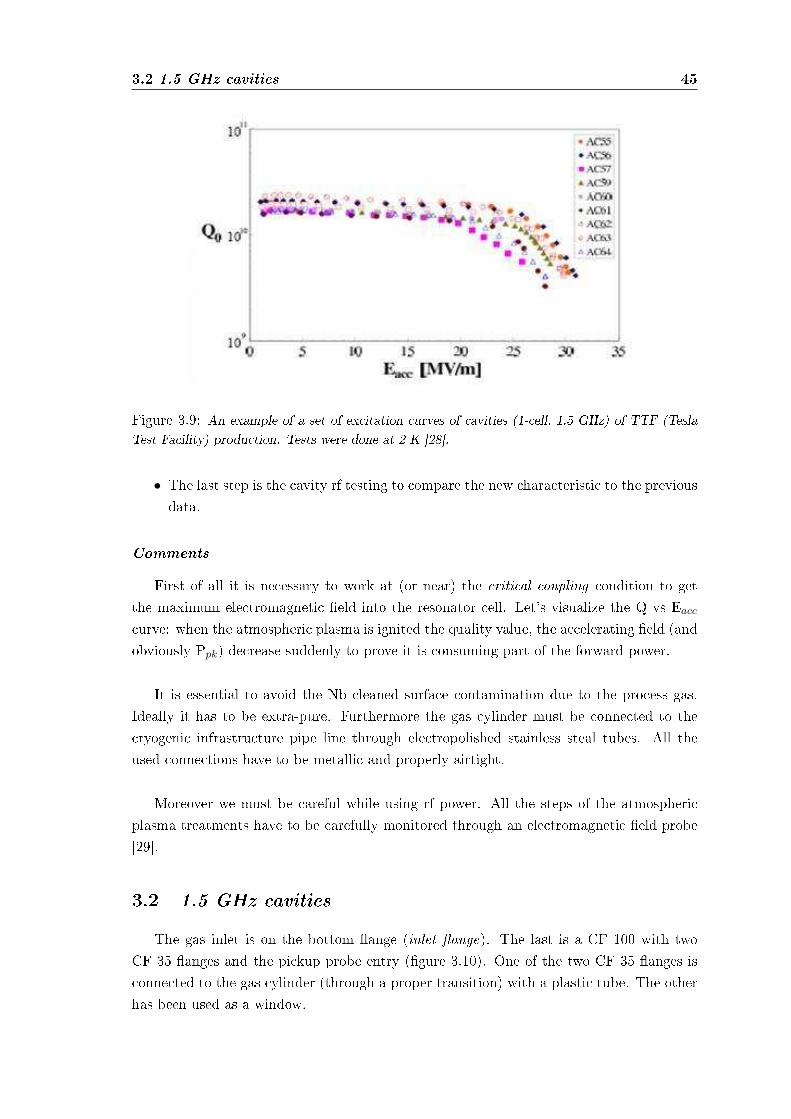
3.2 1.5 GHz cavities 45
Figure 3.9: An example of a set of excitation curves of cavities (1-cell, 1.5 GHz) of TTF (TeslaTest Facility) production. Tests were done at 2 K [28].
• The last step is the cavity rf testing to compare the new characteristic to the previousdata.
Comments
First of all it is necessary to work at (or near) the critical coupling condition to getthe maximum electromagnetic eld into the resonator cell. Let's visualize the Q vs Eacc
curve: when the atmospheric plasma is ignited the quality value, the accelerating eld (andobviously Ppk) decrease suddenly to prove it is consuming part of the forward power.
It is essential to avoid the Nb cleaned surface contamination due to the process gas.Ideally it has to be extra-pure. Furthermore the gas cylinder must be connected to thecryogenic infrastructure pipe line through electropolished stainless steal tubes. All theused connections have to be metallic and properly airtight.
Moreover we must be careful while using rf power. All the steps of the atmosphericplasma treatments have to be carefully monitored through an electromagnetic eld probe[29].
3.2 1.5 GHz cavities
The gas inlet is on the bottom ange (inlet ange). The last is a CF 100 with twoCF 35 anges and the pickup probe entry (gure 3.10). One of the two CF 35 anges isconnected to the gas cylinder (through a proper transition) with a plastic tube. The otherhas been used as a window.
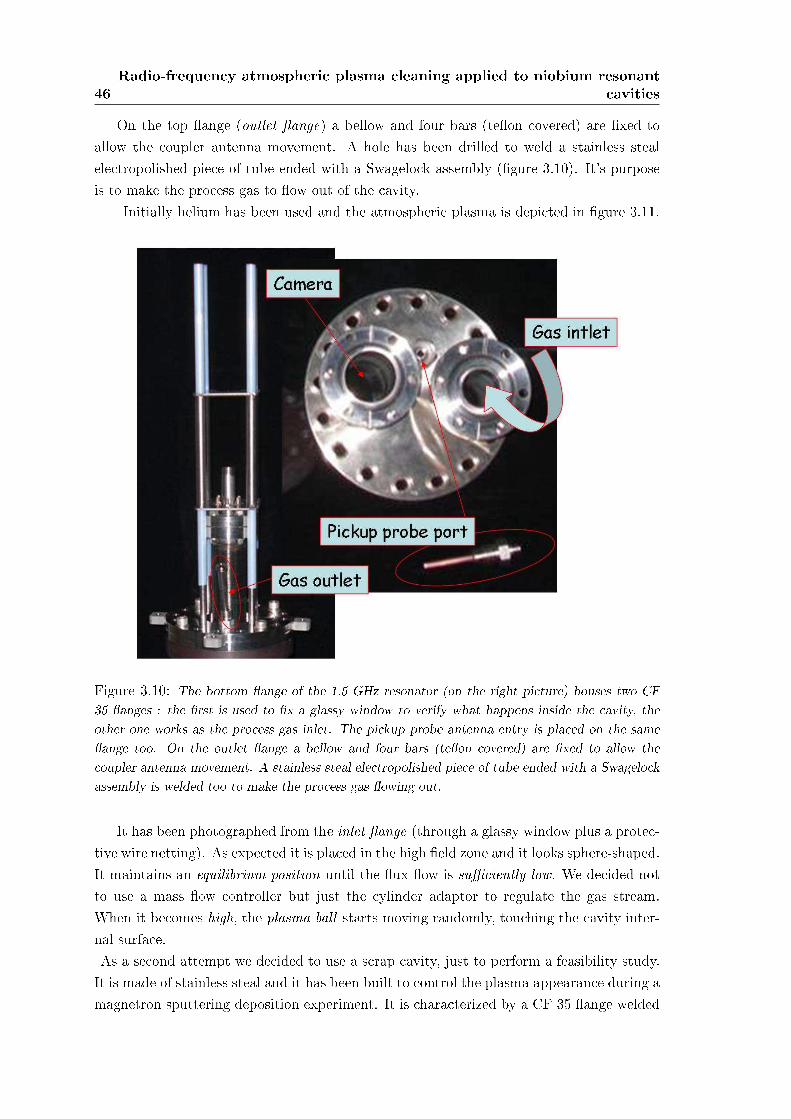
46Radio-frequency atmospheric plasma cleaning applied to niobium resonant
cavities
On the top ange (outlet ange) a bellow and four bars (teon covered) are xed toallow the coupler antenna movement. A hole has been drilled to weld a stainless stealelectropolished piece of tube ended with a Swagelock assembly (gure 3.10). It's purposeis to make the process gas to ow out of the cavity.
Initially helium has been used and the atmospheric plasma is depicted in gure 3.11.
Figure 3.10: The bottom ange of the 1.5 GHz resonator (on the right picture) houses two CF35 anges : the rst is used to x a glassy window to verify what happens inside the cavity, theother one works as the process gas inlet. The pickup probe antenna entry is placed on the sameange too. On the outlet ange a bellow and four bars (teon covered) are xed to allow thecoupler antenna movement. A stainless steal electropolished piece of tube ended with a Swagelockassembly is welded too to make the process gas owing out.
It has been photographed from the inlet ange (through a glassy window plus a protec-tive wire netting). As expected it is placed in the high eld zone and it looks sphere-shaped.It maintains an equilibrium position until the ux ow is suciently low. We decided notto use a mass ow controller but just the cylinder adaptor to regulate the gas stream.When it becomes high, the plasma ball starts moving randomly, touching the cavity inter-nal surface.As a second attempt we decided to use a scrap cavity, just to perform a feasibility study.It is made of stainless steal and it has been built to control the plasma appearance during amagnetron sputtering deposition experiment. It is characterized by a CF 35 ange welded
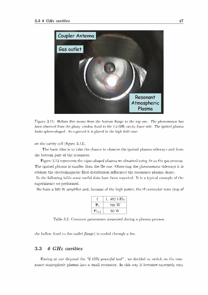
3.3 6 GHz cavities 47
Figure 3.11: Helium ux moves from the bottom ange to the top one. The phenomenon hasbeen observed from the glassy window xed to the 1.5 GHz cavity lower side. The ignited plasmalooks sphere-shaped. As expected it is placed in the high eld zone.
on the cavity cell (gure 3.12).The basic idea is to take the chance to observe the ignited plasma sideways and from
the bottom part of the resonator.Figure 3.13 represents the cigar-shaped plasma we obtained using Ar as the gas process.
The ignited plasma is smaller than the He one. Observing the phenomenon sideways it isevident the electromagnetic led distribution inuences the resonance plasma shape.In the following table some useful data have been reported. It is a typical example of theexperiments we performed.We have a 500 W amplier and, because of the high power, the rf connector zone (top of
f 1. 492 GHzPi 190 WPref 80 W
Table 3.3: Common parameters measured during a plasma process.
the bellow xed to the outlet ange) is cooled through a fen.
3.3 6 GHz cavities
Having at our disposal the "6 GHz powerful tool" , we decided to switch on the reso-nance atmospheric plasma into a small resonator. In this way it becomes extremely easy
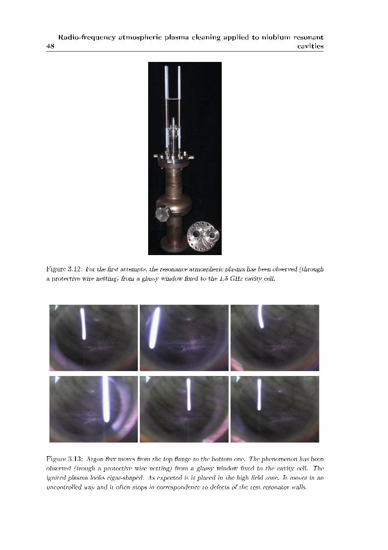
48Radio-frequency atmospheric plasma cleaning applied to niobium resonant
cavities
Figure 3.12: For the rst attempts, the resonance atmospheric plasma has been observed (througha protective wire netting) from a glassy window xed to the 1.5 GHz cavity cell.
Figure 3.13: Argon ux moves from the top ange to the bottom one. The phenomenon has beenobserved (trough a protective wire netting) from a glassy window xed to the cavity cell. Theignited plasma looks cigar-shaped. As expected it is placed in the high eld zone. It moves in anuncontrolled way and it often stops in correspondence to defects of the test resonator walls.
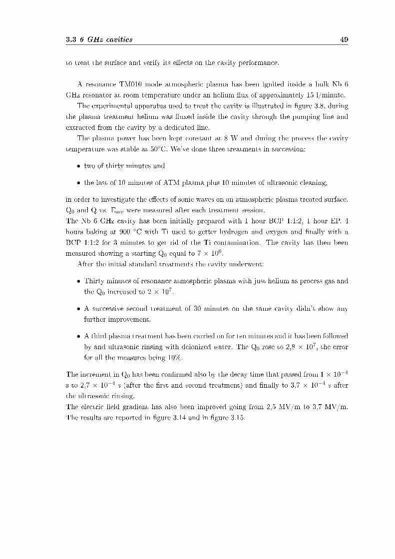
3.3 6 GHz cavities 49
to treat the surface and verify its eects on the cavity performance.
A resonance TM010 mode atmospheric plasma has been ignited inside a bulk Nb 6GHz resonator at room temperature under an helium ux of approximately 15 l/minute.
The experimental apparatus used to treat the cavity is illustrated in gure 3.8, duringthe plasma treatment helium was uxed inside the cavity through the pumping line andextracted from the cavity by a dedicated line.
The plasma power has been kept constant at 8 W and during the process the cavitytemperature was stable at 50C. We've done three treatments in succession:
• two of thirty minutes and
• the last of 10 minutes of ATM plasma plus 10 minutes of ultrasonic cleaning,
in order to investigate the eects of sonic waves on an atmospheric plasma treated surface.Q0 and Q vs. Eacc were measured after each treatment session.The Nb 6 GHz cavity has been initially prepared with 1 hour BCP 1:1:2, 1 hour EP, 4hours baking at 900 C with Ti used to getter hydrogen and oxygen and nally with aBCP 1:1:2 for 3 minutes to get rid of the Ti contamination. The cavity has then beenmeasured showing a starting Q0 equal to 7 × 10⁶.
After the initial standard treatments the cavity underwent:
• Thirty minutes of resonance atmospheric plasma with just helium as process gas andthe Q0 increased to 2 × 10⁷.
• A successive second treatment of 30 minutes on the same cavity didn't show anyfurther improvement.
• A third plasma treatment has been carried on for ten minutes and it has been followedby and ultrasonic rinsing with deionized water. The Q0 rose to 2,8 × 10⁷, the errorfor all the measures being 10%.
The increment in Q0 has been conrmed also by the decay time that passed from 1 × 10⁻⁴
s to 2,7 × 10⁻⁴ s (after the rst and second treatment) and nally to 3,7 × 10⁻⁴ s afterthe ultrasonic rinsing.The electric eld gradient has also been improved going from 2,5 MV/m to 3,7 MV/m.The results are reported in gure 3.14 and in gure 3.15.

50Radio-frequency atmospheric plasma cleaning applied to niobium resonant
cavities
Figure 3.14: Q vs. Eacc of the Nb 6 GHz cavity treated with atmospheric resonance plasma. ""starting situation; "×" 30 minutes plasma treatment; "4" 60 minutes plasma treatment.
Figure 3.15: Q0 increment after the third treatment. "×" 30 minutes plasma treatment; "♦" 10minutes plasma plus 10 minutes ultrasonic rinsing.

51
Chapter 4
Discussion
Atmospheric-pressure plasma treatment is an emerging, very versatile and inexpensivetechnique used in a variety of surface processes such as dry etching, surface treatments andmodication of surface wettability.
We have applied a resonance atmospheric plasma cleaning step to further clean a 6GHz Nb seamless cavity observing an increment in the Q0 from 7 × 10⁶ to 2 × 10⁷.
We have started the investigation of a simple, reliable and easy to set up atmosphericplasma treatment. Looking at the experimental results the most probable explanation isthat helium plasma changes the energy of the cavity internal surface. After the treatmentit becomes extremely hydrophilic.
The changing of a surface hydrophilicity/hydrophobicity (and hence water wettability)is a mechanism widely studied in the nanotechnology eld and in material science: plasmatreatment is one of the most versatile techniques used for such surface modication. It isalso widely used to alter the surface properties of materials in a number of applicationslike improving adhesion of coatings to metals and polymers [30], increasing wettability andprintability of polymers [31, 32], enhancing biocompatibility of implants [33], and in themanufacturing of semiconductor devices [34, 35].
The increased wettability due to the plasma action on the inner cavity surface hasproved to enhance the benecial action of water rinsing pushing the Q0 value further upclose to 3 × 10⁷.
Water wettabilityThe individuation and construction of the right plasma source by which it would have beenpossible and easy to treat the internal part of an accelerating cavity has been studied a bitin this Lab and the sources, characterized by a dierent plasma power, ignition mechanismand plasma shape, have been already described in [36].
The eect of a 5 minutes treatment on dierent substrates has been analyzed usingthe sessile drop method and measuring the contact angle (C.A.) of a 300 µl deionizedwater droplet. An increment in hydrophilicity and wettability has been evidenced by the

52 Discussion
decrement in the contact angle, phenomenon that has been observed for all the analyzedsubstrates.
The C.A. modications were similar with all the atmospheric plasma sources that havebeen studied and all of them presented a very similar optical emission spectrum. Therewere signals of helium, the carrier gas, and of oxygen and nitrogen present as contami-nants. The increment in water wettability (hydrophilicity) could be due to the oxidationof carbon contaminants on the surface by the chemical activated hydrossile anion OH−and radical oxygen O• but also to the creation of polar sites by the charged species formedin the plasma. Another explanation, related to the former one, is that the surface energyincreased after the plasma treatment and the formation of a solid-liquid contact area wasenergetically favorite if compared to the solid-gas one. The changing in surface energycould also be responsible for a dierent interaction between the solid and the adsorbedgases that could desorb leaving a cleaner surface.
Resonance plasmaThe shape of the plasma inside the cavity is determined by the electric and magnetic eld
Figure 4.1: Magnetic and electric eld distribution of the fundamental mode TM010 referred toa tesla type cavity.
of the excited fundamental mode. The electric eld module is the highest in the center ofthe cell while the magnetic eld has its highest module in the border region of the cell, as

53
reported in gure 4.1.With this electric and magnetic eld distribution, the plasma assume a cigar shape: it
is centered in the cavity cell (with its main axis parallel to the resonator one) and has thecapacity to uniformly treat its internal surface.
Surfactants analogySurfactants that are present in soaps have the property to increase the surface wettabilityby shielding the water intermolecular interactions and hence decreasing the surface ten-sion. Therefore water with surfactants can spread better on the surface that has to becleaned. The cleaning action can be more eective also in the small interstitial volumeswhich would not be treated by a liquid with low wettability and high surface tension. Sohigh wettability means high interaction between the solid and the liquid. This high inter-action can be achieved by using atmospheric plasma too. The main advantage is it doesn'tleave contaminants on the surface as it happens with soaps.In our experiment the cleaning process has been enhanced by the ultrasonic rinse whoseaction has been made more eective by the high wettability of the cavity internal surface.

54 Discussion
55
Chapter 5
Conclusions and future plan
More experiments will be carried on 6 GHz cavities exploring the eects of rinsing timeand helium ux variation.
The cleaning process will be also studied on 1.5/1.3 GHz cavities in order to analyzewhat happens when the ratio ionization volume/cell surface decreases. It is easy to thinkthe plasma ball has to be maintained close enough to the surface to be treated: as alreadydiscussed, it moves randomly when the ux ow is high. It is mandatory to understandeverything about the gas stream dynamic and to make the plasma to touch the resonatorinternal surface.
Moreover it could be interesting to try to ignite a resonance atmospheric plasma intoa multi-cell cavity.
The chemical activation by atmospheric plasma gives also the possibility to add reactivegases in the carrier ux and investigate the etching rate due to chemical activated uorineions coming from mixture of CF4, NF3 with and without oxygen. These gas mixtures havealready successfully been used to etch Nb in the semiconductor industry for the realizationof Josephson junctions ([37, 38]).
The following step will consist in the realization of dierent atmospheric congurationsas corona plasma, plasma jet and torch.

56 Conclusions and future plan
57
Appendix A
Basics of superconductingradio-frequency cavities
In this chapter we give an overview of the basics of superconducting cavities. We startby discussing the electrodynamics of radiofrequency (rf) cavities, the accelerating modeand the general expressions used to describe power dissipation. Although later we focusexclusively on superconducting cavities, this section apply equally well to both normal andsuperconducting resonant structures.
In the second part we introduce the rudiments of superconductivity. In particular, wewill illustrate why superconducting cavities dissipate a small, but nite amount of powerdespite the fact that superconductors carry dc currents without losses. We will also explainthe fundamental magnetic eld limitation of superconducting cavities.
This chapter is not designed to give a deep description of the theory of cavities: we willjust emphasize the aspects needed to understand this report. For further information thereader is referred to numerous texts that give an excellent review of the subject (see, forexample [1, 39]).
A.1 Cavity fundamentals and cavity elds
A.1.1 Radio-frequency elds in cavities
The rf eld in cavities are derived from the eigenvalue equation(∇2 − 1
c2
∂2
∂t2
)(E
H
)= 0 (A.1)
which is obtained by combining Maxwell's equations [40]. It is subject to the boundaryconditions
n×E = 0 (A.2)
andn ·H = 0 (A.3)
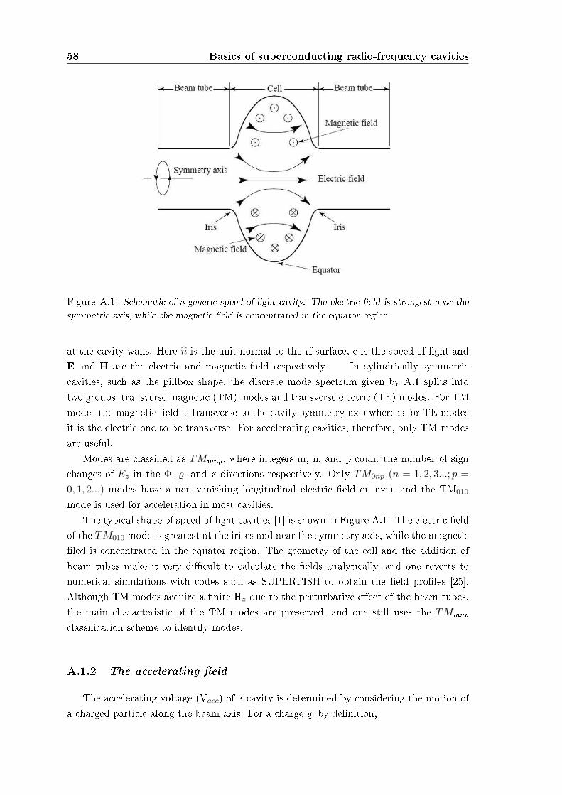
58 Basics of superconducting radio-frequency cavities
Figure A.1: Schematic of a generic speed-of-light cavity. The electric eld is strongest near thesymmetric axis, while the magnetic eld is concentrated in the equator region.
at the cavity walls. Here n is the unit normal to the rf surface, c is the speed of light andE and H are the electric and magnetic eld respectively. In cylindrically symmetriccavities, such as the pillbox shape, the discrete mode spectrum given by A.1 splits intotwo groups, transverse magnetic (TM) modes and transverse electric (TE) modes. For TMmodes the magnetic eld is transverse to the cavity symmetry axis whereas for TE modesit is the electric one to be transverse. For accelerating cavities, therefore, only TM modesare useful.
Modes are classied as TMmnp, where integers m, n, and p count the number of signchanges of Ez in the Φ, %, and z directions respectively. Only TM0np (n = 1, 2, 3...; p =0, 1, 2...) modes have a non vanishing longitudinal electric eld on axis, and the TM010
mode is used for acceleration in most cavities.The typical shape of speed of light cavities [1] is shown in Figure A.1. The electric eld
of the TM010 mode is greatest at the irises and near the symmetry axis, while the magneticled is concentrated in the equator region. The geometry of the cell and the addition ofbeam tubes make it very dicult to calculate the elds analytically, and one reverts tonumerical simulations with codes such as SUPERFISH to obtain the eld proles [25].Although TM modes acquire a nite Hz due to the perturbative eect of the beam tubes,the main characteristic of the TM modes are preserved, and one still uses the TMmnpclassication scheme to identify modes.
A.1.2 The accelerating eld
The accelerating voltage (Vacc) of a cavity is determined by considering the motion ofa charged particle along the beam axis. For a charge q, by denition,
A.1 Cavity fundamentals and cavity elds 59
Vacc =
∣∣∣∣∣1q×max energy gain possible during transit
∣∣∣∣∣ (A.4)
We use 6 GHz speed of light structures in our tests, and the accelerating voltage is there-fore given by
Vacc =
∣∣∣∣∣∫ z=d
z=0Ez(ρ = 0, z)e
iω0zc dz
∣∣∣∣∣ (A.5)
where d is the length of the cavity and and ω0 is the eigenfrequency of the cavity modeunder consideration. Frequently, one quotes the accelerating eld Eacc rather than Vacc.The two are related by
Eacc =Vacc
d(A.6)
With single cell cavities the choice of d is somewhat ambiguous, since the beam tubes canbe made arbitrarily long. Hence Eacc is not uniquely dened. Frequently one thereforecalculates Eacc for an equivalent innite periodic structure and quotes its Eacc for the singlecell.
A.1.3 Peak surface elds
When considering the practical limitations of superconducting cavities, two elds areof particular importance: the peak electric surface eld (Epk) and the peak magnetic sur-face eld (Hpk). In most cases these elds determine the maximum achievable acceleratinggradient in cavities. In the ones we have (6 GHz speed of light structures), the surfaceelectric eld peaks near the irises, and the surface magnetic eld is at its maximum nearthe equator. To maximize the potential cavity performance, it is important that the ratiosof Epk/Eacc and Hpk/Eacc be minimized.
In an ideal pillbox cavity, the ratios are given by
Epk
Eacc=
π
2= 1.6 (A.7)
Hpk
Eacc= 30.5
Oe
MV/m(A.8)
The addition of beam tubes increases these values. For example, the ratios of monocellTESLA-type cavities are
Epk
Eacc= 1.83 (A.9)
Hpk
Eacc= 45
Oe
MV/m(A.10)
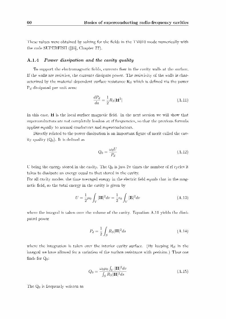
60 Basics of superconducting radio-frequency cavities
These values were obtained by solving for the elds in the TM010 mode numerically withthe code SUPERFISH ([25], Chapter ??).
A.1.4 Power dissipation and the cavity quality
To support the electromagnetic elds, currents ow in the cavity walls at the surface.If the walls are resistive, the currents dissipate power. The resistivity of the walls is char-acterized by the material dependent surface resistance RS which is dened via the powerPd dissipated per unit area:
dPd
da=
12RS |H2| (A.11)
In this case, H is the local surface magnetic eld. In the next section we will show thatsuperconductors are not completely lossless at rf frequencies, so that the previous formulaapplies equally to normal conductors and superconductors.
Directly related to the power dissipation is an important gure of merit called the cav-ity quality (Q0). It is dened as
Q0 =ω0U
Pd(A.12)
U being the energy stored in the cavity. The Q0 is just 2π times the number of rf cycles ittakes to dissipate an energy equal to that stored in the cavity.For all cavity modes, the time averaged energy in the electric eld equals that in the mag-netic eld, so the total energy in the cavity is given by
U =12µ0
∫
V|H|2dv =
12ε0
∫
V|E|2dv (A.13)
where the integral is taken over the volume of the cavity. Equation A.11 yields the dissi-pated power
Pd =12
∫
SRS |H|2ds (A.14)
where the integration is taken over the interior cavity surface. (By keeping RS in theintegral we have allowed for a variation of the surface resistance with position.) Thus onends for Q0:
Q0 =ω0µ0
∫V |H|2dv∫
S RS |H|2ds(A.15)
The Q0 is frequently written as
A.1 Cavity fundamentals and cavity elds 61
Q0 =G
RS
(A.16)
where
G =ω0µ0
∫V |H|2dv∫
S |H|2ds(A.17)
is known as the geometry constant, and
RS =
∫S RS |H|2ds∫
S |H|2ds(A.18)
is the mean surface resistance (weighted by H2). For the 6 GHz cavities we studied G =287 Ω.

62 Basics of superconducting radio-frequency cavities

LIST OF TABLES 63
List of Tables
3.1 RF variables . . . . . . . . . . . . . . . . . . . . . . . . . . . . . . . . . . . . 323.2 Cavity rf parameters . . . . . . . . . . . . . . . . . . . . . . . . . . . . . . . 363.3 RF variables . . . . . . . . . . . . . . . . . . . . . . . . . . . . . . . . . . . . 47

64 LIST OF TABLES
LIST OF FIGURES 65
List of Figures
1.1 A seamless Tesla Type bulk niobium 6 GHz cavity. Spun resonators don't needwelding (even for anges). . . . . . . . . . . . . . . . . . . . . . . . . . . . . . 2
1.2 Spinning of a seamless multicell resonator from a circular blank. . . . . . . . . . . 2
2.1 Evolution of the plasma temperature (electrons and heavy particles) with the pres-sure in a mercury plasma arc. . . . . . . . . . . . . . . . . . . . . . . . . . . . 11
2.2 Principle of a Corona discharge and a hollow needle to plate discharge (left: positiveneedle, right: negative needle). . . . . . . . . . . . . . . . . . . . . . . . . . . . 13
2.3 Principle of dielectric barrier discharge (picture: a non equilibrium diuse plasmaat atmospheric pressure. . . . . . . . . . . . . . . . . . . . . . . . . . . . . . . 14
2.4 Principle of arc plasma torches (left: current-carrying arc; right: transferred arc). . 15
2.5 RF plasma torch. . . . . . . . . . . . . . . . . . . . . . . . . . . . . . . . . . . 15
2.6 Left: cold plasma torch design. Right: barrier torch design. . . . . . . . . . . . . 16
2.7 APPJ design. . . . . . . . . . . . . . . . . . . . . . . . . . . . . . . . . . . . . 17
2.8 A schematic diagram of continuous corona discharge system for wool and mohair. . 18
2.9 A schematic diagram of continuous corona system for Polypropylene Fiber Towdesigned by Sherman Treaters [8]. . . . . . . . . . . . . . . . . . . . . . . . . . 19
2.10 Hydrophilic treatment of blood lters, capillarities (upper photograph): anotherand specially developed activation process can be used to make the surface hy-drophilic. This permanently hydrophilic character is used to give woven, and nonwoven textiles the capability to be used as blood lter or ltering membranes forspecic applications. Applications are micro ltration systems based on these tex-tiles or capillaries: blood lters, dialysis lter systems etc. Hydrophobic treatmentof non woven PP (bottom photograph): by using semi-continuous textile treatersit is possible to plasma polymerize the surface of non woven and other textiles sothat they become hydrophobic of nature. A lot of industrial users are looking toreplace their conventional techniques or improve the nal result by using plasmatechnology. Applications are oleophobic or hydrophobic treatment of paper, tissuesand lter elements. . . . . . . . . . . . . . . . . . . . . . . . . . . . . . . . . . 21
66 LIST OF FIGURES
2.11 To promote the Research and the Technological Transfer in the eld of PlasmaApplications, the University of Milano-Bicocca, together with the Regione Lom-bardia and the Fondazione Cariplo, supported the creation of a Centre of Excel-lence on Plasma Applications. The Centre of Excellence PLASMAPROMETEOwas established on February 12 th 2004 on the basis of an agreement between theUniversity of Milano-Bicocca and the Regione Lombardia. The aims of the Centreis to promote Technological Transfer and training to Small Medium Enterprises.(http://www.plasmaprometeo.unimib.it/history.php) . . . . . . . . . . . . . . . 25
2.12 Tantec has been oering cutting-edge and environmentally-friendly Plasma andCorona surface treatment equipment for over thirty years. Tantec develops, man-ufactures and markets innovative equipment worldwide for Plasma and Coronasurface treatment of plastic components. Atmospheric Plasma treating systemprovides an economical solution for the cleaning and activation of complex sur-faces before further processing. Component preparation is an important step priorto bonding, painting, varnishing and coating processes. . . . . . . . . . . . . . . 27
2.13 The mobile phone housing is cleaned by a rotating plasma jet prior to painting.Vehicle manufacturer has been using Openair plasma for pretreating plastic sur-faces. Switches with laser-etched symbols, high-gloss decorative strips and covers,scratch resistant displays and glittering fascias, ventilator grilles or glove compart-ments even plastic parts in the interiors of automobiles can be pretreated usingplasma. . . . . . . . . . . . . . . . . . . . . . . . . . . . . . . . . . . . . . . . 28
3.1 Input coupler arrangement used to couple rf power into the cavity. . . . . . . . . 33
3.2 The cryogenic infrastructure built to test 1.5, 1.3 (1/3 cells) . In the photograph amono-cell resonator is connected to the stand. It is a Nb sputtered on Cu resonantstructure. The process gas ows through the pumping line, from the top of thesystem (cryostat cover) to the upper ange of the cavity. The bottom ange of theresonator is the one described in gure 3.10: it houses the pickup probe antennaand a glassy window to verify what happens inside. . . . . . . . . . . . . . . . . 37
3.3 A schematic of the cryogenic infrastructure inserted in the cryostat used to test1.5, 1.3 (1/3 cells) superconducting cavities. All the most important parts arecontextually mentioned. . . . . . . . . . . . . . . . . . . . . . . . . . . . . . . 38
3.4 A schematic of the cavity pumping system. . . . . . . . . . . . . . . . . . . . . 39
3.5 The cryogenic infrastructure built to test 6 GHz superconductive cavities. In thephotograph a bulk niobium resonator is connected to the stand. The processgas ows (through the pumping line) from the top of the system to the smallresonator, then it runs up again to be recovered. As a comparison look at thestand used for 1.5/1.3 GHz (on the left side of the photograph) to notice theirdierent dimensions. The small 6 GHz testing apparatus has been designed toenter a 250/450 liters liquid helium dewar. . . . . . . . . . . . . . . . . . . . . 41
LIST OF FIGURES 67
3.6 On the 6 GHz stand top ange a few holes have been properly drilled to allow away through for the two rf cables, the thermal probe and the vacuum line. Themost important thing to notice is the all metal valve placed to permit the processgas to ow in when necessary (all the technical details are deeply analyzed in [27]).The gas ows from the top of the insert, it continues passing through the cavityand than it goes back to the stand upper part (to be recovered). . . . . . . . . . 42
3.7 To oversimplify the system assembling, the bottom part of it has been made com-pletely independent. The cavity is closed by two stainless steel anges, on whichthe rf SMA connectors are welded. A 1.5 mm diameter indium wire is squeezedbetween these anges and the cavity at borders with eight stainless steel halfround rings. Four teon coated vertical bar lines preserve the system alignmentand prevent blockage problems due to the freeze-over of the bellow upper angeduring the liquid helium insertion step. . . . . . . . . . . . . . . . . . . . . . . 43
3.8 Experimental conguration for a typical resonance atmospheric plasma treatment. 443.9 An example of a set of excitation curves of cavities (1-cell, 1.5 GHz) of TTF (Tesla
Test Facility) production. Tests were done at 2 K [28]. . . . . . . . . . . . . . . 453.10 The bottom ange of the 1.5 GHz resonator (on the right picture) houses two CF
35 anges : the rst is used to x a glassy window to verify what happens insidethe cavity, the other one works as the process gas inlet. The pickup probe antennaentry is placed on the same ange too. On the outlet ange a bellow and fourbars (teon covered) are xed to allow the coupler antenna movement. A stainlesssteal electropolished piece of tube ended with a Swagelock assembly is welded tooto make the process gas owing out. . . . . . . . . . . . . . . . . . . . . . . . . 46
3.11 Helium ux moves from the bottom ange to the top one. The phenomenon hasbeen observed from the glassy window xed to the 1.5 GHz cavity lower side. Theignited plasma looks sphere-shaped. As expected it is placed in the high eld zone. 47
3.12 For the rst attempts, the resonance atmospheric plasma has been observed (througha protective wire netting) from a glassy window xed to the 1.5 GHz cavity cell. . 48
3.13 Argon ux moves from the top ange to the bottom one. The phenomenon hasbeen observed (trough a protective wire netting) from a glassy window xed tothe cavity cell. The ignited plasma looks cigar-shaped. As expected it is placedin the high eld zone. It moves in an uncontrolled way and it often stops incorrespondence to defects of the test resonator walls. . . . . . . . . . . . . . . . 48
3.14 Q vs. Eacc of the Nb 6 GHz cavity treated with atmospheric resonance plasma."" starting situation; "×" 30 minutes plasma treatment; "4" 60 minutes plasmatreatment. . . . . . . . . . . . . . . . . . . . . . . . . . . . . . . . . . . . . . 50
3.15 Q0 increment after the third treatment. "×" 30 minutes plasma treatment; "♦"10 minutes plasma plus 10 minutes ultrasonic rinsing. . . . . . . . . . . . . . . . 50
4.1 Magnetic and electric eld distribution of the fundamental mode TM010 referredto a tesla type cavity. . . . . . . . . . . . . . . . . . . . . . . . . . . . . . . . . 52

68 LIST OF FIGURES
A.1 Schematic of a generic speed-of-light cavity. The electric eld is strongest near thesymmetric axis, while the magnetic eld is concentrated in the equator region. . . 58
BIBLIOGRAPHY 69
Bibliography
[1] H. Padamsee, J. Knoblock, H. T., RF Superconductivity for Accelerators, Wiley andSons, New York, 1998.
[2] P. Bernard, et al., Proceeedings of the 1992 European Particle Accelerator Conference,edited by E.H. Henke et al. Editors Frontiers (1992) 1269.
[3] N. Pupeter, Proceedings of the 7th Workshop on RF Superconductivity, edited by B.Bonin, Gif-sur-Yvette, France (1995) 67.
[4] K. e. a. Saito, Proceedings of the 6th workshop on RF Superconductivity, edited byR.M. Sundelin, CEBAF, Newport News (1994) 1151.
[5] J. Graber, Nucl. Instrum. Methods Phys. Res. A (1994) 572.
[6] C. e. a. Crawford, Part. Accel. 1 (1995) 49.
[7] C. Tendero, C. Tixier, P. Tristant, J. Deasmaison, P. Leprince, Spectrochimica ActaB 61 (2006) 230.
[8] Y. Hwuang, Characterization of atmospheric pressure plasma interactions with tex-tile/polymer substrates, PhD Thesis, 2003.
[9] G. Abbot, G. Robinson, Textile Research Journal 47(2) (1977) 199202.
[10] S. Meiners, J. Salge, E. Prinz, F. Forster, Surface and Coatings Technology 98 (1998)11211127.
[11] S. Kanazawa, M. Kogoma, T. Moriwaki, S. Okazaki, Journal of Physics D - AppliedPhysics 21 (1988) 838840.
[12] P. Tsai, L. Wadsworth, J. Roth, Textile Research Journal 67(5) (1997) 359369.
[13] T. Montie, K. Kelly-Wintenberg, J. Roth, IEEE Transactions on Plasma Science 28(1)(2000) 4150.
[14] C. Tendero, C. Tixier, P. Tristant, J. Deasmaison, P. Leprince, 25th IEEE-ICOPSPaper 3B03 (1998) 178.
[15] A. Bradley, J. Fales, Chemical Technology 1(4) (1971) 232237.
70 BIBLIOGRAPHY
[16] Y. Iriyama, T. Yasuda, D. Cho, H. Yasuda, Journal of Applied Polymer Science 39(1990) 249264.
[17] H. Wang, M. Rembold, J. Wang, Journal of Applied Polymer Science 49 (1993) 701710.
[18] M. McCord, Y. Hwang, L. Canup, M. Qiu, Y. Bourham, Journal of Applied PolymerScience.
[19] W. Thorsen, R. Landwehr, Textile Research Journal 40(8) (1970) 688695.
[20] D. Biro, G. Pleizier, Y. Deslandes, Journal of Applied Polymer Science 47 (1993)883894.
[21] T. Wakida, S. Tokino, S. Niu, M. Lee, H. Uchiyama, M. Kaneko, Textile ResearchJOurnal 63 (1993) 438442.
[22] P. Koulik, Plasma Chemistry and Plasma Processing 20 (2000) 159161.
[23] S. Deambrosis, 6 GHz cavities: a method to test A15 intermetallic compounds rfproperties, PhD Thesis, 2008.
[24] G. Lanza, New magnetron congurations for sputtering Nb thin lms into Cu tesla-type superconducting cavities, PhD Thesis, 2008.
[25] K. Halbach, R. Holsinger, Particle Accelerators 7 (1976) 213222.
[26] T. Powers, Proceedings of the 12th workshop on RF Superconductivity, Cornell Uni-versity, Ithaca, NY, USA 0.
[27] A. Rossi, A miniaturized 6 GHz infrastructure for cutting down the cost of RF super-conducting research, Master Thesis, 2008.
[28] L. Lilje, Experimental Investigations on Superconducting Niobium Cavities at HighestRadiofrequency Fields, PhD Thesis, 2001.
[29] I. C. on Non-ionizing Radation Protection, Health Physics 74 (1998) 494521.
[30] E. Liston, L. Martinu, M. Wertheimer, J. Adhesion Sci Technol. 7 (1993) 10911127.
[31] D. Briggs, Surface treatments for polyolens, in: Surface Analysis and Pretreatmentof Plastics and Metals, Applied Sciece Publishers, Essex, England, 1982.
[32] S. Wu, Modications of polymer surfaces: mechanism of wettability and bondabilityimprovements, in: Polymer Interface and Adhesion, Marcel Dekker, New York, 1982.
[33] P. Chu, J. Chen, L. Wang, N. Huang, Mat. Sci. Eng. 36 (2002) 143206.
BIBLIOGRAPHY 71
[34] H. Shmid, B. Kegel, W. Petasch, G. Liebel, Proceedings of Joint 24th InternationalConference Microelectronics (MIEL) and 32nd Symposium Devcs Materials SD'96,Nova Gorcia, Slovenia 0 (1996) 1735.
[35] L. Lieberman, A. Lichtenberg, Principles of Plasma Discharges and Material Pro-cesing, Wiley, New York, 1994.
[36] N. Patron, R. Baracco, L. Phillips, M. Rea, C. Roncolato, D. Tonini, P. V., Proceed-ings of the thin lms workshop "pushing the limits of RFS", Legnaro, Italy 0.
[37] M. Chen, R. Wang, J. Vac. Sci. Technol. A 1.
[38] J. Sasserath, J. Vivalda, J. Vac. Sci. Technol. A 8.
[39] H. Piel, CERN Accelerator School: Superconductivity in Particle Accelerators, In S.Turner editor, Hamburg, Germany, 1988.
[40] J. Jackson, Classical Eectrodynamics, Wiley and Sons, New York, 2nd edition, 1975.

72 BIBLIOGRAPHY


