Test and Evaluation Report Laboratory Testing of Precast Paving Notch System February 25, 2008 Prepared For Iowa Department of Transportation Office of Bridges and Structures 800 Lincoln Way Ames, IA 50010 Prepared By Bridge Engineering Center 2711 South Loop Dr. Suite 4700 Ames, IA 50010 (515) 294-8103
Transcript
Test and Evaluation Report
Laboratory Testing of Precast Paving Notch System February 25, 2008 Prepared For
Iowa Department of Transportation Office of Bridges and Structures 800 Lincoln Way
Ames, IA 50010 Prepared By Bridge Engineering Center 2711 South Loop Dr. Suite 4700 Ames, IA 50010 (515) 294-8103
ii
Table of Contents INTRODUCTION ...............................................................................................................1 LABORATORY TESTING PROGRAM............................................................................2
Phase 1 – Post-tensioned without epoxy adhesive.........................................................3 Phase 2 – Drilled and epoxy grouted anchor (One row of stainless steel rods).............5 Phase 3 – Iowa DOT’s current CIP paving notch repair system ...................................6 Phase 4 – Drilled and epoxy grouted anchor (two rows of stainless steel rods)............7
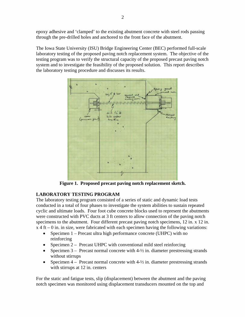
List of Figures Figure 1. Proposed precast paving notch replacement sketch ..........................................2 Figure 2. Photographs of the assembled precast paving notch system and the
application of PT force....................................................................................4 Figure 3. Load-slip test results for Phase 1.......................................................................4 Figure 4. Photographs of the application of epoxy adhesive and the assembled precast
paving notch system........................................................................................5 Figure 5. Load-slip test results for Phase 2.......................................................................6 Figure 6. Posttest specimen illustrating typical cracking failure ......................................6 Figure 7. Construction of the cast-in-place repair specimen ............................................7 Figure 8. Fatigue load test results .....................................................................................7 Figure 9. Ultimate load test on a specimen with four stainless rods.................................8 Figure 10. Posttest specimen illustrating typical cracking failure ......................................8 Figure 11. Precast paving notch system selected for field implementation......................10
1
INTRODUCTION Bridge approach pavement settlement and the resulting formation of ‘bumps’ at the end of bridges is a recurring problem on a number of Iowa bridges. One of the contributing factors in this settlement is failure of the bridge paving notch. A paving notch (also known as a corbel or a paving support) consists of a horizontal shelf constructed on the rear of a bridge abutment and is used to support the adjacent roadway pavement. Over time, these paving notches have been observed to deteriorate/fail due to a number of conditions including horizontal abutment movement due to seasonal temperature changes, loss of backfill materials by erosion, inadequate construction practices, foundation soil settlement, heavy traffic loads, salt brine that leaks through the expansion joint, and an open expansion joint that tends to fill with dirt and debris and ‘push’ the approach pavement off the paving notch. In some cases, the condition of the paving notch deterioration may not be noticed until the deterioration reaches a critical state and the approach pavement is removed. The conventional repair procedure for this problem typically consists of removing the deteriorated paving notch concrete while preserving as much of the existing reinforcing steel as possible; construction of wood forms; and placement of a cast-in-place (CIP) concrete paving notch followed by replacement of the approach slab pavement. The conventional replacement method, however, requires that the bridge be taken out of service for an extended period of time, which disrupts the traveling public. The notable number of bridges that exhibit the failing paving notch problem and, more importantly, their location on highly traveled roadways necessitate the development of a standardized, much more quickly-installed replacement method. With a standardized system, situations where the deterioration is unknown until approach pavement removal could be addressed with minimal traffic disruptions. As an alternative to the conventional paving notch construction, a precast paving notch system was proposed. The precast paving notch system was intended for use in either new construction or as rapid replacement that can be installed in single-lane-widths to allow for staged construction under traffic with a single overnight bridge closure. In close coordination with the Iowa Department of Transportation (Iowa DOT) Office of Bridges and Structures, a conceptual sketch was developed (see Figure 1), which served as the starting point for the development of the final details of a precast paving notch system. The system consists of a rectangular, precast concrete element that is connected to the rear of the abutment using high-strength threaded steel rods and an epoxy adhesive that is similar to that used in segmental bridge construction. The installation procedure of the proposed precast paving notch system would require the drilling of several small holes, approximately 1½ in. diameter, through the existing concrete abutment. These holes could be drilled from beneath the bridge prior to the closure of the roadway using a template to ensure alignment with the precast pieces. The drilled holes would be slightly larger than the steel rod to provide a slight tolerance for field variations. Following closure of the bridge, a narrow strip of approach pavement near the bridge would be removed, the deteriorated paving notch would be saw-cut and removed down to sound concrete, followed by the precast concrete element attached with
2
epoxy adhesive and ‘clamped’ to the existing abutment concrete with steel rods passing through the pre-drilled holes and anchored to the front face of the abutment. The Iowa State University (ISU) Bridge Engineering Center (BEC) performed full-scale laboratory testing of the proposed paving notch replacement system. The objective of the testing program was to verify the structural capacity of the proposed precast paving notch system and to investigate the feasibility of the proposed solution. This report describes the laboratory testing procedure and discusses its results.
LABORATORY TESTING PROGRAM The laboratory testing program consisted of a series of static and dynamic load tests conducted in a total of four phases to investigate the system abilities to sustain repeated cyclic and ultimate loads. Four foot cube concrete blocks used to represent the abutments were constructed with PVC ducts at 3 ft centers to allow connection of the paving notch specimens to the abutment. Four different precast paving notch specimens, 12 in. x 12 in. x 4 ft – 0 in. in size, were fabricated with each specimen having the following variations:
• Specimen 1 – Precast ultra high performance concrete (UHPC) with no reinforcing
• Specimen 2 – Precast UHPC with conventional mild steel reinforcing • Specimen 3 – Precast normal concrete with 4-½ in. diameter prestressing strands
without stirrups • Specimen 4 – Precast normal concrete with 4-½ in. diameter prestressing strands
with stirrups at 12 in. centers For the static and fatigue tests, slip (displacement) between the abutment and the paving notch specimen was monitored using displacement transducers mounted on the top and
3
bottom surfaces of the paving notch specimen. A computer controlled data acquisition system (DAS) was used to record all of the data gathered during testing. Following successful completion of the service level static and fatigue tests, each of the precast paving notches were loaded to failure to obtain a measure of the ultimate strength of the precast concrete components and connection details. During the testing, the research team found out that the ‘abutment’ was weaker than any of the four specimens and the test results, therefore, were not affected by the specimen material. This report presents typical results for the tested specimens. Phase 1 – Post-tensioned without epoxy adhesive The first phase of testing was intended to investigate the post-tensing (PT) force needed to prevent slip of the paving notch system (i.e., friction force between the abutment and the paving notch specimen) without using an adhesive. Assembly of the paving notch system involved attaching the paving notch specimen to the abutment block with 1 in. diameter Dywidag threaded rods – 127.5-kip ultimate strength capacity [1] – spaced at 3 ft on centers. After placement of the paving notch specimen to the abutment, the paving notch system was post-tensioned using a compact lightweight hydraulic jack containing a socket wrench and ratchet device that allows the nut to be tightened as the rod elongates. The paving notch system was instrumented with three displacement transducers: one transducer on top surface of the paving notch specimen directly above the load point and two transducers on the bottom surface of the paving notch specimen directly below the Dywidag threaded rods. Photographs of the assembled precast paving notch system instrumented with displacement transducers and the application of PT force are presented in Fig. 2. Before the first static load test started, the paving notch system was post-tensioned at 77 kips, which is equivalent to approximately 60 % of the ultimate strength of the Dywidag PT rods [1]. During testing, a single point load, using a hydraulic jack placed under the center of the paving notch specimen, was slowly applied up to 32 kips. The force was then slowly released to zero and this loading sequence was repeated three times. A total of six static load tests were conducted with each test completed in a similar manner with the exception of the PT force applied to the system; the next static load test involved the specimen with 10% less PT force applied to the system (i.e., 50% of the ultimate strength of the rods). The static load test was repeated until the PT force was down to 13 kips (i.e., approximately 10% of the ultimate strength of the rods). The load-slip measurements were made for each static load test and are presented in Fig. 3. Before testing, it was expected that, when there was adequate frictional resistance, any displacement induced by an applied load would return to zero when the load was removed. This was confirmed by the first static load testing where virtually no residual displacement (slip) occurred at the connection of the paving notch system when the specimen was attached to the abutment with 77 kips of PT force. The initial indication of slippage was observed at 26 kips of PT force and the slippage continued to increase as the PT force was further reduced. The testing was stopped at 13 kips of the PT force as the manifestation of residual displacement (slip) was obvious.
4
(a) Assembled precast paving notch system (b) Application of PT force
Figure 2. Photographs of the assembled precast paving notch system and the application of PT force.
From this test, the research team learned and realized that the PT force needed to prevent the slippage at the connection of the paving notch system was less than originally anticipated. It was further thought that an even smaller level of PT force could be used when an adhesive is used as part of the connection. This led to a modification to the original proposed solution. The next phase of the testing program describes the static load testing of the modified solution. Phase 2 – Drilled and epoxy grouted anchor (One row of stainless steel rods) The proposed solution was modified to provide a simpler, easier to install system. Two ¾ in. diameter stainless steel threaded rods were drilled in approximately 10 in. in depth, at 3 ft centers, anchored with Epcon anchoring adhesive [2] into the abutment; Unitex epoxy adhesives [3] were applied to the interface between the abutment and the paving notch specimen (Fig. 4a); and the specimen was then tightened to the abutment by hand with a long wrench.
(a) Application of epoxy adhesive (b) Assembled paving notch specimen
Figure 4. Photographs of the application of epoxy adhesive and the assembled precast paving notch system.
During testing, the specimen was instrumented with five displacement transducers: three on the top surface of the paving notch specimen and two on the bottom surface of the specimen. The specimen was then loaded with two hydraulic jacks placed directly below the stainless rods as shown in Fig. 4b. The same basic loading procedure used in Phase 1 was used except, in this test, the zero-to-32-kip load cycle (16 kips for each jack) was repeated four times. After the four cycles of the test, the specimen was loaded to failure. Presented in Fig. 5 are the results of this testing. As shown, virtually no slip was observed during the four cyclic loadings and the specimen failed at approximately 62 kips. After testing was completed, the failed connection of the paving notch system was visually inspected. Figure 6a shows a crack pattern in the abutment concrete that seemed to propagate upward near the connection. It appeared that this type of failure was a result of a combination of shear and prying effect. It was speculated that this phenomenon was due to the vertical force applied eccentrically about the connection, which caused bending stresses at the connection. Although the bond of the adhesives provides some level of flexural capacity, the PT force at the mid depth of the specimen principally provides axial compression. In order to accommodate this weakness, an additional row of stainless steel rods was added to the design (i.e., two sets of rods close to the top and
6
bottom of the specimen were included to provide resistance against prying effect), which will be discussed in Phase 4. After the specimen was loaded to a failure, the paving notch specimen was pulled out from the abutment (Fig. 6b) for a close-up inspection. From this visual inspection, there was an obvious indication that the failure of the system occurred primarily in the abutment concrete. This indicates that the strength of the epoxy adhesives were adequate.
0
10
20
30
40
50
60
70
80
-0.002 0.000 0.002 0.004 0.006 0.008 0.010
Vertical Displacement (in)
App
lied
Whe
el L
oad
(kip
s)
Left TopLeft BottomCenter TopRight TopRight Bottom
Figure 5. Load-slip test results for Phase 2.
(a) Side view of the failed spacimen (b) Failed abutment concrete
Figure 6. Posttest specimen illustrating typical cracking failure. Phase 3 – Iowa DOT’s current CIP paving notch repair system At the end of Phase 2, the Iowa DOT desired to compare the strength of the proposed system to their current CIP repair system. Based on the details provided by the Iowa DOT, a CIP paving notch repair system was constructed as show in Fig. 7. The Iowa DOT's CIP repair specimen consists of bent epoxy-coated reinforcing bars inserted into drilled holes and fastened with epoxy adhesive. Conventional plywood forms were
7
constructed around the cage for the placement of normal weight concrete to complete the construction of the paving notch. Upon the completion of the construction, the CIP repair system was loaded to failure with two hydraulic jacks placed at the same location where the stainless steel threaded rods would have been located in the previous static load tests. The CIP repair system failed at approximately 46 kips.
(a) Reinforcement inside a wooden form (b) Concrete placement
Figure 7. Construction of the cast-in-place repair specimen. Phase 4 – Drilled and epoxy grouted anchor (two rows of stainless steel rods) The last phase of the testing program consisted of the application of a fatigue load to the precast paving notch specimen to simulate a finite number of wheel load applications. The purpose of this testing was to investigate the long term performance of the system subjected to repeated loadings. Due to the prying effect observed in Phase 2, the design was modified so that the precast paving notch system has two sets (rows) of ¾ in. diameter stainless steel rods that were drilled and grouted approximately 10 in. into the abutment. Two fatigue load tests were conducted on the system: the first with one million cycles of a 16-kip load and the other with 100,000 cycles of a 32-kip load. From this testing, no obvious slip was observed at the connection of the system (Fig. 8).
-0.010
-0.005
0.000
0.005
0.010
0 20 40 60 80 100 120 140
Time, hr.
Ver
tical
Dis
plac
emen
t, in
.
-0.010
-0.005
0.000
0.005
0.010
0 2 4 6 8 10 12 14 16 18 20 22
Time, hr.
Verti
cal D
ispl
acem
ent,
in.
(a) One million cycles of 16 kips (b) 100,000 cycles of 32 kips
Figure 8. Fatigue load test results. Following successful completion of the fatigue load testing, the precast paving notch system specimen was loaded to failure to obtain a measure of the ultimate strength of the
8
precast concrete components and connection details as shown in Fig. 9. The specimen failed at 112 kips. Photographs of the failed specimen are presented in Fig. 10. Based upon the post-test visual inspection of the failed specimen, it appeared that the failure of the system was a result of the abutment concrete cracking that initiated at the connection due to tension stresses developed at the connection. It was noted that the crack propagated along the abutment concrete. After the initial failure, the research team continued to load the specimen until the paving notch specimen broke away from the abutment for a close-up inspection. In general, the failure pattern was similar to what was observed in Phase 2.
Figure 9. Ultimate load test on a specimen with four stainless rods.
(a) Side view of the failed spacimen (b) Failed abutment concrete
Figure 10. Posttest specimen illustrating typical cracking failure. CONCLUSIONS Based upon the results of the testing and the post-test visual inspections, the following conclusions were made: • When epoxy adhesives are used, the connection of the precast paving notch to the
abutment can be adequately achieved by hand-tightening ¾ in. diameter stainless
9
steel treaded rods that are drilled and grouted approximately 10 in. into the abutment.
• The use of additional set (row) of stainless threaded rods improved the ultimate load carrying capacity of the precast paving notch system.
• In comparison to the ultimate strength of the Iowa DOT’s current CIP paving notch repair system, the proposed precast paving notch system showed larger ultimate load carrying capacity.
• No significant slippage was observed during cyclic testing. • The use of different materials and reinforcing steel for the precast paving notch
specimen had little influence on the overall performance of the system; none of the tested precast paving notch specimens failed during the testing. In all cases, failures occurred at the connection of the system (epoxy adhesives and adjacent abutment concrete).
DISCUSSION Although the use of UHPC was highly considered and investigated at the early stage of the lab testing, the testing of the UHPC specimens was stopped after the Iowa DOT decided not to use it for permanent installations. This decision was made primarily due to its high cost and lack of local manufactures in Iowa. Most of the tests were, therefore, conducted with normal weight concrete. It should be noted, however, that the notch specimens were never the ‘weak link’ in the system (i.e., none of the tested paving notch specimens failed). All of the tests were controlled either by slip between the abutment and notch (tests on specimens without adhesive) or by failure of the notch/abutment interface (tests on specimens with adhesive). The tests performed in this investigation are believed to be conservative. In all tests, the specimens were loaded with a single point load or a combination of two point loads applied directly to the paving notch specimens. In reality, however, the traffic load will be distributed over the depth of the pavement, thereby inducing smaller load on the paving notch system. Note that the ultimate load that caused the initial failure was 3 to 4 times larger than what could be expected. Following the successful laboratory testing, a field implementation site in Marion County, IA was selected. The new system, which is an updated version of the one tested in this work, exhibits a very strong potential for replacing failed approach slab supports much more quickly than is possible with current cast-in-place concrete methods. The final design for the field implementation, which was modified from the original design based on the findings and lessons learned from the laboratory testing, is shown in Fig. 11. ACKNOWLEDGMENTS The tests reported herein were carried out by the BEC at ISU. The funding for this research project provided by the Iowa DOT is gratefully acknowledged.
10
Figure 11. Precast paving notch system selected for field implementation.
REFERENCES
1. Dywidag Systems International, ‘DYWIDAG Post-Tensioning Systems, Multistrand Systems & Bar Systems’ June 2005, www.dsiamerica.com (last accessed in November 2007).
2. Smith Fastener Company, www.smithfast.com/epcona7.htm (last accessed in November 2007).
3. Unitex, ‘Unitex Segmental Bridge Adhesive’ www.unitex-chemicals.com/catalog/propoxy_sba.shtml (last accessed in November 2007).