160 TEST EQUIPMENT AND TECHNIOUES FOR EVALUATING COMPOSITE PROPELLANT PROCESSING AND HANDLING HAZARDS by V. T. Dinsdalel THIOKOL CHEMICAL CORPORATION Wasatch Division Brigham City, Utah ABSTRACT An essential aspect of rocket propellant manufacturing is the accurate evalu- ation of orocessing and handling hazards. To determine the hazards of propellant constituents, intermediate compositions, and final compositions present in composite solid arooellant. adequate test equipment and techn:ques were required. The program initiated by Thiokol Chemical Corporation's Wasatch Division to develop the specialized test equipment and techniques necessary will be the subject of this paper. Hazards were evaluated for normal process conditions and for hazardous conditions which could result from equipment failure or operator error. The primary objective of the program was to develop equipment and techniques with procedures requiring minimum manpower and equipment expenditures. Equipment was developed to obtain hazard data for friction, impact, thermal , and electrostatic sensitivity. Preliminary work was also conducted to determine the detonation properties of wopellants :ising small laboratory samples. INTRODUCTION With rapid advances being made in the development of higher energy propellants, the demand for hazard test data for new propellant constituents, intermediate, and final compositions has also increased. These data are often required prior to making laboratory samples larger than 10 grams because of personnel exposure during some handling and manufacturing operations. Lack of a means to rapidly determine this information with small laboratory samples reduces operating efficiency due to delays incurred while waiting for the test data and the excessive time required to ma!;e the number of test samples. J . ISupervisor , Explosive Development Laboratory
Transcript
160
TEST EQUIPMENT AND TECHNIOUES FOR EVALUATING COMPOSITE PROPELLANT PROCESSING AND HANDLING HAZARDS
by
V. T. Dinsdalel
THIOKOL CHEMICAL CORPORATION Wasatch Division
Brigham City, Utah
ABSTRACT
An essential aspect of rocket propellant manufacturing i s the accurate evalu- ation of orocessing and handling hazards. To determine the hazards of propellant constituents, intermediate compositions, and final compositions present in composite solid arooellant. adequate tes t equipment and techn:ques were required. The program initiated by Thiokol Chemical Corporation's Wasatch Division to develop the specialized test equipment and techniques necessary will be the subject of this paper.
Hazards were evaluated for normal process conditions and for hazardous conditions which could result f rom equipment failure o r operator e r r o r . The primary objective of the program was to develop equipment and techniques with procedures requiring minimum manpower and equipment expenditures.
Equipment was developed to obtain hazard data for friction, impact, thermal , and electrostatic sensitivity. Preliminary work was also conducted to determine the detonation properties of wopellants :ising small laboratory samples.
INTRODUCTION
With rapid advances being made in the development of higher energy propellants, the demand for hazard test data for new propellant constituents, intermediate, and final compositions has a lso increased. These data are often required pr ior to making laboratory samples larger than 10 grams because of personnel exposure during some handling and manufacturing operations. Lack of a means to rapidly determine this information with small laboratory samples reduces operating efficiency due to delays incurred while waiting for the test data and the excessive time required t o ma!;e the number of test samples.
J
. ISupervisor , Explosive Development Laboratory
161
Most of the effort expended during recent years on hazard tes t equipment improvement programs was on the development of precise hazard measuring equip- ment. The major portion of this equipment was unsatisfactory for production-type testing, because the equipment is not capable of testing minimum size test samples in a short period of time.
The purpose of the program, as summarized in this paper, was to improve existing hazard test equipment designs and test techniques to permit more efficient hazard determination using minimum sample sizes.
INVESTIGATION
A survey was made of Thiokol Chemical Corporation Wasatch Division pro- pellant processing facilities to determine the type and extent of hazardous environ- ments that exist during normal operations or that could exist as a result of minor equipment failure or operator e r ror . This information was classified into types of hazardous environments and the physical state of materials that would be present in these processing environments, i e , powders, liquids, o r solids. Hazardous environments given major consideration were friction, impact, thermal, electrostatic, and detonation. Materials currently being processed were thoroughly evaluated ; and with existing facility design and safety practices, these materials do not pose un- necessary hazards to processing equipment or to personnel. However, during normal operations a certain amount of hazardous environments exist. New compositions which mav be more sensitive and create a hazardous condition during processing must be evaluated. A l l combustible materials, including fuel and oxidizer powders, pre- mixes, intermediate propellant compositions, and uncured and cured propellants, are evaluated with this equipment to simulate the various process conditions.
Estimated energy levels for fri.ction, impact, and heat were obtained primarily by duplicating operating and minor incident conditions. A study of types of equipment necessary to duplicate these environments was then made to ascertain the most severe operating hazards present during normal operations and minor failures and also to establish a hazard limit.
A survey was then made of several propellant and explosive manufacturing facilities in the United States to determine availability of equipment that could be used to obtain the required hazard data. This equipment also was to comply with the program objectives of being able to obtain this information with procedures requiring small test samples and minimum manpower and equipment expenditures. A summary of the information obtained from this survey and the resultant equipment designed during this program is as follows.
h a z a r d limit is the environment that will barely cause the test material to react.
162
Friction Testing
A review of the friction equipment used throughout the propellant and explosive industry showed that there was only one satisfactory friction tes ter design available. This piece of equipment was a s t r ip friction tester designed by Allegany Ballistics Laboratory. However, this tes ter would meet only part of the test requirements. The design was more than adequate, but Thiokol ordnance designers felt that the same data could be obtained with a tes te r less expensive to fabricate and operate. Available friction tes te rs of designs that were used for a number of years were not considered satisfactory because of unrealistic friction values and difficulty of operation.
Three basic friction t e s t e r s were subsequently designed. The f i rs t was a s lurry friction tester, which with minor changes, was converted into three separate tes te rs to duplicate a l l friction environments and permit testing of the various types of materials. ment s imilar t o that shown ;n Figure 1. The applied forces are shown in Figure 2-C. The piston is lowered on top of the sample and into the cup pr ior to starting the motor. The force is varied by adding weights to the piston carr iage, and the rotating speed is adjusted by changing pulley rat ios . accurate friction measuring device; however, the tester does provide an evaluation of the friction sensitivity of materials that might be subjected to confined friction environments, such as combustible materials in a mixer packing gland.
One of the t e s t e r s uses a one inch diameter piston and cup arrange-
This type of tes ter was not considered an
The second s lurry friction tes te r utilized a twelve inch bowl with a spring- The tester and the loaded friction head that impinges against the side of the bowl.
forces involved are shown in Figures 2-A and 3. The applied force and rotation speed are set by changing the spring tension on the friction-head assembly and changing the pulley ratios. Teflon directional scoops. uncured propellant compositions a r e the only materials tested with this device because the tes te r scrapes on a vertical plane. This tester simulates friction environments experienced in mixing and cleanup operations. Various types of friction head and bowl materials can be used to achieve the desired friction environment. The vertical tester was considered in addition to the horizontal scraper because of the constant tes t radius eliminating the changing force variable.
The test mater ia l is distributed in front of the friction head by two Medium-viscosity materials such as intermediate and
The third type of s lur ry friction tes ter also utilized a twelve inch bowl, but the friction.head applies force against a bottom portion of the bowl that i s grooved to contain low viscosity liquids. The friction tes ter and the application of forces are shown in Figures 2-B and 4. The force on the friction head i s controlled by adding or removing weights from the top of the assembly. Friction conditions a r e simulated for mixing and cleanup processes involving low-viscosity premixes and intermediate and uncured propellant compositions. Friction heads and bowl materials are changed to achieve the desired friction environment.
i
i
I
'.
L
A st r ip friction tes ter was designed for testing fine powders and propellant, samples. Two thin s t r ips of metal similar to those shown in Figure 5 a r e used for each test. The s t r ip surfaces are machine cut to eliminate surface variables. The tes ter and the application of forces a re shown in Figures 6 and 7. desired force to the rol ler compressing the s t r ips together is accomplished by removal or addition of weights on a lever. A falling weight provides the energy to pull the s t r ips apart. The falling weight impinges upon a lever attached to a wheel, which in turn pulls one of the strips. The other s t r ip is secured to the stand. The applied force and the mass of the falling weight are varied to obtain the desired friction environment. The direct impact tester was modified to incorporate this device as an attachment. weight as the direct impact tes ter .
Obtaining the
The s t r ip tester also used the same framework and drop
This particular test not only provides a means of determining friction sensi- tivity of powder materials and propellant samples that i s difficult to obtain on other types of friction tes te rs , but a lso duplicates friction environments occurring in processes such as scraping of a drum on a floor contaminated with oxidizer and pro- pellant scraps.
A third type of friction tes ter called, a rotary friction tes ter , was designed (Figure 8). A rotating wheel impinges upon a shoe of known surface area to produce the friction environment. This tes ter is primarily used to determine friction sensi- tivity of viscous materials (premix and uncured propellants)., Tests are conducted on cured propellants, but the setup time i s excessive. The applied force is varied by adding o r removing weights on the end of a lever attached to the friction shoe (Figure 9). The wheel speed is varied by a variable-speed gear box and pulley system. Shoe and wheel materials are changed to obtain any desired combination.
Impact Testing
Pr ior to initiation of this program, Thiokol's Wasatch Division ordnance engineers designed an impact tes ter based upon test and design data obtained from the Naval Ordnance Laboratories at Silver Spring, Maryland. Throughout the missile industry there are numerous impact-tester designs, very few of which a r e directly comparable. Even when designs a r e the same, sample preparation and tes t techniques are different. The Thiokol tes ter was designed to reduce a s many of the tes t variables as possible and improve on test efficiency. The design consisted of a piston and cup arrangement, with the piston guided into the cup as shown in Figures 10 and 11. Propellant samples are prepared by cutting thin slices using a microtome cutter (uncured samples are frozen with COz prior t o slicing). Powdered samples a r e weighed out or measured volumetrically. A disc of sandpaper i s placed face down into the sample to increase sensitivity. To avoid excessive galling of the s t r iker surface, a thin shim of s teel , 0 . 0 0 5 inch thick, is used between the striker surface and the sandpaper disc.
The second impact tester i s called a direct impact tester (Figure 12).because the s t r iker impacts directly on the sample a s shown in Figure 13. A small sample of controlled size is placed on the anvil (Figure 14), and the anvil is inserted into the anvil holder and impacted by the falling weight. Thedrop height and weights a r e changed to obtain the desired impact environments.
Autoignition Testing
Autoignition tes ts are conducted in a convective-type oven because most auto- ignition data a r e required on samples too large for a Woods'metal bath arrangement. Depending upon whether the samples a r e liquid or solid the samples are suspended in the oven a s shown in Figures 15 and 16. A thermocouple is suspended adjacent to the sample to record the sample temperature during test and to indicate when the sample fires. The oven i s designed to withstand the firing of up to ten gram propellant samples and contains a blowout plug and exhaust ducting to prevent contamination of the surrounding areas.
Electrostatic Testing
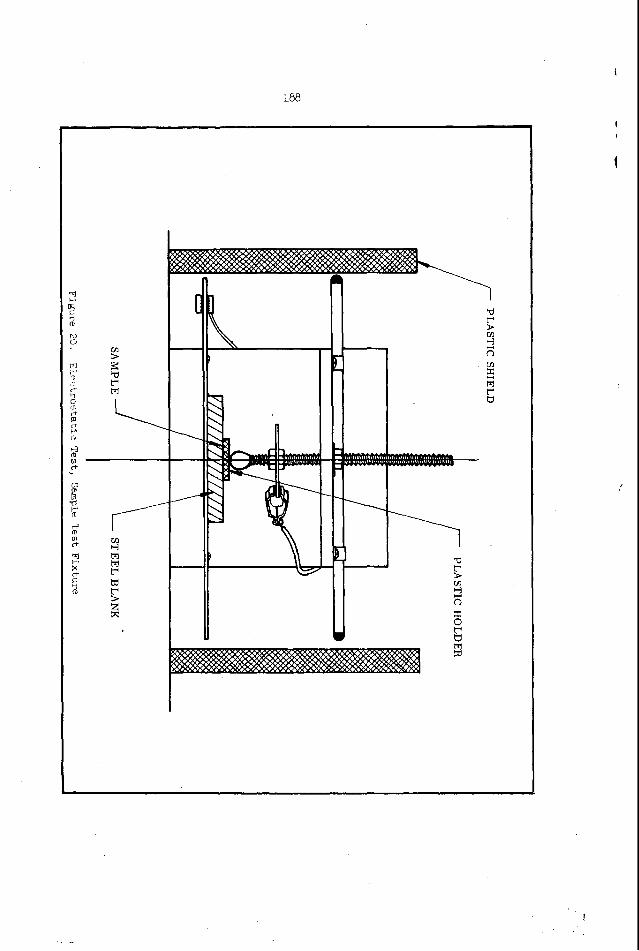
Most of the electrostatic tes t devices used by the various facilities were not permanent and lacked unity of design. Several of the designs used common devices for energy application, such as the use of a phonograph needle for one electrode,but the devices still varied in sample s ize , and sample preparation. It was decided to design a n electrostatic tes te r that would incorporate many of the better features of existing designs to meet program objectives. The electrostatic tes ter and the major subassemblies a r e shown in Figures 17, 18, and 19. A sketch of the sample test fixture is shown in Figure 20. Samples a r e inserted into a plastic holder of a given hole size and then placed on a s teel blank attached to one electrode. electrode i s attached to a s teel ball placed on top of the hole in the plastic holder. The ball is four times the diameter of the sample hole.
The other
The capacitors are charged with a NJE high voltage power supply capable of generating 60,000 volts. Switching i s accomplished with a solenoid operated knife switch t o eliminate switch bounce experiencedwith vacuum switches. Arrangement of the capacitors in a circle with the contacts in the center permits rapid selection of the desired capacitance value.
Detonation Testing
The most important detonation characteristic in propellant processing facilities is the critical diameter. If a critical diameter exists within the maximum diameter of material being processed, then other detonation characteristics such as minimum
'Critical diameter is the minimum charge diameter that will sustain a detonation when initiated by a booster charge greater than the minimum booster o r equal in diameter to the test charge.
\
booster, deflagration-to-detonation, and projectile impact sensitivity will be determined.
After reviewing other facilities, it w a s found that very few improvements were made in the method of determining critical diameters, and that a l l attempts to determine critical diameters of compositions with subcritical diameter samples were unsuccessful.
Two approaches to determine critical diameters with subcritical diameter charges a r e being investigated. The f i rs t i s the development of a relationship between the critical diameter of a material and grain reaction determinations extrapolated to a theoretical detonation temperature and other chemical and physical parameters such a s density, temperature, and confinement. The second method i s a study of the detonation reactivity of subcritical diameter propellant samples when subjected to large booster charges.
INTERPRETATION
The following is a summary of the test techniques and data interpretation for each of the testing devices described.
Friction Analvsis
One Inch Diameter Piston-to-Cup Slurry Tester--The most uniform resul ts were obtained using a sample size of approximately 0.4 gram so the material would not be extruded out of the cup. A vertical force and rotational speed were obtained for which a reference uncured propellant sample would f i re in approximately one minute. A f i re is evidenced by an audible o r visual reaction. If the cup o r piston temperature r ises above 10 degrees Fahrenheit during a tes t , cooling i s provided to maintain a temperature within 10 degrees of room temperature prior to the next test. Ten tests were run on each sample to obtain the minimum, maximum, and average f i re times.
A sensitivity index is established by dividing the average f i re t ime of the test material by the average fire time of the reference material and multiplying by ten. Hazard limits are established based on the index values.
Twelve Inch Diameter Vertical Slurrv Friction Tester--A thin film of propellant is spread around the periphery of the bowl the same width as the friction head. The sample sizes vary between 0.5 and 2 grams. On some tests it is desirable to put the test sample in front of the friction head instead of spreading it around the side of the bowl. The speed and force a r e varied to obtain a f i re point for a reference material of approximately 15 seconds. A f i re is evidenced by an audible o r visual reaction. The temperature of the bowl and friction head i s maintained to within 10 degrees of ambient temperature prior t o each test. One test replaceable metal s t r ips are used on the friction head when conducting standard tests to determine the friction index.
166
The number of tes t s conducted and the evaluation of the test data for establish- ment of a friction index are the same as on the piston-and-cup tests.
Twelve Inch Diameter Horizontal Slurry Friction Tester--The horizontal friction tes ter uses a sample s ize of approximately 5 grams. The rotational speed and force settings, number of tes t s , and data evaluation a r e similar to the vertical tester.
Strip Friction Tester--The most uniform test results were achieved by placing the sample between the s t r ips in front of the rol ler pressure point. The preparation of the sample and uniformity of the s t r ips must be carefully monitored to produce accurate tes t results.
A standard is tested with either beta-HMX (Cyclotetramethylenetetranitramine) explosives or a propellant composition, depending upon the type of test material. The most useful information is obtained by determining a drop height and weight to provide satisfactory results with the standard. Then a l l similar mater ia ls a r e tested using the drop weight and height, with the applied force being varied.
A Bruceton-type analysis is followed to obtain a 50 percent f i re point. The 50 percent f i re point is used t o establish a friction index, as compared to a reference material. A fire is evidenced by an audible o r uisual reaction.
Rotarv Friction Tester--The rotary friction tes te r i s used for two types of tests. One tes t is to establish a rotary friction sensitivity index using a stainless steel shoe and wheel. The other i s a comparative tes t using varying shoe and wheel combinations s imilar to that shown in Figure 21.
The average time-to-fire is used on the standard test t o compute a rotary friction index, which is the average time-to-fire of the tes t material divided by the average time-to-fire of the standard material multiplied by ten.
On the tests using varying wheel and shoe combinations, the data a r e evaluated by plotting the average time-to-fire in seconds versus the radial wheel velocity in feet per second times the applied force in pounds per square inch (Figure 22). By this method, varying wheel and shoe sizes are used and still compared with other tests using different size wheels and shoes.
Impact Analysis
Indirect Impact Tester--Preparation of propellant samples for the indirect impact tes ter is accomplished by slicing the propellant into 0.021 inch thick s t r ips using a microtome cutter. Dried mater ia ls a r e sampled volumetrically. The Bruceton tes t technique is used t o obtain the 0 , 50, and 100 percent f i re points, with the 50 percent f i re point being used for determining the impact index. Beta-HMX is
i
167
I
c
used as a standard; and the reference material, an uncured propellant composition, is used to compute the impact index. The impact index is computed simiIarly to the rotary friction index, or the 50 percent f i re point of the unknown material is divided by the 50 percent fire point of the reference uncured propellant multiplied by ten. A typical test data sheet is shown in Figure 23.
Direct Impact Tester--Because of the difficulty o r t ime consuming efforts in raising o r lowering the weights on the direct impact tes ter , a Probst analysis i s used rather than the Bruceton analysis. The Probst analysis involves conducting 20 tests at each height within the range of the 0 and 100 percent f i re points. Small (0.009 gram) samples a r e used. Propellants are sliced with a microtome cutter and punched out with a circular punch. An audible sound is used to determine whether o r not the material fired.
Autoignition Asalvsis
Autoignitjon tests are conducted with the oven set a t a constant temperature. A thermocouple placed adjacent to the sample records the temperature and the time-to-fire. The temperature i s increased o r decreased until the autoignition characteristics f o r approximately one hour are obtained, similar to the data shown in Figure 24. If a material t o be tested has an unknown autoignition temperature range, a dynatpic temperature environment test is performed on the material with the oven tempeyature increased over a given period of t ime until the f i re point i s reached. These data are then evaluated t o determine the temperature range to b e used.
Electrostatic Analysis
Electrostatic tests are conducted between the ranges of 100 pf to 0 . 1 I.lf capacitance and 100 to 60,000 volts. A 50 percent f i re point is estimated using a Bruceton-type analysis by increasing o r decreasing the voltage. A chart for which voltages, capacitance, and energy levels are displayed is shown in Figure 25. The sensitivity of materials is compared by taking a constant energy line in joules which is tangent to the tes t data curve. This energy value is then used to compute an electrostatic sensitivity index, the same as for the friction and impact tes t data.
U s e of the one test replaceable plastic holders enables rapid testing and uni- formity of sample preparation with a minimum material required.
Detonation Analvsis - ,-
A t the present time, sufficient tes ts had not been conducted to prove the validity of determining critical diameters either by reaction rates or reactivity measurements with laboratory samples.
\
I
168
Tests a r e still being conducted using a standard pipe detonation test setup similar t o that shown in Figure 26. A booster having the same diameter as the test charge is used to ensure adequate boostering, and a charge of sufficient length is used to evidence the reaction. Pin gages a re used to record the shock velocities, and the signals from the gages are recorded with a coded pin mixer system to ensure more reliable da ta pickup.
CONCLUSION
The friction, impact, autoignition, and electrostatic tes t equipment and techniques developed during this program enable rapid and inexpensive determination of the hazardous characteristics for propellant constituents and compositions present in propellant manufacturing and storage facilities.
This equipment and these techniques are providing better utilization of pro- pellant development facilities and manpower because hazard test data are being obtained with less tes t delays than was possible with previous designs and techniques.
169
i I
b
I t t
Y
- C H E M I C A L C O R P O R A T I O N W.,.,C* 0 1 " 1 . 1 0 * . ..lG"." 511. . " 1 . "
Figure 1. One Inch Piston and Cup Slurry Friction Tester
170
12 INCH BOWL-VERTICAL SCRAPER
DIRECTION OF ROTATIOX
d DIRECTION OF
ROTATION
DIRECTION OF ROTATION
SAMPLE C -
1 INCH PISTON AND CUP
I 12 INCH BOWL-HORIZONTAL SCRAPER
Figure 2
Application of Forces i n Slurry F r i c t i o n Testers
k
\
I 1
-4 C H E M I C A L C O w r u n r i r u n
I . S . T C * 0 1 " 1 1 1 0 * . .RlG...* CII., "I." ~-
Figure 3. Twelve Inch Bowl Vertical Slurry Friction Tester
I (I
C H E M I c 4 L c 0 R P 0 R A 7: W I S L I C " 0 1 " 1 ~ , 0 * . . " , G * . " c ,,I) " I . "
Figure 4. Twelve Inch Bowl Horizontal Slurry Friction Tester
- C H E M I C A L C O R P O R A T I O N I . , . 7C* 0 1 " 1 , 1 0 * . a " , r * . * C I , " ) " I . "
Figure 6 . Strip Friction Tester
' .
\
17 5
STRIPNO. 1 1
0
STRIPNO. 1
Figure 7 . Detail of S t r i p Friction Tester
176
P I
177
I
I
Figure 10. Indirect Impact Tester ,...,,, 0 1 . . 1 . 1 0 * * ..lo*." C I I . . " I . *
~ STEEL DISC - SANOPAPEK
-
BRASS Cl lP
d- r-
Figure 1:
Details of I n d i r e c t Impact Tester 9~ Assembly
7’ SAMPLE
HOLDER
180
b
n
P
Fimre 12. Direct Impact Tester
181
2.50 7'0 4,000 GRAM FA LLING WEIGHT
FORCE
i" Figure 13
S t r i k e r Impacting on Sar.ple in n i r e c t Impact, Z e s t
J
. . . 182
183
\ SUPPORTROD,
THERMOCOUPLE
SAMPLE IN GLASS VILE
Figure 15
Autoignition T e s t for Liquid Samples
184 ~
T . C . OLTPI-T TO S r R I P CHART RECORCE R
O I E S
Ro\
Figure 16
Autoignitj.on Test for Solid Samples
185
! I
I
187
m P
I
r
t D A T K WORU ORDER NO.
I
I
I
PST NO.
O P E R A T O R
',
S*YPLK
001 E X P E R I M E N T A L
Y Propellant
13. A I M P A C T I N D E X
9.4
E = EXPLOSIONS e ASSUMED EXPLOSIONS N = N O EXPLOSIONS
RESULT
OF aD0 AUT0lt lHl~i0N ESDP NO. 63-8 REV 1 MI N
V n = ASSLIMED NO EXPLOSIONS
250 390 400 45U 415 500 525 No fire 24 hr 64 25 18 15 6
DETONABILITY . ESOPNO. 63-7 REV I THE S A M P L E m f D I D N O T ) DETONATE IN A 2 INCH CHARGE DIAMETER.
NOTE: 1. A FIVE POUND DROP WEIG'fT IS USE0 IN IMPACT TESTING. l H E HMX STANDARD 50% EXPLOSION WAS% INCHES.
- 2. SENSITIVITY COMPARED WITH STANDARD PROP_EL_LANT WITH AN ASSIGNED IMPAC-T I N D E X O F io. .
ANY SAMPLE WTH AN IMPACT INDEX LOWER THAN 5 IS IN THE CRITICAL RANGE AND EXTREME CARE OlOULD BE EXERCISED IN MANUFACTURE AND HANDLING.
M re no. t u 1
c) w c) w L i t t t t e ; I ;I
0 IC 4- 0. c o o I.; c c. C L 3 l i 0 0 0 0
I .
0 3 0 0 0 0 o c
I
C
C
b
h
PENTOLITE BOOSTFR a PENTOLITE BOOSTER ( A S R EQUIR ED)
COMP R OR PENTOLITE EXPLOSIVE DONER (MlN L/D OF :)