+ All Categories
Home > Documents > Test Protocols for Advanced Inverter Interoperability...

Test Protocols for Advanced Inverter Interoperability...

Date post: 04-Apr-2018
Category:
Upload: phamnguyet
View: 217 times
Download: 2 times
Share this document with a friend
22
SANDIA REPORT SAND2013-9880 Unlimited Release Printed November 2013 Test Protocols for Advanced Inverter Interoperability Functions Main Document Jay Johnson, Sigifredo Gonzalez, Mark E. Ralph, Abraham Ellis, and Robert Broderick Prepared by Sandia National Laboratories Albuquerque, New Mexico 87185 and Livermore, California 94550 Sandia National Laboratories is a multi-program laboratory managed and operated by Sandia Corporation, a wholly owned subsidiary of Lockheed Martin Corporation, for the U.S. Department of Energy’s National Nuclear Security Administration under contract DE-AC04-94AL85000. Approved for public release; further dissemination unlimited.
Transcript

SANDIA REPORT SAND2013-9880 Unlimited Release Printed November 2013

Test Protocols for Advanced Inverter Interoperability Functions – Main Document

Jay Johnson, Sigifredo Gonzalez, Mark E. Ralph, Abraham Ellis, and Robert Broderick

Prepared by Sandia National Laboratories Albuquerque, New Mexico 87185 and Livermore, California 94550

Sandia National Laboratories is a multi-program laboratory managed and operated by Sandia Corporation, a wholly owned subsidiary of Lockheed Martin Corporation, for the U.S. Department of Energy’s National Nuclear Security Administration under contract DE-AC04-94AL85000.

Approved for public release; further dissemination unlimited.

Issued by Sandia National Laboratories, operated for the United States Department of Energy by Sandia Corporation.

NOTICE: This report was prepared as an account of work sponsored by an agency of the United States Government. Neither

the United States Government, nor any agency thereof, nor any of their employees, nor any of their contractors, subcontractors,

or their employees, make any warranty, express or implied, or assume any legal liability or responsibility for the accuracy,

completeness, or usefulness of any information, apparatus, product, or process disclosed, or represent that its use would not

infringe privately owned rights. Reference herein to any specific commercial product, process, or service by trade name,

trademark, manufacturer, or otherwise, does not necessarily constitute or imply its endorsement, recommendation, or favoring by

the United States Government, any agency thereof, or any of their contractors or subcontractors. The views and opinions

expressed herein do not necessarily state or reflect those of the United States Government, any agency thereof, or any of their

contractors.

Printed in the United States of America. This report has been reproduced directly from the best available copy.

Available to DOE and DOE contractors from

U.S. Department of Energy

Office of Scientific and Technical Information

P.O. Box 62

Oak Ridge, TN 37831

Telephone: (865) 576-8401

Facsimile: (865) 576-5728

E-Mail: [email protected]

Online ordering: http://www.osti.gov/bridge

Available to the public from

U.S. Department of Commerce

National Technical Information Service

5285 Port Royal Rd.

Springfield, VA 22161

Telephone: (800) 553-6847

Facsimile: (703) 605-6900

E-Mail: [email protected]

Online order: http://www.ntis.gov/help/ordermethods.asp?loc=7-4-0#online

3

SAND2013-9880

Unlimited Release

Printed November 2013

Test Protocols for Advanced Inverter Interoperability Functions – Main Document

Jay Johnson, Sigifredo Gonzalez, Mark E. Ralph, Abraham Ellis, and Robert Broderick

Sandia National Laboratories

P.O. Box 5800

Albuquerque, New Mexico 87185-1033

Distributed energy resources (DER) such as photovoltaic (PV) systems, when deployed in a

large scale, are capable of influencing significantly the operation of power systems. Looking to

the future, stakeholders are working on standards to make it possible to manage the potentially

complex interactions between DER and the power system.

In 2009, the Electric Power Research Institute (EPRI), Sandia National Laboratories (SNL)

with the U.S. Department of Energy (DOE), and the Solar Electric Power Association (SEPA)

initiated a large industry collaborative to identify and standardize definitions for a set of DER

grid support functions. While the initial effort concentrated on grid-tied PV inverters and

energy storage systems, the concepts have applicability to all DER. A partial product of this

on-going effort is a reference definitions document (IEC TR 61850-90-7, Object models for

power converters in distributed energy resources (DER) systems) that has become a basis for

expansion of related International Electrotechnical Commission (IEC) standards, and is

supported by US National Institute of Standards and Technology (NIST) Smart Grid

Interoperability Panel (SGIP). Some industry-led organizations advancing communications

protocols have also embraced this work.

As standards continue to evolve, it is necessary to develop test protocols to independently

verify that the inverters are properly executing the advanced functions. Interoperability is

assured by establishing common definitions for the functions and a method to test compliance

with operational requirements. This document describes test protocols developed by SNL to

evaluate the electrical performance and operational capabilities of PV inverters and energy

storage, as described in IEC TR 61850-90-7. While many of these functions are not currently

required by existing grid codes or may not be widely available commercially, the industry is

rapidly moving in that direction. Interoperability issues are already apparent as some of these

inverter capabilities are being incorporated in large demonstration and commercial projects.

The test protocols are intended to be used to verify acceptable performance of inverters within

the standard framework described in IEC TR 61850-90-7. These test protocols, as they are

refined and validated over time, can become precursors for future certification test procedures

for DER advanced grid support functions.

4

ACKNOWLEDGEMENTS

Sandia National Laboratories acknowledges the support of the U.S. Department of

Energy Solar Energy Program that sponsored the development of this protocol and of the

Electric Power Research Institute, who is leading the related effort to develop definitions

for utility-based functions for advanced inverters and Distributed Energy Resource

controls. SNL also acknowledges SRA International for their valuable technical review

and content contributions.

5

CONTENTS

1. INTRODUCTION ...................................................................................................................... 7 1.1 Background ..................................................................................................................... 7 1.2 Objective and Purpose .................................................................................................... 8 1.3 Advanced DER Inverter Functions ................................................................................. 8 1.5 Modes of Communication and Interaction with DER .................................................. 12

1.6 Communication Protocols ............................................................................................ 13

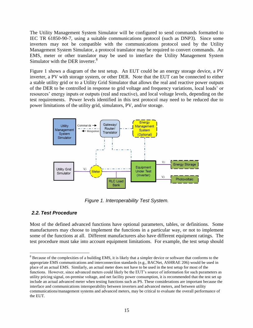
2. GENERAL TEST REQUIREMENTS ..................................................................................... 14 2.1. Test Setup.................................................................................................................... 14 2.2. Test Procedure ............................................................................................................ 15

3. REFERENCES AND RELEVANT STANDARDS ................................................................. 19

FIGURES and TABLES

Table 1. Advanced DER Inverter Functions contained in IEC TR 61850-90-7 ............................. 9 Figure 1. Interoperability Test System.......................................................................................... 15

6

ACRONYMS

AMI Advanced Metering Infrastructure

ANSI American National Standards Institute

DER Distributed Energy Resources

DMS Distribution Management System

DOE Department of Energy

ECP Electrical Coupling Point

EMS Emergency Management System

EPRI Electric Power Research Institute

EPS Electric Power System (electric utilities or their surrogates)

EUT Equipment Under Test

IEC International Electrotechnical Commission

IEEE Institute of Electrical and Electronics Engineers

NEC National Electric Code

NFPA National Fire Protection Association

NIST National Institute for Standards and Technology

NTP Network Time Protocol

PV Photovoltaic

RLC Resistive/Inductive/Capacitive

SEP Smart Energy Profile

SEPA Solar Electric Power Association

SGIP Smart Grid Interoperability Panel

SOC State Of Charge

SNL Sandia National Laboratories

SNTP Simple Network Time Protocol

TCP/IP Transmission Control Protocol/Internet Protocol

UL Underwriters Laboratories

7

1. INTRODUCTION

1.1 Background

Distributed energy resources (DER) such as photovoltaic (PV) systems, when deployed in a large

scale, are capable of significantly influencing the operation of power systems. Looking to the

future, stakeholders are working on standards to make it possible to manage the potentially

complex interactions between DER and the power system. The interconnection of DER to the

grid is subject to performance and safety requirements that vary significantly among

jurisdictions. Fulfillment of some of these requirements often requires that DER capabilities be

certified by an independent testing entity. These codes and certification requirements are in a

state of evolution worldwide, and the trend is toward expanding grid support features; this

requires greater interoperability between DER and utility or energy management systems.

In North America, for example, the performance requirement for DER is defined in the IEEE

15471. (A revision to IEEE 1547, designated 1547a, is being prepared that will incorporate some

of the advanced functionality defined in IEC TR 61850-90-7.) UL 17412 is a certification test

procedure designed to be used in conjunction with and to supplement IEEE 1547, in order to

ensure safe operation of certain equipment associated with distributed generation, in compliance

with the U.S. National Electrical Code, NFPA 70. As the level of distributed generation

increases on the electric power system, the distributed generation sources may be called upon to

perform additional functions that are not defined in the current version of the IEEE 1547

standard. It is expected future grid codes will contain allowances for an expanded set of DER

functions, and some of these additional functions may be implemented and controlled through

communications (from a utility or grid/micro-grid controller or from a facility control system or

customer input) and/or from firmware installed in DER device(s).

In 2009, the Electric Power Research Institute (EPRI), Sandia National Laboratories (SNL) with

the U.S. Department of Energy (DOE), and the Solar Electric Power Association (SEPA)

initiated a large industry collaborative to identify and standardize definitions for a set of grid

support functions. While the initial effort concentrated on grid-tied PV inverters and energy

storage systems and utility-generated commands and communications, the concepts have

applicability to all DER. The International Electrotechnical Commission (IEC) published a

Technical Report3 (IEC TR 61850-90-7) largely based on this on-going effort, and has become

the basis for possible enhancements to the IEC61850-7-420 standard4. This work is also

supported by US National Institute of Standards and Technology (NIST) as part of the Smart

Grid Interoperability Panel (SGIP) Priority Action Plan 7. This effort is also of interest to the

commercial communications protocols community. For example, a DNP3 Application Note

(DNP 2010) was written for several advanced functions.5

1 IEEE Standard 1547-2003, Interconnecting Distributed Resources With Electric Power Systems.

2 Underwriters Laboratories 1741, Inverters, Converters, Controllers and Interconnection System Equipment for Use

With Distributed Energy Resources 3 IEC Technical Report IEC-61850-90-7 — Communication networks and systems for power utility automation –

Part 90-7: Object models for power converters in distributed energy resources (DER) systems Edition 1.0(Feb

2013). 4 IEC 61850-7-420 — Communications systems for Distributed Energy Resources (DER) – Logical nodes

5 DNP3 is a communications protocol widely used by US utilities to communicate with distribution system assets.

8

1.2 Objective and Purpose

The objective is that the test protocols developed here, as improved over time, may become

precursors for future industry-standard certification testing procedures. However, the following

important caveats should be kept in mind:

The functions contained in IEC TR 61850-90-7 are not interconnection requirements.

The establishment of specific functionality that is required for interconnection is in the

purview of Grid Codes issued by standards development organizations such as IEEE,

IEC, and ANSI, and by reliability entities.

The test protocols described in this document are not intended for equipment

certification. The protocols provide general guidelines to evaluate emerging functionality

and interoperability on a consistent basis in a laboratory environment.

The test procedures observe and record the electrical output behavior of the Equipment

Under Test (EUT), but there may be different ways for the EUT to execute the function

or transition from one state to another. It should be recognized that IEC TR 61850-90-7

does not specify what performance is required for DER. It only describes how the

function can be configured.

The test protocols described in this document establish a common set of procedures to verify

through direct testing conformance with respect to the functions described in IEC TR 61850-90-

7. Verification of compliance of a certain device or EUT involves testing two performance

aspects:

(1) Communications – determining whether and how the EUT is receiving and understanding

the request or input (communications);

(2) Electrical – determining if the EUT responds appropriately to the input(s) by initiating

the correct commands to the electrical and mechanical equipment (control logic), and

whether the equipment responds properly to those control commands.

The communications aspects of the interoperability testing will be to verify that the EUT can

process inputs provided using a standard communications format. The electrical aspects will

examine how the EUT performs the functions or task(s) listed in IEC TR 61850-90-7. (A test

protocol for an additional function, Low/High Frequency Ride Through – L/HFRT – has also

been developed, as the California Energy Commission and the California Public Utilities

Commission are considering making a L/HFRT a required function for DER inverters under their

Rule 21.)

SNL has developed test protocols for the functions listed in Table 1, as described in Section 2

and the appendices of this document. The intent of this on-going work is to refine this set of test

protocols, in collaboration with national and international stakeholders.

1.3 Advanced DER Inverter Functions

This section provides a brief summary of the advanced DER inverter functions documented in

IEC TR 61850-90-7. Table 1 lists the IEC advanced management and information exchange

functions. The messages associated with each of the functions are characterized as commands,

requests, or instructions to configure performance/control characteristics. Requests or

commands may or may not be followed due to equipment limitations or local override by the

9

equipment owner. Instructions to configure performance characteristics are used to specify under

what conditions a command will be executed and how.

Table 1. Advanced DER Inverter Functions contained in IEC TR 61850-90-7 Command Function Description Type

INV1 Connect/Disconnect Physically connect or disconnect from grid Command

INV2 Adjust Maximum Generation Level

Set maximum generation level at Electrical Coupling Point (ECP)

Command

INV3 Adjust Power Factor Issues a power factor angle value Command

INV4 Request Active Power Request charging or discharging of the storage system Request

INV5 PV/Storage Functions Change the signal parameters for the storage system Request

VV11 Volt-Var mode Provide vars with no effect on watts Set Parameter

VV12 Volt-Var mode Provide maximum vars constrained by WMax Set Parameter

VV13 Volt-Var mode Establish fixed var settings Set Parameter

VV14 Volt-Var mode No var support Set Parameter

FW21 Set maximum power output Active power reduction due to high frequency Set Parameter

FW22 Set maximum power output Modify frequency-watts-delivered or watts-received curve according to time of day or other parameters

Set Parameter

TV31 Dynamic reactive power support Provide var support at times of abnormally high or low voltage

Set Parameter

L/H VRT Connect/disconnect settings Set voltage ride-through or disconnect requirements Set Parameter

WP41 Power factor settings Set power factor in response to feed-in power Set Parameter

WP42 Power factor settings Modify power factor-watts curve according to other parameters

Set Parameter

VW51 Set output to smooth voltage deviations

Voltage-watt curve of generator output based on various parameters

Set Parameter

VW52 Set output to smooth voltage deviations

Voltage-watt curve of storage charge/discharge output Set Parameter

TMP Temperature mode behavior Temperature-based curves Set Parameter

PS Signal mode behavior Mode curves based on utility signal Set Parameter

DS91 Modify DER Inverter Settings Set default ramp rate, min. storage level, max. storage charge/discharge rate

Command

DS92 Event/History Logging Request event logs Command

DS93 Status Reporting Request inverter status Command

DS94 Time Synchronization Set inverter time Command

L/H FRT* Connect/disconnect settings Set frequency ride-through or disconnect requirements Set Parameter

*function required under CPUC/CEC Rule 21, not part of IEC TR 61850-90-7

IEC TR 61850-90-7 characterizes the functions of Table 1 as:

INV1 through INV5: Immediate control functions

VV11 through VV14: Volt-var management modes

FW21 and FW22: Frequency-watt management modes

TV-31: Dynamic reactive current support during abnormally high or low voltage levels

L/H VRT Functions for “must disconnect” and “must remain connected”

WP41 and WP42: Watt-triggered behavior modes

VW 51 and VW52: Voltage-Watt Management Modes

DS91 through DS94: Parameter Setting and Reporting

In response to control signals or internal settings, DER inverters will initiate the following

actions, which roughly correspond to the Table 1 functions following each action in brackets:

Connect/Enable [INV1, INV4, and L/H VRT]

Disconnect/Disable [INV1, INV4, and L/H VRT]

Set output level [INV2, INV5, FW, VW]

Set power factor [INV3, VV, TV, WP]

Change control parameters [DS91, TMP, PS]

10

Log history (data and/or activity) [DS92]

Report status or event [DS93]

Synchronize time [DS94]

Associated with each control function in IEC TR 61850-90-7 are various parameters and

characteristics that dictate how, when, and under what circumstances the command will be

executed. These parameters and characteristics that determine DER inverters will perform these

functions may include the intrinsic capabilities of the DER, various externally-set parameters,

locally measured or sensed conditions (e.g., voltage level, frequency, temperature, rate of change

in voltage), and outside inputs (such as utility signal, EMS command, or user-entered command).

Testing the ability of the EUT to execute a particular function requires testing alternate sets of

parameters and commands that characterize how the function is executed.

There are different methods to manage DER behavior. These can be categorized as follows:

Modes consist of pre-established groups of settings that can enable autonomous DER

behavior, where the DER senses local conditions and, using the settings defined for that

mode, responds appropriately. This approach minimizes communications requirements

and permits more rapid responses when the communications link is inoperable. Modes

are often established for volt-var control; frequency-watt control; charging/discharging

storage; and other, often complex, actions. They may be communicated remotely and/or

programmed directly into the inverter controller. A mode will be defined by:

o The parameters or other inputs to be sensed

o The actions to be taken (command, value, time of initiation) based on those inputs

o The priority of the mode

o How the parameters of the mode can be modified

Schedules are a type of mode, where the key input is a time sequence and behavior

instructions for each time interval, to be executed autonomously. Once established,

schedules may operate for a specific time period or indefinitely. For example, a schedule

may establish what modes to use during weekdays versus weekends. In order to prevent

simultaneous operations by numerous DER, a response time window with a random time

delay may be built into the schedule (see “response time” below).

Curves and tables provide settings or actions to take based on the value of an input.

Such inputs could include temperature, local voltage measurements, local energy use

(i.e., load) level or energy production (e.g., storage output), utility signal, etc. A table

based on utility pricing signals (broadcast as in critical peak pricing; stored in a schedule

as in time of use rates; or a combination) may initiate charge or discharge actions for

energy storage. The power factor (i.e., displacement factor) of the DER inverter output

may be set using a curve dependent on system voltage (see, e.g., Figure 15 in IEC TR

61850-90-7).

Response times, rate of response, and timeout period define, respectively, 1) how soon

an inverter action is initiated after the command is received, 2) how quickly the desired

inverter output is reached, and 3) how long the change from default setting or mode is in

effect if a command to the contrary is not received.

11

o The response time is the time period over which a DER inverter should execute

the specific action that was requested. For safety-related reasons a short

maximum response time (on the order of cycles or seconds) may be specified. A

longer response time could make sense for economically- or efficiency-motivated

reasons. For example, a DER response time on the order of 5 minutes may be

adequate for economic dispatch of generation.

o A random time delay between an inverter’s receiving a command and executing

it may be specified. Immediate and simultaneous action by a large number of

DER inverters should be avoided because it could affect system stability or cause

unintended transients and actions of system protection devices.

o The ramp rate is the constraint on how quickly the DER should change from its

present output level (active or reactive) to the desired output level. Specific

commands or schedules may specify ramp rates; the DER’s default ramp rate

would be used if no ramp rate is specified6.

o The Timeout Period parameter guards against the possibility that a missed or lost

communication to the DER could affect normal operations. If no “reinforcing” or

“repeat” command is received by the DER within the timeout period, then the

DER will automatically revert to its default state.

Hierarchy of control is inherent in power system management, where, e.g., system

protection and reliability functions would take precedence over economic dispatch. IEC

TR 61850-90-7 begins to address this, in differentiating among levels for initiating

commands (e.g., autonomous versus broadcast), but currently requires only that the DER

inverter implement the last command received. Therefore, uniform methods of specifying

and testing control hierarchy are presently beyond the scope of this test protocol. This

means that the test protocols provide for the equipment under test to be a single inverter

or DER device – not multiple interconnected inverters.

IEC TR 61850-90-7 lists many advanced functions, and also several ways each function could

be implemented. Not all inverters may have advanced functional capability; for example, at

present many inverters do not have the capability to adjust the power factor of their output. As

shown above, there are also many options for how an advanced function is implemented (e.g.,

based on local conditions, schedule, table look-up, and/or utility signal; with random time delay

before start; constrained by a ramp rate; with a timeout period; etc.) This protocol is designed to

verify whether a DER inverter executes a function in accordance with IEC TR 61850-90-7, if

the inverter claims to have the capability to implement that function. Therefore, the first step in

testing an inverter is to develop a “Function Capabilities Table” (FCT) that specifies for the

inverter which functions and options for executing those functions it has. The FCT will serve to

define which tests, and groups of parameters for the tests, are to be used for an inverter.

6 On a DER inverter, ramp rate constraints may depend upon the operating mode. For example, a PV inverter with

storage has different characteristics if power comes from PV or from battery.

12

1.5 Modes of Communication and Interaction with DER

Inputs to inverters may come from locally-sensed conditions (e.g., voltage; or inputs from a

directly-connected switch or keypad); from other control systems (e.g., building energy

management systems [EMS] or smart meter); or from a utility (either from a central broadcast or

from a utility-operated local distribution management system). Thus, the utility or Electric Power

System (EPS) may interact directly with inverters (Direct Management), or indirectly through an

external control system such as an EMS (Indirect Management). This test protocol will address

both methods: Direct Management and Indirect Management. Indirect Management involves the

use of EMSs which may include the ability to translate the commands received from the EPS to

another communications protocol to interface with the DER. In such cases, the test protocols

assume that EMS or smart meter is part of the EUT. Specific testing of how the EMS interfaces

with the DER inverter is beyond the scope of this test protocol.

Broadcast or multicast commands from the EPS can be sent to multiple interoperable inverters.

With broadcast commands, there is no expectation of a communication response from the

inverter. Broadcast commands may include addresses. A message can be sent, for example, to

“all” inverters, to “all inverters on PV panels,” to “all inverters on feeder 2235,” to “all inverters

in dispatch group 7,” etc., or even to logically combined combinations of such address groups.

However, since the protocol is designed to test only one DER inverter at a time, verifying the

inverter addressing and group addressing capabilities is beyond the scope of this test protocol.

The test will only include the inverter’s response to a broadcast command.

There are at least 3 levels of information exchange that could set inverter operating modes, as

defined in IEC TR 61850-90-77:

Autonomous DER behavior responding to local conditions. The DER controller uses a

pre-set mode or schedule that responds to locally-sensed conditions. Remote

communications are not required, although such communications may be used to change

the parameters of the local control logic or schedule. Remote communications may also

be used to change the DER from autonomous control to another mode of control or

change control parameters. The data on local conditions may come from sensors (e.g.,

voltage, frequency, temperature, solar insolation); “smart” meters (e.g., local demand

level, voltage or reactive power consumption); time of day; a broadcast signal; and/or

customer-entered commands.

DER management system interactions with other control systems. The DER

controller interacts with one or more external management systems. These management

systems will coordinate multiple DER in order to dispatch and otherwise control a variety

of assets and asset types in order to best meet an objective. Examples of such external

control systems include a microgrid controller, a building or campus energy management

system, or a utility distribution management system.

7 The information exchanges identified in IEC TR 61850-90-7 have been expanded to include 1) local inputs from a

variety of sources and sensors including customer-entered commands; 2) information from other control systems

such as building or facility energy management systems; and 3) utility broadcast commands that may be directed to

a specific subset or address group of inverters on the system.

13

Broadcast/Multicast. This consists of one-way notifications with large numbers of DER

systems (without one-to-one communications). Such notifications could be pricing

signals, emergency signals, or requests for specific DER actions or changes of operating

modes. Typically such notifications would originate with the utility or energy services

provider. While the signal would be broadcast to all DER, it could include addresses, so

that, for example, only inverters in one area would act upon the broadcast signal.

1.6 Communication Protocols

In an actual application, the communication-enabled functionality would be implemented in one

of several possible standard communications protocols. There are no explicit requirements in

IEC TR 61850-90-7 or in the test protocols with regard to the communication protocol that the

EUT needs to use. The only requirement is that the laboratory test equipment have the ability to

interface with the EUT, either directly or through a suitable translator.

There can be several possible communication interfaces between the utility EPS and inverters.

Communications can also take place over multiple physical layers: direct wire, fiber, radio

frequency, power line carrier, etc.). EPSs in the United States are most likely to use DNP3 to

communicate with controllable distribution system assets using broadcast commands.

This test protocol assumes a simple scheme where the utility or DMS issues commands or

configuration instructions to inverters that may go through several devices (EMS, etc.); however,

it is assumed that those devices are transparent to the command.

14

2. GENERAL TEST REQUIREMENTS

2.1. Test Setup

This section provides general guidelines of the test setup and test equipment requirements to

verify DER inverter functional interoperability. The specific testing requirements may vary

widely depending on the purpose of the test (i.e., which set of advanced functions are being

tested).

A typical laboratory setup for the Equipment Under Test (EUT) should include the following:

A Utility Grid Simulator or grid connection, which provides a power source or a sink

to the DER. Some of the functions do not require control of voltage or frequency, such as

commands to connect or disconnect (INV1), and connection directly to the grid would

suffice. But to test the full range of the parameters that might trigger the function or

affect how it is implemented, a range of grid conditions would be required. Therefore, a

grid simulator will usually be more appropriate for the test setup than a connection to the

actual grid. [Grid Simulator needed for testing many INV, and all FW, TV, L/H VRT,

VW commands.]

A Utility Management System Simulator, which provides, using the proper

communication protocols, utility-generated signals, information, commands and requests.

The Utility Management System Simulator will be used to messages to the EUT, as well

as to change the parameters that govern the actions and responses of the EUT (see

Section 2.) The messages will be formatted according to IEC TR 61850-90-7 and

implemented in a suitable communications protocol. [Utility Management Simulator or

equivalent needed to generate and “broadcast” commands for the communications

portion of all the functions.]

The Equipment Under Test (EUT), which includes the inverter and controls. The

inverter could be connected to a PV array and/or an energy storage device. Because the

testing will call for varying the output levels available from the PV array [INV2, INV3,

INV4, VV or WP ] or the state of charge of the energy storage system [INV4 or INV5], a

PV simulator may be used instead of an actual PV array, and an energy storage simulator

may be used in place of an actual battery.

Optional Load Simulator, an RLC load bank that can provide time-varying real and

reactive electrical loads to be served by the Utility Grid Simulator and/or the EUT. [Load

bank is used to limit the amount of power the utility simulator has to sink when testing

functions requiring the grid simulator, e.g., many INV, and all FW, TV, L/H VRT, VW

functions.]

Sources for Local Inputs to the DER, which could include a meter, an EMS, or other

controls or sensors. Inputs such as temperature and time could be provided by the Utility

Management Simulator, the Utility Grid Simulator, and/or local sensors or signal

generators connected directly to inputs of the EUT. [Such local inputs are needed only

when testing INV functions whose parameters are defined by curves or tables that include

such local conditions, and for testing TMP functions.]

15

The Utility Management System Simulator will be configured to send commands formatted to

IEC TR 61850-90-7, using a suitable communications protocol (such as DNP3). Since some

inverters may not be compatible with the communications protocol used by the Utility

Management System Simulator, a protocol translator may be required to convert commands. An

EMS, meter or other translator may be used to interface the Utility Management System

Simulator with the DER inverter.8

Figure 1 shows a diagram of the test setup. An EUT could be an energy storage device, a PV

inverter, a PV with storage system, or other DER. Note that the EUT can be connected to either

a stable utility grid or to a Utility Grid Simulator that allows the real and reactive power outputs

of the DER to be controlled in response to grid voltage and frequency variations, local loads’ or

resources’ energy inputs or outputs (real and reactive), and local voltage levels, depending on the

test requirements. Power levels identified in this test protocol may need to be reduced due to

power limitations of the utility grid, simulators, PV, and/or storage.

Figure 1. Interoperability Test System.

2.2. Test Procedure

Most of the defined advanced functions have optional parameters, tables, or definitions. Some

manufacturers may choose to implement the functions in a particular way, or not to implement

some of the functions at all. Different manufacturers also have different equipment ratings. The

test procedure must take into account equipment limitations. For example, the test setup should

8 Because of the complexities of a building EMS, it is likely that a simpler device or software that conforms to the

appropriate EMS communications and interconnection standards (e.g., BACNet, ASHRAE 206) would be used in

place of an actual EMS. Similarly, an actual meter does not have to be used in the test setup for most of the

functions. However, since advanced meters could likely be the EUT’s source of information for such parameters as

utility pricing signal, on-premise voltage, and net facility power consumption, it is recommended that the test set up

include an actual advanced meter when testing functions such as PS. These considerations are important because the

interface and communications interoperability between inverters and advanced meters, and between utility

communications/management systems and advanced meters, may be critical to evaluate the overall performance of

the EUT.

16

allow for testing of inverter functionality without conflict with voltage and frequency protection.

The source(s) of input signals or locally sensed conditions should be enumerated. For example, is

local voltage sensed through a potential transducer (PT) directly connected to the EUT or

through the smart meter? The implication is that the test procedures need to be customized to

some extent.

The test engineer should have knowledge of which of the possible options or capabilities for the

functions (as listed in IEC TR 61850-90-7) are implemented in their EUT. A list of tables,

modes, default parameters, curves, schedules, control logic, and permissible ranges of parameters

should also be provided by the inverter manufacturer. The hierarchy among command functions

and the conditions for switching from one mode to another should also be provided. If the EUT

technical specifications are insufficient to setup the interoperability test, the manufacturer should

be consulted. These capabilities and options are recorded in a Function Capabilities Table (FCT)

in order to define the specific tests, and the parameters of those tests, to be conducted.

For each function being tested, the general test procedure is as follows:

Review manufacturer specifications related to the implementation of standard functions

and review communications interface requirements. Prepare a FCT and tailor the test

setup and the test sequence accordingly.

EUT is connected to the sources and sinks under normal operating conditions and for a

period of 5 minutes. This is in order to verify that the EUT is operational and stable.

Verification of communications compatibility. This can be done by issuing a status

request to the EUT (DS93 function).

Test communications functionality. This is performed by issuing a command (as defined

in IEC TR 61850-90-7) to the EUT. The purpose is to establish how the EUT implements

the function command.

Test the electrical behavior to determine if the DER successfully executed the

communicated command.

Analysis of the test results.

EUT input and output voltages, currents, reactive power, apparent power, and active power will

be measured to observe the action taken in response to the commands. Sufficient electrical

measurements should be taken to fully characterize the electrical response or behavior of the

EUT. The sampling rate and test duration should be adequate according to the nature of the

electrical behavior being evaluated. Points to be measured include:

AC voltage at the point of connection

AC current out of the EUT

Frequency at the point of connection

Active and Reactive power at the point of connection

DC voltage of the energy storage device

Current in to and out of the energy storage

DC voltage of the PV array or PV simulator

DC current out of the PV array or. PV simulator

17

Some of the status reporting and data logging can be accomplished using the DS92 and DS93

commands, with the person conducting the test issuing the DS93 command through the Utility

Management System simulator. However, it might be desirable to use a faster sampling rate than

possible through utility-issued DS93 commands; that will be accomplished by directly

monitoring the outputs of the Equipment Under Test (EUT) (e.g., inverter outputs ) (current,

voltage, power factor) with appropriate instrumentation and data loggers.

For each test, the following will be logged:

Time (in seconds)

o command is sent

o response is received

o relevant behavior is observed

o alarms generated

Command

o message sent

o response received

o status reports generated and transmitted by the DER

o commands received (and responses) logged

Electrical Response (Behavior)

o time-synchronized data of relevant behavior

Test sequences may be repeated as needed to verify response to external variables (temperature

effects, power disturbances, etc.). Additionally, some commands such as power level are not

binary; therefore, it may be appropriate to verify interoperability and performance at several

power levels.

Appendices 1 through 20 provide the test protocol for the functions in Table 1, as well as for

some of the parameters associated with how those functions are executed:

Appendix 1: Function INV1 – Connect/Disconnect

Appendix 2: Function INV2 – Adjust Maximum Generation Level Up/Down

Appendix 3: Function INV3 – Adjust Power Factor

Appendix 4: Function INV4 – Request Active Power from Storage

Appendix 5: Function INV5 – Signal for Charge/Discharge Action

Appendix 6: Function VV – Provide watts and vars as specified

Appendix 7: Function FW – Set real power output in response to system frequency

Appendix 8: Function TV – Provide var support at times of abnormal voltage

Appendix 9: Function L/H VRT – Set settings for voltage ride through or disconnect

Appendix 10: Function WP – Set power factor and watts output

Appendix 11: Function VW – Specify voltage-watt curve based on various parameters

Appendix 12: Function TMP – Specify temperature-based parameter curves

Appendix 13: Function PS – Mode curves based on a utility signal

Appendix 14: DS92 – Event/History Logging

Appendix 15: DS93 – Status Reporting

Appendix 16: DS94 – Time Synchronization

18

Appendix 17: Time Window and Random Time Delay

Appendix 18: Ramp Rate

Appendix 19: Command Timeout

Appendix 20: L/HFRT – Low and High Frequency Ride Through

Appendix A – Event Log Fields

Appendix B – Potential Future Expansions of Functionality and Future Tests

19

3. REFERENCES AND RELEVANT STANDARDS

1. Electric Power Research Institute (EPRI), Program 174, Standard PV/Storage Inverter

Communication – Phase 2 Scope.

2. Institute of Electrical and Electronics Engineers (IEEE), 2003, IEEE 1547, Standard

for Interconnecting Distributed Resources with Electric Power Systems. (Standard)

3. International Electrotechnical Commission (IEC), TR 61850-90-7, Object models for

power converters in distributed energy resources (DER) systems, February 3013.

4. National Institute of Standards and Technology, 2010, NIST Framework and

Roadmap for Smart Grid Interoperability Standards, Release 1.0.

5. Underwriters Laboratory, 2010, UL1741 Standard for Inverters, Converters,

Controllers and Interconnection System Equipment for Use With Distributed Energy

Resources. (Standard)

6. Sandia National Laboratories, Performance Test Protocol for Evaluating Inverters

Used in Grid-Connected Photovoltaic Systems, October 2004.

7. EPRI, 2010a, Specification for PV and Storage Inverter Interactions using IEC 61850

Object Models and Capabilities, V15a.

8. IEC 61850-7-2: Basic information and communication structure - Abstract

communication service interface (ACSI) (Standard)

9. IEC 61850-7-3: Basic communication structure - Common data classes (Standard)

10. IEC 61850-7-4: Basic communication structure - Compatible logical node classes and

data object classes (Standard)

11. IEC 61850-7-420: Basic communication structure - Distributed energy resources

logical nodes (Standard)

12. IEC 61850-90-7: IEC 61850 object models for photovoltaic, storage, and other DER

inverters (release pending) (Standard)

13. DNP, 2010, DNP Application Note AN2010-001, DNP3 Profile for Photovoltaic

Generation and Storage.

14. National Electrical Code (NEC), NFPA 70, National Fire Protection Association,

2011.

15. References from DER Logical Nodes FDIS 61850-7-420

16. IEC 60050, International Electrotechnical Vocabulary (IEV) (Standard)

Other possible references or standards

17. CEC/CPUC, Candidate DER Capabilities: Recommendations for Updating Technical

Requirements in Rule 21, Version 18, July 2013.

18. IEC 60870-5-101:2003, Telecontrol equipment and systems – Part 5-101:

Transmission protocols – Companion standard for basic telecontrol tasks

19. IEC 60870-5-104:2006, Telecontrol equipment and systems – Part 5-104:

Transmission protocols – Network access for IEC 60870-5-101 using standard

transport profiles

20. IEC 61850-6:2004, Communication networks and systems in substations – Part 6:

Configuration description language for communication in electrical substations

related to IEDs

20

21. IEC 61850-7-1, Communication networks and systems in substations – Part 7-1:

Basic communication structure for substations and feeder equipment – Principles and

models

22. IEC 61850-8 (all parts), Communication networks and systems in substations – Part

8: Specific communication service mapping (SCSM)

23. IEC 61850-9 (all parts), Communication networks and systems in substations – Part

9: Specific communication service mapping (SCSM)

24. IEC 61850-10, Communication networks and systems in substations – Part 10:

Conformance testing

25. IEC 61968 (all parts), Application integration at electric utilities – System interfaces

for distribution management

26. IEC 61970-301, Energy management system application program interface (EMS-

API) – Part 301: Common Information Model (CIM) base

27. IEC 62056 (all parts), Electricity metering – Data exchange for meter reading, tariff

and load control

28. ISO/IEC 7498-1:1994, Information technology – Open Systems Interconnection –

Basic Reference Model: The Basic Model

29. ISO 1000, SI units and recommendations for the use of their multiples and of certain

other units

30. ANSI C12.19, Utility Industry end device data tables

31. OPC XML-DA Specification Version 1.0; Release Candidate 2.1; June 11, 2003

32. EN 55-30 Power tracking curve

21

DISTRIBUTION

1 MS1033 Jay Johnson 06112

1 MS1033 Sigifredo Gonzalez 06112

1 MS1033 Abraham Ellis 06112

1 MS1033 Robert Broderick 06112

1 MS1033 Charles J. Hanley 06112

1 MS1137 Mark E. Ralph 06925

1 MS0899 Technical Library 09532 (electronic copy)


Recommended