IEEE/CSC & ESAS EUROPEAN SUPERCONDUCTIVITY NEWS FORUM, No. 19, January 2012 1 of 10 Test Results from Siemens Low-Speed, High-Torque HTS Machine and Description of further Steps towards Commercialization of HTS Machines Wolfgang Nick 1 , Joern Grundmann 1 , Joachim Frauenhofer 2 1 Siemens AG, Corporate Technology, D-91050 Erlangen, Germany 2 Siemens AG, Industry Sector, Drive Technologies, D-90441 Nuremberg, Germany Corresponding author E-mail: [email protected]Abstract - With extensive testing of the 4MW 120rpm HTS machine connected to a standard Siemens converter this first development stage for a basically new technology is concluded. The most innovative part of the machine, the HTS excited rotor, outperformed our expectations and demonstrated our capability to design, develop and build successfully such a technically challenging component. This could only be achieved on the base of a thorough understanding of the innovative material and its behaviour including practical handling experience, the ability to simulate 3D electromagnetics including transients, and finally transfer of the scientists’ knowledge to a qualified manufacturing process. Equally important are the improved capabilities of critical component suppliers, e.g., for superconducting tapes and compact cryo-refrigerators. However, the transition of a technology into highly reliable industrial products does require more than technical mastering of the machine. Based on outstanding technical test results presented above, the next step can be addressed in the future: the product development. Some thoughts will be presented regarding the needs of application fields and market-oriented development, as the market is not “waiting for HTS”. If HTS technology is seen as one key technology for a sustainable, material saving and energy efficient future, it certainly needs more effort, even at the 100 th anniversary of superconductivity. Preprint of invited SCC paper submitted to Physica C (should be cited accordingly). Submitted to ESNF December 5, 2011; accepted December 19, 2011. Reference No. ST 290; Category 6 Keywords - High-temperature superconductors, HTS synchronous machines, HTS motor I. INTRODUCTION A. Developmental Approach When this technology program was initiated in the late 1990s many of the required sub- technologies were not yet as far as today, but significant development trends were evident. Also there was a vision growing that with improving conductor performance and manufacturing experience on large quantities of HTS, with improving capabilities and efficiencies of refrigerators (at temperature levels higher than liquid Helium) combined with robustness and compact modular design, a range of electrical machines could be reached that had already been envisaged with low-temperature superconductors in the 1970s: very compact and at the same time highly efficient
Transcript
IEEE/CSC & ESAS EUROPEAN SUPERCONDUCTIVITY NEWS FORUM, No. 19, January 2012
1 of 10
Test Results from Siemens Low-Speed, High-Torque HTS Machine and Description of further Steps towards
Commercialization of HTS Machines
Wolfgang Nick1, Joern Grundmann1, Joachim Frauenhofer2
Abstract - With extensive testing of the 4MW 120rpm HTS machine connected to a standard Siemens converter this first development stage for a basically new technology is concluded. The most innovative part of the machine, the HTS excited rotor, outperformed our expectations and demonstrated our capability to design, develop and build successfully such a technically challenging component. This could only be achieved on the base of a thorough understanding of the innovative material and its behaviour including practical handling experience, the ability to simulate 3D electromagnetics including transients, and finally transfer of the scientists’ knowledge to a qualified manufacturing process. Equally important are the improved capabilities of critical component suppliers, e.g., for superconducting tapes and compact cryo-refrigerators. However, the transition of a technology into highly reliable industrial products does require more than technical mastering of the machine. Based on outstanding technical test results presented above, the next step can be addressed in the future: the product development. Some thoughts will be presented regarding the needs of application fields and market-oriented development, as the market is not “waiting for HTS”. If HTS technology is seen as one key technology for a sustainable, material saving and energy efficient future, it certainly needs more effort, even at the 100th anniversary of superconductivity. Preprint of invited SCC paper submitted to Physica C (should be cited accordingly). Submitted to ESNF December 5, 2011; accepted December 19, 2011. Reference No. ST 290; Category 6 Keywords - High-temperature superconductors, HTS synchronous machines, HTS motor
I. INTRODUCTION
A. Developmental Approach When this technology program was initiated in the late 1990s many of the required sub-technologies were not yet as far as today, but significant development trends were evident. Also there was a vision growing that with improving conductor performance and manufacturing experience on large quantities of HTS, with improving capabilities and efficiencies of refrigerators (at temperature levels higher than liquid Helium) combined with robustness and compact modular design, a range of electrical machines could be reached that had already been envisaged with low-temperature superconductors in the 1970s: very compact and at the same time highly efficient
--
Text Box
Preprint of SCC invited paper submitted to Physica C (should be cited accordingly)
IEEE/CSC & ESAS EUROPEAN SUPERCONDUCTIVITY NEWS FORUM, No. 19, January 2012
2 of 10
industrial motors and generators [1]. In parallel there were competing development programs [2] in the international arena. When this task was addressed, it was clear that it required a structured long-term approach, with a broad perspective for possible applications. It is not sufficient just to replace a component in an existing system, but in order to gain profit from the different superconducting approach and operational performance, it would be necessary to compare at the system level. This however requires knowledge about the functioning of HTS components. So the program consisted of a first step to determine technical feasibility (“model machine”) followed by a sequence of second steps to scale to the size of envisioned practical applications with different technical parameters (high speed/low speed). After that and following the threshold of business assessment will be the stage of pilot applications and customer-oriented product development. B. Siemens HTS Model Machine (1999 - 2002)
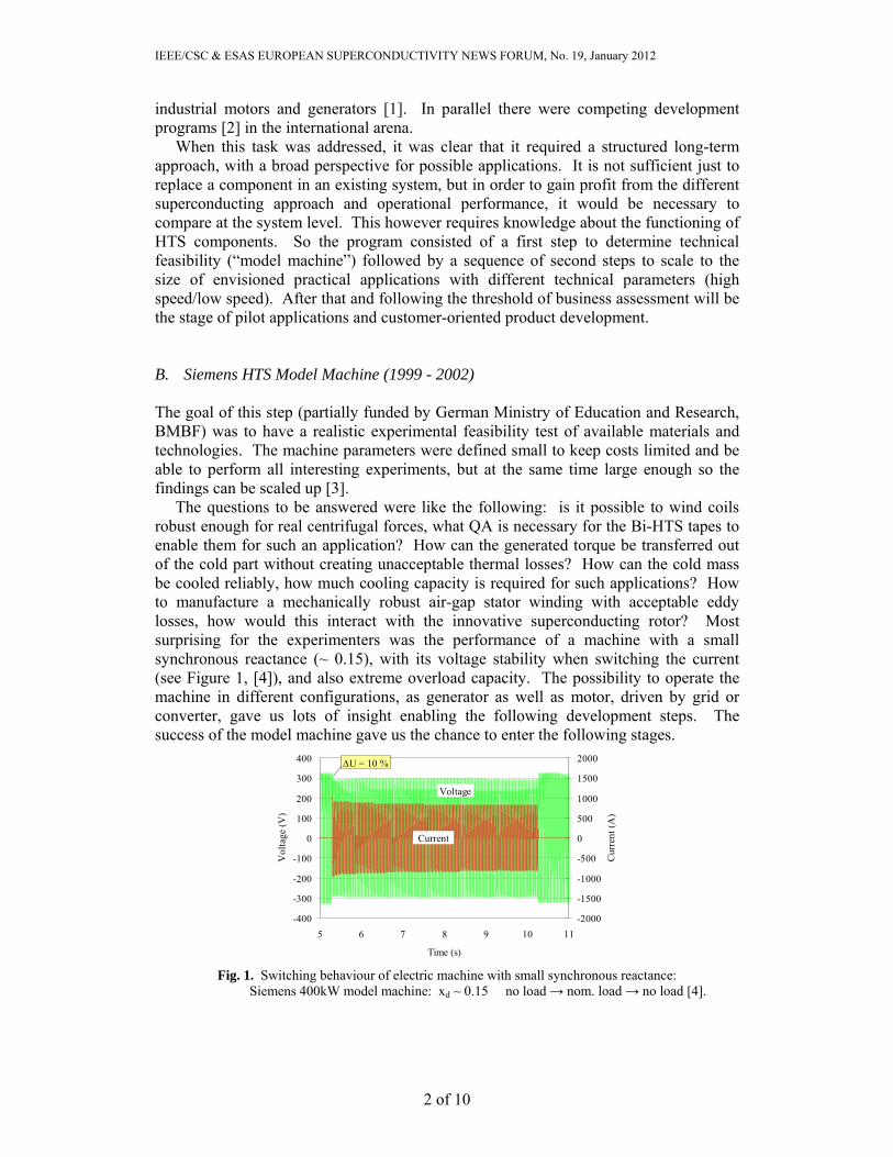
The goal of this step (partially funded by German Ministry of Education and Research, BMBF) was to have a realistic experimental feasibility test of available materials and technologies. The machine parameters were defined small to keep costs limited and be able to perform all interesting experiments, but at the same time large enough so the findings can be scaled up [3]. The questions to be answered were like the following: is it possible to wind coils robust enough for real centrifugal forces, what QA is necessary for the Bi-HTS tapes to enable them for such an application? How can the generated torque be transferred out of the cold part without creating unacceptable thermal losses? How can the cold mass be cooled reliably, how much cooling capacity is required for such applications? How to manufacture a mechanically robust air-gap stator winding with acceptable eddy losses, how would this interact with the innovative superconducting rotor? Most surprising for the experimenters was the performance of a machine with a small synchronous reactance (~ 0.15), with its voltage stability when switching the current (see Figure 1, [4]), and also extreme overload capacity. The possibility to operate the machine in different configurations, as generator as well as motor, driven by grid or converter, gave us lots of insight enabling the following development steps. The success of the model machine gave us the chance to enter the following stages.
-400
-300
-200
-100
0
100
200
300
400
5 6 7 8 9 10 11
Time (s)
Vol
tage
(V
)
-2000
-1500
-1000
-500
0
500
1000
1500
2000
Cur
rent
(A
)
Current
U = 10 %
Voltage
Fig. 1. Switching behaviour of electric machine with small synchronous reactance:
Siemens 400kW model machine: xd ~ 0.15 no load → nom. load → no load [4].
IEEE/CSC & ESAS EUROPEAN SUPERCONDUCTIVITY NEWS FORUM, No. 19, January 2012
3 of 10
C. Siemens 4MVA Superconducting Generator (2002 - 2005) The task for this project (partly funded by German Ministry of Economics, BMWi) was to drive the size of the HTS machine into realistic application range and to verify the assumed operational advantages on this scale. Of course, we tried to develop the concepts tested in the model machine. However, by designing a 2-pole machine with 3600rpm at only 4MVA we already had to deal with large centrifugal forces. The data of the machine that was tested in summer 2005 at the “Systems Test Facility” of Siemens Industry, Large Drives, Nuremberg, are presented in Table I [5]:
Table I. Data of HTS High-Speed Generator
Output kVA 4000Voltage V 6600Current A 357
p.f. - 0.8 Frequency Hz 60
Speed r.p.m. 3600 No. of poles - 2Efficiency % 98.4
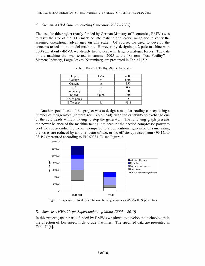
Another special task of this project was to design a modular cooling concept using a number of refrigerators (compressor + cold head), with the capability to exchange one of the cold heads without having to stop the generator. The following graph presents the power balance of the machine taking into account the needed compressor power to cool the superconducting rotor. Compared to a conventional generator of same rating the losses are reduced by about a factor of two, or the efficiency raised from ~96.1% to 98.4% (measured according to EN 60034-2), see Figure 2.
0
20000
40000
60000
80000
100000
120000
140000
1FJ4 801 HTS II
Lo
sses
(W
) Additional lossesRotor lossesStator copper lossesIron lossesFriction and windage losses
Fig 2. Comparison of total losses (conventional generator vs. 4MVA HTS generator)
D. Siemens 4MW/120rpm Superconducting Motor (2005 – 2010)
In this project (again partly funded by BMWi) we aimed to develop the technologies in the direction of low-speed, high-torque machines. The specified data are presented in Table II [6].
IEEE/CSC & ESAS EUROPEAN SUPERCONDUCTIVITY NEWS FORUM, No. 19, January 2012
4 of 10
Table II. Design Data of HTS Low-Speed, High-Torque Motor
A) nominal operation B) max. speed in field attenuation
A B Output kW 4000 4000 Voltage V 3100 3100 Current A 775 775
p.f. - 1.0 1.0 Frequency Hz 8 12.7
Speed r.p.m. 120 190 Efficiency % 96.2
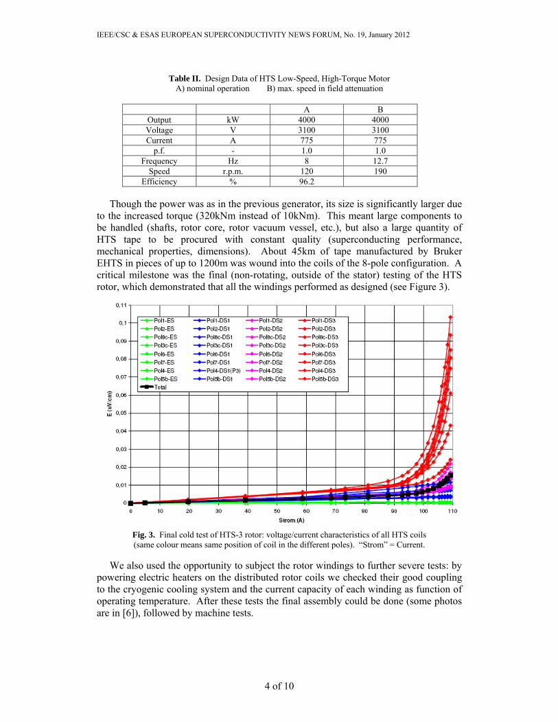
Though the power was as in the previous generator, its size is significantly larger due to the increased torque (320kNm instead of 10kNm). This meant large components to be handled (shafts, rotor core, rotor vacuum vessel, etc.), but also a large quantity of HTS tape to be procured with constant quality (superconducting performance, mechanical properties, dimensions). About 45km of tape manufactured by Bruker EHTS in pieces of up to 1200m was wound into the coils of the 8-pole configuration. A critical milestone was the final (non-rotating, outside of the stator) testing of the HTS rotor, which demonstrated that all the windings performed as designed (see Figure 3).
Fig. 3. Final cold test of HTS-3 rotor: voltage/current characteristics of all HTS coils (same colour means same position of coil in the different poles). “Strom” = Current.
We also used the opportunity to subject the rotor windings to further severe tests: by powering electric heaters on the distributed rotor coils we checked their good coupling to the cryogenic cooling system and the current capacity of each winding as function of operating temperature. After these tests the final assembly could be done (some photos are in [6]), followed by machine tests.
IEEE/CSC & ESAS EUROPEAN SUPERCONDUCTIVITY NEWS FORUM, No. 19, January 2012
5 of 10
II. TEST RESULTS FROM SIEMENS HTS-3 MACHINE
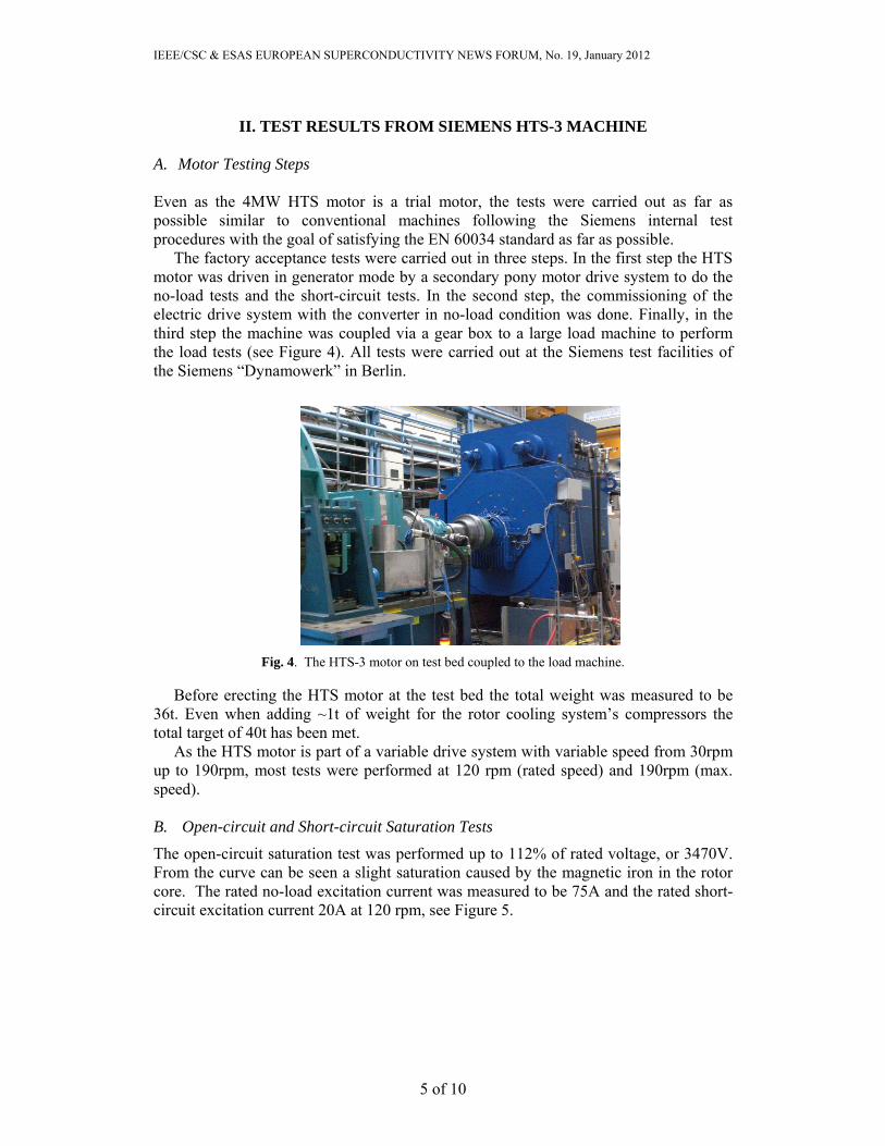
A. Motor Testing Steps Even as the 4MW HTS motor is a trial motor, the tests were carried out as far as possible similar to conventional machines following the Siemens internal test procedures with the goal of satisfying the EN 60034 standard as far as possible. The factory acceptance tests were carried out in three steps. In the first step the HTS motor was driven in generator mode by a secondary pony motor drive system to do the no-load tests and the short-circuit tests. In the second step, the commissioning of the electric drive system with the converter in no-load condition was done. Finally, in the third step the machine was coupled via a gear box to a large load machine to perform the load tests (see Figure 4). All tests were carried out at the Siemens test facilities of the Siemens “Dynamowerk” in Berlin.
Fig. 4. The HTS-3 motor on test bed coupled to the load machine. Before erecting the HTS motor at the test bed the total weight was measured to be 36t. Even when adding ~1t of weight for the rotor cooling system’s compressors the total target of 40t has been met. As the HTS motor is part of a variable drive system with variable speed from 30rpm up to 190rpm, most tests were performed at 120 rpm (rated speed) and 190rpm (max. speed). B. Open-circuit and Short-circuit Saturation Tests
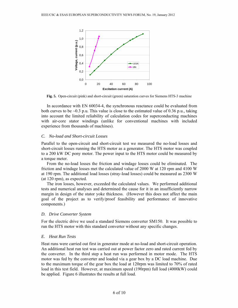
The open-circuit saturation test was performed up to 112% of rated voltage, or 3470V. From the curve can be seen a slight saturation caused by the magnetic iron in the rotor core. The rated no-load excitation current was measured to be 75A and the rated short-circuit excitation current 20A at 120 rpm, see Figure 5.
IEEE/CSC & ESAS EUROPEAN SUPERCONDUCTIVITY NEWS FORUM, No. 19, January 2012
6 of 10
0,0
0,2
0,4
0,6
0,8
1,0
1,2
0 20 40 60 80 100
Excitation current (A)
Vo
lta
ge
, cu
rre
nt
(p.u
.)
U/UN
I/IN
Fig. 5. Open-circuit (pink) and short-circuit (green) saturation curves for Siemens HTS-3 machine
In accordance with EN 60034-4, the synchronous reactance could be evaluated from both curves to be ~0.3 p.u. This value is close to the estimated value of 0.36 p.u., taking into account the limited reliability of calculation codes for superconducting machines with air-core stator windings (unlike for conventional machines with included experience from thousands of machines). C. No-load and Short-circuit Losses
Parallel to the open-circuit and short-circuit test we measured the no-load losses and short-circuit losses running the HTS motor as a generator. The HTS motor was coupled to a 200 kW DC pony motor. The power input to the HTS motor could be measured by a torque meter. From the no-load losses the friction and windage losses could be eliminated. The friction and windage losses met the calculated value of 2000 W at 120 rpm and 4100 W at 190 rpm. The additional load losses (stray-load losses) could be measured as 2300 W (at 120 rpm), as expected. The iron losses, however, exceeded the calculated values. We performed additional tests and numerical analyses and determined the cause for it in an insufficiently narrow margin in design of the stator yoke thickness. (However this does not affect the main goal of the project as to verify/proof feasibility and performance of innovative components.) D. Drive Converter System
For the electric drive we used a standard Siemens converter SM150. It was possible to run the HTS motor with this standard converter without any specific changes. E. Heat Run Tests
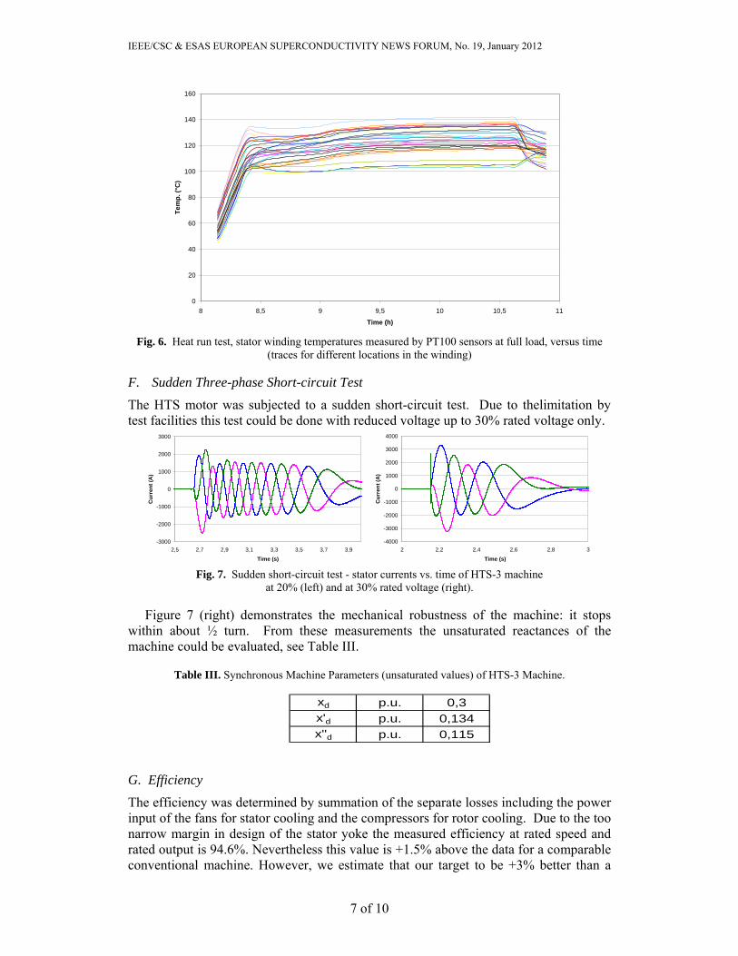
Heat runs were carried out first in generator mode at no-load and short-circuit operation. An additional heat run test was carried out at power factor zero and rated current fed by the converter. In the third step a heat run was performed in motor mode. The HTS motor was fed by the converter and loaded via a gear box by a DC load machine. Due to the maximum torque of the gear box the load at 120rpm was limited to 70% of rated load in this test field. However, at maximum speed (190rpm) full load (4000kW) could be applied. Figure 6 illustrates the results at full load.
IEEE/CSC & ESAS EUROPEAN SUPERCONDUCTIVITY NEWS FORUM, No. 19, January 2012
7 of 10
0
20
40
60
80
100
120
140
160
8 8,5 9 9,5 10 10,5 11
Time (h)
Te
mp
. (°C
)
Fig. 6. Heat run test, stator winding temperatures measured by PT100 sensors at full load, versus time
(traces for different locations in the winding) F. Sudden Three-phase Short-circuit Test
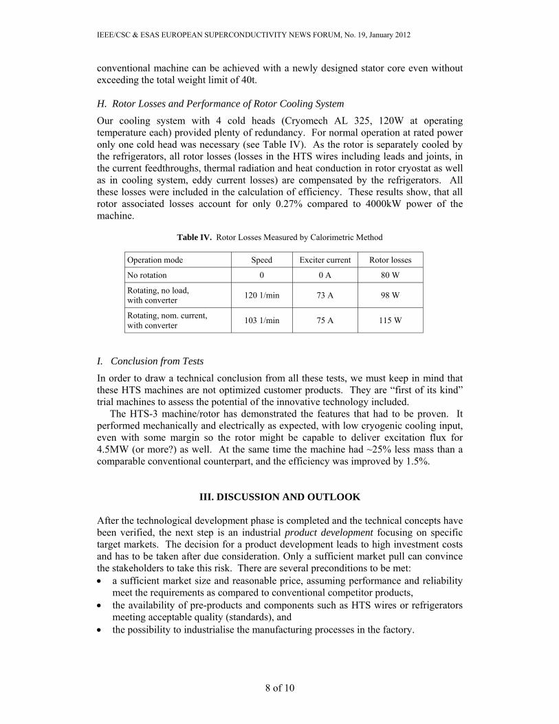
The HTS motor was subjected to a sudden short-circuit test. Due to thelimitation by test facilities this test could be done with reduced voltage up to 30% rated voltage only.
-3000
-2000
-1000
0
1000
2000
3000
2,5 2,7 2,9 3,1 3,3 3,5 3,7 3,9
Time (s)
Cu
rren
t (A
)
-4000
-3000
-2000
-1000
0
1000
2000
3000
4000
2 2,2 2,4 2,6 2,8 3
Time (s)
Cu
rren
t (A
)
Fig. 7. Sudden short-circuit test - stator currents vs. time of HTS-3 machine
at 20% (left) and at 30% rated voltage (right). Figure 7 (right) demonstrates the mechanical robustness of the machine: it stops within about ½ turn. From these measurements the unsaturated reactances of the machine could be evaluated, see Table III.
Table III. Synchronous Machine Parameters (unsaturated values) of HTS-3 Machine.
xd p.u. 0,3x'd p.u. 0,134x''d p.u. 0,115
G. Efficiency
The efficiency was determined by summation of the separate losses including the power input of the fans for stator cooling and the compressors for rotor cooling. Due to the too narrow margin in design of the stator yoke the measured efficiency at rated speed and rated output is 94.6%. Nevertheless this value is +1.5% above the data for a comparable conventional machine. However, we estimate that our target to be +3% better than a
IEEE/CSC & ESAS EUROPEAN SUPERCONDUCTIVITY NEWS FORUM, No. 19, January 2012
8 of 10
conventional machine can be achieved with a newly designed stator core even without exceeding the total weight limit of 40t. H. Rotor Losses and Performance of Rotor Cooling System
Our cooling system with 4 cold heads (Cryomech AL 325, 120W at operating temperature each) provided plenty of redundancy. For normal operation at rated power only one cold head was necessary (see Table IV). As the rotor is separately cooled by the refrigerators, all rotor losses (losses in the HTS wires including leads and joints, in the current feedthroughs, thermal radiation and heat conduction in rotor cryostat as well as in cooling system, eddy current losses) are compensated by the refrigerators. All these losses were included in the calculation of efficiency. These results show, that all rotor associated losses account for only 0.27% compared to 4000kW power of the machine.
Table IV. Rotor Losses Measured by Calorimetric Method
Operation mode Speed Exciter current Rotor losses
No rotation 0 0 A 80 W
Rotating, no load, with converter
120 1/min 73 A 98 W
Rotating, nom. current, with converter
103 1/min 75 A 115 W
I. Conclusion from Tests
In order to draw a technical conclusion from all these tests, we must keep in mind that these HTS machines are not optimized customer products. They are “first of its kind” trial machines to assess the potential of the innovative technology included. The HTS-3 machine/rotor has demonstrated the features that had to be proven. It performed mechanically and electrically as expected, with low cryogenic cooling input, even with some margin so the rotor might be capable to deliver excitation flux for 4.5MW (or more?) as well. At the same time the machine had ~25% less mass than a comparable conventional counterpart, and the efficiency was improved by 1.5%.
III. DISCUSSION AND OUTLOOK
After the technological development phase is completed and the technical concepts have been verified, the next step is an industrial product development focusing on specific target markets. The decision for a product development leads to high investment costs and has to be taken after due consideration. Only a sufficient market pull can convince the stakeholders to take this risk. There are several preconditions to be met: a sufficient market size and reasonable price, assuming performance and reliability
meet the requirements as compared to conventional competitor products, the availability of pre-products and components such as HTS wires or refrigerators
meeting acceptable quality (standards), and the possibility to industrialise the manufacturing processes in the factory.
IEEE/CSC & ESAS EUROPEAN SUPERCONDUCTIVITY NEWS FORUM, No. 19, January 2012
9 of 10
Due to the not yet industrialised manufacturing processes, the HTS products lose in a one-by-one price comparison. However, the HTS machines promise a number of additional advantageous features. The question is: are these advantages worth the price on the market and are the customers willing to pay that price? Today, an increased efficiency alone cannot be the argument to shift from conventional to HTS drive systems in most applications. Energy prices are still too low and even regulations to reduce the environmental impact will not compensate for the higher cost of the young HTS machine technology (even if we take into account that the performance of superconductors and refrigerators are improving and the specific costs are decreasing). We should not forget, HTS machines are “just synchronous machines” from this point of view, and must compete with an established technology more than 100 years old, cost-efficient, proven and optimized in millions of operating hours. Of course, from a superconductivity expert’s point of view such an HTS machine is not just a synchronous machine, but a machine with improved efficiency, smaller size, and high stiffness at the same time. It is this combination of features that makes the HTS machine unique. In order to benefit from that fact it is important to regard the whole system and not only the component itself [7]. Such a perspective still makes the replacement of single conventional machines by HTS models difficult, but it provides a lot of potential for the future – assuming the specific benefits of HTS machines fit into the chosen application. That might be the case in advanced ship design, to give just one example: Usually, to fulfil the ship’s duties a shipyard has to guarantee a specific range at a defined speed to its customer, the prospective ship owner. Large ships burn hundreds of kg or even tons of marine fuel per hour and have to be operated independently from supply for hundreds of hours. With an increased efficiency, the ship’s bunker volume and the weight of marine fuel can be reduced by several tons. Combined with lightweight HTS machinery, a noteworthy reduction of the ship weight can be achieved, which can be used in several ways: Additional payload or equipment installed to add functionality. Reduced draft (as long as stability is given), as a simple means to reduce the drag
and thus reducing the propulsion power needed for a given speed, burning even less fuel. The impact from weight reduction on fuel consumption can be even higher than the direct impact of the increased efficiency of HTS machines!
A new ship concept, e.g., hull design to decrease drag and fuel consumption even more. Here, HTS machines can really be an enabling technology. A hull designer has to take care of a lot more of requirements than Archimedes’ principle. Stability and manoeuvrability have to be considered for every loading and under all environmental conditions on the seas. For that, weight has to be balanced carefully, the placement of large and heavy components like propulsion motors or diesel-generator sets suffers from many restrictions. Not only due to their lower volume and weight, but also because of further important features like reduced shaft height, HTS machines give the ship designer new degrees of freedom.
Of course, tying the future of HTS technology to improved performance of such advanced systems also means that very high standards for performance and reliability have to be accepted as reference. For example, if one of the arguments is improved efficiency, the reliability of the HTS system including cryogenics must be extremely high, as short periods of non-availability would directly destroy any efficiency advantage. However, technical reliability and capability to operate for long periods
IEEE/CSC & ESAS EUROPEAN SUPERCONDUCTIVITY NEWS FORUM, No. 19, January 2012
10 of 10
without maintenance have to be developed – these are part of a product development agenda. They can only be achieved on the base of experience, and not just in the test-bed for a testing over a few weeks, but in the real application field. So pilot projects are necessary to learn in all practical detail and at the same time collect know-how to convince potential future customers. We performed a first step in this direction by operating the HTS-2 generator for two years in various long-term test configurations in the Siemens facilities at Nuremberg for reactive power compensation, but we are aware that much more of this kind of experience will be required, especially experience closer to the real application field. The other argument is often, that HTS technology is too expensive. That seems difficult to counter today, as we know conventional Cu technology has seen cost-down for a century. But we think the argument is premature. Of course it is necessary that there is economic potential for the innovative technologies to become competitive. For example, looking at 2G-HTS this should be the case. What is needed most at this stage is operational experience; in parallel to gaining it, optimizing developments can be performed in all relevant fields: in-house with regard to the manufacturing path, and also on the suppliers’ side, from HTS conductors to cryogenics. These activities are going on, as is documented in other presentations at this conference, and in parallel with growing operational experience from pilot projects this will continuously strengthen the case for reliable HTS machine applications in the future. With this perspective, HTS technology can indeed be seen as a key for a sustainable future that has to economize materials and use valuable electric power in the most efficient way.
REFERENCES [1] G. Bogner, The development of large superconducting D.C. magnet in Europe – present and future applications, Proceedings ASC 1972, pp. 214-225. [2] G. Papst, B.B. Gamble, A.J. Rodenbush, R. Schottler, Development of synchronous motors and generators with field windings, Proceedings EuCAS 1997, and B. Gamble, G. Snitchler, T. MacDonald, Full power test of a 36.5 MW HTS propulsion motor, IEEE Trans. Appl. Supercond 21, 1083-88 (2011). [3] W. Nick, G. Nerowski, H.-W. Neumüller, et al, 380 kW synchronous motor with HTS rotor windings – development at Siemens and first test results, Physica C 372-376 1506-1512 (2002). [4] J. Frauenhofer, M. Kaufhold, P. Kummeth, G. Nerowski, W. Nick: High-Temperature-Superconducting Machines – A High-Technology Step for Large Rotating Electric Machines, Proceedings of SPEEDAM 2006 Symposium (Taormina). [5] W. Nick, M. Frank, G. Klaus, J. Frauenhofer, H.-W. Neumüller, “Operational Experience with the World’s First 3600 rpm 4MVA HTS Generator”, IEEE Trans. Appl Supercond. 17 2030-2033 (2007). [6] W. Nick, M. Frank, P. Kummeth, et al, Development and Construction of an HTS Rotor for Ship Propulsion Application, Proceedings EuCAS 2009, Dresden, IOP Conf. Proc. 234, no 3, 986-994 (2010). [7] J. Grundmann, R. Hartig, K. Kahlen, et al., Superconducting motors, generators and fault current limiters – key components for novel AES concepts, Proceedings AES 2007 (all-electric ship conference), London, September 25 - 26, 2007.