Test System Architecture for AOCS Testing Test System Architecture for AOCS Testing S Sudhakar-Group Head, CDEG,ISAC/ISRO Email: [email protected]FSW-2015 John Hopkins Applied Physics Lab,Maryland, USA October 2015
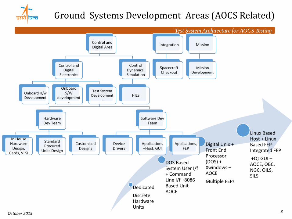
DOS Based System User I/f + Command Line I/f +8086 Based Unit- AOCE
Digital Unix + Front End Processor (DOS) + Xwindows – AOCE
Multiple FEPs
Linux Based Host + Linux Based FEP-Integrated FEP
+Qt GUI – AOCE, OBC, NGC, OILS, SILS
Control and Digital Area
Control and Digital
Electronics
Onboard H/w Development
Onboard S/W
development -
Test System Development
-
Hardware Dev Team
In House Hardware
Design, Cards, VLSI
Standard Procured
Units Design
Customised Designs
Software Dev Team
Device Drivers
Applications –Host, GUI
Applications, FEP
Control Dynamics, Simulation
HILS
Integration
Spacecraft Checkout
Mission
Mission Development
Ground Systems Development Areas (AOCS Related)
Test System Architecture for AOCS Testing
October 2015 4
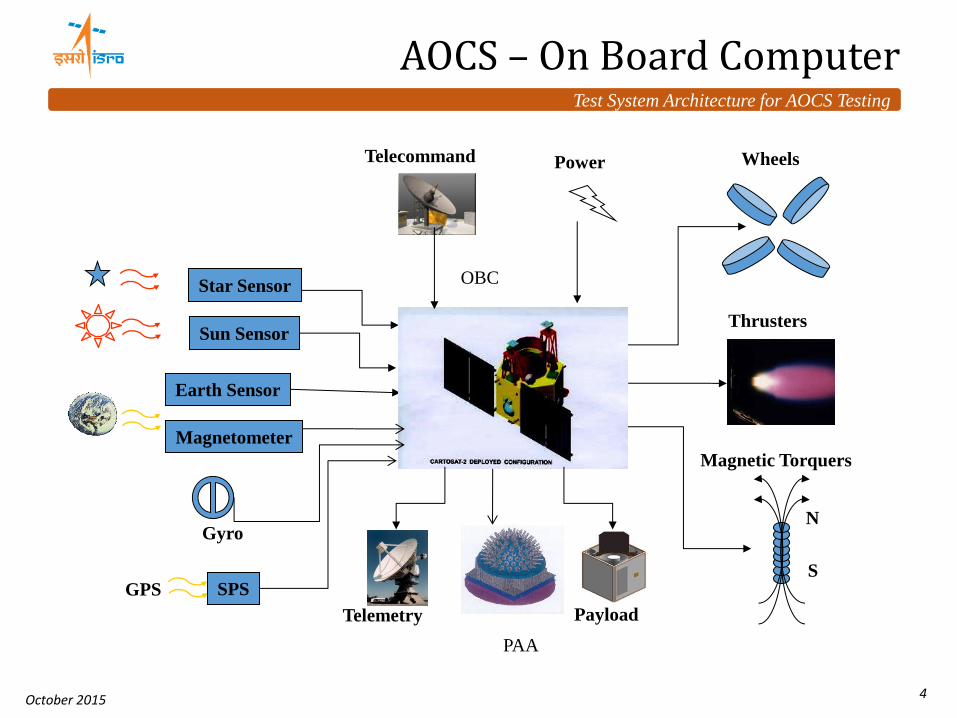
AOCS – On Board Computer
Earth Sensor
Gyro
Wheels
Thrusters
S
N
Magnetic Torquers
Star Sensor
PAA
Magnetometer
GPS SPS
Payload
Power Telecommand
OBC
Telemetry
Sun Sensor
Test System Architecture for AOCS Testing
October 2015 5
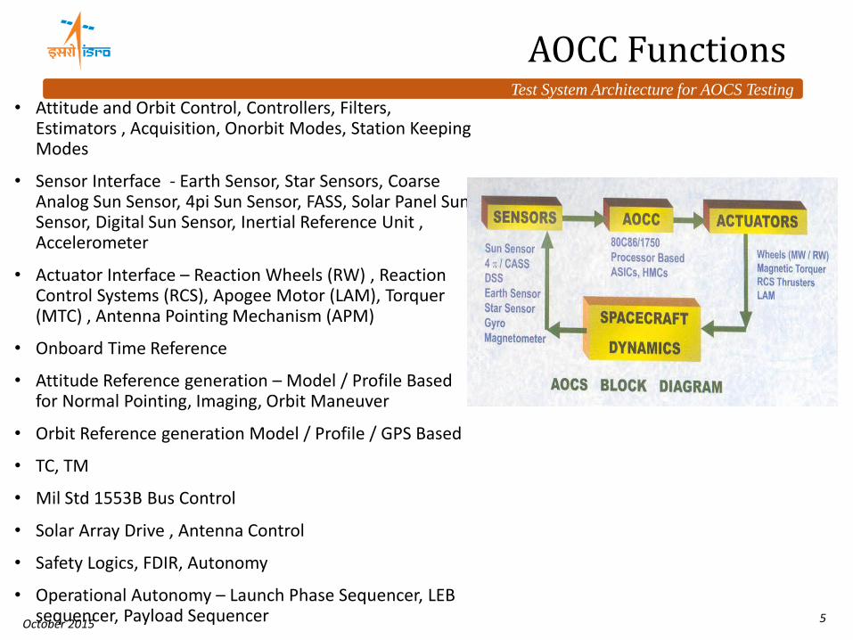
AOCC Functions
• Attitude and Orbit Control, Controllers, Filters, Estimators , Acquisition, Onorbit Modes, Station Keeping Modes
• Sensor Interface - Earth Sensor, Star Sensors, Coarse Analog Sun Sensor, 4pi Sun Sensor, FASS, Solar Panel Sun Sensor, Digital Sun Sensor, Inertial Reference Unit , Accelerometer
• Actuator Interface – Reaction Wheels (RW) , Reaction Control Systems (RCS), Apogee Motor (LAM), Torquer (MTC) , Antenna Pointing Mechanism (APM)
• Onboard Time Reference
• Attitude Reference generation – Model / Profile Based for Normal Pointing, Imaging, Orbit Maneuver
• Orbit Reference generation Model / Profile / GPS Based
• Closed Loop Dynamic Tests – On Board Computer In loop simulation (OILS) Tests
• Mission Scenario Tests
• Environmental Tests
• Operational Validation Tests
Without Test System
• HILS- Hardware In Loop Simulation Tests
• Integrated Spacecraft Tests
Test System Architecture for AOCS Testing
October 2015 7
Ground Test System Design
Test System Provides
All Electrical I/f, Power I/f, Loads
Multi RT Simulator + Bus Monitor (1553)
Electrical Stimuli + Measurements
Instruments
Supports Open Loop /Closed loop Testing
Interface verification
Timing Verification
OBC/AOCC Simulators for prototype or i/f testing of other subsystems
Software for
Interface Simulation
Sensor, Actuator Models
Orbit Model, Sun Model
Dynamics Simulation
Automatic Testing
GUI, RT Plot, Display, Data Logging and Retrieval
Mil 1553 Bus Monitor
Front End Processor
System Under Test
Host
Located Near SUT - AOCC
Linux Based RT – With PCI based Add on
cards + Hardware
Linux Based Host
• Distributed Architecture • Host System – Data Processing, User Interface, Simulation • FEP ( Front End Processor) System – Data Acquisition, System Interface • Dedicated Ethernet Interface
Test System Architecture for AOCS Testing
October 2015 8
Ground Test System Elements
Test System Architecture for AOCS Testing
October 2015 9
Typical Test System Architecture
Test System Architecture for AOCS Testing
October 2015 10
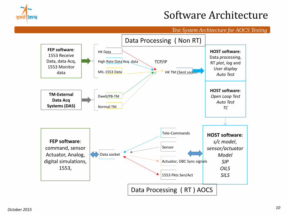
Software Architecture
TCP/IP
FEP software: 1553 Receive
Data, data Acq, 1553 Monitor
data
TM-External Data Acq
Systems (DAS)
HK Data
High Rate Data Acq data
MIL-1553 Data
HOST software: Data processing, RT plot, log and
User display Auto Test
HK TM Client socket
Dwell/PB-TM
Normal-TM
FEP software: command, sensor Actuator, Analog,
digital simulations, 1553,
HOST software: s/c model,
sensor/actuator Model
SIP OILS SILS
Tele-Commands
Sensor
Actuator, OBC Sync signals
1553 Pkts Sen/Act
Data socket
Data Processing ( Non RT)
Data Processing ( RT ) AOCS
HOST software: Open Loop Test
Auto Test TC
Test System Architecture for AOCS Testing
October 2015 11
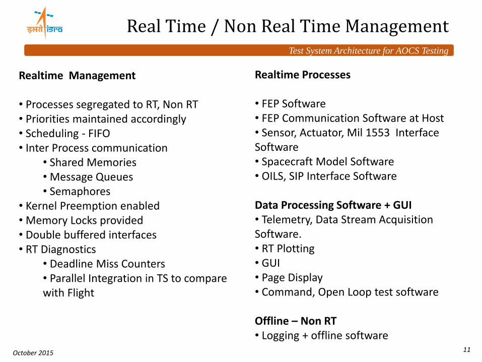
Realtime Management • Processes segregated to RT, Non RT • Priorities maintained accordingly • Scheduling - FIFO • Inter Process communication
• Deadline Miss Counters • Parallel Integration in TS to compare with Flight
Realtime Processes • FEP Software • FEP Communication Software at Host • Sensor, Actuator, Mil 1553 Interface Software • Spacecraft Model Software • OILS, SIP Interface Software Data Processing Software + GUI • Telemetry, Data Stream Acquisition Software. • RT Plotting • GUI • Page Display • Command, Open Loop test software Offline – Non RT • Logging + offline software
Real Time / Non Real Time Management
Test System Architecture for AOCS Testing
October 2015 12
Different Processes Organisation – For open loop
Data Process
ing
DAS Data
Data Log
User
Open Loop
Test I/F GUI
TC Process
ing
Sensor Actuato
r I/f
Spacecraft
Model
FEP System Under
Test
RT Plotting
, Utiities
Open Loop Test
Sensor Stimuli
Telecommand
Test System Settings
Mil 1553B Stimuli, Bus
Handling
Instruments
Dynamics, Initial
Conditions Settings
Open Loop Static Tests: • All Logical Tests for Sensor Inputs and Actuator Outputs • Performance of AOCS – Gains verification • Open Loop AOCS mode Test Vector reading, processing, Verification • Sync with Onboard wherever required.
Test System Architecture for AOCS Testing
October 2015 13
SIP Software
Buf1
Buf 2
Data Files Test System Software
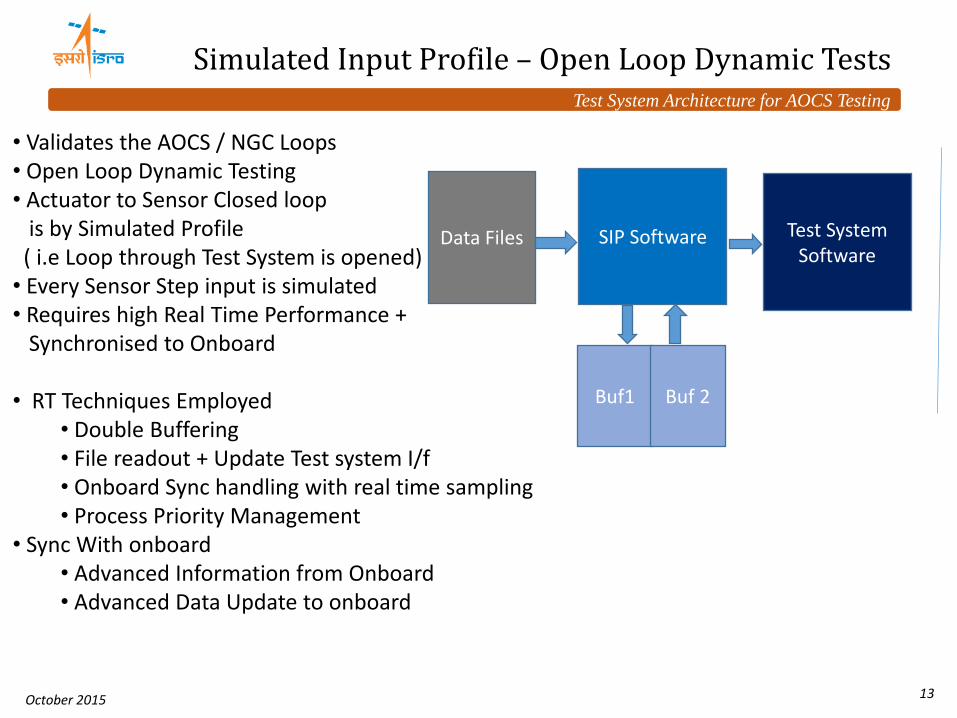
Simulated Input Profile – Open Loop Dynamic Tests
• Validates the AOCS / NGC Loops • Open Loop Dynamic Testing • Actuator to Sensor Closed loop is by Simulated Profile ( i.e Loop through Test System is opened) • Every Sensor Step input is simulated • Requires high Real Time Performance + Synchronised to Onboard • RT Techniques Employed
• Double Buffering • File readout + Update Test system I/f • Onboard Sync handling with real time sampling • Process Priority Management
• Sync With onboard • Advanced Information from Onboard • Advanced Data Update to onboard
Test System Architecture for AOCS Testing
October 2015 14
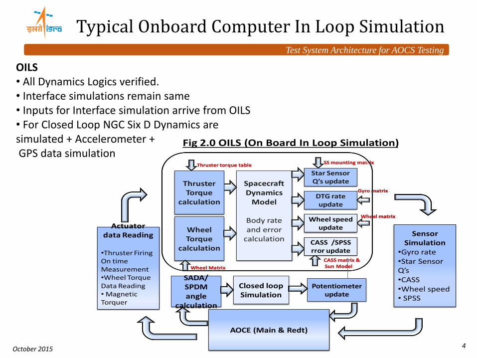
Fig 2.0 OILS (On Board In Loop Simulation)
Actuator data Reading
•Thruster Firing On time Measurement•Wheel TachoData Reading
OILS • All Dynamics Logics verified. • Interface simulations remain same • Inputs for Interface simulation arrive from OILS • For Closed Loop NGC Six D Dynamics are simulated + Accelerometer + GPS data simulation
Test System Architecture for AOCS Testing
October 2015 15
Data Scheduling & Synchronisation
DAS s/w FEP
AOCS Reads Gyro
DAS s/w FEP
Sensor I/f S/w Host
Actuator I/f
S/w Host
Sensor Model
Actuator Model
Open Loop
SIP
OILS
Spacecraft Model
Interface Process
FEP Data Acq
Sync Cycles 8ms
Sensor Data Update
Actuator Data Read
Y,R,P
Torque
Sensor I/F
Actuator I/F
Data I/F
Data I/F
AOCS Data I/F
Synchronisation Processes Involved: • Async / Sync Mode • Synchronisation with Onboard • Sync with respect to Signal – • Parallel Accumulation / Integration • Simulation runs at higher Resolution – say 2ms • Integration cycle is submultiple of onboard clock – To ensure proper Integration & transfer of data wherever required.
Test System Architecture for AOCS Testing
October 2015 16
Interface Simulation Software -Sensors
Sensors / Any Input Stimuli • e.g. Star Sensor, Battery Current, Solar Array Drive Pos • OO Based approach • Component - Database Driven
• Component Data Base – Describes Types Earth Sensor / Star sensor • Project Database – Objects from above components – Declared – Each instance of sensor + other Info
• Shared Memory for Interface Level inputs • User Input / OILS / SILS Input
• Inputs for FDIR Simulation • FDIR at Interface Level simulation
• Output for • FEP communication Interface
ES Sen1
ES
Stimuli I/f
Processing
Sensor Model
Commn I/f
FEP Open loop/ OILS/SIP
Components
Sen4 SS
Project Databases Instances
Test System Architecture for AOCS Testing
October 2015 17
Interface Simulation Software -Actuators
Actuator / Any Output • e.g. Reaction Wheel, Torquer, Thruster , Solar Array Drive, Antenna Control
• OO Based approach •Component based - Database Driven
• Component Data Base – Describes Types Wheel, Thruster • Project Database – Objects from above components – Each instance of Actuator + Other Info
• Shared Memory for Interface Level inputs • Output to OILS • Inputs for FDIR Simulation
• Failure simulation for Actuators • Output for
• Actuator Model
RW Act1 =RW
Actuator I/f
Processing
Actuator Model
Commn I/f
FEP
Open loop/ OILS/SIP
To Stimuli
Act5 =MT
C
Components Project Database Instances
Test System Architecture for AOCS Testing
October 2015 18
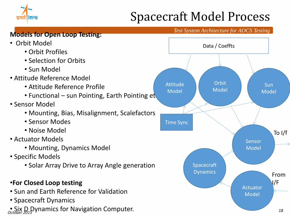
Spacecraft Model Process Models for Open Loop Testing: • Orbit Model
• Orbit Profiles • Selection for Orbits • Sun Model
• Attitude Reference Model • Attitude Reference Profile • Functional – sun Pointing, Earth Pointing etc
• Sensor Model • Mounting, Bias, Misalignment, Scalefactors • Sensor Modes • Noise Model
• Actuator Models • Mounting, Dynamics Model
• Specific Models • Solar Array Drive to Array Angle generation
•For Closed Loop testing • Sun and Earth Reference for Validation • Spacecraft Dynamics • Six D Dynamics for Navigation Computer.
Attitude Model
Orbit Model
Sun Model
Spacecraft Dynamics
Sensor Model
Actuator Model
From I/F
To I/f
Data / Coeffts
Time Sync
Test System Architecture for AOCS Testing
October 2015 19
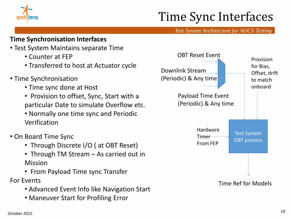
Time Sync Interfaces
Time Synchronisation Interfaces • Test System Maintains separate Time
• Counter at FEP • Transferred to host at Actuator cycle
• Time Synchronisation • Time sync done at Host • Provision to offset, Sync, Start with a particular Date to simulate Overflow etc. • Normally one time sync and Periodic Verification
• On Board Time Sync • Through Discrete I/O ( at OBT Reset) • Through TM Stream – As carried out in Mission • From Payload Time sync Transfer
For Events • Advanced Event Info like Navigation Start • Maneuver Start for Profiling Error
OBT Reset Event
Payload Time Event (Periodic) & Any time
Downlink Stream (Periodic) & Any time
Test System OBT process
Hardware Timer From FEP
Provision for Bias, Offset, drift to match onboard
Time Ref for Models
Test System Architecture for AOCS Testing
October 2015 20
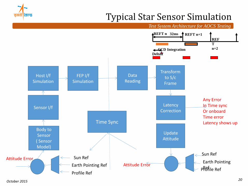
Typical Star Sensor Simulation
Profile Ref Profile Ref
Data Reading
Transform to S/c Frame
Latency Correction
Update Attitude
Sun Ref
Earth Pointing Ref
FEP I/f Simulation
Host I/f Simulation
Body to Sensor
( Sensor Model)
Sensor I/f
Sun Ref
Earth Pointing Ref Attitude Error
Attitude Error
Time Sync
32ms REFT n REFT n+1
REF
T
n+2 CCD Integration
Delta t
Any Error In Time sync Or onboard Time error Latency shows up
Test System Architecture for AOCS Testing
October 2015 21
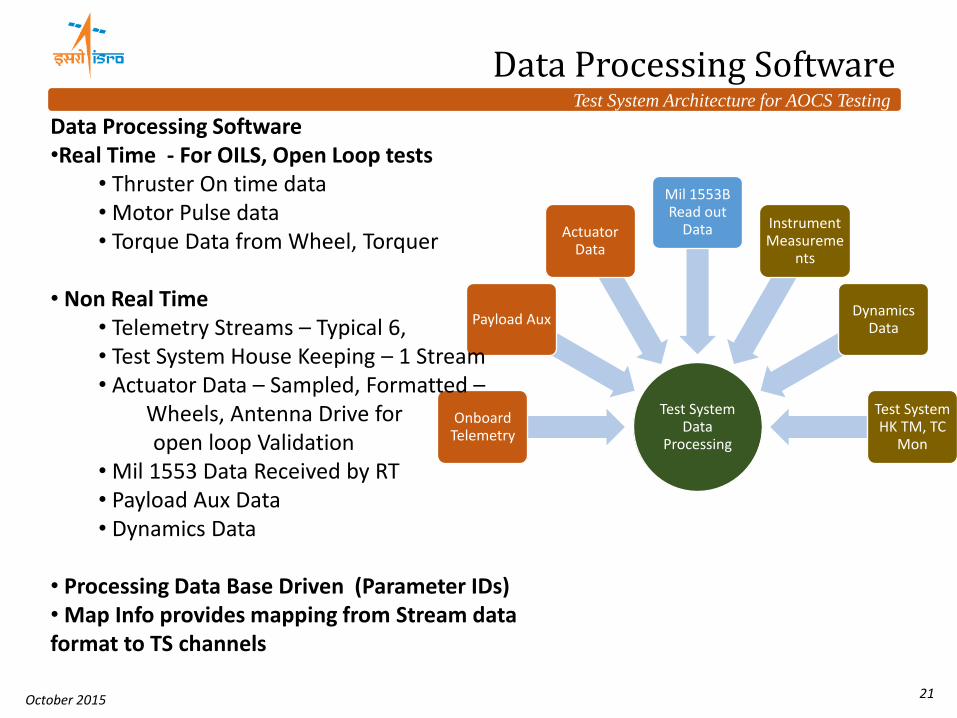
Test System Data
Processing
Onboard Telemetry
Payload Aux
Actuator Data
Mil 1553B Read out
Data Instrument Measureme
nts
Dynamics Data
Test System HK TM, TC
Mon
Data Processing Software •Real Time - For OILS, Open Loop tests
• Thruster On time data • Motor Pulse data • Torque Data from Wheel, Torquer
• Non Real Time
• Telemetry Streams – Typical 6, • Test System House Keeping – 1 Stream • Actuator Data – Sampled, Formatted – Wheels, Antenna Drive for open loop Validation • Mil 1553 Data Received by RT • Payload Aux Data • Dynamics Data
• Processing Data Base Driven (Parameter IDs) • Map Info provides mapping from Stream data format to TS channels
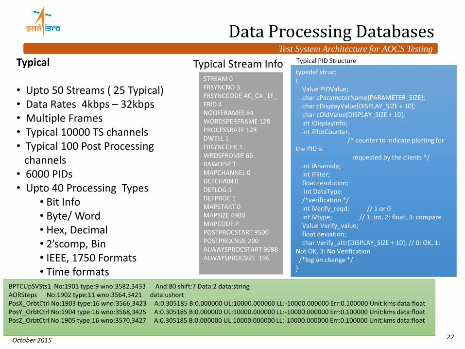
Typical Stream Info typedef struct { Value PIDValue; char cParameterName[PARAMETER_SIZE]; char cDisplayValue[DISPLAY_SIZE + 10]; char cOldValue[DISPLAY_SIZE + 10]; int iDisplayInfo; int iPlotCounter; /* counter to indicate plotting for the PID is requested by the clients */ int iAnamoly; int iFilter; float resolution; int DataType; /*verification */ int iVerify_reqd; // 1 or 0 int iVtype; // 1: int, 2: float, 3: compare Value Verify_value; float deviation; char Verify_attr[DISPLAY_SIZE + 10]; // 0: OK, 1: Not OK, 3: No Verification /*log on change */ }
Typical PID Structure
Test System Architecture for AOCS Testing
October 2015 23
Typical Data Processing Software
Initialisation • Read Data Bases PID Data, Map Data, Stream Info • Create Linked Lists, Cross Ref Lists
• On Receiving Stream Data • Log the Stream Data • For Every Sub Block of Stream Data
• Map the Stream Data to TS Channels • For Each TS Channel Updated
• Process all Affected PIDs • For all the Post Processing TS Channels Updated
•Process all Affected PIDs • Update the PID Data for all the Logging Plotting Utilities through Queue
( RT Plotting, Anomaly, Automatic Testing inputs)
Stream 1
Map 1
PID Linked List TS Channels
Stream 2 Stream 3
Stream n
Map 2
Map 3
Map n
Post Processing Updates
Test System Architecture for AOCS Testing
October 2015 24
Front End Processor Software
Device Drivers • Mil 1553B Multi RT Simulator • TC Encoder • ISR 1ms •Data Acquisition Driver Analog, Digital • Functions for Sync Mode with SUT / Non Sync Mode
• Applications • Host – FEP Communication 1 • Mil 1553 B Handling and Host Communication 2
• For Real Time Data • For Stream Data ( Non RT)
• Mil 1553 Bus Monitor • Instruments Readout
• Power Supply, Current Meters
1553 FEP
1553 Host
Real Time
Data Proces
sing Softwr
awe
Non 1553
I/f
Non 1553 Host
1553 Device Driver
1553 Bus
Monitor
Hardware
Device Driver
Test System Architecture for AOCS Testing
October 2015 25
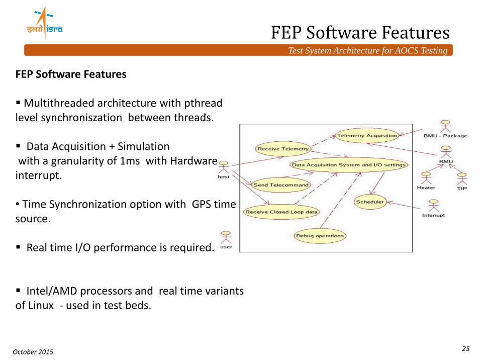
FEP Software Features Multithreaded architecture with pthread level synchroniszation between threads. Data Acquisition + Simulation with a granularity of 1ms with Hardware interrupt. • Time Synchronization option with GPS time source.
Real time I/O performance is required.
Intel/AMD processors and real time variants of Linux - used in test beds.
FEP Software Features
Test System Architecture for AOCS Testing
October 2015 26
Testing FDIR Logics
FDIR Logics • Requirements for providing all Interfaces for FDIR • Nominal and Non Nominal Simulations • Negative checks verification • Verification of Time checks – require synchronised Real time simulation. ( Carried out in the lines of SIP mode) • Event Handling - Time line to be simulated in TS
( To simulate exact action) • Interface Level failures simulation
• Checksum errors • Latency Errors Simulation
• Complex with Multiple Buffers
Error Simulation -Ve checks
Error Simulation +Ve checks
On Board Cycle and TS cycle synchronised For simulations
Test System Architecture for AOCS Testing
October 2015 27
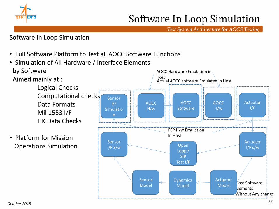
Software In Loop Simulation
Host Software Elements Without Any change
Actuator I/F
Dynamics Model
Sensor I/F
Simulation
AOCC H/w
Sensor I/F S/w
Sensor Model
Actuator I/F s/w
Actuator Model
AOCC Software
AOCC H/w
Actual AOCC software Emulated in Host
FEP H/w Emulation In Host
Open Loop /
SIP Test I/F
AOCC Hardware Emulation in Host
Software In Loop Simulation • Full Software Platform to Test all AOCC Software Functions • Simulation of All Hardware / Interface Elements by Software Aimed mainly at : Logical Checks Computational checks Data Formats Mil 1553 I/F HK Data Checks • Platform for Mission Operations Simulation
Test System Architecture for AOCS Testing
October 2015 28
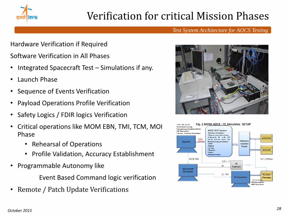
Verification for critical Mission Phases
Hardware Verification if Required
Software Verification in All Phases
• Integrated Spacecraft Test – Simulations if any.
• Launch Phase
• Sequence of Events Verification
• Payload Operations Profile Verification
• Safety Logics / FDIR logics Verification
• Critical operations like MOM EBN, TMI, TCM, MOI Phase
• Rehearsal of Operations
• Profile Validation, Accuracy Establishment
• Programmable Autonomy like
Event Based Command logic verification
• Remote / Patch Update Verifications
Test System Architecture for AOCS Testing
October 2015 29
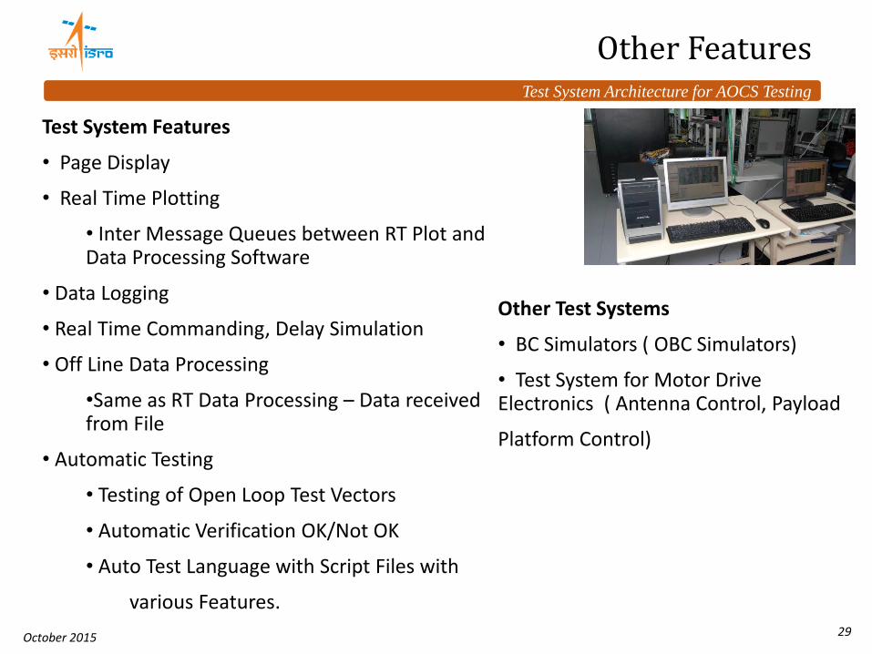
Other Features
Test System Features
• Page Display
• Real Time Plotting
• Inter Message Queues between RT Plot and Data Processing Software
• Data Logging
• Real Time Commanding, Delay Simulation
• Off Line Data Processing
•Same as RT Data Processing – Data received from File
• Automatic Testing
• Testing of Open Loop Test Vectors
• Automatic Verification OK/Not OK
• Auto Test Language with Script Files with
various Features.
Other Test Systems
• BC Simulators ( OBC Simulators)
• Test System for Motor Drive Electronics ( Antenna Control, Payload
Platform Control)
Test System Architecture for AOCS Testing
October 2015 30
Major causes of Error in Testing / Simulation
Test Level
• Simulation Assumptions / Actual Information not available
• Time Synchronisation Errors
• Scenario / Sequence Coverage
• Accuracy, Precision, Sampling Simulation Errors
• Test coverage is not complete/insufficient test cases
• Actuator I/f clearance with Diagnostic TM rather than actual actuator output.
• Insufficient Test – especially less critical ones like TM
Identification of simulation limitations and addressing alternate methods of validation
Analysis, Review and Process Implementation
Test case generation from requirements /Test Review Boards/Test procedure review/ Automation of testing / Test Results Review
Observations tracking and guidelines/check list generations
Test System Architecture for AOCS Testing
October 2015 31
Summary & Future Enhancements.
• The Distributed Test System Architecture has been used extensively for AOCS, Integrated OBC, NGC applications
• With little modifications, same frame work is being used for HILS.
• Continuous improvements in terms of Automation, Simulations, Data Presentations, Validations are being done.
• Increased real time performance, Inclusion of Flexibility dynamics for Closed loop simulation & higher models - the requirements for AOCS are being continuously improved / added.
• Software In Loop simulation – being developed for Testing, Operational requirements. Hardware Modelling is also being attempted.
• Standard Auto Test Languages, Databases are to be explored.
• Miniaturisation in Hardware is being attempted.
Test System Architecture for AOCS Testing
October 2015 32
Acknowledgements are Due to • Dr. A S Kiran Kumar, Chairman ISRO • Dr. M Annadurai, Director ISAC • Mr. Subramanya Udupa, DD, CDA, ISAC • Colleagues and Team members of Control and Digital Electronics Group, Sincere thanks to •Dr. Allen D Unell, Chairman FSW-2015 • Mr. Subodh Harmalkar, FSW-2015, APL