1 TestBencher Pro Graphical Test Bench Generation for VHDL, Verilog, and C++! Today's presentation will cover TestBencher Pro, a VHDL, Verilog, and C++ test bench generator that dramatically reduces the time required to create and maintain test benches. One of the most time consuming tasks for users of HDL languages is coding test benches to verify the operation of their design. In his book "Writing Testbenches," Janick Bergeron estimates that 70% of design time is spent verifying HDL code models and that the test bench makes up 80% of the total HDL code generated during product development. TestBencher Pro automates the most tedious aspects of test bench development, allowing you to focus on the design and operation of the test bench. This is accomplished by representing each bus transaction graphically and then automatically generating the code for each transaction. TestBencher makes use of the powerful features of the language that is being generated and the engineer does not have to hand-code each transaction. When hand coding, the designer would have to take the time to deal with the specifics of the design (port information, monitoring system response, etc) as well as common programming errors (race conditions, minor logic errors, and code design problems). This removes a considerable amount of time from the test bench design process because TestBencher manages the low-level details and automatically generates a valid test bench.
Transcript
1
TestBencher Pro
Graphical Test Bench Generation for VHDL, Verilog, and C++!
Today's presentation will cover TestBencher Pro, a VHDL, Verilog, and C++ test bench generator that dramatically reduces the time required to create and maintain test benches.
One of the most time consuming tasks for users of HDL languages is coding test benches to verify the operation of their design. In his book "Writing Testbenches," Janick Bergeron estimates that 70% of design time is spent verifying HDL code models and that the test bench makes up 80% of the total HDL code generated during product development.
TestBencher Pro automates the most tedious aspects of test benchdevelopment, allowing you to focus on the design and operation of the test bench. This is accomplished by representing each bus transaction graphically and then automatically generating the code for each transaction. TestBencher makes use of the powerful features of the language that is being generated and the engineer does not have to hand-code each transaction. When hand coding, the designer would have to take the time to deal with the specifics of the design (port information, monitoring system response, etc) as well as common programming errors (race conditions, minor logic errors, and code design problems). This removes a considerable amount of time from the test bench design process because TestBencher manages the low-level details and automatically generates a valid test bench.
2
1.0 TestBencher Pro Overview• Provides specification based verification• Generates VHDL, Verilog, and C++ bus-functional models
and test benches from graphical timing diagrams
• Resulting code is modular, easy to debug, and compatible with all major VHDL and Verilog simulators
• Language independent timing diagrams enhance the ability of engineers to share data across projects
• The graphical interface speeds development for both expert and novice users, dramatically reducing the time necessary to create and maintain test benches
TestBencher represents a radical breakthrough in the automated development of HDL test benches. TestBencher Pro provides designers with a graphical environment for rapidly generating system level test benches. Users draw timing diagrams and TestBencher generates native VHDL, Verilog, and C++ code. The resulting code is modular and can be used with all major VHDL and Verilog simulators. TestBencher Pro's graphical interface speeds up test bench development for both expert and novice users. TestBencher generates all of the low-level transaction code, verification code, sequence detection, error reporting and file I/O code. The graphical representation also enhances the ability of engineers to share data across projects, even though new engineers might not be familiar with the details of the test bench design.
3
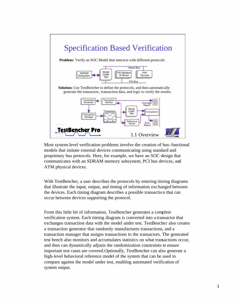
Specification Based VerificationProblem: Verify an SOC Model that interacts with different protocols
Solution: Use TestBencher to define the protocols, and then automaticallygenerate the transactors , transaction data, and logic to verify the results.
1.1 Overview
Most system-level verification problems involve the creation of bus-functional models that imitate external devices communicating using standard and proprietary bus protocols. Here, for example, we have an SOC design that communicates with an SDRAM memory subsystem, PCI bus devices, and ATM physical devices.
With TestBencher, a user describes the protocols by entering timing diagrams that illustrate the input, output, and timing of information exchanged between the devices. Each timing diagram describes a possible transaction that can occur between devices supporting the protocol.
From this little bit of information, TestBencher generates a complete verification system. Each timing diagram is converted into a transactor that exchanges transaction data with the model under test. TestBencher also creates a transaction generator that randomly manufactures transactions, and a transaction manager that assigns transactions to the transactors. The generated test bench also monitors and accumulates statistics on what transactions occur, and then can dynamically adjusts the randomization constraints to ensure important test cases are covered.Optionally, TestBencher can also generate a high- level behavioral reference model of the system that can be used to compare against the model under test, enabling automated verification of system output.
4
Code Generation ProcessCreate bus-functional
models using:• Timing Diagrams to
define reusable timing transactions
• Top-level template defines transaction sequence and monitors MUT status
1.2 Overview
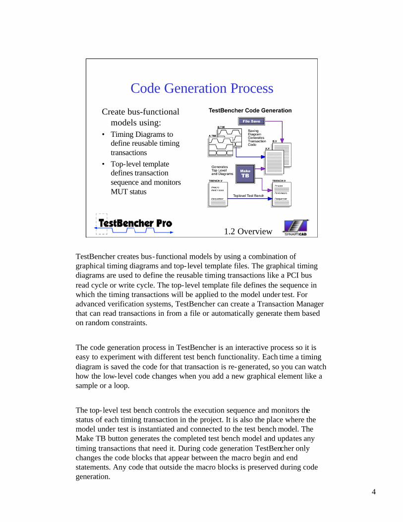
TestBencher creates bus-functional models by using a combination of graphical timing diagrams and top- level template files. The graphical timing diagrams are used to define the reusable timing transactions like a PCI bus read cycle or write cycle. The top- level template file defines the sequence in which the timing transactions will be applied to the model under test. For advanced verification systems, TestBencher can create a Transaction Manager that can read transactions in from a file or automatically generate them based on random constraints.
The code generation process in TestBencher is an interactive process so it is easy to experiment with different test bench functionality. Each time a timing diagram is saved the code for that transaction is re-generated, so you can watch how the low-level code changes when you add a new graphical element like a sample or a loop.
The top- level test bench controls the execution sequence and monitors the status of each timing transaction in the project. It is also the place where the model under test is instantiated and connected to the test bench model. The Make TB button generates the completed test bench model and updates any timing transactions that need it. During code generation TestBencher only changes the code blocks that appear between the macro begin and end statements. Any code that outside the macro blocks is preserved during code generation.
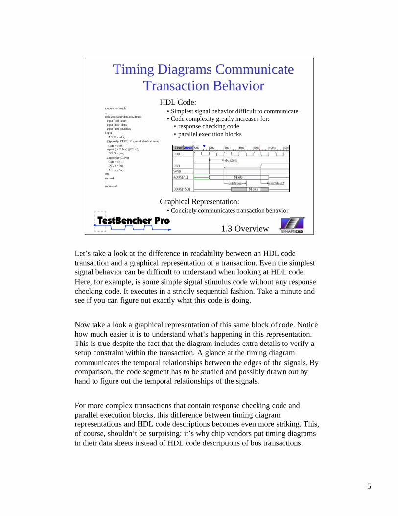
Let’s take a look at the difference in readability between an HDL code transaction and a graphical representation of a transaction. Even the simplest signal behavior can be difficult to understand when looking at HDL code. Here, for example, is some simple signal stimulus code without any response checking code. It executes in a strictly sequential fashion. Take a minute and see if you can figure out exactly what this code is doing.
Now take a look a graphical representation of this same block ofcode. Notice how much easier it is to understand what’s happening in this representation. This is true despite the fact that the diagram includes extra details to verify a setup constraint within the transaction. A glance at the timing diagram communicates the temporal relationships between the edges of the signals. By comparison, the code segment has to be studied and possibly drawn out by hand to figure out the temporal relationships of the signals.
For more complex transactions that contain response checking code and parallel execution blocks, this difference between timing diagram representations and HDL code descriptions becomes even more striking. This, of course, shouldn’t be surprising: it’s why chip vendors put timing diagrams in their data sheets instead of HDL code descriptions of bus transactions.
6
Sequencing Transactions• Sequencer Process controls order
in which transactions are applied to the MUT.
• Transactions can run sequentially in a blocking mode or concurrently.
• Transactions can be set to run once or run in a continuously looping mode
• Transaction calls are automatically generated using a dialog interface
1.4 Overview
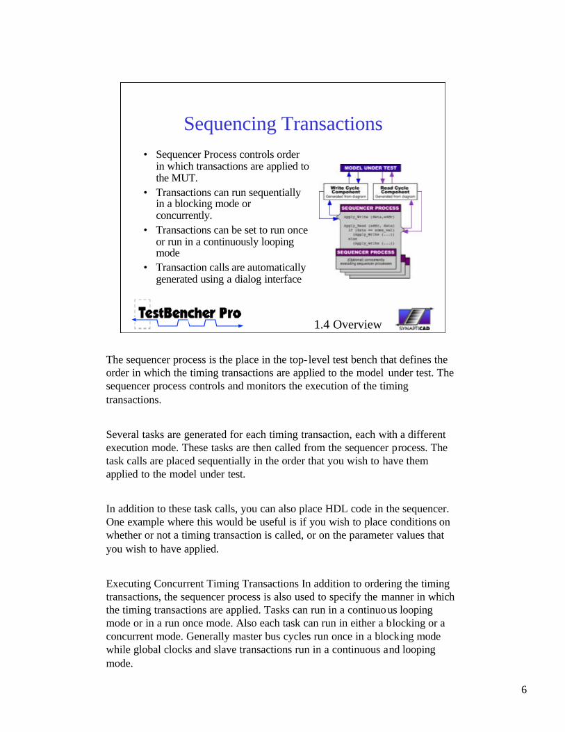
The sequencer process is the place in the top- level test bench that defines the order in which the timing transactions are applied to the model under test. The sequencer process controls and monitors the execution of the timing transactions.
Several tasks are generated for each timing transaction, each with a different execution mode. These tasks are then called from the sequencer process. The task calls are placed sequentially in the order that you wish to have them applied to the model under test.
In addition to these task calls, you can also place HDL code in the sequencer. One example where this would be useful is if you wish to place conditions on whether or not a timing transaction is called, or on the parameter values that you wish to have applied.
Executing Concurrent Timing Transactions In addition to ordering the timing transactions, the sequencer process is also used to specify the manner in which the timing transactions are applied. Tasks can run in a continuous looping mode or in a run once mode. Also each task can run in either a blocking or a concurrent mode. Generally master bus cycles run once in a blocking mode while global clocks and slave transactions run in a continuous and looping mode.
7
Transaction ManagerTransaction Manager maintains a queue of transactions to
be executed. Accepts transactions from many sources:
• Transactions read from a file• Other BFM models in the
verification hierarchy• Transaction Apply calls made
by the user in the template file• Transactions spawned by other
transactions• Randomly generated
transactions produced by the Transaction Generator (in DAC release)
1.5 Overview
In addition to sequentially executing transaction calls that are placed in the template file, TestBencher can generate a transaction manager module that maintains a queue of transactions to be executed. Transactions can be generated randomly, posted to the queue during simulation, or read in from a file using the Test Reader component.
TestBencher automatically generates Transaction Manager and Test Reader code from the transactions included in the project. Attempting to create and maintain this type of code manually is difficult because the code changes each time you add a new transaction type or change the number and types of parameters for a transaction.
During simulation, the Transaction Manager maintains a queue of transactions to be executed. The manager can randomly generate transactions to fill the queue based on a weighted function. Transaction Diagrams can dynamically post other transaction calls to the queue based on responses from the model under test. Each BFM has its own transaction manager, so a top- level BFM model can generate test sequences and post them to its child BFM transaction managers. All calls to transactions can be specified either as relative or fixed path, allowing any transaction to be initiated from anywhere in the test bench.
8
Transaction Monitor & GeneratorTransaction Monitor and Generator work together to
accumulate statistics on what transactions occur, and then dynamically adjust the randomization constraints to ensure important test cases are covered. (By DAC)
1.6 Overview
The Transaction Monitor and Generator work together to accumulate statistics on what transactions occur, and then dynamically adjust the randomization constraints to ensure important test cases are covered. Both the types of transactions and the input data for the transactions can be randomized. The user can specify coverage levels required before test will finish. The Transaction Monitor generates a coverage report for the completed test.
9
2.0 Graphical ConstructsSimple set of graphical constructs naturally express
timing and bus protocols:• Waveforms - stimulus and expected response • Variables - parameterize state and timing values
• Delays - parameterize time delays• Setups & Holds - monitor stability between transitions• Samples - verify and react to output from MUT
• Markers - model looping constructs, insert native HDL subroutine calls, or end transaction
We have given an overview of TestBencher and gone over the basic steps required create a test bench. Next we will talk about the graphical constructs used to create the bus transactions. TestBencher is easy to use because we have taken great care to keep the number of constructs down to a minimum. There are 5 basic constructs that are used to create a transaction.
Drawn waveforms provide quick way describe the basic functionality of a transaction. Usually the waveforms already exist in the design specifications or data sheets of the accompanying parts, so it is a simple exercise in importing a TDML file or redrawing a waveform specification.
State Variables allow flexible re-use of transactions by parameterizing the states so that new values can be passed in each time the transaction executes. For example, one use would be to provide data and address values for a write cycle transaction.
Delays provide a mechanism to parameterize time in the same way that state variable parameterize waveform values.
Samples provide a reactive, self-testing mechanism for checking the response of the model under test. Samples can monitor response at a particular point or over a time period.
Markers are used to create conditional loops for variable burst transactions, calling native HDL subroutine calls, or ending transactions.We will cover each of these constructs in detail in the next few slides.
10
Waveforms Provide Stimulus and Expected Response Information
Several methods available for waveform entry:• Graphically draw stimulus/response waveforms
• Generate waveforms using RTL-level equations• Import from simulators: VHDL, Verilog, SPICE• Import from logic analyzers: Agilent, Tektronix
• Import state information from spreadsheets
2.1 Graphical Constructs
State information is represented by waveforms. TestBencher Pro includes a professional timing diagram editor that allows you to quickly draw waveforms using the 7 graphical states or by describing the waveform using an RTL level equation or Time Based Waveform equation.
In addition to the drawing environment, TestBencher can import waveforms from other simulators, logic analyzers, and spreadsheets. TestBencher also supports the Timing Diagram Markup Language, TDML. This is the standard being adopted by semiconductor manufacturers and used in on- line data sheets.
The toolbar for the timing diagram editor is shown in this image. The first group of buttons are used to add signal objects to the diagram. The next group of buttons are used to add the model constructs discussed in the previous slide. Waveforms can be drawn using the state buttons in the middle of the toolbar, and the last set of buttons can be used to zoom the diagram view in or out.
11
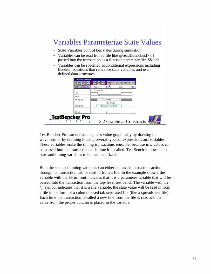
Variables Parameterize State Values • State Variables control bus states during simulation• Variables can be read from a file like @readData.dbus[7:0]
passed into the transaction as a function parameter like $$addr • Variables can be specified as conditional expressions including
Boolean equations that reference state variables and user-defined data structures.
2.2 Graphical Constructs
TestBencher Pro can define a signal's value graphically by drawing the waveform or by defining it using several types of expressions and variables. These variables make the timing transactions reusable, because new values can be passed into the transaction each time it is called. TestBencher allows both state and timing variables to be parameterized.
Both the state and timing variables can either be passed into a transaction through its transaction call or read in from a file. In the example shown, the variable with the $$ in front indicates that it is a parameter variable that will be passed into the transaction from the top- level test bench.The variable with the @ symbol indicates that it is a file variable; the state value will be read in from a file in the form of a column-based tab separated file (like a spreadsheet file). Each time the transaction is called a new line from the file is read and the value from the proper column is placed in the variable.
12
Delays Parameterize Time Values• Delays can conditionally control when edges occur• Delay values can be time or cycle-based• Delay values can be passed in from a function call or read
in from a file
2.3 Graphical Constructs
Delay variables, like state variables, can be either passed into the transaction or read from a file. Delays also can either be time based or cycle based. For example you can either pass in a value that means 5 ns or 5 clock cycles depending on how the delay is defined.
13
Samples Verify MUT Output• Sample constructs can monitor and perform actions based
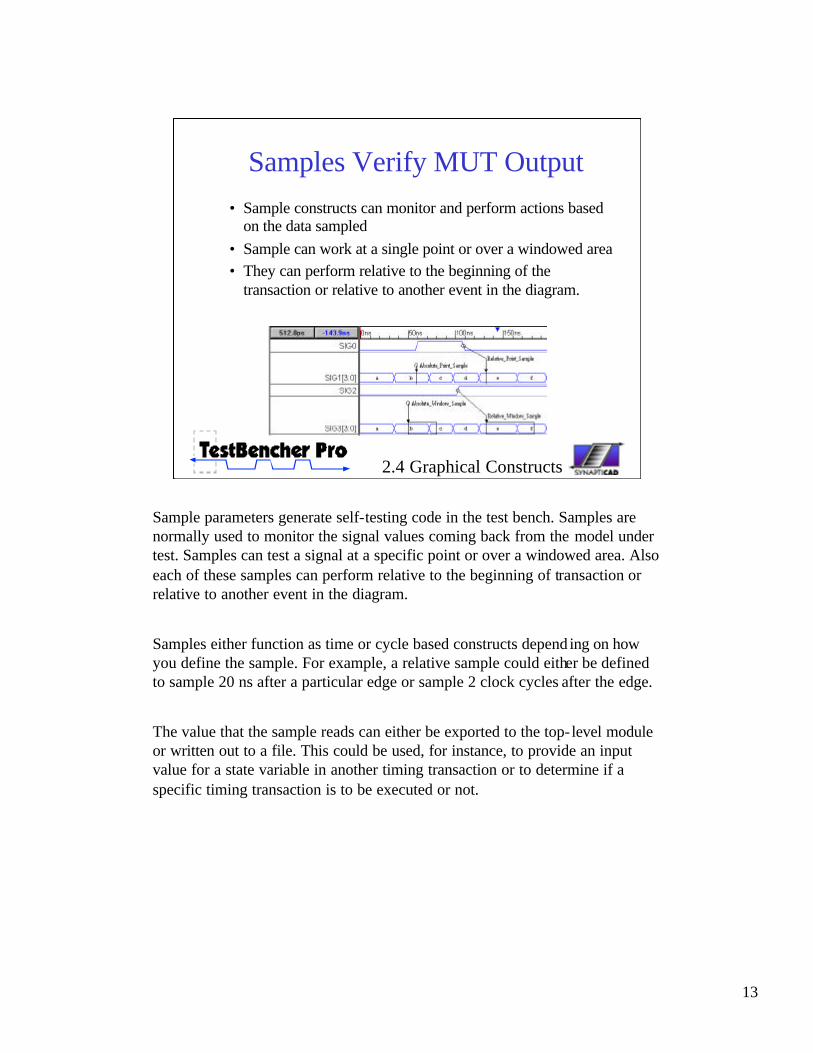
on the data sampled• Sample can work at a single point or over a windowed area • They can perform relative to the beginning of the
transaction or relative to another event in the diagram.
2.4 Graphical Constructs
Sample parameters generate self-testing code in the test bench. Samples are normally used to monitor the signal values coming back from the model under test. Samples can test a signal at a specific point or over a windowed area. Also each of these samples can perform relative to the beginning of transaction or relative to another event in the diagram.
Samples either function as time or cycle based constructs depend ing on how you define the sample. For example, a relative sample could either be defined to sample 20 ns after a particular edge or sample 2 clock cycles after the edge.
The value that the sample reads can either be exported to the top- level module or written out to a file. This could be used, for instance, to provide an input value for a state variable in another timing transaction or to determine if a specific timing transaction is to be executed or not.
14
Markers used for Control & Looping Sections of Transactions
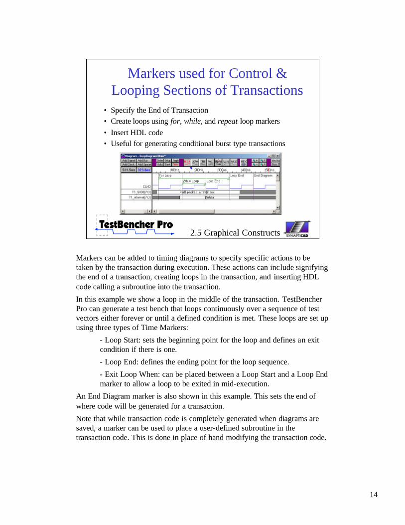
• Specify the End of Transaction• Create loops using for, while, and repeat loop markers• Insert HDL code• Useful for generating conditional burst type transactions
2.5 Graphical Constructs
Markers can be added to timing diagrams to specify specific actions to be taken by the transaction during execution. These actions can include signifying the end of a transaction, creating loops in the transaction, and inserting HDL code calling a subroutine into the transaction.
In this example we show a loop in the middle of the transaction. TestBencher Pro can generate a test bench that loops continuously over a sequence of test vectors either forever or until a defined condition is met. These loops are set up using three types of Time Markers:
- Loop Start: sets the beginning point for the loop and defines an exit condition if there is one.
- Loop End: defines the ending point for the loop sequence.
- Exit Loop When: can be placed between a Loop Start and a Loop End marker to allow a loop to be exited in mid-execution.
An End Diagram marker is also shown in this example. This sets the end of where code will be generated for a transaction.
Note that while transaction code is completely generated when diagrams are saved, a marker can be used to place a user-defined subroutine in the transaction code. This is done in place of hand modifying the transaction code.
• Fast conversion from time- to cycle-based test benches
• External Simulation and Compiler Control
So far we have covered the basic Use Model of TestBencher and introduced the major components that are generated for the verification system. Next, we will mention a few of the features that make TestBencher a powerful and easy to use environment for generating bus-functional models including: hierarchical BFM components, Golden reference model generation, file I/O code generation, the ability to switch between cycle and time base. And finally the ability to control external simulators.
16
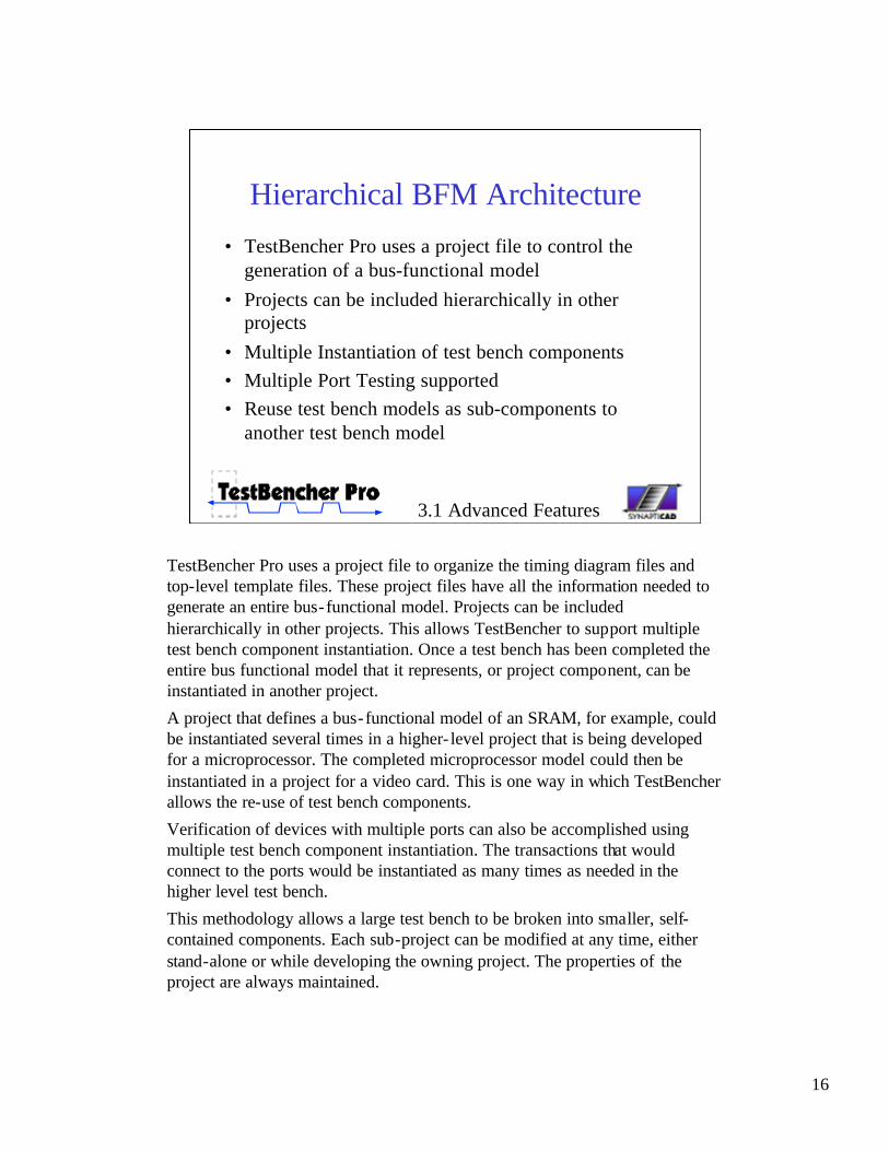
Hierarchical BFM Architecture• TestBencher Pro uses a project file to control the
generation of a bus-functional model• Projects can be included hierarchically in other
projects• Multiple Instantiation of test bench components• Multiple Port Testing supported• Reuse test bench models as sub-components to
another test bench model
3.1 Advanced Features
TestBencher Pro uses a project file to organize the timing diagram files and top-level template files. These project files have all the information needed to generate an entire bus-functional model. Projects can be included hierarchically in other projects. This allows TestBencher to support multiple test bench component instantiation. Once a test bench has been completed the entire bus functional model that it represents, or project component, can be instantiated in another project.
A project that defines a bus-functional model of an SRAM, for example, could be instantiated several times in a higher- level project that is being developed for a microprocessor. The completed microprocessor model could then be instantiated in a project for a video card. This is one way in which TestBencher allows the re-use of test bench components.
Verification of devices with multiple ports can also be accomplished using multiple test bench component instantiation. The transactions that would connect to the ports would be instantiated as many times as needed in the higher level test bench.
This methodology allows a large test bench to be broken into smaller, self-contained components. Each sub-project can be modified at any time, either stand-alone or while developing the owning project. The properties of the project are always maintained.
17
Golden Reference ModelGolden Reference Models are high-level descriptions of
a system that are used to automate the verification of system output
• Generates all of the stub functions for golden model• User writes behavioral code inside stub functions• Automatically compares MUT output against golden
reference model during simulation and reports errors
3.2 Advanced Features
TestBencher can generate C++ and Verilog golden reference models that run in parallel with a VHDL or Verilog RTL model. Golden reference models are high- level behavioral descriptions of a design and are used to compare against the results of an RTL-level model during simulation. Reference models usually model interaction between components at the transaction level (e.g. read transaction/write transaction) instead of at the signal level.
If reference model generation is enabled in TestBencher, the transactors will apply a time-based transaction to the MUT and an untimed function call transaction to the reference model. At the end of each transaction, the outputs for the MUT and the reference model are compared, and an error is logged whenever there is a mismatch in the output.
TestBencher generates all of the stub-functions for the golden reference model, keeping the transaction interface to the reference model the same as the HDL level model. TestBencher uses the TestBuilder library to generate the C++ models. The user writes the behavioral C++ or Verilog code inside the stub-functions that enables the golden reference model to emulate the RTL-level model.
18
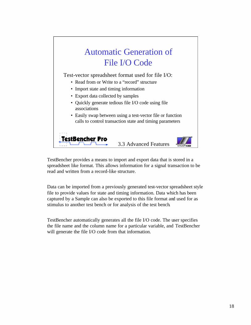
Automatic Generation of File I/O Code
Test-vector spreadsheet format used for file I/O:• Read from or Write to a “record” structure• Import state and timing information• Export data collected by samples• Quickly generate tedious file I/O code using file
associations • Easily swap between using a test-vector file or function
calls to control transaction state and timing parameters
3.3 Advanced Features
TestBencher provides a means to import and export data that is stored in a spreadsheet like format. This allows information for a signal transaction to be read and written from a record-like structure.
Data can be imported from a previously generated test-vector spreadsheet style file to provide values for state and timing information. Data which has been captured by a Sample can also be exported to this file format and used for as stimulus to another test bench or for analysis of the test bench.
TestBencher automatically generates all the file I/O code. The user specifies the file name and the column name for a particular variable, and TestBencher will generate the file I/O code from that information.
19
Switching between Time-based and Cycle-based test benches
Supports time and cycle-based test benches• Specify a clock signal to switch to cycle based• All signals, delays, samples, and markers have the
clocking feature• Supports sensitivity to multiple clock edges
• positive, negative, or both clock edges
• Supports multiple clocks
3.4 Advanced Features
Timing Diagrams can be used to either express cycle based or timing based transactions. By changing the clocking signal for the diagram components you can change the whether or not a cycle based transaction or a time based transaction will be generated. This makes it very quick to generate test benches for different applications: gate- level timing tests or for large cycle-based runs.
All of the graphical constructs in the timing diagram support both cycle and time based generation.
TestBencher Pro also supports multiple clocks and triggering on multiple clock edges.
20
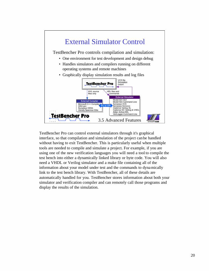
External Simulator ControlTestBencher Pro controls compilation and simulation:
• One environment for test development and design debug • Handles simulators and compilers running on different
operating systems and remote machines• Graphically display simulation results and log files
3.5 Advanced Features
TestBencher Pro can control external simulators through it's graphical interface, so that compilation and simulation of the project can be handled without having to exit TestBencher. This is particularly useful when multiple tools are needed to compile and simulate a project. For example, if you are using one of the new verification languages you will need a tool to compile the test bench into either a dynamically linked library or byte code. You will also need a VHDL or Verilog simulator and a make file containing all of the information about your model under test and the commands to dynamically link to the test bench library. With TestBencher, all of these details are automatically handled for you. TestBencher stores information about both your simulator and verification compiler and can remotely call those programs and display the results of the simulation.
21
VHDL, Verilog, & C++• C++ Library Support
using TestBuilder • Constrained Random
Data Structure Generation
• External control of simulator and compiler
3.6 Advanced Features
TestBencher can generate pure VHDL, Verilog, and C++ bus-functional models as well as mixed Verilog-C++ and VHDL C++ models. TestBencher generates all of the low-level transaction code, verification code, sequence detection, error reporting and file I/O code. Once the code gene ration is complete, TestBencher can launch external simulators and compilers necessary to build and simulate the design.
TestBencher uses the open source TestBuilder C++ library for all of the C++ generation. This library provides many useful test bench capabilities, including constrained random data generation and support for complex data structures. TestBuilder also provides an easier method for integrating C/C++ based models into a test bench than using a PLI-based approach (C-based models are often used as a golden reference to compare an RTL-level model against during simulation).
22
Test Bencher Summary• TestBencher Pro reduces the time required to create and
maintain test benches in VHDL, Verilog, and C++.• Features include external simulator control, sequence
recognition, conditional execution, hierarchical, and multiple instantiation of test bench projects
• TestBencher can model the most advanced verification problems: PCI, ARM, and ATM
• Easy four-step process to create a test bench
• Timing Diagrams are a natural way to express timing protocols.
In Summary, TestBencher Pro dramatically reduces the time required to create and maintain test benches. The user is free to concentrate on the more important aspects of test bench design since the most tedious aspects of code generation are abstracted away.
Features include external simulator control, sequence recognition, conditional execution, hierarchical, and multiple instantiation of test bench projects
TestBencher can model the most advanced verification problems: PCI, ARM, and ATM
Using this tool, Test Benches are constructed using a quick four-step process. The timing diagrams that are used to create the bus transactions are a natural way to express timing protocols and are usually included in the design specification or in data sheets of the parts surrounding the design.