VOLUME 15, NUMBER 2, 2005 LINCOLN LABORATORY JOURNAL 181 T he advanced land imager ( ali ) is an instru- ment that remotely senses multi-wavelength signals from its location on the Earth Observ- ing 1 (EO-1) satellite. The project’s primary goal was to validate the technologies utilized in the instrument as part of National Aeronautics and Space Administra- tion’s (NASA) New Millennium Program. The capa- bilities of current Landsat imagers served as a bench- mark to surpass, especially in the areas of payload size, mass, and power consumption. Organization All of Lincoln Laboratory’s mechanical engineering ef- forts for the ALI were grouped into the Payload Engi- neering Organization (PEO). As shown in Figure 1, the efforts were divided into five engineering sub-areas, namely, configuration, control electronics, thermal de- sign, structures and mechanisms, and fabrication. In addition to the Laboratory’s efforts, major hardware was provided by two subcontractors. The telescope was built by the Space Sensors Group (SSG) in Wilm- ington, Massachusetts, and the focal plane was built by Raytheon Santa Barbara Remote Sensing (SBRS). Lincoln Laboratory integrated these subsystems into an instrument infrastructure prior to testing, calibra- tion, and ultimately orbital launch and operation. The author was responsible for the overall manage- ment of the PEO. Each area was assigned one or more unit engineers over the course of the instrument’s de- velopment. Figure 1 lists the Lincoln Laboratory en- gineers for each area. SSG and SBRS also appointed unit engineers for the telescope and focal plane, and these people worked closely with their Lincoln Labo- ratory counterparts. System Configuration and Requirements Figure 2 illustrates all the exterior elements of the ALI instrument with the multilayer insulation removed for clarity. This exterior view shows the following ele- ments: mounting pallet; focal-plane electronics (FPE) box, radiator, and supports; ALI control electronics (ALICE) box; telescope housing; housing top plate with the aperture-cover assembly and its open-close mechanism and the aperture-selector mechanism; and the focal-plane array radiator, sun shield and conduc- tor bar. Figure 3 shows a cross-sectional view through the housing. Illustrated here are the telescope and optics, the calibration plate mechanism, and the fo- Advanced Land Imager: Mechanical Design, Integration, and Testing Steven E. Forman n The Advanced Land Imager (ALI), currently in operation on the Earth Observing 1 (EO-1) satellite, was developed at Lincoln Laboratory during the period from mid 1996 through early 1999. Within significant constraints of size, mass, power consumption, and cost, the ALI was designed to improve on the current Landsat land-sensing satellite technology, providing spectral and radiometric data with high resolution and stability. This article describes the mechanical design, integration, and testing of the ALI at Lincoln Laboratory prior to the launch of the EO-1 satellite in November 2000.
Transcript
• formanAdvanced Land Imager: Mechanical Design, Integration, and Testing
VOLUME 15, NUMBER 2, 2005 LINCOLN LABORATORY JOURNAL 181
The advanced land imager (ali) is an instru-ment that remotely senses multi-wavelength signals from its location on the Earth Observ-
ing 1 (EO-1) satellite. The project’s primary goal was to validate the technologies utilized in the instrument as part of National Aeronautics and Space Administra-tion’s (NASA) New Millennium Program. The capa-bilities of current Landsat imagers served as a bench-mark to surpass, especially in the areas of payload size, mass, and power consumption.
organization
All of Lincoln Laboratory’s mechanical engineering ef-forts for the ALI were grouped into the Payload Engi-neering Organization (PEO). As shown in Figure 1, the efforts were divided into five engineering sub-areas, namely, configuration, control electronics, thermal de-sign, structures and mechanisms, and fabrication. In addition to the Laboratory’s efforts, major hardware was provided by two subcontractors. The telescope was built by the Space Sensors Group (SSG) in Wilm-ington, Massachusetts, and the focal plane was built by Raytheon Santa Barbara Remote Sensing (SBRS). Lincoln Laboratory integrated these subsystems into
an instrument infrastructure prior to testing, calibra-tion, and ultimately orbital launch and operation.
The author was responsible for the overall manage-ment of the PEO. Each area was assigned one or more unit engineers over the course of the instrument’s de-velopment. Figure 1 lists the Lincoln Laboratory en-gineers for each area. SSG and SBRS also appointed unit engineers for the telescope and focal plane, and these people worked closely with their Lincoln Labo-ratory counterparts.
System Configuration and requirements
Figure 2 illustrates all the exterior elements of the ALI instrument with the multilayer insulation removed for clarity. This exterior view shows the following ele-ments: mounting pallet; focal-plane electronics (FPE) box, radiator, and supports; ALI control electronics (ALICE) box; telescope housing; housing top plate with the aperture-cover assembly and its open-close mechanism and the aperture-selector mechanism; and the focal-plane array radiator, sun shield and conduc-tor bar. Figure 3 shows a cross-sectional view through the housing. Illustrated here are the telescope and optics, the calibration plate mechanism, and the fo-
Advanced Land Imager: Mechanical Design, Integration, and TestingSteven E. Forman
n The Advanced Land Imager (ALI), currently in operation on the Earth Observing 1 (EO-1) satellite, was developed at Lincoln Laboratory during the period from mid 1996 through early 1999. Within significant constraints of size, mass, power consumption, and cost, the ALI was designed to improve on the current Landsat land-sensing satellite technology, providing spectral and radiometric data with high resolution and stability. This article describes the mechanical design, integration, and testing of the ALI at Lincoln Laboratory prior to the launch of the EO-1 satellite in November 2000.
• formanAdvanced Land Imager: Mechanical Design, Integration, and Testing
182 LINCOLN LABORATORY JOURNAL VOLUME 15, NUMBER 2, 2005
Telescope engineering
Space Sensors Group
Focal-plane engineering
Raytheon Santa BarbaraRemote Sensing
• Interface control documentation
• Interface control
• Mass and center of gravity tracking
• Environmental specifications and testing
• Mission assurance
• ALICE electrical requirements definition
• Mechanism- and thermal-control system design
• Mechanism-motor evaluation and procurement
• Cabling and connector design and selection
• System thermal requirements
• Thermal design, analysis, and testing
• Radiator design
• Evaluation of thermal aspects of subcontracts
• Thermal interface design
• System structural analysis
• Mechanism design, analysis, and testing
• Materials testing
• Evaluation of structural aspects of subcontracts
• Structural interface design
• MGSE
• ALICE chassis design
• Parts procurement
• Materials procurement
• Electrical and mechanical fabrication and assembly
• Fabrication programming
• J. Garcia• R. Nagle• E. Huang
System-levelconfigurationengineering
• J. Garcia• R. Nagle• E. Huang
Control-electronicsengineering• C. Much• L. Bernotas• D. Brosnan
Structure andmechanismengineering
• K. Doyle• V. Cerrati
Fabricationplanning andengineering
• D. Paquet• D. Mandeville
Thermal designand engineering
• D. Nathanson• R. Efromson• E.I. Lee
FIGURE 1. Payload Engineering Organization for mechanical engineering development of the Advanced Land Imager (ALI). The unit engineers listed above were responsible for their respective engineering groups. MGSE is the Mechanical Ground Support Equipment and ALICE denotes the Advanced Land Imager Control Electronics.
FIGURE 2. View of the ALI with the multilayer insulation removed. The positioning of the ancillary components complied with the goals of compactness and mass distribution.
Velocity vector +x
+z
+y
Telescopehousing
Housingtop plate
Pallet
Aperture-covermechanism
Focal-planeelectronics box
and radiator
ALI controlelectronics box
and radiator
Aperture cover
Aperture-selector
mechanism
Sun andearth shield
Focal-planearray radiator
Focal-plane arrayconductor bar
• formanAdvanced Land Imager: Mechanical Design, Integration, and Testing
VOLUME 15, NUMBER 2, 2005 LINCOLN LABORATORY JOURNAL 183
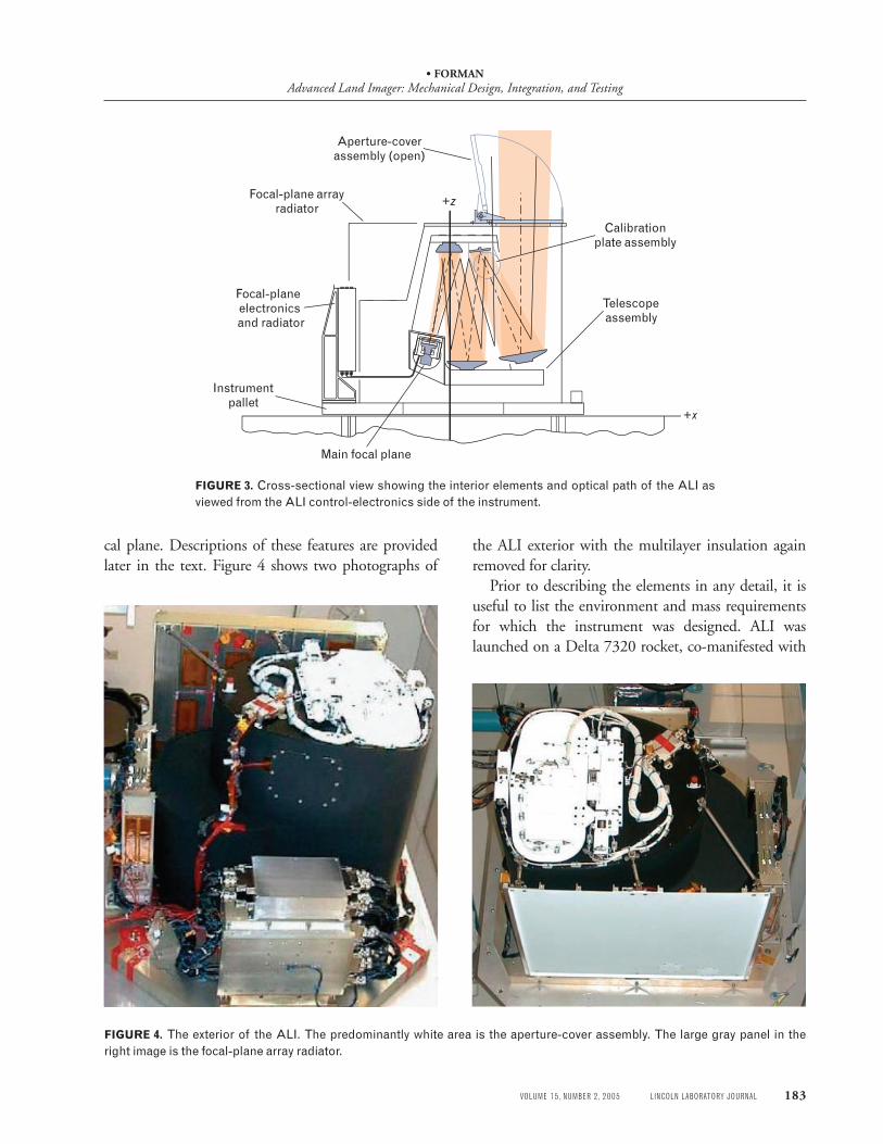
cal plane. Descriptions of these features are provided later in the text. Figure 4 shows two photographs of
the ALI exterior with the multilayer insulation again removed for clarity.
Prior to describing the elements in any detail, it is useful to list the environment and mass requirements for which the instrument was designed. ALI was launched on a Delta 7320 rocket, co-manifested with
+z
+x
Telescopeassembly
Calibrationplate assembly
Instrumentpallet
Aperture-coverassembly (open)
Focal-plane arrayradiator
Focal-plane electronics
and radiator
Main focal plane
FIGURE 3. Cross-sectional view showing the interior elements and optical path of the ALI as viewed from the ALI control-electronics side of the instrument.
FIGURE 4. The exterior of the ALI. The predominantly white area is the aperture-cover assembly. The large gray panel in the right image is the focal-plane array radiator.
• formanAdvanced Land Imager: Mechanical Design, Integration, and Testing
184 LINCOLN LABORATORY JOURNAL VOLUME 15, NUMBER 2, 2005
Table 1. Material Property Comparisons
CTE E r k (ppm/K) (gPa) (g/cm3) (W/mK)
Silicon carbide 2.2 427 3.2 165
Invar 36 1.6 141 8.1 10.5
Argentina’s SAC-C spacecraft. The quasi-static design limit loads for ALI were 12.2 g in the axial direction (z direction of Figure 2) and 9.6 g in each of the lateral directions (x and y). The minimum natural frequency was set at 65 Hz to avoid the 35 Hz axial mode of the launching rocket, and the allotted ALI mass was 90 kilograms. The expected operational temperature range for the telescope was –10° to +40°C, while the focal plane was nominally operated at 220 K. The de-sign lifetime minimum was set as one year.
Optomechanics and Structures
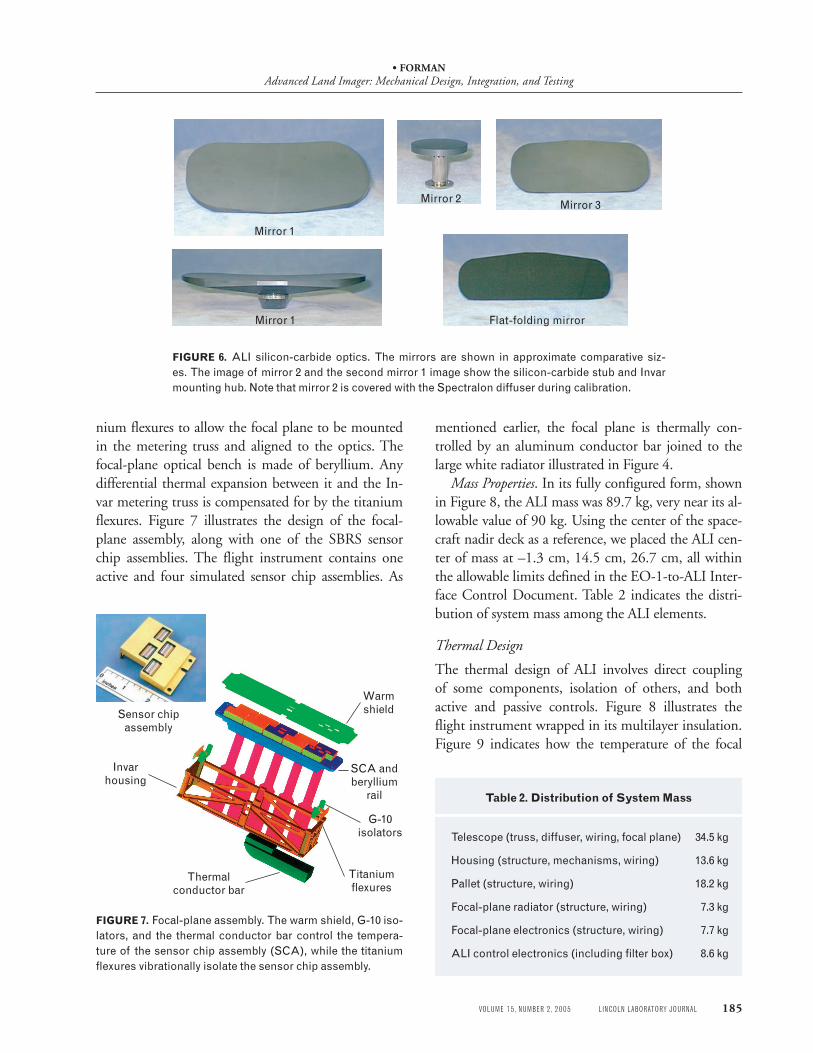
Initially, we planned to use four silicon-carbide mir-rors mounted in a silicon-carbide metering truss for the baseline design of the ALI telescope. The type of silicon carbide used was a version of hot pressed ma-terial known as Cercom Pad B. To accommodate the telescope’s wide field of view, we designed a single large plate to support the primary and tertiary mirrors and the focal plane. Manufacturing such a large plate (60 cm by 40 cm) with mounting holes proved dif-ficult because of the brittle nature of silicon carbide. To reduce telescope cost and for schedule reasons, we changed the truss material from silicon carbide to In-var 36 early in the program. Table 1 shows the coef-ficient of thermal expansion (CTE), Young’s Modulus (E ), mass density (r), and thermal conductivity (k) of the two materials. Clearly, Invar 36 is heavier and less stiff than silicon carbide, but it has a lower CTE and is considerably easier to machine. On the other hand, its thermal conductivity is quite low, which makes it susceptible to thermal gradients.
Figure 5 illustrates the progression from the com-puter-aided-design (CAD) model of the telescope to the machined and bolted Invar truss to the fully as-sembled telescope. We designed and fabricated the truss at Lincoln Laboratory. SSG provided the pol-ished mirrors and aligned them on the truss. The truss interior and exterior surfaces were painted with black Chemglaze Z-306.
Figure 6 shows the four silicon-carbide mirrors. Each mirror has an Invar mounting hub glued to a silicon-carbide stub, integrally machined on the back side of each mirror, for attachment and alignment in the metering truss. Once completed, the metering truss is attached to a lightweight aluminum pallet with three kinematic titanium supports. We chose titanium for its thermal-isolation characteristics, and the kine-matic aspect allowed for differential thermal expan-sion between the Invar truss and the aluminum pallet. The thermal conductivity of titanium is 7.5 W/m-K, compared to 167 W/m-K for aluminum.
SBRS provided Lincoln Laboratory with the focal plane and focal-plane electronics. We designed an In-var housing with fiberglass thermal isolators and tita-
FIGURE 5. The three stages of development of the ALI metering truss with silicon-carbide optics. The original computer-aided-design (CAD) model is on the left, the middle image is the completed Invar truss, and the right image shows the completed telescope with the silicon-carbide mirrors in place.
• formanAdvanced Land Imager: Mechanical Design, Integration, and Testing
VOLUME 15, NUMBER 2, 2005 LINCOLN LABORATORY JOURNAL 185
nium flexures to allow the focal plane to be mounted in the metering truss and aligned to the optics. The focal-plane optical bench is made of beryllium. Any differential thermal expansion between it and the In-var metering truss is compensated for by the titanium flexures. Figure 7 illustrates the design of the focal-plane assembly, along with one of the SBRS sensor chip assemblies. The flight instrument contains one active and four simulated sensor chip assemblies. As
mentioned earlier, the focal plane is thermally con-trolled by an aluminum conductor bar joined to the large white radiator illustrated in Figure 4.
Mass Properties. In its fully configured form, shown in Figure 8, the ALI mass was 89.7 kg, very near its al-lowable value of 90 kg. Using the center of the space-craft nadir deck as a reference, we placed the ALI cen-ter of mass at –1.3 cm, 14.5 cm, 26.7 cm, all within the allowable limits defined in the EO-1-to-ALI Inter-face Control Document. Table 2 indicates the distri-bution of system mass among the ALI elements.
Thermal Design
The thermal design of ALI involves direct coupling of some components, isolation of others, and both active and passive controls. Figure 8 illustrates the flight instrument wrapped in its multilayer insulation. Figure 9 indicates how the temperature of the focal
Mirror 1
Mirror 1
Mirror 3
Flat-folding mirror
Mirror 2
FIGURE 6. ALI silicon-carbide optics. The mirrors are shown in approximate comparative siz-es. The image of mirror 2 and the second mirror 1 image show the silicon-carbide stub and Invar mounting hub. Note that mirror 2 is covered with the Spectralon diffuser during calibration.
Sensor chipassembly
Invarhousing
Thermalconductor bar
SCA andberyllium
rail
Titaniumflexures
G-10isolators
Warmshield
FIGURE 7. Focal-plane assembly. The warm shield, G-10 iso-lators, and the thermal conductor bar control the tempera-ture of the sensor chip assembly (SCA), while the titanium flexures vibrationally isolate the sensor chip assembly.
Table 2. Distribution of System Mass
Telescope (truss, diffuser, wiring, focal plane) 34.5 kg
Housing (structure, mechanisms, wiring) 13.6 kg
Pallet (structure, wiring) 18.2 kg
Focal-plane radiator (structure, wiring) 7.3 kg
Focal-plane electronics (structure, wiring) 7.7 kg
ALI control electronics (including filter box) 8.6 kg
• formanAdvanced Land Imager: Mechanical Design, Integration, and Testing
186 LINCOLN LABORATORY JOURNAL VOLUME 15, NUMBER 2, 2005
plane is controlled. The aluminum conductor bar at the bottom of the array is linked to the large white ra-diator through a flexible coupling. If we look closely at the lower right-hand corner of the radiator in Fig-
ure 8, we can see the hexagonal bolt patterns of two cover plates, one of which covers the four attachment screws for the solid link of the coupling. The radiator is nominally held at 200 K on-orbit to control the fo-cal-plane temperature to 220 K. Strip heaters are lo-cated at selected sites on the radiator and conductor bar to control the focal-plane temperature; set points of 215, 220, 225, and 230 K can be selected through software commands to the ALICE. The radiator is painted with Illinois Institute of Technology Research Institute Z93P white paint.
The temperature of the ALI depends in part on the temperature of the nadir deck of the EO-1 space-craft. The ALI pallet is directly mounted to the deck with nineteen bolts, and the aluminum sheet-metal telescope housing is directly bolted to the pallet. The metering truss and the housing are painted black with Z-306. The metering truss is isolated from the pallet by its kinematic titanium feet. The optical performance of the metering truss requires that top-to-bottom thermal gradients be kept below 10 K to maintain focus. To limit these thermal gradients, strip heaters are located on the top and bottom truss plates, coupled to thermostats and activated by controls in the ALICE.
FIGURE 8. ALI with multilayer insulation. The regions with-out insulation are the aperture-cover assembly on top, the fo-cal-plane array radiator on the left, and the focal-plane elec-tronics box radiator on the lower right.
1.5 in × 1 in(3.8 cm × 2.5 cm)
cross section
Tapered radiator (white paint)27 in × 27 in (69 cm × 69 cm)
Main focal-plane array
220 K
Flexible link100 2 mil (0.05 mm) thick
aluminum foils1.5 in × 1 in (3.8 cm × 2.5 cm)
200 K Heater
Strip heaters
FIGURE 9. Attachment of focal plane to radiator. The focal-plane array is main-tained at 220 K by a localized heater and the thermal connection to the radiator.
• formanAdvanced Land Imager: Mechanical Design, Integration, and Testing
VOLUME 15, NUMBER 2, 2005 LINCOLN LABORATORY JOURNAL 187
The focal-plane electronics box, provided by SBRS, is thermally isolated from the pal-let, and a silver-Teflon-coated radiative sur-face 0.02 m2 in area is used to maintain its temperature near 300 K. The ALICE box is directly coupled to the pallet that is attached to the spacecraft nadir deck. The ALICE pro-vides thermal control of ALI, and the focal-plane electronics box provides fine thermal control of the focal plane.
Mechanisms
There are three primary mechanisms on the ALI: the aperture-cover door, the variable ap-erture-selector mechanism, and the second-ary-mirror diffuser. Each is described in fur-ther detail below.
The aperture-cover door can be opened or closed as needed during the mission. The door is machined from aluminum and paint-ed white with Z93P on the outside, and an-odized black on the inside. Figure 10 shows the aperture-cover assembly and the door. It is opened and closed by an Astro stepper motor CV4-A. The door is held closed during launch by the launch latch shown in Figure 11. The latch consists of two Starsys high-output paraffin actuators (HOPA) EP-5025, which engage a triangular clevis on a torsion spring-loaded shaft. On command, one actuator re-
leases, the clevis rotates, and the shaft springs out of the way, allowing the cover to open. Should the actua-tor fail to operate, a second actuator can be command-ed to operate, thus providing a redundant backup.
In the event the aperture-cover motor should fail at any time, there is a fail-safe mechanism controlled
Aperture-coverdoor
Launch hatch
Cover fail-safe
Aperture-selector
cover
FIGURE 10. Aperture-cover assembly mechanisms. The square open-ing of the aperture-selector cover opens to reveal a series of slits for solar calibration.
Paraffinactuator
Paraffinactuator
Clevis
Stowedposition
Trigger(torsion spring)
FIGURE 11. Launch latch mechanisms. An individual high-output paraffin actuator (HOPA) pin puller is shown in the right image to give an indication of its size.
• formanAdvanced Land Imager: Mechanical Design, Integration, and Testing
188 LINCOLN LABORATORY JOURNAL VOLUME 15, NUMBER 2, 2005
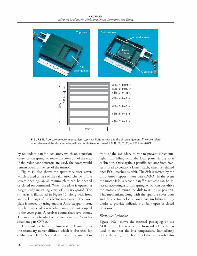
FIGURE 12. Aperture-selector mechanism; top view, bottom view, and the slit arrangement. The cover plate opens to reveal the slots in order, with a cumulative aperture of 1, 3, 10, 30, 50, 70, and 90 times 0.021 in.
Top view Bottom view
Lead screw
Coverplate
Guide rail
Slitarrangement
(Slot 1) 0.021 in(Slot 2) 0.042 in(Slot 3) 0.148 in
(Slot 4) 0.42 in
(Slot 5) 0.42 in
(Slot 6) 0.42 in
(Slot 7) 0.42 in
0.10
in
2.50
in
2.50 in
by redundant paraffin actuators, which on actuation cause torsion springs to rotate the cover out of the way. If the redundant actuators are used, the cover would remain open for the rest of the mission.
Figure 10 also shows the aperture-selector cover, which is used as part of the calibration scheme. In the square opening, an aluminum plate can be opened or closed on command. When the plate is opened, a progressively increasing array of slits is exposed. The slit array is illustrated in Figure 12, along with front and back images of the selector mechanism. The cover plate is moved by using another Astro stepper motor, which drives a ball screw, advancing a ball nut coupled to the cover plate. A resolver counts shaft revolutions. The motor-resolver-ball screw component is Astro In-strument part CV5-A.
The third mechanism, illustrated in Figure 13, is the secondary-mirror diffuser, which is also used for calibration. Here a Spectralon disk can be rotated in
front of the secondary mirror to prevent direct sun-light from falling onto the focal plane during solar calibration. Once again, a paraffin actuator from Star-sys is used to control a launch latch, which is released once EO-1 reaches its orbit. The disk is rotated by the third Astro stepper motor part CV3-A. In the event the motor fails, a second paraffin actuator can be re-leased, activating a torsion spring, which can backdrive the motor and return the disk to its initial position. This mechanism, along with the aperture-cover door and the aperture-selector cover, contain light-emitting diodes to provide indications of fully open or closed positions.
Electronics Packaging
Figure 14(a) shows the external packaging of the ALICE unit. The wire on the front side of the box is used to monitor the box temperature. Immediately below the wire, at the bottom of the box, a solid alu-
• formanAdvanced Land Imager: Mechanical Design, Integration, and Testing
VOLUME 15, NUMBER 2, 2005 LINCOLN LABORATORY JOURNAL 189
Launchlatch
Fail-safeHOPA
Spectralondiffuser
Secondarymirror
FIGURE 13. Secondary-mirror-calibration diffuser mechanism. The left image shows the diffuser in closed position, while the right image shows the diffuser in open position.
Integration and Testing
Since its launch on 21 November 2000, the ALI has proved to be a highly successful instrument. In dis-cussing the ground testing of ALI in this article, we particularly focus on test anomalies and their resolu-tion. These test anomalies should be considered in the context of ALI’s orbital success and for the way they were expeditiously handled during ALI’s development schedule. We conducted a thorough test campaign,
FIGURE 14. ALI Control Electronics (ALICE) packaging. (a) Three printed circuit boards are bonded to metal cores and thermally bonded to the pallet. (b) The panel containing the power converters, which generates the majority of the heat, is in front of the unit.
(a) (b)
minum bar is used to thermally connect the box to the pallet. Heat is generated by the power converters con-tained in the package shown lying on its side in Figure 14(b). Both chassis are machined aluminum. The AL-ICE contains three printed circuit boards that connect to a back plane and are secured in place by thermally conductive wedge clamps. Each board assembly con-sists of an aluminum heat sink with an active board on one side and a compensating board on the other for thermostructural symmetry.
• formanAdvanced Land Imager: Mechanical Design, Integration, and Testing
190 LINCOLN LABORATORY JOURNAL VOLUME 15, NUMBER 2, 2005
leaving sufficient time to find and resolve anomalies without compromising the delivery schedule.
Figure 15 shows the actual development schedule. The time from program start to spacecraft integration was slightly under three years. Because of this limited time period, we decided to minimize risk by building a structural thermal model (STM) in series with the de-velopment of the flight instrument. In this way, most integration, handling, and testing issues could be ad-dressed early, and any design deficiencies could be un-covered before being built into the flight instrument. The ensuing text provides discussion of the testing and the performance of both the STM and the flight unit. As is often the case in abbreviated programs, testing of the two models overlapped. While many correctable problems were found with the STM, the flight unit presented additional issues. We discuss the most sig-nificant of these issues below.
Structural Thermal model
Figure 2 shows a drawing of the ALI exterior without its multilayer insulation. Outwardly the STM and the flight unit appear the same. The primary differences are the lack of polished optics and a photon-sensi-tive focal plane in the STM, considerably reduced cleanliness, and simplified versions of ALICE and the focal-plane electronics.
The assembly phase of the STM allowed us to veri-fy all instrument interfaces and to develop an efficient assembly process. The first environmental exposure was vibration testing. NASA established the following quasi-static loads for ALI, on the basis of its position on the spacecraft: 12.2 g axial and 9.6 g lateral. The instrument was designed to withstand these loads by
using the following factors of safety: (1) 1.25 on mi-cro-yield stress (the stress at 10–6 strain) for optics or optical bearing elements; (2) 1.60 on yield stress (the stress at 0.002 strain); and (3) 2.0 on ultimate stress (the stress at which failure occurs). The minimum natural frequency imposed by Swales Aerospace, the spacecraft contractor, was 65 Hz (well above the 35 Hz axial mode of the Delta launch vehicle).
Vibration Testing
Vibration testing consisted of three types: sine burst testing to verify the static load design, and sine and random testing to verify the natural frequencies and workmanship. The use of sine burst testing to verify response to quasi-static loads was new to Lincoln Laboratory, since sine testing had not been previously used for that purpose. In fact, the sine test loads were notched by NASA during the program to prevent overtesting.
The sine burst loads were 12.2 g in the axial direc-tion and 9.6 g in each of the lateral directions. The
Table 3. Random Vibration Loads
Frequency Magnitude
20 Hz 0.01 g2/Hz
20–40 Hz +3 dB/octave
40–1000 Hz 0.02 g2/Hz
1000–2000 Hz –3 dB/octave
2000 Hz 0.01 g2/Hz
Calendar year 1996 1997 1998 1999 2000
Program start
Telescopedelivery
Focal-planedelivery
Launch
Spacecraftintegration
Design convergence review Pre-ship review
Critical design review Pre-environment review
FIGURE 15. Schedule for ALI during development of Earth Observing 1 (EO-1) satellite for calendar years 1996 to 2000.
• formanAdvanced Land Imager: Mechanical Design, Integration, and Testing
VOLUME 15, NUMBER 2, 2005 LINCOLN LABORATORY JOURNAL 191
vibration table was controlled to deliver the sine burst at a frequency of 20 Hz, well below the lowest natu-ral frequency of the STM. The sinusoidal sweep loads applied were 5.9 g from 20 to 35 Hz and 3.0 g from 35 to 50 Hz in the lateral direction; and 3.5 g from 12 to 50 Hz in the axial direction. Table 3 lists the random vibration loads applied to the STM. The inte-grated power spectral density of the random vibration amounts to 5.8 g root mean squared.
Two problems occurred during the STM vibration test; the fail-safe torsion spring in the calibration dif-fuser disengaged, and the flat folding mirror appeared to rotate by about 1.5°. (Note that small, flat mirrors were glued onto each of the four unpolished mirror blanks and the metering-truss top and bottom plates so that we could make angular position measurements before and after vibration testing.) Investigation of the calibration diffuser problem indicated that the engage-ment tangs on the torsion spring needed to be elon-gated to eliminate the problem. Analysis of the torque levels, necessary to cage the spring, led to the discovery of a more serious issue, namely, that deployment of the diffuser fail-safe damaged the diffuser motor. Since the fail-safe will be activated only if and when the dif-fuser motor fails, this damage is acceptable. However, one valuable lesson from the STM testing was that the flight-unit fail-safe should not be activated during
ground testing to avoid damaging the motor. SSG ul-timately traced the movement of the flat folding mir-ror to a workmanship problem during the application of adhesive to the mirror. Reapplying the adhesive solved the problem.
Thermal and Electromagnetic Testing
After vibration testing, we used the STM for elec-tromagnetic interference and compatibility tests and thermal-balance testing in vacuum. The thermal-bal-ance test demonstrated that the thermal design was robust and verified the thermal model. The test vali-dated the capability of the 200 K radiator to control the focal plane to 220 K as the temperature of the spacecraft nadir deck was varied between its limits of –10 to +50°C.
After thermal-balance testing, we removed the three mechanisms for life testing in a smaller vacuum cham-ber. Each mechanism was tested for one-and-a-half times its expected number of usage cycles. Half the cy-cles were performed at 0°C and the other half at 40°C. Prior to and after life-test completion, each mecha-nism was soaked at –10°C and 50°C, respectively. The aperture cover was cycled 3900 times, the aperture-se-lector mechanism for 240 cycles, and the calibration diffuser for 240 cycles. We encountered no problems during these tests.
28 April 98 3 Aug–2 Sept
25 Oct–22 Jan 99
3 Sept–24 Oct
3 March–16 March 16 March 16 March –22 March25 January–2 March
Telescope vibration, disassembly cleaning,
reassembly andrealignment
Focal-plane delivery,warm testing,
integration, alignment, and telescope
integration
Instrumentintegration
Calibration
Vibrationand thermal
cycling invacuum
1773 transceiverreplacement,
bake-out heaterinstallation
Pre-ship activities; resetting mechanisms,cleaning, packing, and
shipping
Deliveryto
Swales
Integrationwith
spacecraft
Flighttelescopedelivery
from SSG
28 April–7 July 19 June–3 Aug
FIGURE 16. Flight-unit development schedule. Testing of the Structural Thermal Model (STM) was performed concurrently with the pre-calibration stages of the flight unit.
• formanAdvanced Land Imager: Mechanical Design, Integration, and Testing
192 LINCOLN LABORATORY JOURNAL VOLUME 15, NUMBER 2, 2005
flight Unit
The ALI flight unit was integrated in a Class 10,000 clean room with a Class 100 optical bench and tested according to the sequence shown in Figure 16. The flight telescope arrived at Lincoln Laboratory from SSG at the end of April 1998.
Vibration Testing
Because of the problem with the flat folding mirror on the STM, we decided to do a series of vibration tests with the metering truss mounted to the pallet prior to the arrival of the focal plane. Accelerometers were placed on the back surfaces of each mirror by bonding them to Kapton tape placed on the mirror rear sur-faces. (Note that the adhesive on the Kapton tape had low outgassing in vacuum so as not to leave any con-taminating residue.)
We subjected the metering truss to sine burst, sine vibration, and random vibration tests. The mirror frequencies were carefully observed for significant fre-quency changes. Within the resolution of the data, no frequencies changed throughout the testing. We no-ticed two anomalies, however. First, there were large numbers of particles on the surface of the primary and tertiary mirrors and the metering-truss bottom plate. The particles consisted mostly of pieces of paint, and some metallic and plastic chips. Secondly, we found significant changes in the power spectral density (up to an order of magnitude) between the pre- and post-random white-noise signature tests for all four mirrors. The changes were most noticeable near each mirror’s lowest natural frequency. After considerable evalua-tion, we found the following causes.
Particulates. Most of the paint particles were gener-ated by the crumbling of masked paint edges during vibration. The metal and plastic particles came from fasteners with locking strips rubbing against threads inside their Helicoil inserts and threaded holes. Dur-ing the investigation, it was apparent that there was not universal agreement between NASA, SSG, and people in the paint industry over the best way to ap-ply Z-306 black paint. Most felt paint adhesion on a nickel-plated Invar surface would be enhanced by pre-application abrasion, which was not used by SSG’s painter. All agreed that scrubbing off loose paint at the
edges of mask lines would help minimize particulate generation.
Power Spectral Density Change. The mirror power spectral density changes were traced to overtightened bolts used to fasten the mirrors to their mounting surfaces during alignment in the metering truss. The bolts apparently had been torqued close to or above the yield strength of their material (A286 stainless steel), and the torques simply relaxed during the vibra-tion tests. In fact, during disassembly, the technician noticed that the bolts were easily removed with mini-mal removal torque application.
Results. We resolved both these problems by com-pletely disassembling the metering truss, scrubbing every masked edge, and thoroughly cleaning all of the parts. During reassembly and realignment, all bolts were tightened to the proper torque value. To pre-vent contamination by particles of metal and plastic, we covered all exposed bolt holes with bonded metal. During subsequent vibration testing, we minimized particle generation, and we observed no shifts in pow-er spectral density.
Integrated Vibration Testing
We realigned and retested the telescope prior to ar-rival of the flight focal plane. The flight focal plane was then aligned in the telescope metering truss, and all the components of the infrastructure were added to fully integrate the instrument. The elapsed time from the metering-truss delivery to the completion of in-strument integration was four months.
The fully integrated telescope underwent vibra-tion testing, as shown in Figure 17. We performed sine sweeps and random vibration tests along all three axes. The instrument was double bagged to prevent particulate contamination, because the vibration test equipment was not in a clean area. Notching random inputs ensured that no loads exceeded the quasi-static allowables. There were two exceptions to the test; we did not install multilayer insulation, and we used a mass mock-up for the ALICE, because it had not been fully completed at the time of the test.
After the test, the optics remained in focus, and we verified all electrical and mechanical functions. There were some paint particles on the primary and tertiary mirrors, but considerably fewer than when the
• formanAdvanced Land Imager: Mechanical Design, Integration, and Testing
VOLUME 15, NUMBER 2, 2005 LINCOLN LABORATORY JOURNAL 193
FIGURE 17. Flight instrument mounted on vibration table. A suite of triple-axis protoflight tests, including sine sweeps and random-level tests, were applied to the ALI.
metering-truss tests were conducted earlier. The most significant anomaly was that the aperture-selector mechanism was ajar by about 3 mm. We removed the particles by using a clean-room vacuum. The aperture-selector mechanism problem was traced to a loose jam nut, which we re-torqued and staked with epoxy. We performed additional vibration testing on the STM selector to verify that the modifications were effective in eliminating the problems.
Tables 4, 5, and 6 list the measured vibration test data showing frequencies and amplifications. The lowest natural frequency was 68 Hz, which was measured for the metering truss, the housing, and the focal-plane radiator. The maximum allowable quasi-static loads were not exceeded during the tests by either the sinusoidal responses or the 3σ random responses.
Thermal Testing
Once vibration testing was completed, we applied multilayer insulation, and we installed the ALI in a
Table 4. Resonant Frequencies
Component Frequency(Hz)
Telescope 68, 78, 170
Housing 68, 110
Focal-plane electronics 110, 180
ALICE 105, 180
Focal-plane radiator 68, 100, 190
Table 5. 3σ Random Peak Responses at fn < 200 Hz
Component X(g) Y(g) Z(g)
Maximum allowable values 9.6 9.6 12.2
Mirror 1 9.5 9.5 11.0
Housing 2.7 6.6 9.8
Focal-plane 3.7 2.8 4.2 electronics
ALICE 6.7 5.7 2.0
Focal-plane 4.6 6.8 6.4 radiator
clean-room vacuum tank for thermal-vacuum cycling and testing. Figure 18 shows a photograph of the vac-uum tank installation. We controlled the temperature of the ALI through a spacecraft simulator, which pro-vided an EO-1 nadir deck-temperature control and other heater plates facing radiating surfaces. Two of those heater plates are illustrated in Figure 18—one is facing the focal-plane radiator on the right side and the other is above the focal-plane electronics radiator at the top in the center of the tank.
For thermal survival tests, we conducted a cold soak at –30°C and a hot soak at +50°C. Four cycles were conducted between –10° and 40°C. During each cycle, we obtained ALI optical performance data at temperature plateaus. The only anomaly observed was in the control of the focal-plane temperature by the
• formanAdvanced Land Imager: Mechanical Design, Integration, and Testing
194 LINCOLN LABORATORY JOURNAL VOLUME 15, NUMBER 2, 2005
focal-plane electronics. To fix the problem, we imple-mented a new control system in the ALICE software, which subsequently moved thermal control from the focal-plane electronics to the ALICE. Most impor-tantly, we verified the ALI thermal computer model with good agreement between measured and predicted temperatures.
FIGURE 18. ALI in vacuum tank. Two heater plates are in po-sition for the thermal testing.
Table 6. Sine Sweep Component Responses
Component Xpeak(g) Ypeak(g) Zpeak(g)
5–35Hz 35–50Hz 5–35Hz 35–50Hz 5–35Hz 35–50Hz
Input 5.9 3.0 5.9 3.0 3.5 3.5
Telescope 8.2 7.0 7.0 7.0 3.8 4.4
Housing 7.0 4.6 9.2 9.8 4. 6.0
Focal-plane electronics 7.0 4.6 7.2 4.8 3.6 3.6
ALICE 5.8 3.3 6.0 3.2 3.9 4.1
Focal-plane radiator 8.1 6.2 9.4 20.0 4.0 3.6
Calibration and Integration
After completion of the environmental testing, ALI went through a three-month calibration period (see the article entitled “Spectral and Radiometric Cali-bration of the Advanced Land Imager” by Jeffrey A. Mendenhall et al., in this issue). During calibration, we noticed that a contaminant appeared to deposit on the focal plane and continued to build up as long as the focal plane was kept at 220 K. Raising the focal-plane temperature to 273 K caused the contaminant to evaporate. We suspected, but never proved, that the contaminant was an organic material that out-gassed from the interior black painted surfaces of the telescope or housing. We added a warm-up heater to the focal-plane radiator to evaporate the organic con-taminant on-orbit. Since the orbital mission operation started, we have used the heater quite effectively. Use of the warm-up heater is controlled by the spacecraft and not by the ALICE.
After calibration, we cleaned the instrument, reset the mechanisms, and readied the ALI for shipment to Swales Aerospace for integration with the spacecraft. The instrument was integrated mechanically to the spacecraft on 22 March 1999, as shown in Figure 19. It was the first of the EO-1 instruments to be integrat-ed. After integration, the instrument successfully com-pleted vibration testing, acoustic testing, and thermal-vacuum testing as part of EO-1, with no problems.
• formanAdvanced Land Imager: Mechanical Design, Integration, and Testing
VOLUME 15, NUMBER 2, 2005 LINCOLN LABORATORY JOURNAL 195
FIGURE 19. Installation of ALI on the EO-1 spacecraft at Swales Aerospace.
on-orbit Performance
The true measure of the adequacy of a space-instru-ment ground testing program is how well the instru-ment performs on-orbit. Until 5 July 2002, well be-yond the design lifetime minimum of one year, ALI performed flawlessly. The launch latch operated on command, the three mechanisms operated as com-manded, and the temperature distribution followed predictions. On 5 July, the aperture-selector mecha-nism ceased to operate in a controllable manner, which in no way stopped the ALI from operating effectively; it only curtailed the solar portion of the on-orbit cali-bration. We believe that a particle of some sort became jammed between the ball nut and ball screw, and the jam nut unscrewed itself from the ball nut. It is likely that the staking epoxy failed either during thermal soak, thermal cycling, vibration before launch, dur-ing launch, or on-orbit. In hindsight, a better design would have mechanically locked the jam nut to the ball nut instead of relying on staking epoxy.
Summary
Given the short time to develop the ALI, the ground integration and test period was effective in producing
a robust instrument for space. The ALI has performed well on-orbit. We learned many lessons during its in-tegration and testing period, especially in the areas of paint application, bolt torque, use of a ceramic mate-rial like silicon carbide, thermal control, and contami-nation control. The use of a structural thermal model of the flight instrument proved to be an invaluable tool in the final development of ALI. We continue to use it to illustrate the ALI design and to help under-stand instrument performance.
acknowledgments
The author gratefully acknowledges the contributions of the unit engineers overseeing the various areas of development of the project as well as to this article. The engineers appointed by SSG and SBRS and their close association with their Lincoln Laboratory coun-terparts are also gratefully acknowledged. The author also wishes to gratefully thank the many technicians, designers, assemblers, inspectors, and test engineers who aided in the integration and testing of ALI.
• formanAdvanced Land Imager: Mechanical Design, Integration, and Testing
196 LINCOLN LABORATORY JOURNAL VOLUME 15, NUMBER 2, 2005
steven e. formanis the leader of the Optical Sys-tems Engineering group. He joined the Laboratory in 1973 after spending four years at Bell Laboratories working on com-puter modeling of silicon ingot sawing and using high-pressure water jets as excavation tools. He received a B.S. degree in mechanical engineering from Northeastern University, and M.S. and Ph.D. degrees in engineering from Harvard University. His primary areas of technical expertise are the structural mechanics of elec-tronic and optical systems, space materials, and adhesives engineering. He has applied these skills on many projects at the Laboratory, including extremely low frequency and ultrahigh frequency subma-rine antennas, terrestrial and space solar photovoltaic device reliability, Space-Based Vis-ible (SBV) sensor, Airborne Infrared Imager (AIRI) pod systems, the Advanced Land Imager (ALI) for EO-1, digital radar receiver electronic pack-aging, the ALIRT and ALVIN airborne laser radars, and the Space-based Space-surveillance Next Generation (SSTING) space surveillance sensor. He is married to Barbara For-man, formerly of the Weather Sensing group, and they have three children and five grand-children. He enjoys mystery novels, crossword and Soduku puzzles, and tennis.