3 May 2013 VTU Belgaum 1 Criterion Attribute of testing method TerminologyWhen testing is performed?*concurrently with normal system operation*As a separate activity*Online/Concurrent Testing*Off line TestingWhere is the source ofstimuli?*within the system*By external device*Self Testing*External TestingWhat do we test for?*Design Errors*Fabrication errors *Fabrication Defects*Infancy physical failures*physical failures*Design Verification Testing*Acceptance Testing *Burn In testing*Quality Assurance Testing*Field/Maintenance TestingWhat is the Physical object being tested?*IC *Board*System *Component level Testing *Board level Testing*System level TestingHow are the stimuli applied?*In a fixed order*Depending upon results obtained so far *Ordered Testing*Adaptive TestingHow fast the stimuli applied?*Slower than normal operation speed*At the normal operation speed*DC(static) Testing*AC testingWhat are the Observed results?*The entire output patterns*some function of output patterns*Exhaustive testing*Compact TestingWhat lines are accessible for testing•Only the I/O lines •I/O and internal lines •Edge Pin Testing •Guided probe / Electron beam / In circuit Testing Who checks the results*The system itself*An external device(Tester)*Self checking/ Self Testing*External TestingTypes of Testing
Transcript
7/30/2019 Testing L3
http://slidepdf.com/reader/full/testing-l3 1/21
3 May 2013 VTU Belgaum 1
Criterion Attribute of testing method Terminology When testing is
Packaging failures Contact degradation Seal leaks . . .
3 May 2013 3VTU Belgaum
7/30/2019 Testing L3
http://slidepdf.com/reader/full/testing-l3 4/21
Errors and Faults
3 May 2013 4VTU Belgaum
7/30/2019 Testing L3
http://slidepdf.com/reader/full/testing-l3 5/21
• An instance of an incorrect operation of the systembeing tested is referred to as an error.
• The causes of the errors may be:
## Design errors
examples of design errors are:
– Incomplete or inconsistent specifications. – Incomplete mapping between different levels of design.
– Violations of design rules.
## Physical faults
Physical faults can be fabrication errors, fabricationdefects or physical failures.
3 May 2013 5VTU Belgaum
7/30/2019 Testing L3
http://slidepdf.com/reader/full/testing-l3 6/21
• Fabrication errors occur due to:
– Wrong components
– Incorrect wiring
– Shorts caused by improper soldering
• Fabrication defects result from an imperfect manufacturingprocess.
– Eg: shorts and opens are common defects.
• Other fabrication defects are due to:
– Improper doping profiles
– Mask alignment errors
– Poor encapsulation
• Accurate location of fabrication defects is important inimproving the manufacturing yield.
3 May 2013 6VTU Belgaum
7/30/2019 Testing L3
http://slidepdf.com/reader/full/testing-l3 7/21
• Physical failures occur during the lifetime of a system due
to component wear-out and/or environmental factors.
eg: aluminum connectors inside an IC package thin out withtime and may break because of electron migration or
corrosion.
• Environmental factors such as temperature, humidity,
vibrations and aging of components.#Fabrication errors, fabrication defects and physical failures
are collectively called Physical faults.
• Physical faults can be classified as:
– Permanent: always being present after their occurrence
– Intermittent: existing only during some intervals
– Transient: a one-time occurrence caused by a temporary
change in some environmental factor.3 May 2013 7VTU Belgaum
7/30/2019 Testing L3
http://slidepdf.com/reader/full/testing-l3 8/21
• Physical failures appear early after fabrication isreferred to as “infancy failures”.
• Physical faults do not allow a direct mathematicaltreatment of testing and diagnosis.
• The solution is to deal with logical faults (or fault
models), which are a convenient representation of the effect of the physical faults on the operation of the system.
• Since a fault is detected by observing an error
caused by it.• The basic assumption regarding the nature of logical
faults are referred to as fault model.
3 May 2013 8VTU Belgaum
7/30/2019 Testing L3
http://slidepdf.com/reader/full/testing-l3 9/21
3 May 2013 9VTU Belgaum
7/30/2019 Testing L3
http://slidepdf.com/reader/full/testing-l3 10/21
3 May 2013 VTU Belgaum 10
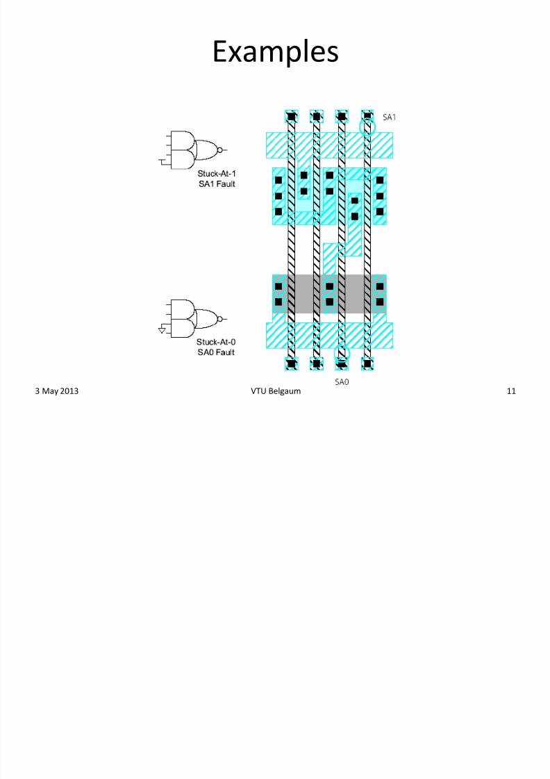
• How does a chip fail? – Usually failures are shorts between two conductors or
opens in a conductor
– This can cause very complicated behavior
• A simpler model: Stuck-At
– Assume all failures cause nodes to be “stuck-at” 0 or 1,
i.e. shorted to GND or VDD
– Not quite true, but works well in practice
7/30/2019 Testing L3
http://slidepdf.com/reader/full/testing-l3 11/21
3 May 2013 VTU Belgaum 11
Examples
7/30/2019 Testing L3
http://slidepdf.com/reader/full/testing-l3 12/21
3 May 2013 VTU Belgaum 12
Observability & Controllability
• Observability : ease of observing a node by watching
external output pins of the chip
• Controllability : ease of forcing a node to 0 or 1 by driving
input pins of the chip• Combinational logic is usually easy to observe and control
• Finite state machines can be very difficult, requiring many
cycles to enter desired state
– Especially if state transition diagram is not known tothe test engineer
7/30/2019 Testing L3
http://slidepdf.com/reader/full/testing-l3 13/21
3 May 2013 VTU Belgaum 13
Test Pattern Generation
• Manufacturing test ideally would check every node in the
circuit to prove it is not stuck.
• Apply the smallest sequence of test vectors necessary to
prove each node is not stuck.
• Good observability and controllability reduces number of
test vectors required for manufacturing test.
– Reduces the cost of testing
– Motivates design-for-test
7/30/2019 Testing L3
http://slidepdf.com/reader/full/testing-l3 14/21
Modeling and Simulation
• As design errors precede the fabrication of the
system, design verification testing can be performedby a testing experiment that uses a model of thedesigned system.
• A model means a digital computer representation of the system in terms of data structures and/orprograms.
• The model can be exercised by simulating it with arepresentation of the input signals, the process isreferred to as logic simulation.
3 May 2013 14VTU Belgaum
7/30/2019 Testing L3
http://slidepdf.com/reader/full/testing-l3 15/21
Test Evaluation
• Test evaluation refers to determining the effectiveness orquality of a test.
• Test evaluation is done in context of a fault model and qualityof a test is measured by the ratio between the no of faults itdetects and the total no of faults i.e., fault coverage.
• Fault coverage is measured as a percentage of the number of faults detected against the number of faults considered.
• Test evaluation is carried out via a simulated testingexperiment called fault simulation, which computes theresponse of the circuit in the presence of faults to the testbeing evaluated.
3 May 2013 15VTU Belgaum
7/30/2019 Testing L3
http://slidepdf.com/reader/full/testing-l3 16/21
3 May 2013 16VTU Belgaum
7/30/2019 Testing L3
http://slidepdf.com/reader/full/testing-l3 17/21
Diagnosis and Repair
•
If the CUT or UUT or DUT found to be behavingincorrectly is to be repaired, the cause of the error
must be diagnosed.
• Repair apply to design errors.
• Repair means Re-Design.
• Diagnosis does the manufacturing process
optimization (reduce manufacturing errors).
•The term Diagnosis and Repair apply both to physicalfaults and to design errors.
3 May 2013 17VTU Belgaum
7/30/2019 Testing L3
http://slidepdf.com/reader/full/testing-l3 18/21
Fault Diagnosis Approaches
• The fault diagnosis approaches are
– Effect-cause analysis
– Cause-effect analysis
Effect-cause analysis (internal fault location):
• Based on the erroneous response, determine directly
the faults that could produce it. – Eg. guided-probe testing.
3 May 2013 18VTU Belgaum
7/30/2019 Testing L3
http://slidepdf.com/reader/full/testing-l3 19/21
Cause-effect analysis (external fault location):
•Enumerates all possible faults existing in a fault model anddetermine, before the testing experiment, all theircorresponding responses to a given applied test.
• The process that relies on fault simulation, builds a data basecalled a fault dictionary.
• The diagnosis is a dictionary look-up process, in which we tryto match the actual response of the UUT with one of the pre-computed responses.
• Cause-effect analysis does
–Build a fault dictionary.
– Use dictionary look-up to determine the possible faults.
• If the match is successful, the fault dictionary indicates thepossible faults or faulty components in the UUT.
3 May 2013 19VTU Belgaum
7/30/2019 Testing L3
http://slidepdf.com/reader/full/testing-l3 20/21
Design for Testability (DFT)
• Testability is a design characteristic that influencesvarious costs associated with testing.
• DFT take into account the testing aspects during the
design process so that more testable designs will be
generated.
• DFT simplifies/automates test pattern generation,
which decreases development cost and lead times.
• The design is changed to make it more testable.• DFT techniques are design efforts specifically