IEEE Transactions on Nuclear Science, Vol. NS-31, No. 1, February 1984
TESTING OF A PROTOTYPE PWR DESIGN GAMMA THERMOMETERFOR USE AS A LOCAL POWER MONITOR IN THE
THIMBLE TUBE OF A NUCLEAR REACTOR
F. E. LeVert, R. L. Kress, and D. L. BellTechnology for Energy Corporation
One Energy Center, Pellissippi ParkwayKnoxville, Tennessee 37922
Abstract
Out-of-pile tests were performed on a 0.185-in.OD gamma thermometer (GT) designed for insertion inexisting thimble tubes of W pressurized water reactors(PWR). The experimental measurements were conductedwith the GT inserted in a simulated thimble tube. Themeasurements were performed to examine the effect onthe sensitivity, response time, and repeatability ofthe GT output signal when surrounded by an ai r- and awater-filled thimble tube with random and controlledphysical contact between the two units.
The results showed that the linearity of theinstrument is not affected when operated in an air-or water-filled thimble tube. However, the responsetime of the GT to a step change in power increasedfrom 9 s to about 30 s for water and dry thimble tubeconditions respectively. Results are also presentedwhich show that the sensitivity, mV/W/cm3, of the GTwith and without controlled physical contact betweenthe inner surface of the simulated thimble tube andthe outer surface of the GT did not vary signifi-cantly.
Back grou nd
The gamma thermometer (GT) is designed as a powermonitor for light water reactors (LWR). It showspromise because of its simple construction, greateraccuracy, and longer operating life when compared topresently used power monitoring instruments. Gammathermometers measure power levels by monitoring thelocal gamma flux in a reactor core. Incident gammarays create a uniform volumetric heat generationwithin the body of the GT. A controlled heat releasepath results in a temperature distribution within thebody of the GT which can be measured by a differentialthermocouple and directly related to the local in-corepower level.
The Technology for Energy Corporation (TEC)designed GT, described in References 1, 2, and 3, usesa fabricated argon-filled annulus to act as an insula-tor and to create a controlled heat release path whichestablishes an axial temperature gradient. A dif-ferential thermocouple (TC) placed with one junctioncentered under the annulus and one junction locatedalong the centerline of the GT, sufficiently removedfrom the annulus (at least 5 GT diameters) so as notto be influenced by the gas annulus, measures the tem-perature difference developed within the body of theGT. The TEC design GT is shown in Figure 1.
GT performance is typically characterized by sen-sitivity (mV/W/cm3) defined as steady-state signal(mV) divided by specific fuel power (W/cm3) and byresponse time (s) defined as the time required for theGT signal to reach 63.2% of its steady-state valuefollowing a step-change-in-power (SCP) transient.These parameters are normally determined in a labora-tory calibration test where power is generated in theGT by application of a direct electrical current. TheGT response is not significantly affected by this dif-ference in heating mechanism.
During normal use, the TEC GT is designed to beinserted directly into the reactor coolant; however,if it were operated in existing thimble tubes,substantial savings could be realized by avoiding thedesign of new vessel penetrations. Out-of-pile testswere performed to assess the effect of operating theTEC GT in the thimble tube of W pressurized waterreactors. Specifically, the measurements were per-formed to examine the effect on the sensitivity,response time, and linearity of the GT output signalwhen surrounded by an air- and a water-filled thimbletube with random and controlled physical contact be-tween the two units.
JACKET TIBE \
: JUICTION 2
ANN LILUS
< ~ -JACKET TUBE
CORE TUBE
TC PACKK
SECTION A-A SECTION B-B
ALL DIMENSIONS INMILLIMETERS
Figure 1. TEC DESIGN GAMMA THERMOMETER.
TEC GT Heat Transfer
Theoretically, the TEC GT sensor section can bedivided into two separate and thermally independentregions during normal operation (i.e., nonaccidentconditions). In the region of TC Junction 1 (annularregion), heat conduction is dominated by the axialterTperature gradient, whereas, in the region of TCJunction 2 (nonannular region) heat conduction isdominated hy the radial temperature gradient. nfuririga loss-of-coolant accident (LOCA) this is notnecessarily true. The surface resistance to heatconduction at the nonannular region during a LOCA issimilar to that at the annular region and conductionat both regions becomes dominated by the axialtemperature distribution.
Employing the GT in the thimble tube adds anadditional element to the heat conduction path, thusit is necessary to determine the effect of the thimbletube on the GT transient and steady-state responses.Thermally, the effect of the thimble tube is to add acapacitor and resistor to the equivalent circuit. Thelarge mass of the thimble tube relative to the GTwould add thermal capacitance, and the gap between theGT and the tube along with the tube material would addthermal resistance. The effect of the additionalmaterial (i.e., additional thermal capacitance andresistance) can be evaluated because the properties
and dimensions of the thimble tube are nearly constantand easily determined; however, the effect of the gapis unknown due to the unknown state of contact betweenthe tube and the GT. To evaluate the gap effect, fourconditions of contact were tested: (1) gap filledwith room temperature air; (2) gap filled with roomtemperature distilled water; (3) thermally bridged gapusing 22-gauge, spring-tempered brass wire woundaround the GT outer surface at TC Junction 2 as thethermal bridge with both air and water backfill; and(4) a baseline case with no thimble tube tested forreference to past programs [3,4].
The higher resistance to heat conduction of theair-filled gap should cause these conditions to havethe largest steady-state signal (largest sensitivity)relative to the gap filled with distilled water andthe baseline conditions. The added capacitance of thethimble tube will slow each of the transient responsesof the thimble tube-GT combinations. The operation ofthe GT in the thimble tube should not affect thelinearity of the output signal because the thermaleffects of the tube are not a function of GT power.
Design of the GT
The TEC design GT (shown in Figure 1) containsthree primary elements: (1) the jacket tube, (2) thecore rod, and (3) a central thermocouple-heater cablepack. The jacket tube is made of 304 stainless steeland has approximate dimensions of 4.75 mm outerdiameter (OD) and 3.00 mm inner diameter (ID). Thecore tube has an OD of 3.00 mm and an ID of 1.27 mm.The argon annulus is formed by machining a reduceddiameter section into the core tube. For theTEC design GT, the core tube diameter is reduced to2.184 mm for a length of 18.9 mm to form the annulus.The central thermocouple-heater pack has an OD of1.27 mm and contains one differential thermocouple foreach sensor. For the prototype tested, only one sensorwas fabricated, and no heater was required so theremaining wires in the thermocouple-heater pack weredummies. One thermocouple junction was placed near thecenterline of the GT approximately at the midpoint ofthe argon annulus where the maxinum temperature is deve-loped while the other TC junction was located axiallyover 10 diameters away from the first. This axialseparation was determined to be more than sufficient forthe nonannular region TC to avoid the influence of theaxial temperature gradient established by the insulatingargon annulus.
current instead of gamma flux does not affect the out-put signal; however, when applied power is determined,the current distribution within the body of the GT istaken into account. Currents between 25 A and 65 Awere used in the experimental evaluation producingpowers ranging from 0.157 W/gm to 1.059 W/gm.
Results, Conclusions, and Recommendations
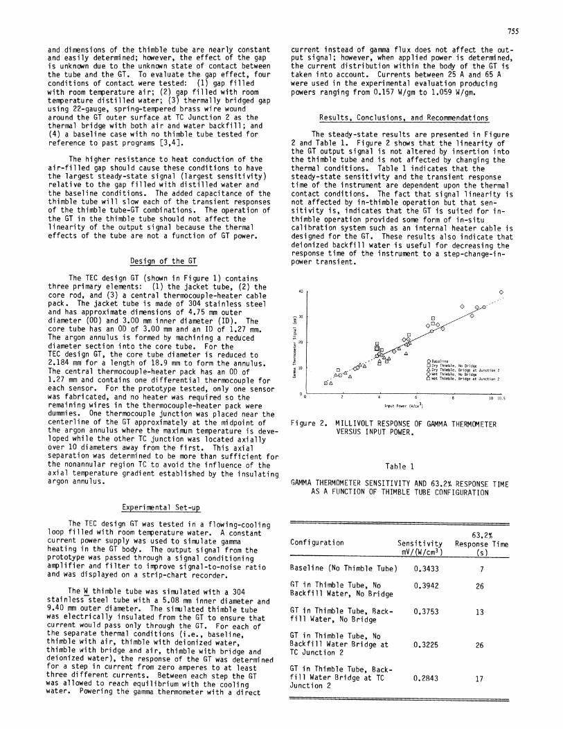
The steady-state results are presented in Figure2 and Table 1. Figure 2 shows that the linearity ofthe GT output signal is not altered by insertion intothe thimble tube and is not affected by changing thethermal conditions. Table 1 indicates that thesteady-state sensitivity and the transient responsetime of the instrument are dependent upon the thermalcontact conditions. The fact that signal linearity isnot affected by in-thimble operation but that sen-sitivity is, indicates that the GT is suited for in-thimble operation provided some form of in-situcalibration system such as an internal heater cable isdesigned for the GT. These results also indicate thatdeionized backfill water is useful for decreasing theresponse time of the instrument to a step-change-in-power transient.
40 P
-30
E
20
L
,% 10
0
0 Baseline0 Dry Thimble, No BridgeL Dry Thimble, Bridge at Junction 2oWet Thimble, No Bridge2 Wet Thimble, Bridge at Junction 2
GAMMA THERMOMETER SENSITIVITY AND 63.2% RESPONSE TIMEAS A FUNCTION OF THIMBLE TUBE CONFIGURATION
Experimental Set-up
The TEC design GT was tested in a flowing-coolingloop filled with room temperature water. A constantcurrent power supply was used to simulate gammaheating in the GT body. The output signal from theprototype was passed through a signal conditioningamplifier and filter to improve signal-to-noise ratioand was displayed on a strip-chart recorder.
The W thimble tube was simulated with a 304stainless steel tube with a 5.08 mm inner diameter and9.40 mm outer diameter. The simulated thimble tubewas electrically insulated from the GT to ensure thatcurrent would pass only through the GT. For each ofthe separate thermal conditions (i.e., baseline,thimble with air, thimble with deionized water,thimble with bridge and air, thimble with bridge anddeionized water), the response of the GT was determinedfor a step in current from zero amperes to at leastthree different currents. Between each step the GTwas allowed to reach equilibrium with the coolingwater. Powering the gamma thermometer with a direct
63.2%Configuration Sensitivity Response Time
mV/(W/cm3) (s)
Baseline (No Thimble Tube) 0.3433 7
GT in Thimble Tube, No 0.3942 26Backfill Water, No BridgeGT in Thimble Tube, Back- 0.3753 13fill Water, No BridgeGT in Thimble Tube, NoBackfill Water Bridge at 0.3225 26TC Junction 2
GT in Thimble Tube, Back-fill Water Bridge at TC 0.2843 17Junction 2
0 1
756
Future testing should concentrate on design ofthe in-situ calibration system and refinements to thethermal bridging concept. These refinements couldinclude design of thermal bridges with differentmaterials and different locations. Finally, in-coretests in actual thimble tubes should be conducted.
References
[1] J. P. Waring and R. D. Smith, "Recent ReactorTesting and Experience with Gamma Thermometers,"IEEE Trans., vol. NS-30, No. 1, February 1983.
[2] R. Leyse and R. D. Smith, "Gamma ThermometerDevelopment for Light Water Reactors," IEEE, vol.NS-26, No. 1, February 1979.
[3] F. E. LeVert and D. Bell, "Fabrication andElectric Calibration of Prototype PWR GammaThermometers," IEEE Trans., U.S., vol. NS-22,October 1981.
[4] R. L. Kress, A. H. Levin, and D. L. Bell, GammaThermometer Calibration and Testing DataSummary, TEC Report R-82-034, September 1982.