Testing of Carbon Filters in Australian Nuclear Installations Nuclear Installations 31 st International Nuclear Air Cleaning Conference, Charlotte NC 19-21July 2010 Luis Rudenas Engineering & Technical Services July 2010 Australian Nuclear Science and Technology Organisation
Transcript
Testing of Carbon Filters in Australian Nuclear InstallationsNuclear Installations
31st International Nuclear Air Cleaning Conference, Charlotte NC19-21July 20109 Ju y 0 0
Luis Rudenas Engineering & Technical Services
July 2010
Australian Nuclear Science and Technology Organisation
Carbon filter tests objectivesj• Prevent reactor shutdown due to carbon filter
failures • Trained workshop personnel available at any
time to refill carbon filters• Easy to understand instructions to test filters by
maintenance personnelNew filter housing upgrades with modular• New filter housing upgrades with modular designs of canisters and fire suppression
• Filtration system tested and reliable StackFiltration system tested and reliable. Stack monitoring to check effectiveness
July 2010
Adopted standards for assembling and testing filters at ANSTO
• ASME AG-1 Code on Nuclear Air and GasASME AG 1 Code on Nuclear Air and Gas Treatment
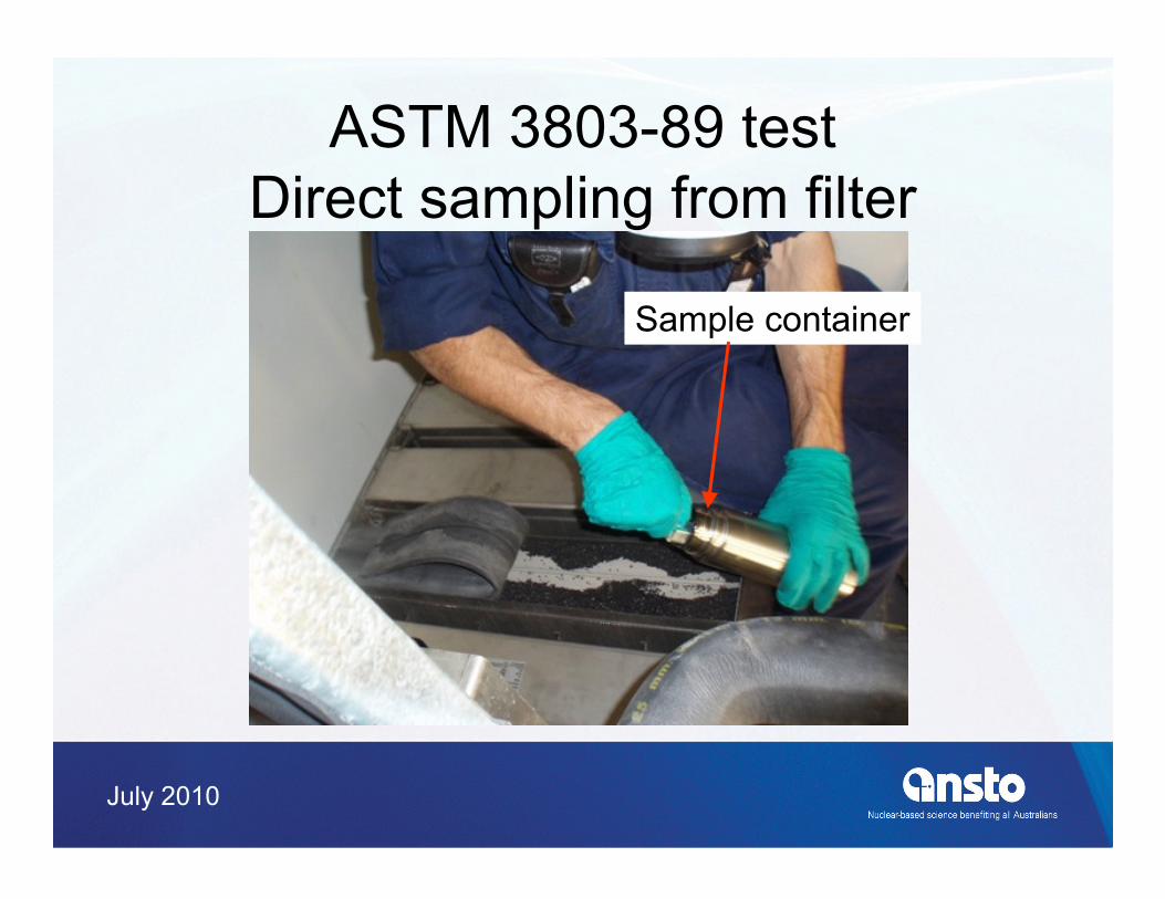
• ASTM 3803 89 Standard Test Method of• ASTM 3803-89 Standard Test Method of Nuclear-Grade Activated CarbonASME N510 2002 T ti f N l Ai• ASME N510 -2002 Testing of Nuclear Air Treatment Systems
• ASME N509-2002 Nuclear Power Plant Air-Cleaning Units and Components
July 2010
Test of carbon filtersI j ti d li if ld l• Injection and sampling manifolds properly designed
• Air distribution test• Air distribution test• Aerosol uniformity test• Mechanical integrity test pulses of 1Mechanical integrity test, pulses of 1
Bromobutane• Advantage of gas pulse is less gas used and g g p g
the test can be repeated immediately• Gas pulse test complemented by laboratory
t t f i t ll d i t b di t btest of installed canisters or by direct carbon sampling of filters
July 2010
Response to carbon test results• ASTM 3803-89 test failure requires carbon
filters to be replacedfilters to be replaced• Mechanical test failure requires filters to
be reinstalled or replacedbe reinstalled or replaced• Availability of carbon with valid ASTM
3803-89 Certificate (5 years)• Spare filters with valid certificate (5 years if
never used)
July 2010
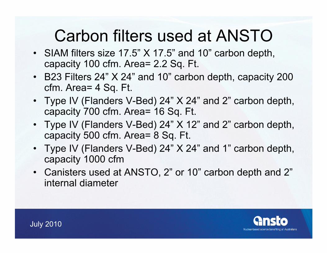
Carbon filters used at ANSTO• SIAM filters size 17.5” X 17.5” and 10” carbon depth,
capacity 100 cfm. Area= 2.2 Sq. Ft.• B23 Filters 24” X 24” and 10” carbon depth capacity 200B23 Filters 24 X 24 and 10 carbon depth, capacity 200
cfm. Area= 4 Sq. Ft.• Type IV (Flanders V-Bed) 24” X 24” and 2” carbon depth,
capacity 700 cfm Area= 16 Sq Ftcapacity 700 cfm. Area= 16 Sq. Ft.• Type IV (Flanders V-Bed) 24” X 12” and 2” carbon depth,
capacity 500 cfm. Area= 8 Sq. Ft.• Type IV (Flanders V-Bed) 24” X 24” and 1” carbon depth,
capacity 1000 cfm• Canisters used at ANSTO 2” or 10” carbon depth and 2”Canisters used at ANSTO, 2 or 10 carbon depth and 2
internal diameter
July 2010
Carbon filter ready for refilling
Welded ScrewWelded Screw
July 2010
Facility to assemble filtersCarbon HopperExtract Ventilation
Instruments for carbon testingg• NUCON Model HGPH Pulse Mode Halide
GeneratorGenerator• NUCON Model F-2000-HD ppm and ppb halide
detector• NUCON Model F-2000-BBD ppb halide detector• NUCON Model F-1000-CR calibration rig to
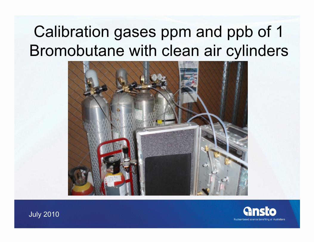
lib t th h lid d t tcalibrate the halide detectors• Calibration gases 200 ppb and 36 ppm of 1
Bromobutane with corresponding clean airBromobutane with corresponding clean air cylinders supplied by NUCON.
July 2010
TestingTesting set up Portable fan assembly50 mm ID hose
Injectionmanifold
From building exhaust
Pulse gas generator
arrangementPortable HEPA filter/ fan assembly
manifold
Carbon filter
Upstream samplingmanifold
ExhaustIn
ppm Halide detectorunder test
Exhaust
outputs In
ppmppb
Halide detector
Halide detector
P t bl HEPA filt / f bl
Downstreamsamplingmanifold
Portable HEPA filter/ fan assemblyFan
July 2010
Halide injection pulse testj• 1 ml of liquid 1 Bromobutane is equivalent to
223.8 ml of gas at 20 oC2238 L/ f i fl h 100 f 1• 2238 L/s of air flow has 100 ppm of 1 Bromobutane gas when 1 ml of liquid is injected in one second
• Always measure upstream concentration to ensure proper gas injection and calculate penetration. Penetration = 100*Cd/Cupenetration. Penetration 100 Cd/Cu
• Maximum allowed penetration at ANSTO is 1%• The downstream concentration may exceed the
i t t h th b filt l kinstrument range when the carbon filter leaks
July 2010
Copper testing manifold
July 2010
Fitting 2” BSP of internal diameterto be pop riveted to a duct
July 2010
Installing the testing manifold
July 2010
Calibration gases ppm and ppb of 1 B b i h l i li dBromobutane with clean air cylinders
July 2010
Gas detectors ppm and ppb
July 2010
Gas leak investigation in a side bl l t f filtremovable plate of a new filter
tane
omob
ut
Injection time
of 1
Bro
ppb
0 1 2 3 4 5 6 7
Time in minutes
July 2010
Carbon filter housing requirements• Canisters for surveillance testing
I j ti d li if ld• Injection and sampling manifolds• Inlet and outlet plenums• Fire suppression
– Bubble tight dampers to isolate filters in case g pof fire or for maintenance purposes
– Carbon Monoxide sensors– Thermocouples
July 2010
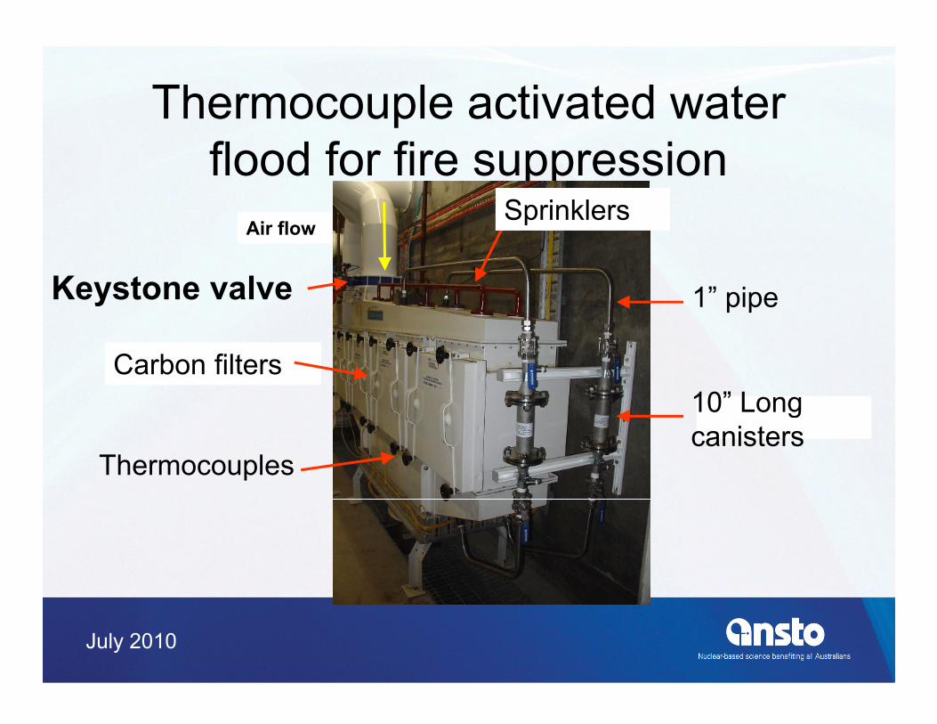
Thermocouple activated water flood for fire suppression
SprinklersAir flow
p
1” pipeKeystone valve
Air flow
10” LongCarbon filters
10 Long canisters
Thermocouples
July 2010
Fire suppression for CyclotronThermocouples
HEPA filtersCanisters Air flow
CO Sensors
C b filtCarbon filters
Keystone Valve
July 2010
Fire suppression for Hot CellsKeystone ValvesValve
Air flow Canistersactuator
HEPA filters
Thermocouples
CO Sensor
Carbon filters
July 2010
Fire suppression panelCO and type K thermocouples
CO MonitorCO Monitor
Thermocouple displays
July 2010
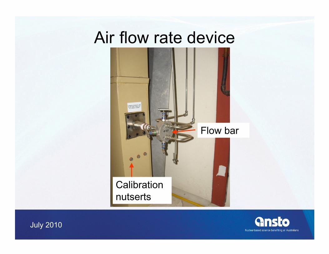
Stack monitoring• Air flow rate monitoring using Flow Bar
devicesdevices• Off-line weekly monitoring using TC45
carbon cartridges for gases and Whatmancarbon cartridges for gases and Whatman filter papers for particulatesR l ti it i f bl i• Real time monitoring for noble gases using NaI sensors and a Canberra Lynx multi-h l lchannel analyser
July 2010
Equipment for stack monitoring
Pressurel
NaI sensor alarm
Flowmeter Flow signalStack sample line
Computer100 mLAl container
Stack air flow rate
Lynx MCA
Motor
Air flow 5 L/min
Pump
Return line to stack
Temperaturecontrolled cabinet
July 2010
Air flow rate device
Flow bar
Calibration nutserts
July 2010
Display of stack flow
Alarm pressure switch
FlowFlow display
July 2010
Stack sampling
TC45 & filter paper Samplingp pweekly sampler
Sampling lines for real time
Pitot tubePitot tube
July 2010
Performance of TC45 carbon cartridgesTC45
H3I
%
TC30ency
CH
TC30
n E
ffici
e
TC12
eten
tion
R
Flow Rate (SCFM)Reproduced from
HiQ data
July 2010
Operating System Platform Independent Real-time Monitor
Top view of NaI sensorsfor real time stack monitoring
NaI sensor
Shielding for sensors
July 2010
Cabinet for stack monitoringgComputer
Lynx
UPS
Lynx Canberra MCA
Shielded NaI sensor
July 2010
Real timestack monitoring display
Gamma Spectr mSpectrum0-2000 keV
July 2010
Conclusions• Correctly design new filter housings with
canisters testing manifolds bubble tightcanisters, testing manifolds, bubble tight dampers and CO monitors
• Periodically test the carbon filters and be• Periodically test the carbon filters and be prepared for filter changes at any timeM it filt f ith t d f• Monitor filter performance with trends of weekly and real time releases through the t kstacks