Page 1
TESTING OF UNIFIED POWER FLOW CONTROLLER ( UPFC ) MODEL IN IEEE 9 BUS
POWER SYSTEM NETWORK USING
PSCAD/EMTDC AND MATLAB SOFTWARE
NUR AZIRA BINTI MOHD SALEH
This thesis is submitted as partial fulfillment of the requirements for the award of
the Bachelor of Electrical Engineering (Power System)
Faculty of Electrical & Electronics Engineering
University Malaysia Pahang
NOVEMBER 2010
Page 2
ii
“All the trademark and copyrights use herein are property of their respective owner.
References of information from other sources are quoted accordingly; otherwise the
information presented in this report is solely work of the author.”
Signature : ____________________________
Author : NUR AZIRA BINTI MOHD SALEH
Date : 11 NOVEMBER 2010
Page 3
iv
ACKNOWLEDGEMENTS
In the name of Allah s.w.t., most gracious, most merciful.
Firstly, I would like to thank my project supervisor, Miss Lailatul Niza Binti
Muhammad for her never ending guidance and support that she given to me in
completing this project.
Secondly, I would like to thank to my beloved family members for their loves
and support throughout my studies in University Malaysia Pahang (UMP). For their
constant support and encouragement, helps me to keep going despite all the challenges I
face here.
Special thanks and gratitude to all the FKEE staff who have given me a great
help in completing this project. Last but not least, I would like to say thanks to all of my
friends and those who help me in this project.
May God repay all of your kindness.
Page 4
v
ABSTRACT
Unified Power Flow Controller (UPFC) is the most widely used Flexible ac
Transmission system ( FACTS ) device to control the power flow and to optimize the
system stability in the transmission line. It should be installed to control the voltage, as
well as to control the active and reactive power flow through the transmission line. This
project is using PSCAD/EMTDC and MATLAB software to model and to verify the
UPFC system in order to improve its performance in power system. MATPOWER in
MATLAB software used to run the power flow of IEEE 9 bus power system network.
Then, by using PSCAD/EMTDC software, IEEE 9 bus system was designed and the
result of power flow 9 bus system using PSCAD/EMTDC was compared with the power
flow in MATPOWER. The result of active power, P (MW) , reactive power ,Q (MVar)
and power loss were compared to make sure that both software have the similar answer
with only 1% difference. The power flow in both softwares must be similar before
injecting the UPFC system. Then, the active power and reactive power performance will
be improved due to injecting the UPFC device. Stability and transient performance of
active and reactive power was analyzed.
Page 5
vi
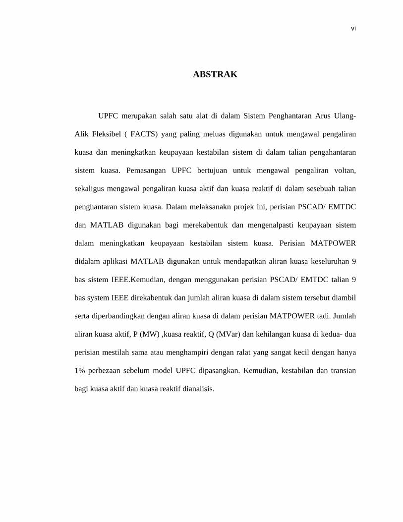
ABSTRAK
UPFC merupakan salah satu alat di dalam Sistem Penghantaran Arus Ulang-
Alik Fleksibel ( FACTS) yang paling meluas digunakan untuk mengawal pengaliran
kuasa dan meningkatkan keupayaan kestabilan sistem di dalam talian pengahantaran
sistem kuasa. Pemasangan UPFC bertujuan untuk mengawal pengaliran voltan,
sekaligus mengawal pengaliran kuasa aktif dan kuasa reaktif di dalam sesebuah talian
penghantaran sistem kuasa. Dalam melaksanakn projek ini, perisian PSCAD/ EMTDC
dan MATLAB digunakan bagi merekabentuk dan mengenalpasti keupayaan sistem
dalam meningkatkan keupayaan kestabilan sistem kuasa. Perisian MATPOWER
didalam aplikasi MATLAB digunakan untuk mendapatkan aliran kuasa keseluruhan 9
bas sistem IEEE.Kemudian, dengan menggunakan perisian PSCAD/ EMTDC talian 9
bas system IEEE direkabentuk dan jumlah aliran kuasa di dalam sistem tersebut diambil
serta diperbandingkan dengan aliran kuasa di dalam perisian MATPOWER tadi. Jumlah
aliran kuasa aktif, P (MW) ,kuasa reaktif, Q (MVar) dan kehilangan kuasa di kedua- dua
perisian mestilah sama atau menghampiri dengan ralat yang sangat kecil dengan hanya
1% perbezaan sebelum model UPFC dipasangkan. Kemudian, kestabilan dan transian
bagi kuasa aktif dan kuasa reaktif dianalisis.
Page 6
vii
TABLE OF CONTENTS
CHAPTER TITLE PAGE
Declaration ii
Dedication iii
Acknowledgement iv
Abstract v
Abstrak vi
Table of Contents vii
List of Tables x
List of Figures xii
List of Abbreviations xv
List of appendices xvi
1.0 INTRODUCTION
1.1 Introduction 1
1.2 Problem statement 2
1.3 Objectives 2 1.4 Scope of work 3
1.5 Outline thesis 3
Page 7
viii
2.0 LITERATURE REVIEW
2.1 Unified Power Flow Controller (UPFC) 5 2.2 Mathematical model of UPFC 10 2.3 Summary 13
3.0 METHODOLOGY
3.1 Introduction 14
3.2 Software 14
3.2.1 PSCAD/EMTDC 14
3.2.2 MATLAB 18
3.2.2. 1 Key features 19
3.2.3 MATPOWER 19
3.3 Flow Chart 20
3.4 Simulation Design Using PSCAD/EMTDC 24
3.4.1 Shunt Inverter Control Circuit 25
3.4.2 Series Inverter Control Circuit 26
3.5 Summary 27
Page 8
ix
4.0 RESULTS AND DISCUSSION 4.1 Introduction 28
4.2 Simulation in PSCAD/EMTDC 28
4.3 Simulation of Testing Bus 29
( IEEE 4 bus system)
4.3.1 Bus Data 30
4.3.2 Generator Data 30
4.3.3 Branch Data 31
4.4 Simulation of UPFC for IEEE 34
9 bus System
4.4.1 Bus Data 35
4.4.2 Generator Data 36
4.4.3 Branch Data 36
4.5 Testing IEEE 9bus System with UPFC 40
4.6 Results 51
4.6 Summary 52
5.0 CONCLUSION 5.1 Conclusion 53 5.2 Future recommendation 54
REFFERENCE 55
Page 9
x
LIST OF TABLES
TABLE NO. TITLE PAGE
4.11 MVA base and V base for 4 bus system 29
4.12 Bus data of IEEE 4 bus system 30
4.13 Generator data of IEEE 4 bus system 31
4.14 Branch data of IEEE 4 bus system 31
4.15 Impedance of 4 bus system in actual 32
4.16 Voltage magnitude and phase angle of 32
MATPOWER power flow
4.17 Power flow data from MATPOWER software 33
4.18 Power flow data from PSCAD software 33
4.19 Comparison of power loss between PSCAD 33
And MATPOWER software
4.20 MVA base and Vbase for 9 bus system 35
4.21 Bus data of IEEE 9 bus system 35
4.22 Generator data of IEEE 9 bus system 36
4.23 Branch data of IEEE 9 bus system 37
4.24 Impedance of 9 bus system in actual 38
4.25 Voltage magnitude and phase angle from 38
MATPOWER power flow
4.26 Power flow result from MATPOWER for 9 bus 39
System
Page 10
xi
4.27 Power flow result from PSCAD for 9 bus system 39
4.28 Comparison of power loss between PSCAD and 40
MATPOWER software
Page 11
xii
LIST OF FIGURES
FIGURE NO. TITLE PAGE
2.1 Schematic of UPFC 6
2.2 Schematic diagram of the 3 phase UPFC 7
connected to the transmission line
2.3 Single line diagram of UPFC and phasor 8
Diagram of voltage and current
3.1 Master library of PSCAD/EMTDC software 17
3.2 MATLAB software 18
3.3 Example of M-File window (MATPOWER) 20
3.4 Flow chart for the whole project 21
3.5 Flow chart for the simulation 23
3.6 Power system study model 24
3.7 Circuit of UPFC using GTO 25
3.8 Voltage control for shunt inverter (STATCOM) 26
3.9 Voltage control for series inverter (SSSC) 29
4.1 IEEE 4 bus testing system using PSCAD/EMTDC 31
4.2 IEEE 9 bus testing system using PSCAD/EMTDC 34
4.3 IEEE 9 bus system with UPFC 41
Page 12
xiii
4.4 Performance of active power (P) at line 9-8 before 42
Injecting UPFC
4.5 Performance of reactive power (Q) at line 9-8 before 42
Injecting UPFC
4.6 Performance of active power (P) at line 4-1 before 43
Injecting UPFC
4.7 Performance of reactive power (Q) at line 4-1 before 43
Injecting UPFC
4.8 Performance of active power (P) at line 5-4 before 44
Injecting UPFC
4.9 Performance of reactive power (Q) at line 5-4 before 44
Injecting UPFC
5.0 Performance of active power (P) at line 6-5 before 45
Injecting UPFC
5.1 Performance of reactive power (Q) at line 6-5 before 45
Injecting UPFC
5.2 Performance of active power (P) at line 7-6 before 46
Injecting UPFC
5.3 Performance of reactive power (Q) at line 7-6 before 46
Injecting UPFC
5.4 Performance of active power (P) at line 8-7 before 47
Injecting UPFC
5.5 Performance of reactive power (Q) at line 8-7 before 47
Injecting UPFC
Page 13
xiv
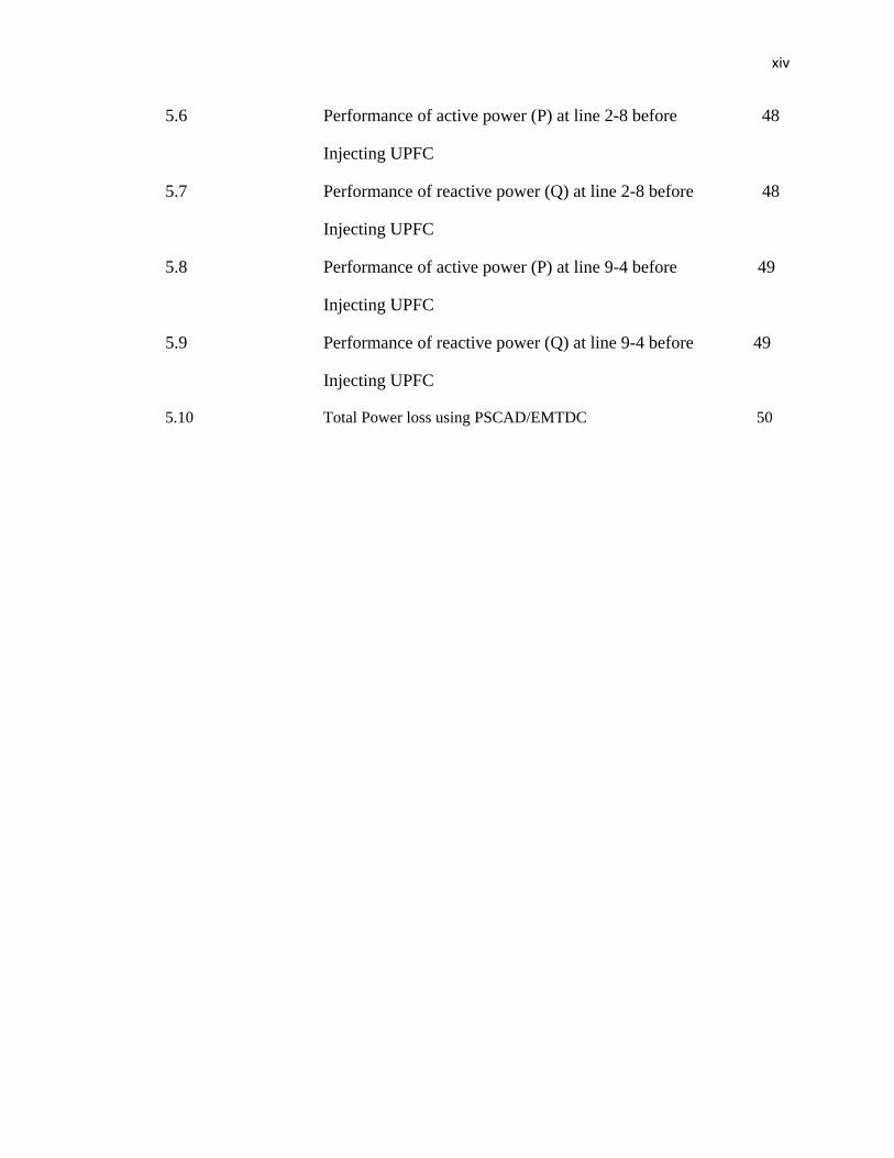
5.6 Performance of active power (P) at line 2-8 before 48
Injecting UPFC
5.7 Performance of reactive power (Q) at line 2-8 before 48
Injecting UPFC
5.8 Performance of active power (P) at line 9-4 before 49
Injecting UPFC
5.9 Performance of reactive power (Q) at line 9-4 before 49
Injecting UPFC
5.10 Total Power loss using PSCAD/EMTDC 50
Page 14
xv
LIST OF ABBREVIATIONS
AC Alternating Current
EMTDC Electromagnetic Transient Direct Current
GTO Gate Turn Off
IEEE The Institute of Electrical and Electronics Engineers
IGBT Insulated Gate Bipolar Transistor
MATLAB Matrix Laboratory
P Active power
PLL Phase Locked Loop
PSCAD Power System Computer Aided Design
p.u. Per-unit
SPWM Sinusoidal Pulse Width Modulation
Q Reactive power
SSSC Series Synchronous Compensator
STATCOM Static Synchronous Compensator
VSC Voltage-sourced Converter
Page 15
xvi
LIST OF APPENDICES
APPENDIX NO. TITLE PAGE
A Power Flow 4 bus Solution by Newton’s Method 58 B Power Flow 9 bus Solution by Newton’s Method 61
Page 16
CHAPTER 1
INTRODUCTION
1.1 Introduction
Unified Power Flow Controller ( UPFC ) is the universal and most flexible
FACTS (Flexible ac Transmission System). It is used to control the power flow in the
transmission systems by controlling the impedance, voltage magnitude and phase angle.
This device can allow the path of power as we desire. UPFC consist of two Voltage
Supply Inverters, one series converter and one shunt converter. This device is actually a
combination of two FACTs device which are STATCOM (Static Synchronous
Compensator) and SSSC (Static Series Synchronous Compensator). SSSC is used to add
controlled voltage magnitude and phase angle in series with the line, while shunt
converter STATCOM is used to provide reactive power to the ac system, beside that, it
will provide the dc power required for both inverter [1]. The reactive power can be
compensated either by improving the receiving voltage or by reducing the line reactance
[2].
Page 17
2
UPFC should be installed to control the voltage, as well as to control the active
and reactive power flow through the transmission line. However, the right transmission
line to be injected by UPFC and the effect of injection will only know by doing the
analysis using MATLAB and PSCAD software.
Thus, this project presents the active and reactive power control through a
transmission line by placing the UPFC using computer simulation. PSCAD and
MATLAB program are used to model and to verify the performance of UPFC in order to
increase the ability of the system.
1.2 Problem statement
Unified Power Flow Controller (UPFC) is the most widely used Flexible ac
Transmission system ( FACTS ) device to control the power flow and to optimize the
system stability in the transmission line. It should be installed to control the voltage, as
well as to control the active and reactive power flow through the transmission line.
1.3 Objectives
The objectives of this project are to:
i. simulate IEEE 9 bus power system network using PSCAD software and
comparing with MATLAB power flow result.
ii. model UPFC in IEEE 9 bus power system network sample and determine the
most efficient transmission line to be injected.
iii. analyze the steady-state analysis of the 9 bus power system network before
and after UPFC applied.
Page 18
3
1.4 Scope of Work
The scopes of this project are:
i. modeling UPFC in IEEE 9 bus power system network.
ii. simulation on the IEEE 9 bus power system network power flow using
MATLAB and PSCAD software.
iii. analyze and compare the performance of 9 bus system before and after UPFC
applied.
1.5 Outline thesis
For the thesis outline, the progress elements are divided into chapters and the
details are as follows:
i. Chapter 1
This chapter consists of introduction, objectives, scope of work and thesis
outline. In introduction, the problem statement is stated here along with the
relevant solution. It’s to support the main objectives and the relevancy of the
proposed title. In the objectives, the goal of the project is stated in here. It’s
consists of the aim that must be achieved at the end of the project. In the scope of
work, the detailed work flow stated in here. This step by step flow work is to
keep the project’s progress on track and to meet the objective. Lastly in thesis
outline, the overall elements needed in the thesis are stated.
Page 19
4
ii. Chapter 2
Chapter 2 is about literature review. It is the study on the others papers,
journal, website citation and other dependable sources that related to the project.
Literature review is crucial for every thesis not only to support the proposed title
but also for guidelines and references on the conducted thesis.
iii. Chapter 3
Chapter 3 explains the methodology of the project. It is to describe in
details about the scope of project. In this part, every step on how to approach the
solutions to overcome the stated problems is described in details. It shows how
the work will be done. The details such as flow chart and schematic diagram are
shown in here.
iv. Chapter 4
Chapter 4 is about result and discussions. In this chapter, all the finding
related to the project is stated in here. Every output produce from the project are
stated, analyzed and explained briefly.
v. Chapter 5
This chapter consists of conclusion and future recommendations section.
In the conclusion, the project’s objectives and achieved result are concluded. In
future recommendations, the suggestions to improve the existed project are
stated.
Page 20
CHAPTER 2
LITERATURE REVIEW
2.1 Unified Power Flow Controller ( UPFC )
The cost of losing synchronous through a transient instability is extremely high
in modern power systems. Consequently, utility engineers often perform a large number
of stability studies in order to avoid this problem. A unified power flow controller
(UPFC) is the most promising device in the FACTS concept. It has the ability to adjust
the three control parameters such as the bus voltage, transmission line reactance, and
phase angle between two buses, either simultaneously or independently. A UPFC
performs this through the control of the in-phase voltage, quadrature voltage, and shunt
compensation. UPFC can control the three control parameters either individually or in
appropriate combinations at its series-connected output while maintaining reactive
power support at its shunt-connected input. The mechanism of the three control methods
of a UPFC in enhancing power system damping. It was shown that a significant
reduction in the transient swing can be obtained by using a simple proportional feedback
of machine rotor angle deviation. It is generally accepted that the addition of a
supplementary controller to the UPFC can significantly enhance power system damping
[3].
Page 21
b
p
c
c
s
s
b
e
c
s
p
f
The m
by injecting
phase angle
control can
closer to the
stability of th
The
source conve
branch of th
exchange re
capacitor is
should be e
power in th
flexibility to
main functio
of a voltage
of the volta
allow for th
eir thermal li
he power sy
UPFC cons
erter which
he UPFC can
al power wi
generally s
equal to the
he shunt or
o the power f
on of the UP
e in series wi
age can be v
e power flow
imits and can
ystem. The sc
Figu
sists of two
injects a vol
n inject a vol
ith the trans
small. There
active pow
series conv
flow control
PFC is to con
ith the transm
varied indep
w in prescrib
n be utilized
chematic of
re 2.1 : Schem
branches. T
ltage in serie
ltage with va
mission line
efore, active
wer generate
verter can b
.
ntrol the flo
mission line
pendently. R
bed routes, l
d for improvi
the UPFC is
matic of the U
The series b
es through a
ariable magn
e. The energ
e power dra
d by the se
be chosen in
w of real an
. Both the m
Real and reac
loading of tr
ing transient
s shown in F
UPFC
branch cons
transformer
nitude and p
gy storing ca
awn by the
eries convert
ndependently
nd reactive p
magnitude an
ctive power
ransmission
t and small s
Figure 2.1.
ists of a vo
r. Since the s
phase angle i
apacity of th
shunt conv
ter. The rea
y, giving gr
6
power
nd the
flow
lines
signal
oltage
series
it can
his dc
verter
active
reater
Page 22
s
l
F
a
d
l
a
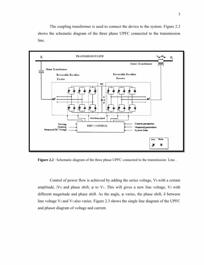
The
shows the s
line.
Figure 2.2 : S
Cont
amplitude, |V
different ma
line voltage
and phasor d
coupling tra
chematic di
Schematic dia
trol of power
VS| and pha
agnitude and
V2 and V3 al
diagram of v
ansformer is
agram of th
agram of the t
r flow is ach
ase shift, φ t
d phase shift
lso varies. F
voltage and c
used to con
he three pha
three phase U
hieved by ad
to V1. This
t. As the ang
Figure 2.3 sh
current.
nect the dev
ase UPFC co
UPFC connect
dding the ser
will gives
gle, φ varies
hows the sing
vice to the sy
onnected to
ted to the tran
ries voltage,
a new line
s, the phase
gle line diagr
ystem. Figur
the transmi
nsmission Lin
VS with a ce
voltage, V2
shift, δ bet
ram of the U
7
re 2.2
ission
ne .
ertain
with
tween
UPFC
Page 23
s
p
t
p
a
e
b
c
b
Figur
How
steady state
power sourc
the system)
power balan
addition to
exchange re
based FACT
capabilities o
but also to im
re 2.3: Single
wever the UP
(except for
ce at its DC t
for any real
nce is not m
maintaining
active powe
TS controlle
of the UPFC
mprove stabi
e line diagram
PFC as a co
the power
terminals. Th
power draw
maintained, th
g the real po
er with the sy
ers over me
C need to be
ility.
m of UPFC an
ompensator
drawn to co
hus the shun
wn/ supplied b
he capacitor
ower balanc
ystem. The m
echanical co
exploited n
nd phasor diag
cannot supp
ompensate fo
nt branch is r
by the series
r cannot rem
ce, the shun
main advant
ontrollers is
ot only for s
gram of voltag
ply or absor
or the losses
required to c
s branch and
main at a con
nt branch ca
tage of the p
s their speed
steady state l
ge and curren
rb real pow
s) unless it h
compensate (
d the losses. I
nstant voltag
an independ
power electr
d. Therefore
load flow co
8
nt
wer in
has a
(from
If the
ge. In
dently
ronics
e the
ontrol
Page 24
9
However it is not obvious as to how to use the series voltage and shunt current
(subject to the power balance constraint) for UPFC control. In this context it is suitable
to control the strategies and controller design to achieve the same is of importance [4].
The UPFC has many possible operating modes. In particular, the shunt inverter
is operating in such a way to inject a controllable current, ish into the transmission line.
The shunt inverter can be controlled in two different modes [5]:
i. VAR Control Mode: The reference input is an inductive or capacitive
VAR request. The shunt inverter control translates the Var reference into
a corresponding shunt current request and adjusts gate of the inverter to
establish the desired current. For this mode of control a feedback signal
representing the dc bus voltage, Vdc, is also required.
ii. Automatic Voltage Control Mode: The shunt inverter reactive current is
automatically regulated to maintain the transmission line voltage at the
point of connection to a reference value. For this mode of control, voltage
feedback signals are obtained from the sending end bus feeding the shunt
coupling transformer. The series inverter controls the magnitude and
angle of the voltage injected in series with the line to influence the power
flow on the line. The actual value of the injected voltage can be obtained
in several ways.
iii. Direct Voltage Injection Mode: The reference inputs are directly the
magnitude and phase angle of the series voltage.
iv. Phase Angle Shifter Emulation mode: The reference input is phase
displacement between the sending end voltage and the receiving end
voltage.