24
Testing Parity Testing Parity - - Based Error Based Error Detection and Correction Detection and Correction Circuits Circuits Charles E. Stroud Charles E. Stroud
| Date post: | 06-Mar-2018 |
| Category: |
Documents |
| Upload: | truongxuyen |
| View: | 227 times |
| Download: | 0 times |
Testing ParityTesting Parity--Based Error Based Error Detection and Correction Detection and Correction
CircuitsCircuits
Charles E. StroudCharles E. Stroud
C. Stroud 9/6/06 VLSI Design & Test Seminar 2
Outline of PresentationOutline of PresentationTesting ExclusiveTesting Exclusive--OR (XOR) GatesOR (XOR) Gates
Pin faults vs. gatePin faults vs. gate--level faultslevel faultsParity CircuitsParity Circuits
Basic operation and designBasic operation and designTesting parity treesTesting parity trees
CC--testable for known connectionstestable for known connectionsPseudoPseudo--exhaustive test set for unknown connectionsexhaustive test set for unknown connections
StuckStuck--at & bridging fault simulation results using AUSIMat & bridging fault simulation results using AUSIM
Hamming CircuitsHamming CircuitsBasic operation and designBasic operation and design
Use in Use in FPGAsFPGAsPseudoPseudo--exhaustive test set for unknown connectionsexhaustive test set for unknown connections
StuckStuck--at & bridging fault simulation results using AUSIMat & bridging fault simulation results using AUSIM
Summary and ConclusionsSummary and Conclusions
C. Stroud 9/6/06 VLSI Design & Test Seminar 3
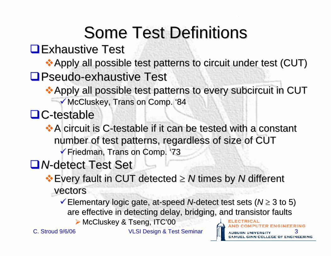
Some Test DefinitionsSome Test DefinitionsExhaustive TestExhaustive Test
Apply all possible test patterns to circuit under test (CUT)Apply all possible test patterns to circuit under test (CUT)PseudoPseudo--exhaustive Testexhaustive Test
Apply all possible test patterns to every Apply all possible test patterns to every subcircuitsubcircuit in CUTin CUTMcCluskeyMcCluskey, Trans on Comp. , Trans on Comp. ‘‘8484
CC--testabletestableA circuit is CA circuit is C--testable if it can be tested with a constant testable if it can be tested with a constant number of test patterns, regardless of size of CUTnumber of test patterns, regardless of size of CUT
Friedman, Trans on Comp. Friedman, Trans on Comp. ‘‘7373
NN--detect Test Setdetect Test SetEvery fault in CUT detected Every fault in CUT detected ≥≥ NN times by times by NN different different vectorsvectors
Elementary logic gate, atElementary logic gate, at--speed speed NN--detect test sets (detect test sets (NN ≥≥ 3 to 5) 3 to 5) are effective in detecting delay, bridging, and transistor faultare effective in detecting delay, bridging, and transistor faultss
McCluskeyMcCluskey & Tseng, ITC& Tseng, ITC’’0000
C. Stroud 9/6/06 VLSI Design & Test Seminar 4
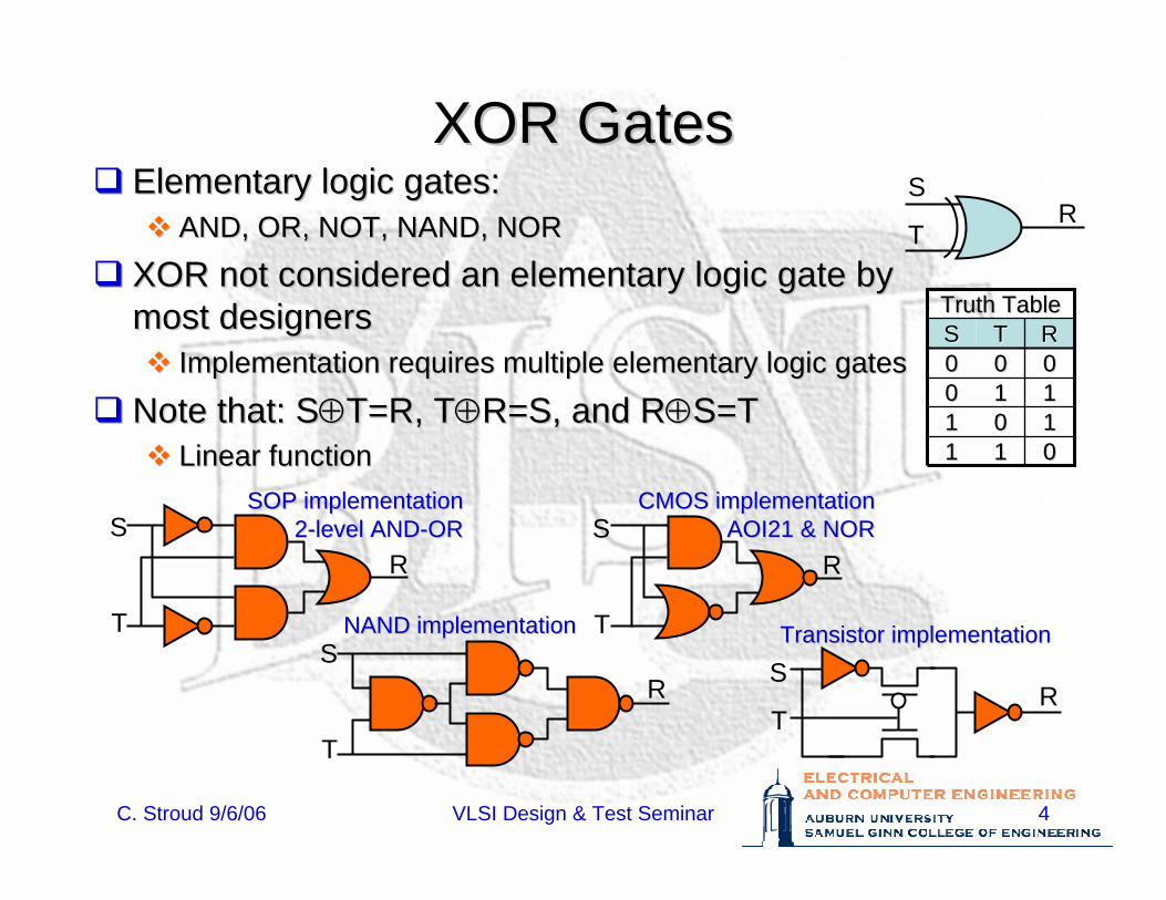
XOR GatesXOR GatesElementary logic gates:Elementary logic gates:
AND, OR, NOT, NAND, NORAND, OR, NOT, NAND, NOR
XOR not considered an elementary logic gate by XOR not considered an elementary logic gate by most designersmost designers
Implementation requires multiple elementary logic gatesImplementation requires multiple elementary logic gates
Note that: SNote that: S⊕⊕T=R, TT=R, T⊕⊕R=S, and RR=S, and R⊕⊕S=TS=TLinear functionLinear function
S
TR
Truth TableTruth Table
00111100RR
1111001111000000TTSS
S
T
R
SOP implementationSOP implementation22--level ANDlevel AND--OROR
S
T
R
NAND implementationNAND implementation
S
T
R
CMOS implementationCMOS implementationAOI21 & NORAOI21 & NOR
S
TR
Transistor implementationTransistor implementation
C. Stroud 9/6/06 VLSI Design & Test Seminar 5
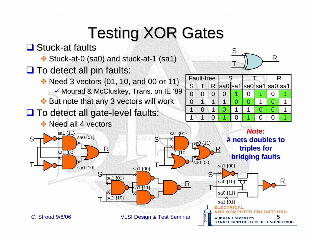
Testing XOR GatesTesting XOR GatesStuckStuck--at faultsat faults
StuckStuck--atat--0 (sa0) and stuck0 (sa0) and stuck--atat--1 (sa1)1 (sa1)To detect all pin faults:To detect all pin faults:
Need 3 vectors {01, 10, and 00 or 11}Need 3 vectors {01, 10, and 00 or 11}MouradMourad & & McCluskeyMcCluskey, Trans. on IE , Trans. on IE ‘‘8989
But note that any 3 vectors will workBut note that any 3 vectors will workTo detect all gateTo detect all gate--level faults:level faults:
Need all 4 vectorsNeed all 4 vectors
S
TR
RRTTSSFaultFault--freefree
00111100RR
11001100
sa0sa0
00110011
sa1sa1
11110000
sa0sa0
00001111
sa1sa1
00000000
sa0sa0
111111110011111100110000
sa1sa1TTSS
S
T
R
S
T
R
S
T
R
S
TR
sa1 {11}X
sa1 {00}X
sa0 {01}X
Xsa0 {10} sa1 {00}
Xsa1 {01}X
Xsa1 {10}
sa1 {11}X
sa0 {11}X
Xsa0 {00}
sa1 {01}X
Xsa1 {10}
sa0 {11}X
sa1 {01}
sa1 {00}
X
sa0 {10}
NoteNote::# nets doubles to # nets doubles to
triples fortriples forbridging faultsbridging faults
C. Stroud 9/6/06 VLSI Design & Test Seminar 6
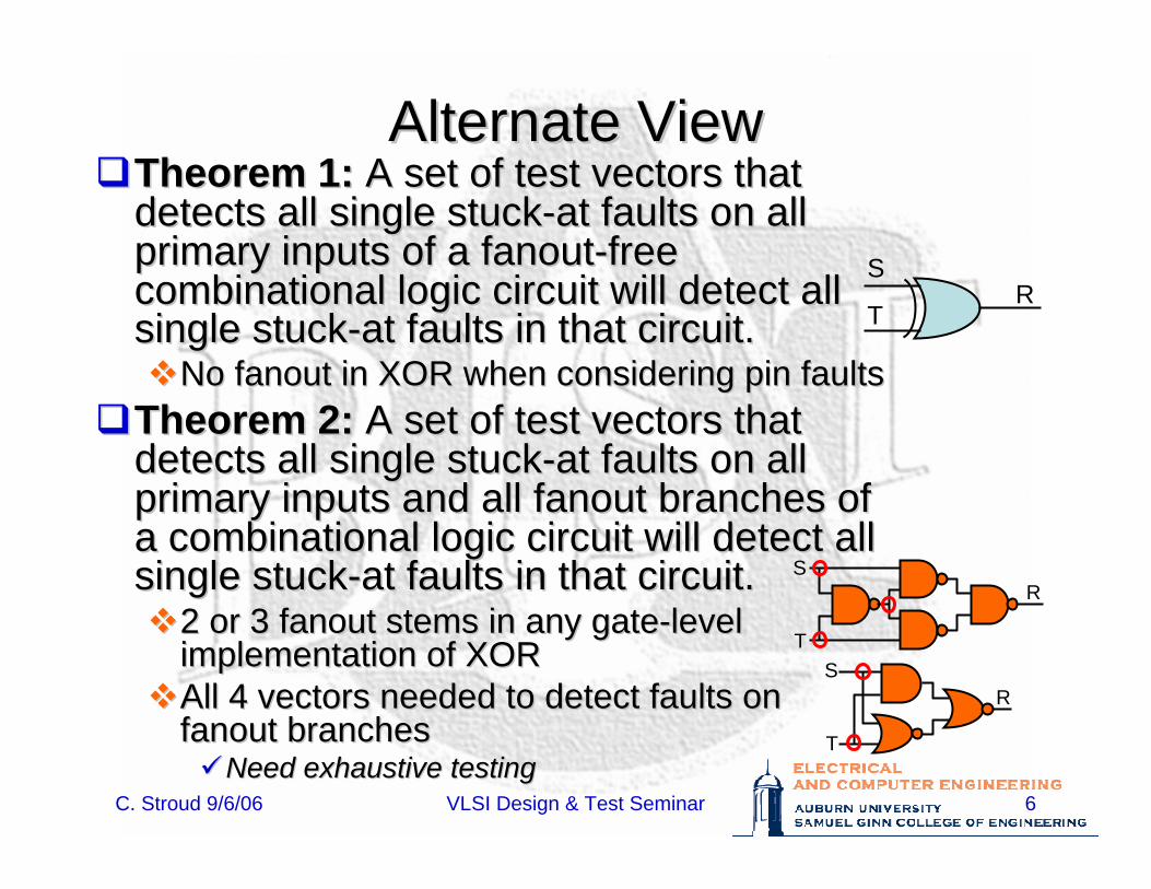
Alternate ViewAlternate ViewTheorem 1:Theorem 1: A set of test vectors that A set of test vectors that detects all single stuckdetects all single stuck--at faults on all at faults on all primary inputs of a primary inputs of a fanoutfanout--free free combinational logic circuit will detect all combinational logic circuit will detect all single stucksingle stuck--at faults in that circuit.at faults in that circuit.
No No fanoutfanout in XOR when considering pin faultsin XOR when considering pin faultsTheorem 2:Theorem 2: A set of test vectors that A set of test vectors that detects all single stuckdetects all single stuck--at faults on all at faults on all primary inputs and all primary inputs and all fanoutfanout branches of branches of a combinational logic circuit will detect all a combinational logic circuit will detect all single stucksingle stuck--at faults in that circuit.at faults in that circuit.
2 or 3 2 or 3 fanoutfanout stems in any gatestems in any gate--level level implementation of XORimplementation of XORAll 4 vectors needed to detect faults on All 4 vectors needed to detect faults on fanoutfanout branchesbranches
Need exhaustive testingNeed exhaustive testing
S
TR
S
T
R
S
T
R
C. Stroud 9/6/06 VLSI Design & Test Seminar 7
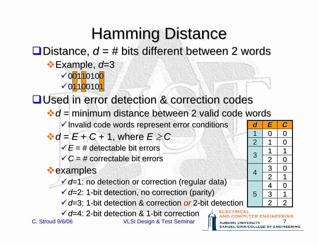
Hamming DistanceHamming DistanceDistance, Distance, dd = # bits different between 2 words= # bits different between 2 words
Example, Example, dd=3=300110100001101000110010101100101
Used in error detection & correction codesUsed in error detection & correction codesd d = minimum distance between 2 valid code words= minimum distance between 2 valid code words
Invalid code words represent error conditionsInvalid code words represent error conditionsd d = = E E + + C C + 1, where + 1, where E E ≥≥ CC
EE = # detectable bit errors= # detectable bit errorsC C = # correctable bit errors= # correctable bit errors
examplesexamplesdd=1: no detection or correction (regular data)=1: no detection or correction (regular data)dd=2: 1=2: 1--bit detection, no correction (parity)bit detection, no correction (parity)dd=3: 1=3: 1--bit detection & correction bit detection & correction oror 22--bit detectionbit detectiondd=4: 2=4: 2--bit detection & 1bit detection & 1--bit correctionbit correction
003344 11220044
55 11332222
0022111133
001122000011CCEEdd
C. Stroud 9/6/06 VLSI Design & Test Seminar 8
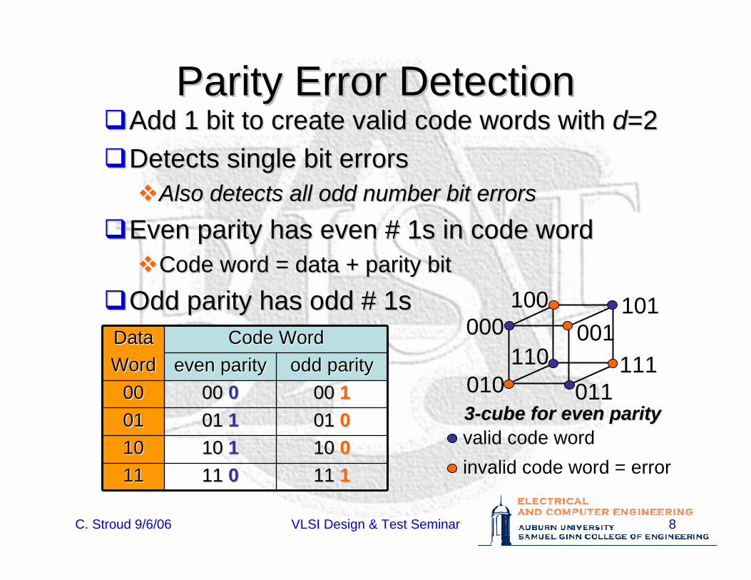
Parity Error DetectionParity Error DetectionAdd 1 bit to create valid code words with Add 1 bit to create valid code words with dd=2=2Detects single bit errorsDetects single bit errors
Also detects all odd number bit errorsAlso detects all odd number bit errors
Even parity has even # 1s in code wordEven parity has even # 1s in code wordCode word = data + parity bitCode word = data + parity bit
Odd parity has odd # 1sOdd parity has odd # 1s
33--cube for even paritycube for even parity
000 001
010 011
100 101
110 111
valid code wordinvalid code word = error
Code WordCode WordDataDataWordWord
11 11 1111 11 00111110 10 0010 10 1110100101 0001 01 11010100 00 1100 00 000000
odd parityodd parityeven parityeven parity
C. Stroud 9/6/06 VLSI Design & Test Seminar 9
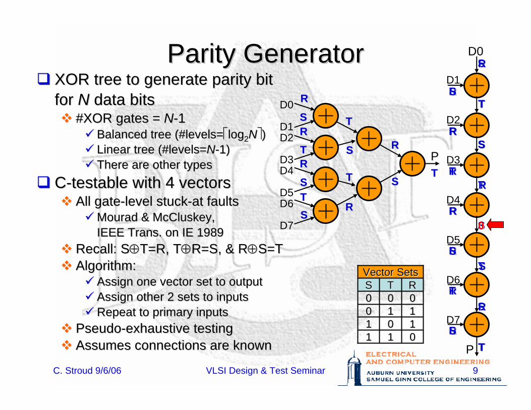
Parity GeneratorParity GeneratorXOR tree to generate parity bit XOR tree to generate parity bit for for NN data bitsdata bits
#XOR gates = #XOR gates = NN--11Balanced tree (#levels=Balanced tree (#levels=⎡⎡loglog22NN⎤⎤))Linear tree (#levels=Linear tree (#levels=NN--1)1)There are other typesThere are other types
CC--testable with 4 vectorstestable with 4 vectorsAll gateAll gate--level stucklevel stuck--at faultsat faults
MouradMourad & & McCluskeyMcCluskey,,IEEE Trans. on IE 1989IEEE Trans. on IE 1989
Recall: SRecall: S⊕⊕T=R, TT=R, T⊕⊕R=S, & RR=S, & R⊕⊕S=TS=TAlgorithm:Algorithm:
Assign one vector set to outputAssign one vector set to outputAssign other 2 sets to inputsAssign other 2 sets to inputsRepeat to primary inputsRepeat to primary inputs
PseudoPseudo--exhaustive testingexhaustive testingAssumes connections are knownAssumes connections are known
D0
D1D2
D3D4
D5D6
D7
P
D1
D2
D3
D4
D5
D6
D7
P
D0
Vector SetsVector Sets
00111100RR
1111001111000000TTSS
TTSS
RR
TT
SS
TT
RR
SSRR
RR
TT
SSTTSS
RR
TT
SS
SS
TT
SS
TT
TT
SS
RR
RR
RR
RR
RR
RR
RR
TT
RR
00
TT
SS
SS
RR
RR
SS
RR
TT
SS
TT
SS
RR
C. Stroud 9/6/06 VLSI Design & Test Seminar 10
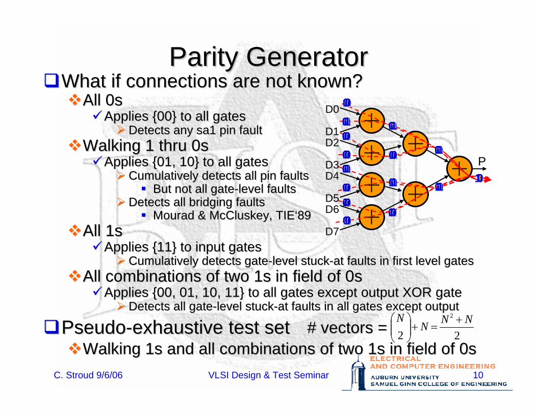
Parity GeneratorParity GeneratorWhat if connections are not known?What if connections are not known?
All 0sAll 0sApplies {00} to all gatesApplies {00} to all gates
Detects any sa1 pin faultDetects any sa1 pin faultWalking 1 thru 0sWalking 1 thru 0s
Applies {01, 10} to all gatesApplies {01, 10} to all gatesCumulatively detects all pin faultsCumulatively detects all pin faults
But not all gateBut not all gate--level faultslevel faultsDetects all bridging faultsDetects all bridging faults
MouradMourad & & McCluskeyMcCluskey, TIE, TIE‘‘8989All 1sAll 1s
Applies {11} to input gatesApplies {11} to input gatesCumulatively detects gateCumulatively detects gate--level stucklevel stuck--at faults in first level gatesat faults in first level gates
All combinations of two 1s in field of 0sAll combinations of two 1s in field of 0sApplies {00, 01, 10, 11} to all gates except output XOR gateApplies {00, 01, 10, 11} to all gates except output XOR gate
Detects all gateDetects all gate--level stucklevel stuck--at faults in all gates except outputat faults in all gates except output
PseudoPseudo--exhaustive test setexhaustive test setWalking 1s and all combinations of two 1s in field of 0sWalking 1s and all combinations of two 1s in field of 0s
D0
D1D2
D3D4
D5D6
D7
P00
00
00
00
00
00
00
0000
00
00
000000
0011
00
11
11
00
00
00
0011
00
00
000000
0011
00
11
11
00
00
00
1100
00
00
000000
0011
00
11
00
11
00
00
0000
00
11
000000
0011
00
11
00
11
00
00
0000
11
00
000000
0011
11
00
00
00
11
00
0000
00
00
110000
0011
11
00
00
00
11
00
0000
00
00
000000
1111
11
00
00
00
00
11
0000
00
00
000011
0011
11
00
00
00
00
11
0000
00
00
001100
00
22
2 NNNN +
=+⎟⎟⎠
⎞⎜⎜⎝
⎛# vectors =# vectors =
0000
00
00
00
00
00
1111
11
11
111111
1100
00
00
00
00
00
00
1111
00
00
000000
0000
00
00
11
11
00
00
0011
11
00
000000
0000
00
00
11
11
00
00
0011
00
11
000000
0000
11
11
11
00
11
00
0011
00
00
000000
1100
11
11
11
00
11
00
0011
00
00
110000
0000
11
11
11
00
00
11
0011
00
00
001100
0000
11
11
11
00
00
11
0011
00
00
000011
0000
00
00
11
11
00
00
1100
11
00
000000
0000
00
00
11
11
00
00
1100
00
11
000000
0000
11
11
11
00
11
00
1100
00
00
000000
11
C. Stroud 9/6/06 VLSI Design & Test Seminar 11
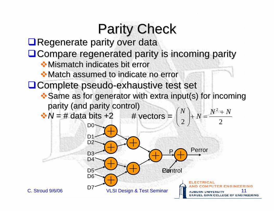
Parity CheckParity CheckRegenerate parity over dataRegenerate parity over dataCompare regenerated parity is incoming parityCompare regenerated parity is incoming parity
Mismatch indicates bit errorMismatch indicates bit errorMatch assumed to indicate no errorMatch assumed to indicate no error
Complete pseudoComplete pseudo--exhaustive test setexhaustive test setSame as for generator with extra Same as for generator with extra input(sinput(s) for incoming ) for incoming parity (and parity control)parity (and parity control)NN = # data bits +2= # data bits +2
Perror
Pin
D0
D1D2
D3D4
D5D6
D7
P
Control
22
2 NNNN +
=+⎟⎟⎠
⎞⎜⎜⎝
⎛# vectors =# vectors =
C. Stroud 9/6/06 VLSI Design & Test Seminar 12
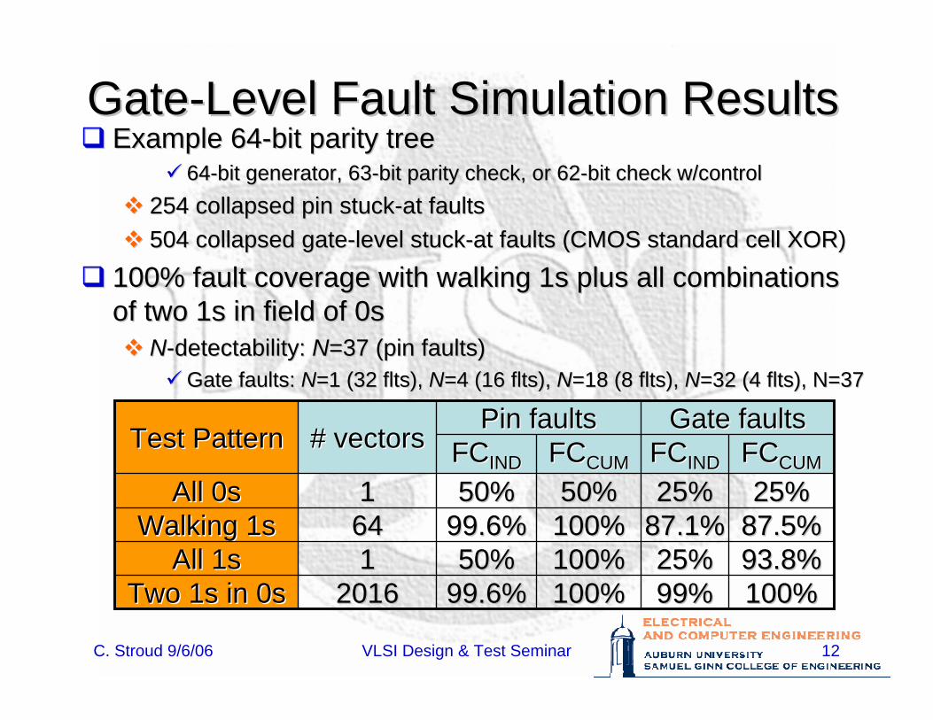
GateGate--Level Fault Simulation ResultsLevel Fault Simulation ResultsExample 64Example 64--bit parity treebit parity tree
6464--bit generator, 63bit generator, 63--bit parity check, or 62bit parity check, or 62--bit check w/controlbit check w/control254 collapsed pin stuck254 collapsed pin stuck--at faultsat faults504 collapsed gate504 collapsed gate--level stucklevel stuck--at faults (CMOS standard cell XOR)at faults (CMOS standard cell XOR)
100% fault coverage with walking 1s plus all combinations 100% fault coverage with walking 1s plus all combinations of two 1s in field of 0sof two 1s in field of 0s
NN--detectabilitydetectability: : NN=37 (pin faults)=37 (pin faults)Gate faults:Gate faults: NN=1 (32 =1 (32 fltsflts), ), NN=4 (16 =4 (16 fltsflts), ), NN=18 (8 =18 (8 fltsflts), ), NN=32 (4 =32 (4 fltsflts), N=37), N=37
100%100%99%99%100%100%99.6%99.6%20162016Two 1s in 0sTwo 1s in 0s93.8%93.8%25%25%100%100%50%50%11All 1sAll 1s87.5%87.5%87.1%87.1%100%100%99.6%99.6%6464Walking 1sWalking 1s25%25%25%25%50%50%50%50%11All 0sAll 0s
FCFCCUMCUMFCFCINDINDFCFCCUMCUMFCFCINDIND
Gate faultsGate faultsPin faultsPin faults# vectors# vectorsTest PatternTest Pattern
C. Stroud 9/6/06 VLSI Design & Test Seminar 13
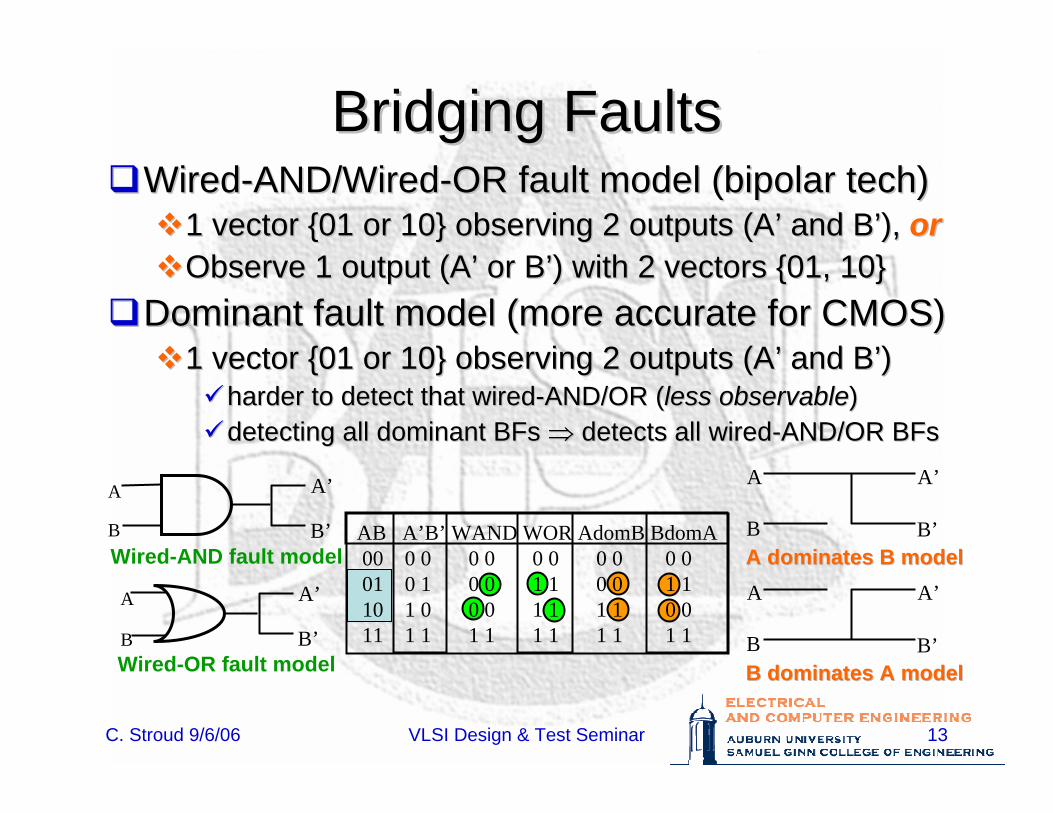
Bridging FaultsBridging FaultsWiredWired--AND/WiredAND/Wired--OR fault model (bipolar tech)OR fault model (bipolar tech)
1 vector {01 or 10} observing 2 outputs (A1 vector {01 or 10} observing 2 outputs (A’’ and Band B’’), ), ororObserve 1 output (AObserve 1 output (A’’ or Bor B’’) with 2 vectors {01, 10}) with 2 vectors {01, 10}
Dominant fault model (more accurate for CMOS)Dominant fault model (more accurate for CMOS)1 vector {01 or 10} observing 2 outputs (A1 vector {01 or 10} observing 2 outputs (A’’ and Band B’’))
harder to detect that wiredharder to detect that wired--AND/OR (AND/OR (less observableless observable))detecting all dominant BFs detecting all dominant BFs ⇒⇒ detects all wireddetects all wired--AND/OR BFsAND/OR BFs
A
B
A’
B’A dominates B modelA dominates B modelA
B
A’
B’B dominates A modelB dominates A model
A
B
A’
B’Wired-AND fault model
A
B
A’
B’Wired-OR fault model
AB A’B’ WAND WOR AdomB BdomA00 0 0 0 0 0 0 0 0 0 0 01 0 1 0 0 1 1 0 0 1 110 1 0 0 0 1 1 1 1 0 011 1 1 1 1 1 1 1 1 1 1
C. Stroud 9/6/06 VLSI Design & Test Seminar 14
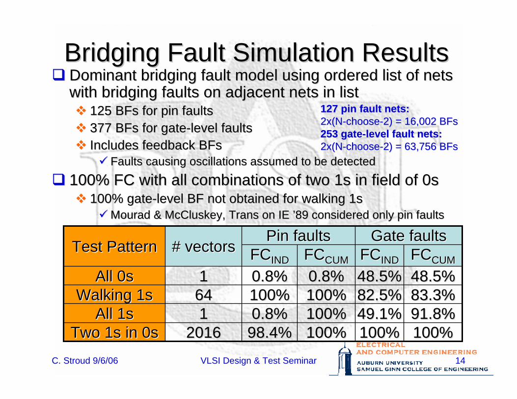
Bridging Fault Simulation ResultsBridging Fault Simulation ResultsDominant bridging fault model using ordered list of nets Dominant bridging fault model using ordered list of nets with bridging faults on adjacent nets in listwith bridging faults on adjacent nets in list
125 125 BFsBFs for pin faultsfor pin faults377 377 BFsBFs for gatefor gate--level faultslevel faultsIncludes feedback Includes feedback BFsBFs
Faults causing oscillations assumed to be detectedFaults causing oscillations assumed to be detected
100% FC with all combinations of two 1s in field of 0s100% FC with all combinations of two 1s in field of 0s100% gate100% gate--level BF not obtained for walking 1slevel BF not obtained for walking 1s
MouradMourad & & McCluskeyMcCluskey, Trans on IE , Trans on IE ’’89 considered only pin faults89 considered only pin faults
100%100%100%100%100%100%98.4%98.4%20162016Two 1s in 0sTwo 1s in 0s91.8%91.8%49.1%49.1%100%100%0.8%0.8%11All 1sAll 1s83.3%83.3%82.5%82.5%100%100%100%100%6464Walking 1sWalking 1s48.5%48.5%48.5%48.5%0.8%0.8%0.8%0.8%11All 0sAll 0sFCFCCUMCUMFCFCINDINDFCFCCUMCUMFCFCINDIND
Gate faultsGate faultsPin faultsPin faults# vectors# vectorsTest PatternTest Pattern
127 pin fault nets:127 pin fault nets:2x(N2x(N--choosechoose--2) 2) = 16,002 = 16,002 BFsBFs253 gate253 gate--level fault nets:level fault nets:2x(N2x(N--choosechoose--2) 2) = 63,756 = 63,756 BFsBFs
C. Stroud 9/6/06 VLSI Design & Test Seminar 15
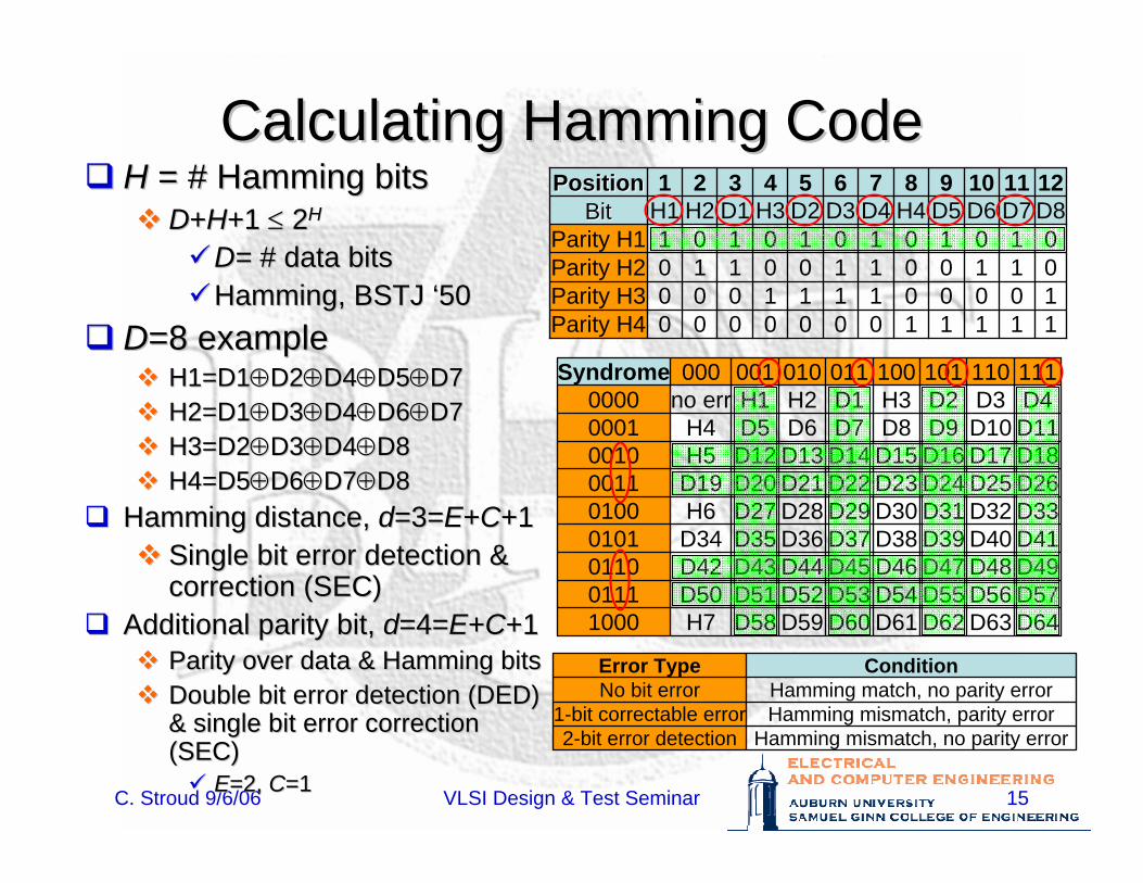
Calculating Hamming CodeCalculating Hamming CodeHH = # Hamming bits= # Hamming bits
DD++HH+1 +1 ≤≤ 22HH
D= D= # data bits# data bitsHamming, BSTJ Hamming, BSTJ ‘‘5050
DD=8 example=8 exampleH1=D1H1=D1⊕⊕D2D2⊕⊕D4D4⊕⊕D5D5⊕⊕D7D7H2=D1H2=D1⊕⊕D3D3⊕⊕D4D4⊕⊕D6D6⊕⊕D7D7H3=D2H3=D2⊕⊕D3D3⊕⊕D4D4⊕⊕D8D8H4=D5H4=D5⊕⊕D6D6⊕⊕D7D7⊕⊕D8D8
Hamming distance, Hamming distance, dd=3==3=EE++CC+1+1Single bit error detection & Single bit error detection & correction (SEC)correction (SEC)
Additional parity bit, Additional parity bit, dd=4==4=EE++CC+1+1Parity over data & Hamming bitsParity over data & Hamming bitsDouble bit error detection (DED) Double bit error detection (DED) & single bit error correction & single bit error correction (SEC)(SEC)
EE=2, =2, CC=1=1
121110987654321PositionPosition
1000
H4
0100
H3
0010
H2
0001
H1
11110000Parity H410001110Parity H301101101Parity H201011011Parity H1
D8D7D6D5D4D3D2D1BitBit
D64D63D62D61D60D59D58H71000D57D56D55D54D53D52D51D500111D49D48D47D46D45D44D43D420110D41D40D39D38D37D36D35D340101D33D32D31D30D29D28D27H60100D26D25D24D23D22D21D20D190011D18D17D16D15D14D13D12H50010D11D10D9D8D7D6D5H40001D4D3D2H3D1H2H1no err0000111110101100011010001000Syndrome
Hamming mismatch, no parity error2-bit error detectionHamming mismatch, parity error1-bit correctable errorHamming match, no parity errorNo bit error
ConditionError Type
C. Stroud 9/6/06 VLSI Design & Test Seminar 16
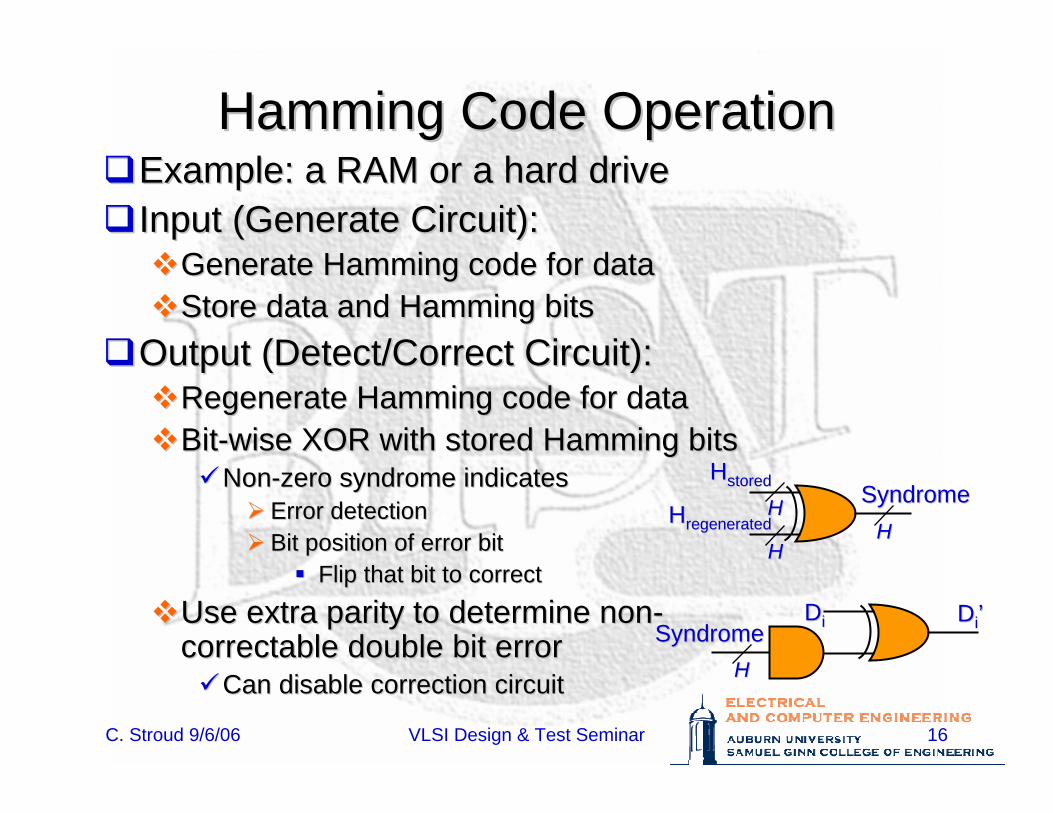
Hamming Code OperationHamming Code OperationExample: a RAM or a hard driveExample: a RAM or a hard driveInput (Generate Circuit):Input (Generate Circuit):
Generate Hamming code for dataGenerate Hamming code for dataStore data and Hamming bitsStore data and Hamming bits
Output (Detect/Correct Circuit):Output (Detect/Correct Circuit):Regenerate Hamming code for dataRegenerate Hamming code for dataBitBit--wise XOR with stored Hamming bitswise XOR with stored Hamming bits
NonNon--zero syndrome indicateszero syndrome indicatesError detectionError detectionBit position of error bitBit position of error bit
Flip that bit to correctFlip that bit to correct
Use extra parity to determine nonUse extra parity to determine non--correctable double bit errorcorrectable double bit error
Can disable correction circuitCan disable correction circuit
HHstoredstored
HHregeneratedregeneratedSyndromeSyndrome
HHHH
HH
DDii DDii’’SyndromeSyndromeHH
C. Stroud 9/6/06 VLSI Design & Test Seminar 17
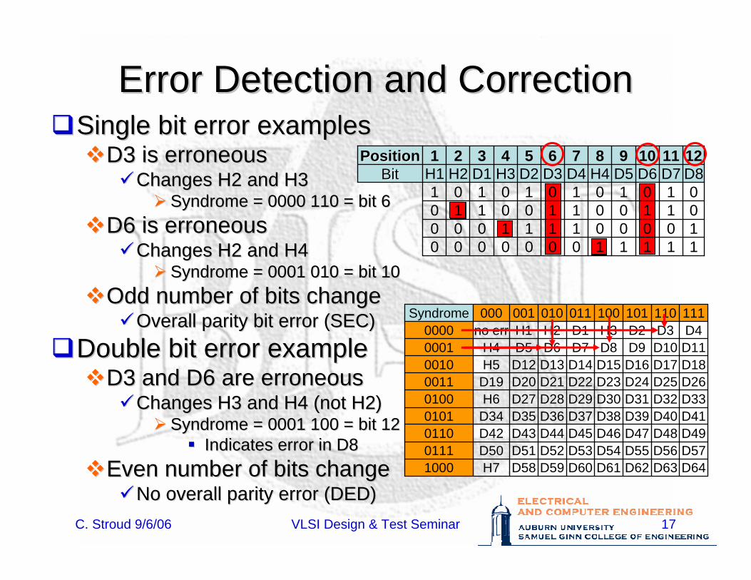
Error Detection and CorrectionError Detection and Correction
D64D63D62D61D60D59D58H71000D57D56D55D54D53D52D51D500111D49D48D47D46D45D44D43D420110D41D40D39D38D37D36D35D340101D33D32D31D30D29D28D27H60100D26D25D24D23D22D21D20D190011D18D17D16D15D14D13D12H50010D11D10D9D8D7D6D5H40001D4D3D2H3D1H2H1no err0000111110101100011010001000Syndrome
Single bit error examplesSingle bit error examplesD3 is erroneousD3 is erroneous
Changes H2 and H3Changes H2 and H3Syndrome = 0000 110 = bit 6Syndrome = 0000 110 = bit 6
D6 is erroneousD6 is erroneousChanges H2 and H4Changes H2 and H4
Syndrome = 0001 010 = bit 10Syndrome = 0001 010 = bit 10Odd number of bits changeOdd number of bits change
Overall parity bit error (SEC)Overall parity bit error (SEC)Double bit error exampleDouble bit error example
D3 and D6 are erroneousD3 and D6 are erroneousChanges H3 and H4 (not H2)Changes H3 and H4 (not H2)
Syndrome = 0001 100 = bit 12Syndrome = 0001 100 = bit 12Indicates error in D8Indicates error in D8
Even number of bits changeEven number of bits changeNo overall parity error (DED)No overall parity error (DED)
121110987654321PositionPosition
1000
H4
0100
H3
0010
H2
0001
H1
11110000100011100110110101011011
D8D7D6D5D4D3D2D1BitBit
C. Stroud 9/6/06 VLSI Design & Test Seminar 18
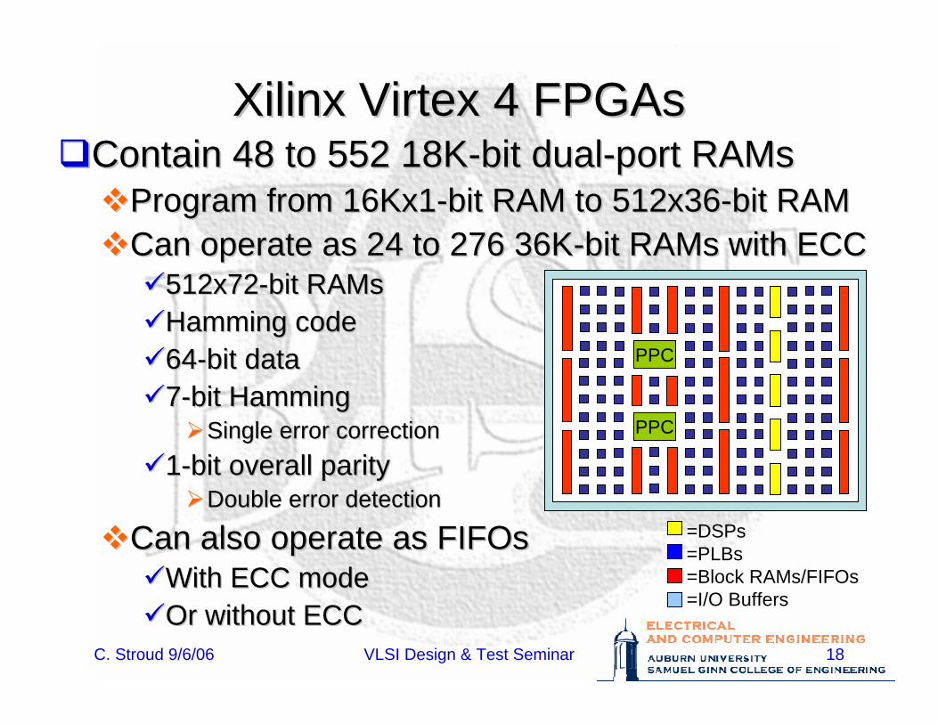
Xilinx Xilinx VirtexVirtex 4 FPGAs4 FPGAsContain 48 to 552 18KContain 48 to 552 18K--bit dualbit dual--port port RAMsRAMs
Program from 16Kx1Program from 16Kx1--bit RAM to 512x36bit RAM to 512x36--bit RAMbit RAMCan operate as 24 to 276 36KCan operate as 24 to 276 36K--bit bit RAMsRAMs with ECCwith ECC
512x72512x72--bit bit RAMsRAMsHamming codeHamming code6464--bit databit data77--bit Hammingbit Hamming
Single error correctionSingle error correction11--bit overall paritybit overall parity
Double error detectionDouble error detection
Can also operate as Can also operate as FIFOsFIFOsWith ECC modeWith ECC modeOr without ECCOr without ECC
=DSPs=PLBs=Block RAMs/FIFOs=I/O Buffers
PPC
PPC
C. Stroud 9/6/06 VLSI Design & Test Seminar 19
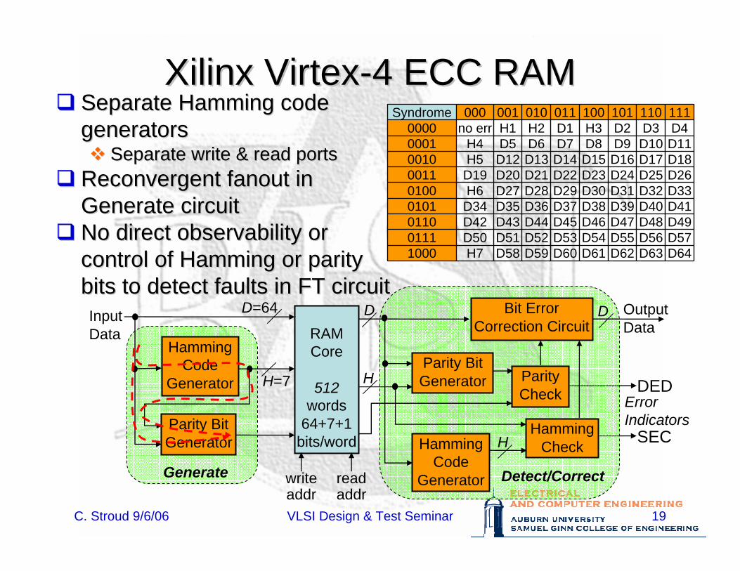
Xilinx VirtexXilinx Virtex--4 ECC RAM4 ECC RAM
D64D63D62D61D60D59D58H71000D57D56D55D54D53D52D51D500111D49D48D47D46D45D44D43D420110D41D40D39D38D37D36D35D340101D33D32D31D30D29D28D27H60100D26D25D24D23D22D21D20D190011D18D17D16D15D14D13D12H50010D11D10D9D8D7D6D5H40001D4D3D2H3D1H2H1no err0000111110101100011010001000SyndromeSeparate Hamming code Separate Hamming code
generatorsgeneratorsSeparate write & read portsSeparate write & read ports
ReconvergentReconvergent fanoutfanout in in Generate circuitGenerate circuitNo direct No direct observabilityobservability or or control of Hamming or parity control of Hamming or parity bits to detect faults in FT circuitbits to detect faults in FT circuit
RAMCore
512words
64+7+1 bits/word
D=64
H=7
InputData
Parity BitGenerator
D
H
HammingCode
Generator
ParityCheck
HammingCheckH
Bit ErrorCorrection Circuit
OutputData
Generate Detect/Correct
HammingCode
Generator
Parity BitGenerator
D
ErrorIndicators
DED
SEC
readaddr
writeaddr
C. Stroud 9/6/06 VLSI Design & Test Seminar 20
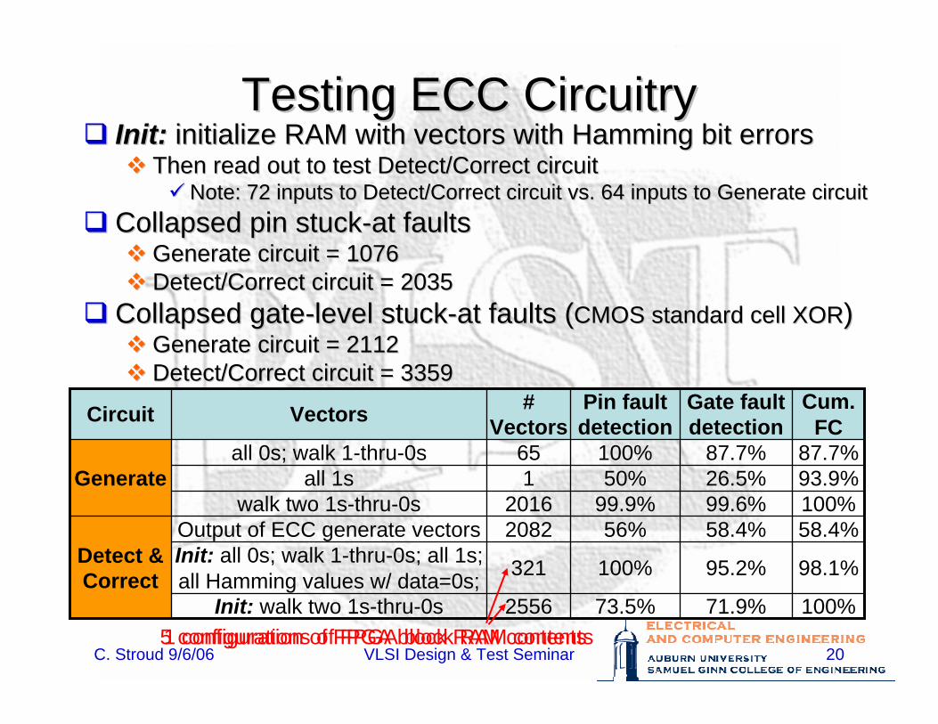
Testing ECC CircuitryTesting ECC CircuitryInit:Init: initialize RAM with vectors with Hamming bit errorsinitialize RAM with vectors with Hamming bit errors
Then read out to test Detect/Correct circuitThen read out to test Detect/Correct circuitNote: 72 inputs to Detect/Correct circuit vs. 64 inputs to GenerNote: 72 inputs to Detect/Correct circuit vs. 64 inputs to Generate circuitate circuit
Collapsed pin stuckCollapsed pin stuck--at faultsat faultsGenerate circuit = 1076Generate circuit = 1076Detect/Correct circuit = 2035 Detect/Correct circuit = 2035
Collapsed gateCollapsed gate--level stucklevel stuck--at faults (at faults (CMOS standard cell XORCMOS standard cell XOR))Generate circuit = 2112Generate circuit = 2112Detect/Correct circuit = 3359Detect/Correct circuit = 3359
100%71.9%73.5%2556Init: walk two 1s-thru-0s
98.1%95.2%100%321Init: all 0s; walk 1-thru-0s; all 1s; all Hamming values w/ data=0s;
58.4%58.4%56%2082Output of ECC generate vectorsDetect & Correct
100%99.6%99.9%2016walk two 1s-thru-0s 93.9%26.5%50%1all 1s87.7%87.7%100%65all 0s; walk 1-thru-0s
Generate
Cum.FC
Gate fault detection
Pin fault detection
# VectorsVectorsCircuit
1 configuration of FPGA block RAM contents5 configurations of FPGA block RAM contents
C. Stroud 9/6/06 VLSI Design & Test Seminar 21
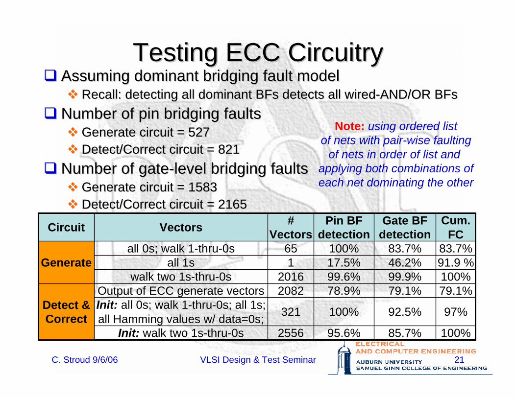
Testing ECC CircuitryTesting ECC CircuitryAssuming dominant bridging fault modelAssuming dominant bridging fault model
Recall: detecting all dominant Recall: detecting all dominant BFsBFs detects all wireddetects all wired--AND/OR AND/OR BFsBFsNumber of pin bridging faultsNumber of pin bridging faults
Generate circuit = 527Generate circuit = 527Detect/Correct circuit = 821Detect/Correct circuit = 821
Number of gateNumber of gate--level bridging faultslevel bridging faultsGenerate circuit = 1583Generate circuit = 1583Detect/Correct circuit = 2165Detect/Correct circuit = 2165
100%85.7%95.6%2556Init: walk two 1s-thru-0s
97%92.5%100%321Init: all 0s; walk 1-thru-0s; all 1s; all Hamming values w/ data=0s;
79.1%79.1%78.9%2082Output of ECC generate vectorsDetect & Correct
100%99.9%99.6%2016walk two 1s-thru-0s 91.9 %46.2%17.5%1all 1s83.7%83.7%100%65all 0s; walk 1-thru-0s
Generate
Cum.FC
Gate BF detection
Pin BF detection
# VectorsVectorsCircuit
Note: using ordered listof nets with pair-wise faulting
of nets in order of list and applying both combinations ofeach net dominating the other
C. Stroud 9/6/06 VLSI Design & Test Seminar 22
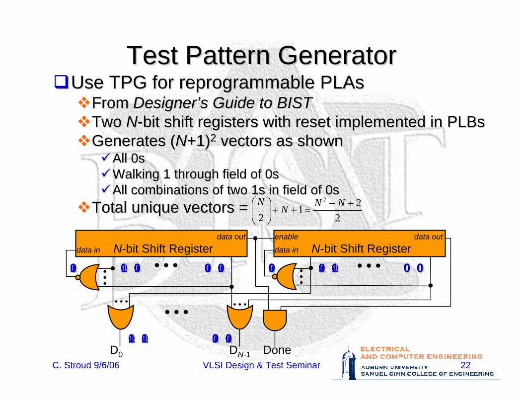
Test Pattern GeneratorTest Pattern GeneratorUse TPG for reprogrammable Use TPG for reprogrammable PLAsPLAs
From From DesignerDesigner’’s Guide to BISTs Guide to BISTTwo Two NN--bit shift registers with reset implemented in bit shift registers with reset implemented in PLBsPLBsGenerates (Generates (NN+1)+1)22 vectors as shownvectors as shown
All 0sAll 0sWalking 1 through field of 0sWalking 1 through field of 0sAll combinations of two 1s in field of 0sAll combinations of two 1s in field of 0s
Total unique vectors =Total unique vectors =2
212
2 ++=++⎟⎟
⎠
⎞⎜⎜⎝
⎛ NNNN
data out
data in N-bit Shift Registerenable data out
data in N-bit Shift Register
D0 DN-1 Done
0 00 0 0 00 0 0 00 0 0 00 011 11
0 00 0 0 00 0
1 01 0 0 00 0 1 01 0 0 00 000 00
1 01 0 0 00 0
0 10 1 0 00 0 1 01 0 0 00 000 00
1 11 1 0 00 0
0 00 0 1 01 0 1 01 0 0 00 000 00
1 01 0 1 01 0
0 00 0 0 10 1 1 01 0 0 00 000 00
1 01 0 0 10 1
0 00 0 0 00 0 0 10 1 0 00 011 00
0 10 1 0 00 0
1 01 0 0 00 0 0 10 1 0 00 000 00
1 11 1 0 00 0
C. Stroud 9/6/06 VLSI Design & Test Seminar 23
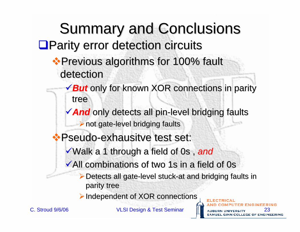
Summary and ConclusionsSummary and ConclusionsParity error detection circuitsParity error detection circuits
Previous algorithms for 100% fault Previous algorithms for 100% fault detectiondetection
ButBut only for known XOR connections in parity only for known XOR connections in parity treetreeAndAnd only detects all pinonly detects all pin--level bridging faultslevel bridging faults
not gatenot gate--level bridging faultslevel bridging faults
PseudoPseudo--exhausitveexhausitve test set:test set:Walk a 1 through a field of 0s , Walk a 1 through a field of 0s , andandAll combinations of two 1s in a field of 0sAll combinations of two 1s in a field of 0s
Detects all gateDetects all gate--level stucklevel stuck--at and bridging faults in at and bridging faults in parity tree parity tree Independent of XOR connectionsIndependent of XOR connections
C. Stroud 9/6/06 VLSI Design & Test Seminar 24
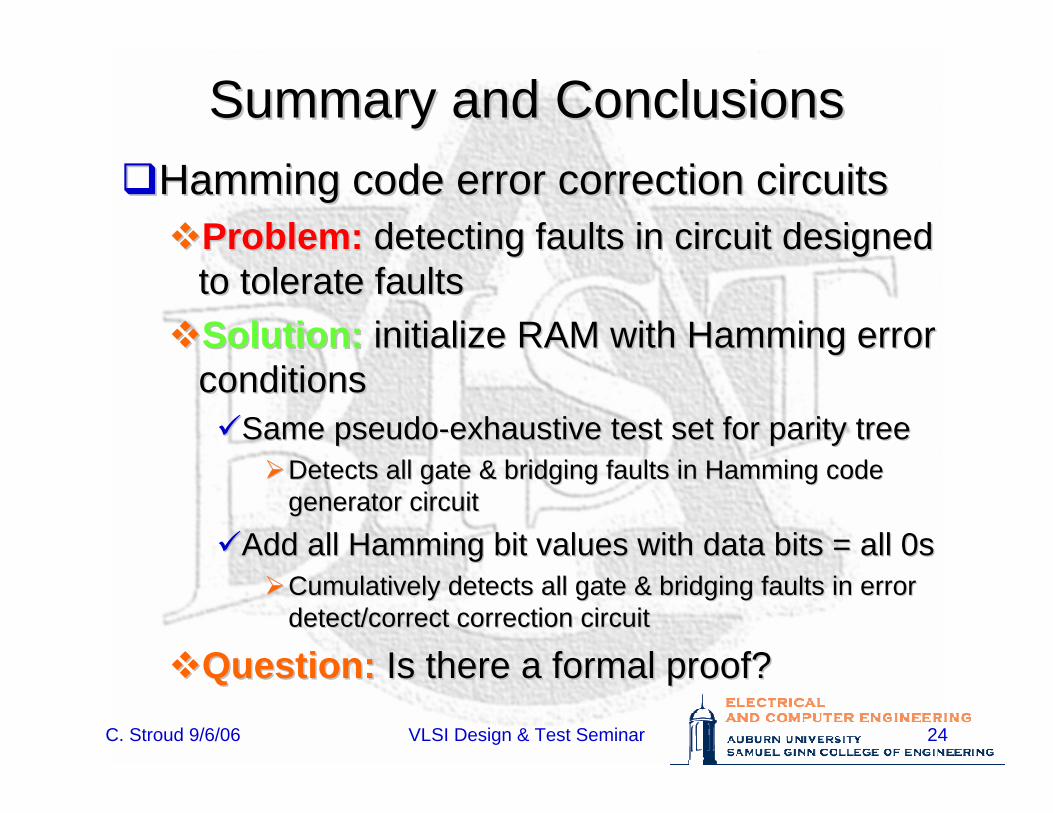
Summary and ConclusionsSummary and ConclusionsHamming code error correction circuitsHamming code error correction circuits
Problem:Problem: detecting faults in circuit designed detecting faults in circuit designed to tolerate faultsto tolerate faultsSolution:Solution: initialize RAM with Hamming error initialize RAM with Hamming error conditionsconditions
Same pseudoSame pseudo--exhaustive test set for parity treeexhaustive test set for parity treeDetects all gate & bridging faults in Hamming code Detects all gate & bridging faults in Hamming code generator circuitgenerator circuit
Add all Hamming bit values with data bits = all 0sAdd all Hamming bit values with data bits = all 0sCumulatively detects all gate & bridging faults in error Cumulatively detects all gate & bridging faults in error detect/correct correction circuitdetect/correct correction circuit
Question:Question: Is there a formal proof?Is there a formal proof?


