NASA Technical Memorandum 107399 AIAA-97-0303 /_/-o2___ 0/03_ Tests of the Performance of Coatings for Low Ice Adhesion David N. Anderson Lewis Research Center Cleveland, Ohio and Allen D. Reich BFGoodrich R&D Center Brecksville, Ohio Prepared for the 35th Aerospace Sciences Meeting & Exhibit sponsored by the American Institute of Aeronautics and Astronautics Reno, Nevada, January 6-10, 1997 National Aeronautics and Space Administration https://ntrs.nasa.gov/search.jsp?R=19970009491 2019-03-12T08:29:49+00:00Z
Transcript
NASA Technical Memorandum 107399
AIAA-97-0303
/_/-o2___
0/03_
Tests of the Performance of Coatingsfor Low Ice Adhesion
David N. Anderson
Lewis Research Center
Cleveland, Ohio
and
Allen D. Reich
BFGoodrich R&D Center
Brecksville, Ohio
Prepared for the
35th Aerospace Sciences Meeting & Exhibit
sponsored by the American Institute of Aeronautics and Astronautics
Tests of the Performance of Coatings for Low Ice AdhesionDavid N. Anderson
NASA Lewis Research Center
Cleveland, Ohioand
Allen D. Reich
BFGoodrich R&D CenterBrecksville, Ohio
Abstract
This paper reports studies of the performance of low-ice-adhesion coatings by NASA Lewis and BFGoodrich.Studies used impact ice accreted both in the NASA LewisIcing Research Tunnel 0R'r) and in the BF_ch IcingWind Tunnel 0WI') and static ice in a BFGoodrich bench-
top parallel-plate shear rig. Early tests at NASA Lewisinvolved simple qualitative evaluations of the ease ofremoving impact ice from a surface. Coated surfaces werecompared with uncoated ones. Some of the coatings weretested again with static ice at BFGoodrich to obtainquantitative measurements. Later, methods to mtablish theadhesion force on surfaces subjected to impact ice wereexplored at Lewis. This paper descffoes the various testprograms and the results of testing some of the coatingsevaluated over the past 5 years. None of the coatings werefound to be truly ice-phobic; however, the most effectivecoatings were found to reduce the adhesion of ice to about½ that of an uncoated aluminum surface.
This paper descn_:s tests performed to compare theadhesion of ice on uncoated aluminum with that on
surfaces with various coatings. Most of the tests describedhere have been performed on impact ice in icing tunnels atNASA Lewis Research Center and at BF_ch
Aerospace. Because static ice has different stmctme andproperties from impact ice, tests were also made with staticice using a BFGoodrich bench-top shear rig to comparewith the impact-ice results.
NASA Lewis has performed icing research for over 50years, operating the world's largest refrigerated icingtunnel, the Icing Research Tunnel 0RT). During that time
numerous requests have been received fi_omorganizations
ranging in size from individual inventors to largecorporations to test "ice-phobic" coatings that the sponsorbelieved would prevent ice from adhering to aircraftsurfaces_ Such requests have been accomodated whenevertunnel schedule permitted, because the development of low-adhesion coatings has always been viewed as having thepotential to improve the performance of ice-protectionsystems.
BFGoodfi'ch Aerospace manufactures pneumatic-boot ice-protection systems, the oldest and most widely-used systemfor protecting aircraft component leading edge surfacesfrom in-flight ice accretion. The boot works by periodicallyinflating to break the bond of accreted ice with the surfaceand lifting the ice so that the airflow over the surface cancarry the shattered ice pieces away. If the adhesion of theice to the surface of the boot could be reduced, the energy
required to break the ice-surface bond could be reduced aswell. There are two primary benefits of reducing iceadhesion: ice protection systems requiring lower energycould be used and the removal of ice would be cleaner.
Because of the potential benefits in ice-protection systemperformance, BFGoodrich maintains an interest inthedevelopment of low ice-adhesion coatings,13
Early studies of static-ice adhesion to surfaces wereperformed by Loughborough and Haas _ and byLoughborough 2. They evaluated the different parameterswhich affected ice adhesion and found that the adhesion
strengthincreasedlinearly with decreasing temperature. Inthese studies, silicones reduced the adhesion of ice, but asmall layer of silicone was stripped away with each iceremoval, so this was not a permanent coating.Loughborough and Haas 1noted that a poor correlationexists between low ice adhesion and water repellancy.
Results from simple evaluations of coated surfacesperformed by NASA Lewis before the studies given herehave not been published. However, anecdotal reports fi_mthesetestshave indicated that while ice adhesion togreased
surfacesappearedtobe nearly zero,aerodynamic forcesheld the ice in place and permitted it to accrete normally 4.
Scavuzzo and Chus and Scavuzzo, Chu and Kellackey 6
have made extensive studies of ice accretion along with
other properties of impact ice. They found no effect of
accretiontemperatureovertherangeOf-22°C (-8°F) toabout -4°C (25°F) with a linear decrease in _hesive shearstress fiom -5°C (23°F) to 0°C (32°F). They a/so reportedthat adhesive shear stress increases slightly with increasingairspeed and increasing droplet size.
Recently, Reich 3reported static ice adhesion to silicone
coatings on a neoprene substrate; measurements were madeusing a paraUel-plate shear test apparatus. He performedmultiple ice removals to establish the stability of thecoating with respect to repeated deicing. Reductions inshear strength up to a factor of 10 compared with un_neoprene were demoustratecL For some coatings, the shearstrength increased with repeated ice removals, while forothers, it decreased. Explanations were proposed for themechanisms for these behaviors. Silicone grease was foundto exlu'oit icephobic characteristics initially, but shearstrength increased rapidly with repeated ice removals. Rainerosion was shown to increase ice adhesion significantly,even for short exposure times. Thus, while very lowadhesion is poss_le, durability must be demonstrated bothfor repeated ice removals and for rain impingement atalrc_ speeds.
Test Facilities
NASA Lewis Icing Research Tunn_l The NASA Lewis
Icing _ Tunnel (IRT) has been described inreference 7. The IRT has a test section width of 2.7m(9fl) and a height of 1.8 m (6 t_) With a model blocking 5%of the test-section cress-sectional area, airspeeds up to 160m/s (350 mph) can be achieved. A refrigeration systemprovides control of the test-section temperature from -30 io
I°C (-20 to 33°F) within 4-.5oc (± loID. The water-spraysystem has 8 spray bars and is used with either of two setsof spray nozzles, known as the NASA standard and mod-Inozzles. The droplet median volume diameter has beencah_oratedover the range ofl5 to 40 tun and thetest-section liquid-water content, from .2 to 3.4 g/m 3. Forthe tests reported here, the rood-1 nozzles were used.
BFGoodrich Icing Wind T0nnel The BF_ch IcingWind Tunnel (IWT) has a test section width of 56 cm (22in) and a height of l12cm(44in). Test-sectionairspeedscan be varied from 13 m/s (30 mph) to 103 m/s (230 mph).Test-section temperatures can be controlled to within _-.5°C (± I°F) in the range o£-30 to 0°C (-22 to 32°F). Thewater-spray system uses 7 spray bars. The use of eitherNASA standard or mod-I nozzles gives test-section dropletmedian volume diameters controllable fzom 5 to 50 pmwith liquid-water contents in the range of .1 to 3 g/m 3.
Summary of Test Techniques and Results
Through the years, several approaches have been used toevaluate low-adhesion coatings. Table 1 is a smnma_ ofthe experimental methods used by NASA Le_s and thematings tested in the past 5 years. In addition to thesetests, studies of particular coatings have been performed byBFGooddch as part of a joint effort to identify coatingseffeoive for ice-protection sy_ms. The studies and theirresults will be described here.
Oualitative T_t$ in the IRT Early tests of coatings in theIRT tended to be somewhat casual, with few or nomeasurements of performance and no published reports ofthe results. The simplest tests in the IRT involved insertinga specimen coated with a believed "ice phobic" into thetunnel to determine if ice would accrete. These tests can
often be performed at the same time as another test in the
tunnel test se_ion. Test coatings have included a variety ofmaterials, including greases, several forms of teflon anddiamond-like coatings (DLC). These tests showed that iceaccretes even on a "zero"-adhesion surface such as grease,and for many inventors who believed they had developed anice-phobic, the demonstration of ice accreting on theircoating has been ve_ educational.Thesetestsshowed thatwhile the adhesion of ice may be reduced significantlycompared with an uncoated surface, the aerodynamicforces present in flight will hold an ice formation in place.It became apparent that zero ice adhesion was not apractical goal for in-flight ice protection, but that reducedadhesion mightbehelpful in improving the performance ofice-protection systems.
Com Daritlve Tests With 7.6-cm Cylinders in IRT Latertests recorded ice shapes as well as subjective impressionsof the effort required to remove ice from coated anduncoated surfaces. Tests were made using 7.6-cm- O-in-)diameter hollow aluminum cylinders mounted vertically inthe tunnel test section as shown in Figure l(a). Severalcylinders were prepared with different coatings, butcylinders were tested individually. Each cylinder had three7.6-cm- (3-in-) wide bands which could he coated; thecoated bands were separated by 5-cm (2-in) widths ofuncoated aluminum. The test cylinder was mounted suchthat the middle of the center band was at the tunnelcentefline. It is at the tunnel centerline that the cloud
¢_xWorationapplies; positions away from the centerline mayexperience slightly different liquid-water contents.
2
Ice was accreted on thes_ cylinders at static temperatures of-1, -4 and -18°C (30, 25 and 0°F), test-section velocities of45 and 112 m/s (100 and 250 mph), water droplet median-volume diameters of 15, 25 and 40 ttm and liquid-watercontents of .5, I and 1.8 g/m 3. Spray times were adjusteddepending on test conditions to maintain a constant iceaccumulation; times varied from 5 to 25 minutes. At the
!l
completion of the spray, a heated aluminum plate was usedto melt a 6.4-ram (l/4-in) gap through the ice at each of thecoated portionsof the cylinder as well as at an uncoatedstrip. Ice shapeswere tben recorded by inserting acardboard template into each gap and tracing the outline ofthe ice. Finally, the ice growth on each coated band wasisolated by melting additional thin gaps in the ice at the topand bottom of each band; a subjective assessment of theease with which the ice could be removed was obtained by
striking a light blow to the ice with a teflon rod.
Among the coatings tested were a hydrophobic treatmentfor aircraft windshields (PPG Surface Sealm), a DowChemical "Anti-Stick" developmental water-basedfluorocarbon (refs. 8,9), a second Dow coating and FreecomCeram-Kote M TM, a commercial ceramic-epoxy coating
used in petroleum, marine and sewage applications toprotect against corrosion and erosio_ Each of these wasapplied to the center 7.6-cm-wide band of one cylinder witha Teflon-filled paint (Deft Aliphatic Polyurethane Coatingwith Teflon, MIL-C-83286B) applied to the top band andBFGoodrich Icex applied to the bottom band. Icex is asilicone-based product marketed as a coating forelastomeric deicing boots to reduce ice adhesion. It was notexpected to perform well on aluminum. Ice accreted on theuncoated aluminum between the coated bands was alsoobserved, the shape was recorded, and the ease of removalwas noted as a reference for the coated-surface results.
Among these coatings, only the Dow "Anti-Stick" appearedto reduce the adhesion of ice compared with the uncoatedsurface. The Ceram-Kote 54 TM appeared to increase theadhesion. The Surface Seal TM, Icex and Teflon paints all
performed about the same as the uncoated aluminum.Although the Teflon provides a very slippery surface withhigh water repellency, it also has a high pore density whichprobably encourages strong mechanical bonding with theice.
Figure 10a) shows the cylinder with ice accret_ For thistest, the center band was coated with Dow "Anti-Stick." Asfor all the tests, the top band had the Teflon paint and thebottom, Icex. There was no evident effect of the coating oneither the quantity of ice accreted or its appearance.
This observation was confirmed by comparing tracings ofthe ice shape formed on the coated bands and the uncoated
part of the cylinder. Two examples of such tracings areshown in Figure 2. Figure 2(a) gives ice shapes resultingfrom tests with a droplet median volume diameter (MVD)of 15 ttm, and Figure 2(b) gives shapes for anMVD of 40tun. At each of the two test conditions, the surface coatinghad no effect on the final ice shape. The small differencesbetween the ice shapes in each figure were typical of thevariations produced by the IRT cloud nonuniformity.These results were consistent with those of Hansman and
Turnock_°who also found that ice shapes were independentof the material on which accretion occurred_
Studies using high-magnification images (references 11and 12) have shown that water coalesces into beads during
glaze-ice a_retio_ Because of this, if the beading processis altered, one could expect the final ice shape to change.The lack of a surface effect in this study can be understood
by considering that once a thin layer of ice has formed overthe model, water impinging and freezing will see only theice surface; any substrate effects are totally masked) 2
Although these cylinder tests provided a standardized testfixtnre they gave only a subjective evaluation of thedifficulty of removing ice from the cylinder. Some of thesesame coatings were also tested with the BFGoodrichparallel-plate shear apparatus to establish quantitativeresults.
BFGo0drich Parallel-Plate Shear Tests This test apparatushas been discussed in reference 3. Figure 3 is a sketchwhich illustrates the test method. Static ice was frozen in a
thin layer (about 1.8 mm (.07 in)) between a movablepedestal and a stationary platform. Both surfaces werecooled by circulating a refrigerated alcohol solutionthrough the pedestal support and the platform. Freezingtook 1 - 2 minutes, but the ice was allowed to stabilize for 3
minutes before applying force. A gear motor drove thelinear stage on which the pedestal was mounted, and theforce was measured with a load cell. The adhesion strengthof the ice to the surface was found by dividing the force
required to shear the ice, F, by the surface area, A, withsmall corrections for the stress concentration.
The coatings tested on the 7.6-era-diameter cylinder in theIRT, the "Anti-Stick," Surface Seal TM and Ceram-Kote54 TM, were also tested in the BFGoodrich shear test stand.
Figure 4 gives the adhesive strength of static ice on thethree coatings and on the uncoated aluminum substrate.Results are given for 20 repeated ice removals. A linearregression fit has been made for each set of data. It is
evi'dent that the Dow coating displayed fairly repeatableadhesive strength which increased tittle with number of iceremovals. However, these data are not sufficient to provethe long-term durability of the coating. The Surfa_ Seal TM
gave highly variant results from test to test and appeared toshow increasing adhesive force with time. An explanationfor this type of variability has been proposed by Reich3. Itshould be noted that Surface Seal has shown excellent
durability and effectiveness as a hydrophobic coating foraircraft windshields, but was not developed as a coating for
aluminun_ Ice adhered more strongly to the Ceram-Kote54TM thantotheuncoatedaluminum surface.
Impact ice, such as that resulting from the IRTexperiments, has different physical characteristics from the
static ice of the BFGoodrich shear-fig tests. Nevertheless,the quantitative shear results were fury consistent with thequalita_e IRT observations. This consistency tends toconfirm the validity of the static-ice shear-test method as a
simple but meaningfid screening technique. Oncepromising coatings have been identified with static ice,follow-up tests in an icing tunnel can be made toresults with impact ice.
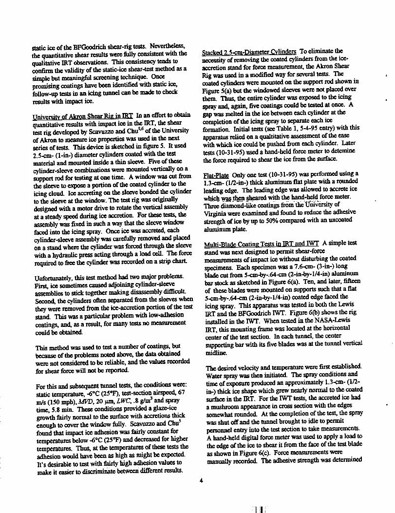
UnivcrsiW of Akron Shear Rig in IRT In an effort to obtainquantitative results with impact ice in the IRT, the sheartest rig developed by Scavuzzo and Chus'6of the Universityof Akron to measure ice properties was used in the nextseries of tests. This device is sketched in figure 5. It used2.5-¢m- (1-in-) diameter cylinders coated with the testmaterial and mounted inside a thin sleeve. Five of these
cylinder-sleeve combinations were mounted vertically on asupport rod for testing at one time. A window was cut fromthe sleeve to expose a portion of the coated cylinder to theicing cloud. Ice accreting on the sleeve bonded the cylinderto the sleeve atthe window. The test rig was originallydesigned with a motor drive to rotate the vertical assemblyat a steady speed during ice accretion. For these tests, theassembly was fixed in such a way that the sleeve windowfaced into the icing spray. Once ice was accreted, eachcylinder-sleeve assembly was carefully removed and placedon a stand where the cylinder was forced through the sleevewith a hydraulic press acting through a load cell. The forcerequired to free the cylinder was recorded on a strip chart.
Unfortunately, this test method had two major problems.First, ice sometimes caused adjoining cylinder-sleeveassembfies to stick together making disassembly dif_cult.Second, the cylinders often separated from the sleeves whenthey were removed from the ice-accretion portion ofthe teststand. This was a particular problem with low-adh_ion
coatings, and, as a result, for many tests no measurementcould be obtained.
This method was used to test a number of coatings, butbecause of the problems noted above, the data obtainedwere not considered to be reliable, and the values recordedfor shear force will not be reporte_
For this and subsequent tunnel tests, the conditions were:static temperature, -6°C (25°F), test-section airspeed, 67m/s (150 mph), MVD, 20 _ LWC, .8 g/m 3 and spraytime, 5.8 rain. These conditions provided a glaze-icegrowth fairly normal to the surface with accretions thickenough to cover the window fully. Scavuzzo and Chu s
found that impact ice adhesion was f_irly constant fortemperatures below -6°C (25°F) and decreased for highertemperatures. Thus, at the temperaUtres of these tests theadhesion would have been as high as might be expected.It's desirable to test with fairly high adhesion values tomake it easier to discriminate between different results.
_tacked 2.5-cm-Diameter Cylinders To eliminate thenecessity of removing the coated cylinders f_om the ice-accretion stand for force measurement, the Akron ShearRig was used in a modified way for _ t_'tS. _coated cylinders were mounted on the support rod shown inFigure 5(a) but the windowed sleeves were not placed overthem. Thus, the entire cylinder was exposed to the icingspray and, again, five ceatings could be tested at once. Agap was melted in the ice between each cylinder at thecompletion of the icing spray to separate each iceformation. Initial tests (see Table 1, 5-4-95 entw) with thisapparatus relied on a qualtitative assessment of the easewith which ice could be pushed from each cylinder. Latertests (10-31-95) used a hand-held force meter to deteminethe force required to shear the ice from the surface.
Flat-Plate Only one test (10-31-95) was performed using a1.3-cm- (1/2-in-) thick aluminum flat plate with a roundedleading edge. The leading edge was allowed to accrete icewhich _ then _ with the hand-held force meter.Three diamond-like coatings fi'om the'university ofVirginia were examined and found to Mu_ the adh_strength of ice by up to 50% compared with an uncoatedaluminum plate.
Multi-Blade Coating Tests in_IRT and IWT A simple teststand was next designed to permit shear-forcemeasurements of impact ice without disturbing the coatedspecimens. Each specimen was a 7.6-cm- (3-in-) longblade cut from 5-cm-by-.64-cm (2-in-by-l/4-in) aluminumbar stock as sketched in Figure 6(a). Ten, and later, fifteenof these blades were mounted on supports such that a flat5-cm-by-.64-cm (2-in-by-l/4-in) coated edge faced theicing spray. This apparatus was tested in both the LewisIRT and the BFGoodrich IWT. Figure 6(b) shows the riginstalled in the IWT. When tested in the NASA-Lewis
IRT, this mounting frame was located at the horizontalcenter of the test section. In each tunnel, the centersupporting bar with its five blades was at the tunnel verticalmidliue.
The desired velocity and temperature were first established.Water spray was then initiatecL The spray conditions andtime of exposure produced an approximately 1.3-cm- (1/2-in-) thick iceshapewhichgrewnearlynormalto the coatedsurface inthe IRT. For the IWTtests, the accreted ice had
a mushroom appearance in cross section with the edgessomewhat rounded. At the completion of the test, the spraywas shut off and the tunnel brought to idle to permitpersonnel ent_ into the test section to take measurements.
A hand-held digital force meter was used to apply a load tothe edge of the ice to shear it f_om the face of the test bladeas shown in Figure 6(c). Force measurements were
manually recorded. The adhesive strength was determined
i] ! i
by dividing the recorded force by the face area, 3.2 cm 2 (.5in2) and applying a correction for stress concentration.
An analysis of stress concentration was not made for thepresent study, howler, a reasonable value to use may beestimated from published sources. Scavuzzo and Chus
I_rformed a finite-element analysis on their shear-testgeometny and found that an average stress concentration ofapproximately 2 could be _pfiM Rmch _pli_ ananalytical solution for his parallel-plate shear rig3 andplotted the ratio of the measured to the true adhesivestrength as a function of the ratio of the ice thickness to thesample length. In the present tests, the ice thickness wasabout 1 cm (%in), and the length of sample was 5 cm (2in). For a ratio of thickness to length of.2 - .25, the stressconcentration from Reich's plot is about 1.3. Because ofthe manner in which force is applied in the multi.bladetests, the stress concentration can be expected to be higherthan that found from Reich's plot; thus, the value of 2 fromScavuzzo and Chu was thought to be more probable, andeven this may be conservative. Thus, all multi-blade damreported here have had a factor-of-2 stress concentrationappliecL
Figure 7 compares the adhesive strength of impact-ice withthat of static ice. Both types of ice were accreted onuncoated alumimml surfaces. The impact-ice data are fromIWT tests using the multi-blade stand shown in Figure 6(b).An uncoated blade was mounted in the center of each of the
horizontal support bars. The three sets of data representthe blade at the top, at the middle and at the bottom supportbar. Adhesion values from the top and bottom bars wereabout the same, while the center bar produced adhesivestrengths about 20% higher than the other two. A possibleexplanation for this difference is the proximity of the topand bottom bars to the ceiling and floor of the tunnel. It ispos,_ole that temperatures at these positions were higherthan at the conter, and, if so, the resulting adhesivestrel_gthwould be reduced relative to the center bar.Temperature measurements in the IWT were not taken toso it is not known if temperature gradients exist in thattunnel.
Figure 8 shows the results of a series Of IRT tests with themulti&lade rig using experimental polymers produced byElastic Ceramic Coatin"gs. In each test, an uncoated bladewas mounted in _ _nter of each bar as a reference, andthe adhesive strength from the uncoated blade is reportedfor comparison with the coaled results. The coatings forwhich the ice adhesion sAre_ngth is shown in Figure 8 wereapplied to blades mounted on the same support bar, thus,the adhesion _ngths for the uncoated reference are thesame for both coatings. Results for coating 7B are given inFigure 8(a) and for coating 8B, Figure 8(b). For thesecoatings, the adhesive strength of ice was initially abouthalf that of the uncoated aluminum with a few individual
results even lower. The adhesive strength increased as icewas repeatedly removed until the sixth removal whenadhesion approached that of the uncoated blade. Clearly,these coatings do not have adequate durability at this time.The coated samples displayed less variation from test to testthan the uncoated.
Figure 9 shows adhesion strengths for a fluoropolymer-based Du Pont coating, one of a number of coatings testedwith the multi-blade rig in the IWT. The same coating wasapplied to two blades to determine possible effects ofvariability of the application procedure. The two bladeswere initially mounted on the top support bar. After 9 iceremovals, the first blade was moved to the middle support,and testing with the second blade was terminated. For thefirst 9 removals, both coated-blade results are comparedwith the uncoated-aluminum reference blade on the topsupport bar. For removals 10 - 17, the uncoated referencewas on the center bar.
Figure 9(a) shows ice adhesion strength for 17 ice-removaltests with the first blade; and Figure 9(b), adhesion strength
for the 9 _m_oy0s_ on the _n d blade. _ applicationsgave adhesion strengths about half that from the uncoatedrc_crcnce. There did not _ to be any drama_c changein the adhesive strength when the first blade was movedfrom the top to the middle bar. For 17 ice removals, thelinear regression fit through the data was nearly fiat; thisresult suggests the possibility of good durability.
The dotted line in Figure 7 gives the average adhesivestrength found in reference 3 for static ice on uncoatedaluminum. The value was close to the initial impact-iceresults from the center bar of the multi-blade test. It was
shown above that the qualitative rankings for variouscoatings was the same from the static-ice shear rig and the7.6-cm cylinder impact ice tests. The comparison in Figure7 now also shows fairly good quantitative agreement
between static-ice and impact-ice tests, although there issome uncertainty in the correct stress concentration for thelatter results.
Consistency between the tests performed in the BFGoodfichIWT and the NASA Lewis IRT can be seen in the
uneoated-blade data in Fig_es 8 and 9. In both tunnels,the average impact-ice adhesive strengths for uncoatedaluminum were in the range of 7- 9 xlOs nt/m 2 (100 - 130
psi).
Concluding Remarks
This paperreviewed'_eral years' testing of 10w-ice-adhesion coatings. Test methods started with simplequalitative _ in the NASA Lewis Icing Research Tunnel
0RT) comparing the relative ease of impact ice removal
fromcoated and uncoated surfaces. Coatings which
appeared to have potential for significant reductions in iceadhesion were also tested with static ice in a BFGoodrich
shear rig. Methods to obtain shear-force measurementswith impact ice in the IRT and the BFGoodrich IWT were
described with results for some of the coatings.
R was apparent f_om _se tests that the amount and shapeof the ice accreted in the wind tunnel were dependent solelyon tunnel and cloud conditions, not on the surface on which
the ice accretecL Although the shape of the ice a_ret_xi is
dependent on surface effects such as water beading and
nmback, soon after the start of exposure to the icing cloud,
the coated surface becomes covered with a layer of ice;
subsequent accretion occurs on a surface of ice, whoseintera_on with water is the same regardless of the original
subsume characteristics.
Results from tests with hydrophobic coatings is of interest
because this class of materials has at times been proposat
as having icephobic characteristics. One of the
hydrophobics tested was intended for use on glass, notaluminum, and it gave no reduction in shear adhesion on
aluminum. Results for this type of material were
inconclusive, but it would appear that hydrophobicity does
not necessarily produce icephebicity.
Of particular note, the test results showed consistency
between impact-ice tests in icing tunnels and a static-ice
shear test. It appears to be posm_ole to reach validconclusions about the shear sUcngths of impact ice on
coated surfaces by performing static-ice tests. Additional
tests to validate the static-ice approach should be
undertaken, however. The static-ice test is simpler and
considerably less expensive to perform than a tunnel test; it
makes sense, then, to conduct future screening programs
with a static-ice shear test. After ranking coatings in this
way, those coatings showing particular promise should alsobe tested in a tunnel with impact ice.
5. Scavuzzo, ILL. and Chu, M.L., "Structural Properties of
Impact Ices Accreted on Aircraft S_," NASA
Contractor Report, CR-179580, January, 1987.
6. Scavuzzo, ILL., Chu, M.L. and Kellackey, C.J.,
"S_uctt_ Analysis and Properties of Impact Ices Accretedon Aircraft Structures," NASA ConUactor Report, CR-
19s4_3, Ap_ 1996.
7. Soeder, Ronald I-L, Sheldon, David W., Andracchio,
Charles, R., Ide, Robert F., Spera, David A. and Lalli, Nick
M., "NASA Lewis Icing Research Tunnel User Manual,"
NASA TM 107159, June 1996.
8. Schmidt, Donald L., McCrackin, Perry J. and Ceburn,
Charles E., "Fluorocarbon Containing, Reactive Polymeric
Surfactants and Coating Compesitions Therefrom," Patent
Figure 2. Ice Shapes Observed for Various Surface Treatments. Static Temperature, -10°C (14°F),Velocity, 112 m/s (250 mph); LWC, .5 g/m3; Spray Time, 10 rain.
12 '' ' ' I . I . ' I ' ' ' "'_I' '' '.-A
I0 . •
1 9 Stationary Plate _ 9 - . a
I I _ I Debonded _ '-_
_ =
6:- • • ,
O
5 -* o o -
"_ 4 _ oo °°°°°"" o _"0 0 0 0 O_
_ 3 _ Linear Regressi_ Fit
o Dow Chemical"Anti-Stick" ..32• PPG Surface Seal
1 A Frceeom Ceram-Kote 54
i';"i"Uneo_:] Referene_0 I I I I [ L [ I I [ 1 1 / I I I l
0 5 10 15 20
Figure 3. BFGoodrieh Parallel-Plate Shear Rig.Dimensions in era.
Number of Removals, n
Figure 4. Adhesion Strength of Static Ice on 3 Coatings.Tests Using BFGoodrich Parallel-Plate Shear Rig.
170
160
150
140
130
120 "_
80 m
70 ._
50 <
40
'30
20
10
0
1.9 Diam---_
2.5Diana ___>{_
7.6-_[.
Window _I !
Support Rod
Coated
Cylinder
Sleeve
CylinderInstalled IntoSleeve
ITunnel Ceiling
Flow terfine
// \\ Tunnel// ___.oor
(a) Detailsof Cylinder and Sleeve Assembly. Co) Assembled Test Stand in IRT.
Figure 5. University of Akron Shear Rig. Dimensions in cm.
10
i!1 !11{
Support0.6 ___ ___-_
Coated I _ '"--.<:.Surface
Flffw "
(a) Close-up View of Blade. Dimensions in cm.
Figure 6. Multi-Blade Coatings Test
_:_ Co) Test Stand Assembly in BFGoodrich IWT.
12
II
10
_ 9
% 8
% 7
ID
•_ 4
3
2
1
0
[]
[] Cl -,li
it m -
" o o ._ _____.-- _D
.=_._ ....°. ........."-'_'=" O ""16......... 6" In" I:Y"" "-'
II [] ._
_ "i_".... A
B o '_- A o II
o
----o---Impact Ice: Bar 1 (Top)
v---Impact Ice: Bar 2 (Middle)_- _ Impact Ice: Bar 3 (Bottom)............... Static lee: Reich 3
I I I , I i i I I I I I i i I I
0 5 lO 15
.
. 6050
40
-- 30-- 20
-- I0
i i 0
20
Number ofRemovals,n
170
160
150
140
130120 "_
110 ",_
80 _
"/0 ._
(c) Digital Force Meter Applied to Ice
Figure 6. (concluded) Figure 7. Comparison of Impact-Ice and Static-Ice Shear Meas-urements on Uncoated Aluminum. Impact IceData From Multi-Blade Test in IWT; Static-IceResults From BFGoodrich Parallel-Plate Shear Rig3.
_: -11o- ............ ' ......................................................... ._ loo
b -!,9°
o o."D'I
I I I 1
2 3 4 5
z
Z 2O
- 10
06
5o4O
30
Number of Removals, n Number of Removals, n
(a)Coating7I]. (b)Coating813.
Figure 8. Elastic Ce_tmic Coatings Results Using Multi-Blade Test Stand in NASA Lewis IRT.
12
11
10
9
8
7
.6
5
4
3
2
1
00
' ' ' I J ' ' ' I _ ' ' , _ , o , ,_-
[]
0 0
0 ..°-''"*
°°°*"
°.....°...°°°°°" rl[] 0 o
° .°.-'''''"° []
D O
O O
--0 oO
• •
ZO0 • • •
Coat_l.
.... O .... Uncoated
J J J _ I J J J J } I J _ _ I J , J
4O
30
20
I0
0lO 15 20
12170
160 11
150140 10
130 9
1208
110
100 7
9O 68O7O 5
6O 45O
3
2
1
00
I I I I I II I i....
[] o
[]
....... _ ......... • ...................... n
[]
D 0 0
• • •• ______m
I I I I I
l 2 3 4 5
Coated
..... o .... Uncoated
I I I I
6 7 $ 9
Number of Removals, n Number of Removals,n
(a) Coating1 Applied to First Blade. (a)CoatingIAppliedtoS_,,ondBlade.
Figure 9. Du Pont Coaling 1 Results Using Multi-Blade Test Stand in BFGoodrich IWT.
12
170
160
150
140
130
120 "_
II0 @
g0
70 ._
so _
40
30
20
10
'010
Form ApprovedREPORT DOCUMENTATION PAGE OMBNo. 0704-0188
Public repoding burden for this collection of information is estimated to average 1 hour per response, including the time for reviewing instructions, searching existing data sources,
gathedng and maintaining the data needed, and completing and reviewing the collection of information. Send commen_ regarding this burden estimate or any olher aspecl of this
collection of information, including suggestions for reducing this burden, to Washington Headquarters Services, Directorate for Information Operations and Reports, 1215 Jefferson
Davis Highway, Suite 1204, Arlington, VA 22202-4302, and to the Office of Management and Budget, Paperwork Reduction Project (0704-0188), Washington, DC 20503.
1. AGENCY USE ONLY (Leave blank) 2. REPORT DATE
January 1997
4. TITLE AND SUBTITLE
Tests of the Performance of Coatings for Low Ice Adhesion
6. AUTHOR(S)
David N. Anderson and Allen D. Reich
7. PERFORMING ORGANIZATION NAME(S) AND ADDRESS(ES)
National Aeronautics and Space Administration
Lewis Research Center
Cleveland, Ohio 44135-3191
9. SPONSORING/MONITORING AGENCY NAME(S) AND ADDRESS(ES)
National Aeronautics and Space Administration
Washington, DC 20546- 0001
3. REPORT TYPE AND DATES COVERED
Technical Memorandum
5. FUNDING NUMBERS
WU-548-20-23
8. PERFORMING ORGANIZATIONREPORT NUMBER
E- 10604
10. SPONSORING/MONITORINGAGENCY REPORT NUMBER
NASA TM- 107399
AIAA-97-0303
11. SUPPLEMENTARY NOTES
Prepared for the 35th Aerospace Sciences Meeting & Exhibit sponsored by the American Institute of Aeronautics and Astronautics,
Reno, Nevada, January 6-10, 1997. David N. Anderson, NASA Lewis Research Center and Al]en D. Reich, BFGoodrich R&D Center,
9921 Brecksville Road, Brecksville, Ohio 44141. Responsible person, David N. Anderson organization code 5840, (216) 433-3585.
12a. DISTRIBUTION/AVAILABILITY STATEMENT
Unclassified - Unlimited
Subject Category 02
This publication is available from the NASA Center for AeroSpace Information, (301) 621-0390.
12b. DISTRIBUTION CODE
13. ABSTRACT (Maximum 200 words)
This paper reports studies of the performance of low-ice-adhesion coatings by NASA Lewis and BFGoodrich. Studies
used impact ice accreted both in the NASA Lewis Icing Research Tunnel (IRT) and in the BFGoodrich Icing Wind Tunnel
(IWT) and static ice in a BFGoodrich bench-top parallel-plate shear rig. Early tests at NASA Lewis involved simple
qualitative evaluations of the ease of removing impact ice from a surface. Coated surfaces were compared with uncoated
ones. Some of the coatings were tested again with static ice at BFGoodrich to obtain quantitative measurements. Later,
methods to establish the adhesion force on surfaces subjected to impact ice were explored at Lewis. This paper describes
the various test programs and the results of testing some of the coatings looked at over the past 5 years. None of the
coatings were found to be truly ice-phobic; however, the most effective coatings were found to reduce the adhesion of ice
to about 1/2 that of an uncoated aluminum sample.
14. SUBJECT TERMS
Aircraft safety; Ice protection; Icing; Coatings
17. SECURITY CLASSIFICATIONOF REPORT
Unclassified
NSN 7540-01-280-5500
18. SECURITY CLASSIFICATIONOF THIS PAGE
Unclassified
19. SECURITY CLASSIFICATIONOF ABSTRACT
Unclassified
15. NUMBER OF PAGES14
16. PRICE CODE
A03
20. LIMITATION OF ABSTRACT
Standard Form 298 (Rev. 2-89)Prescribedby ANSI Std.Z39-1829B-102