Step 1: Preparing the GeometryStep 2: Creating a Material PointStep 3: Generating the Octree MeshStep 4: Generating the Delaunay MeshStep 5: Smoothing the MeshStep 6: Saving the Project
Preparation
1. Copy the input geometry file (helicopter.tin) from the ANSYS installation directory underv140/icemcfd/Samples/CFD_Tutorial_Files/Helicopter to the working directory.
2. Start ANSYS ICEM CFD and open the geometry (helicopter.tin).
File > Geometry > Open Geometry...
Step 1: Preparing the Geometry
In most cases, you would put the parts comprising the helicopter fuselage into a single part and thenbuild topology to extract feature curves. In this tutorial, you will retain each surface in its own part tobetter illustrate the patch-independence. Also, you will skip the build topology step and instead extractthe feature curve from the symmetry plane.
1. Enable Surfaces under Geometry in the display control tree.
Geometry Surfaces
2. Zoom in to the helicopter fuselage and examine the geometry.
The overlapping surfaces and slivers are shown in Figure: Overlapped Surfaces and Slivers (p. 108).
Figure: Overlapped Surfaces and Slivers
3. Create an assembly for all the fuselage surfaces.
b. Click (Select surface(s)) and click (Select all appropriate visible objects) in the selectiontoolbar.
You need not click the middle-mouse button when using the Select all appropriate visible objectsoption. You can also type v to select visible objects.
Note
In this example, it may be easier to select the symmetry plane surface using asingle left-button click. For complex models which have more surfaces, it will beeasier to use Select all appropriate visible objects or Select items in a part, oreven the box selection.
c. Click Apply.
Step 2: Creating a Material Point
Geometry > Create Body
1. Enter FLUID for Part.
2. Ensure that Points is enabled in the display control tree.
3. Retain the selection of Centroid of 2 points for Location.
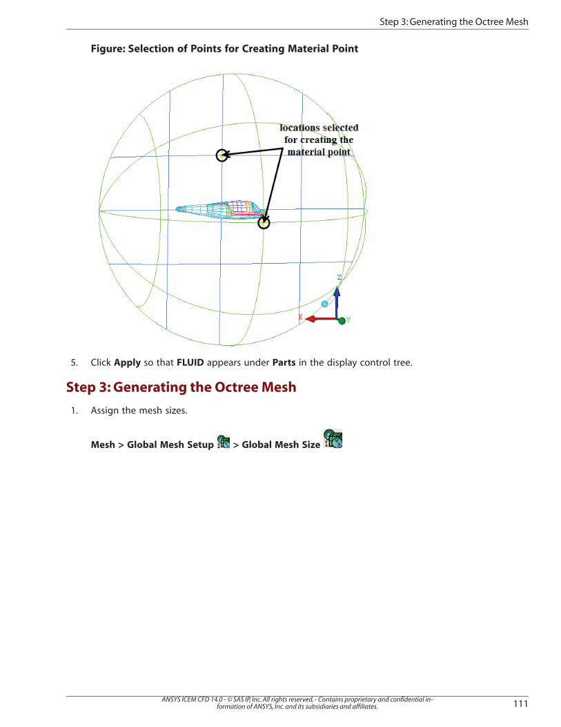
4. Click (Select location(s)) and select two locations such that the midpoint lies within the volume(one on the symmetry surface and other on the far-field surface, see Figure: Selection of Points for Cre-ating Material Point (p. 111)). Click the middle-mouse button to accept the selection of the points.
a. Select (Measure Distance) from the utilities and measure the length of the aircraft.
The length of the aircraft is around 2422.
b. Click (Select geometry) and select the density box in the graphics window.
c. Enter 1211 for X Offset.
The X Offset value is chosen approximately half the length of the aircraft.
d. Click Apply.
The density box is translated half the length of the fuselage (Figure: Density Box Translated to theWake Region (p. 114). You will use this to refine the wake region.
Figure: Octree Mesh for Helicopter (p. 116) shows the Octree mesh. The various colors help illustratethe patch independence. View the wake region and examine the prism layers. The prism height“floats" as the height was initially set to zero. The variation in layer thickness (float) is not signi-ficant for this model because the surface mesh size is relatively uniform. You may try with differentmesh sizes, or with curvature based refinement for greater effect. Figure: Zoomed-in Mesh—SliversMeshed with Equilateral Triangles (p. 116) shows the zoomed in slivers meshed with equilateraltriangles.
Figure: Zoomed-in Mesh—Slivers Meshed with Equilateral Triangles
Note
Some solvers may not like the volume transitions in the Octree mesh. Step 4 ex-plains how you can replace the Octree volume mesh with a Delaunay volumemesh for smoother volume transition.
b. Click Apply to check for errors and possible problems in the mesh.
Make sure no errors/problems are reported during the check.
Step 4: Generating the Delaunay Mesh
In this step, you will replace the Octree mesh with the Delaunay mesh because it fills the volume more effi-ciently and has smoother volume transition.
1. Set the volume mesh parameters.
Mesh > Global Mesh Setup > Volume Meshing Parameters
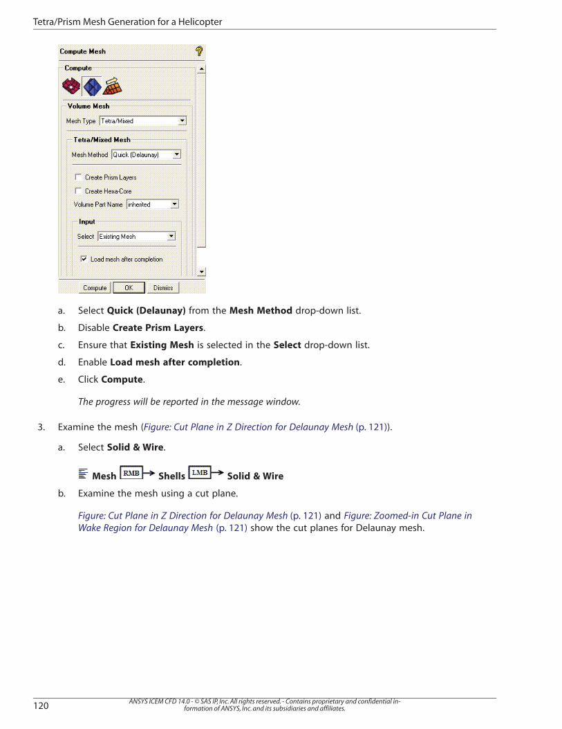
a. Select Quick (Delaunay) from the Mesh Method drop-down list.
a. Select Quick (Delaunay) from the Mesh Method drop-down list.
b. Disable Create Prism Layers.
c. Ensure that Existing Mesh is selected in the Select drop-down list.
d. Enable Load mesh after completion.
e. Click Compute.
The progress will be reported in the message window.
3. Examine the mesh (Figure: Cut Plane in Z Direction for Delaunay Mesh (p. 121)).
a. Select Solid & Wire.
Mesh Shells Solid & Wire
b. Examine the mesh using a cut plane.
Figure: Cut Plane in Z Direction for Delaunay Mesh (p. 121) and Figure: Zoomed-in Cut Plane inWake Region for Delaunay Mesh (p. 121) show the cut planes for Delaunay mesh.
Figure: Cut Plane in Z Direction for Delaunay Mesh
Figure: Zoomed-in Cut Plane in Wake Region for Delaunay Mesh
4. Check the mesh for any errors that may cause problems during the analysis.
Edit Mesh > Check Mesh
Step 5: Smoothing the Mesh
In this step, you will smooth the mesh to improve the quality. The smoothing approach involves initialsmoothing of the interior elements without adjusting the prisms. After initial smoothing, you will smooththe prisms as well.
The quality histogram appears in the right hand corner.
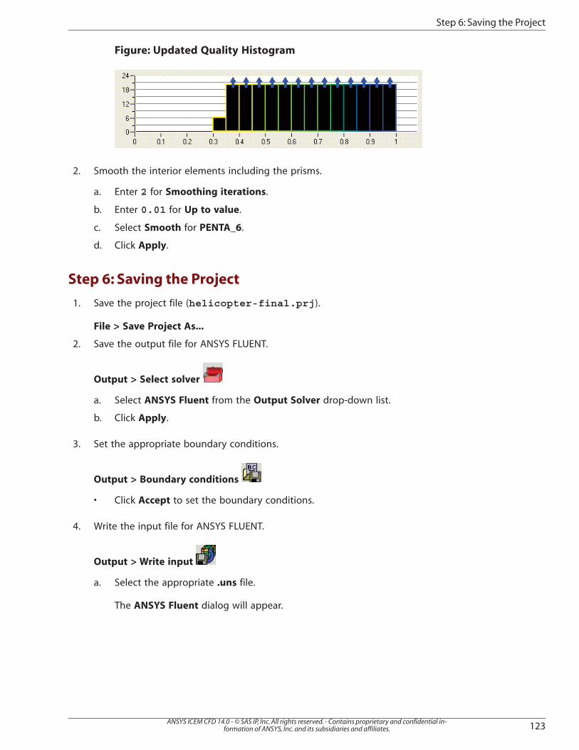
1. Smooth the interior elements without adjusting the prisms.
a. Enter 25 for Smoothing iterations.
b. Enter 0.5 for Up to value.
c. Retain the selection of Quality for Criterion.
d. Select Freeze for PENTA_6.
Note
The PENTA_6 elements are five sided elements with six nodes (such as prismelements). These elements are usually ideal, but may be damaged by thesmoother as it adjusts to optimize the adjacent tetra nodes. Freezing these prismelements (PENTA_6) protects them. If you smooth some prism elements, use asubset or reduce the number of smoothing iterations and the Up to value downto 0.01 so that only the worst elements are adjusted.
e. Click Apply.
The quality histogram will be updated as shown in Figure: Updated Quality Histogram (p. 123).