70
2011/12/20 1 www.ti.com/smartgrid Texas Instruments Smart Grid Business Unit

2011/12/20 1
www.ti.com/smartgrid
Texas Instruments Smart Grid Business Unit

Agenda
- WW Smart Grid Activities
- TI Smart Grid Business Unit
-TI PLC Development & Roadmap
- HW Architecture
- plcSUITE
- TI PLC FlexOFDM
- TI PLC Standard Activities
- TI PLC field test overview
- TI PLC certification and lab test procedure
WW Smart Grid Activities

2011/12/20
4
Overview about WW Smart Grid activities North America
- Obama announced $3.5B USD government stimulus funding for Smart Grid
- US is one of the leading countries in moving to a smart grid
- Main communication technologies used:
a) meter to grid RF mesh <1GHz
b) meter to home area network (HAN) RF 2.4GHz ZigBee
- Smart Grid applications move to all IPv6 which demands higher performance &
high memory application processors
-Smart Energy Profiles at Home Area Network for smart appliances, energy monitor,
etc
- OFDM based Power Line Communications for Grid-2-home, solar panel/solar
farms, smart building, street lighting applications
2011/12/20
5
Overview about WW Smart Grid activities Europe
- The European Technology Platform (ETP) estimates an investment of €390B USD
until 2030
- Italian utility Enel became the first utility in the world to roll out smart meters (40
million customers. By 2006, Enel had spent $3 billion for smart grid infrastructure and was reaping $750
million in annual savings)
-Iberdrola, ERDF, Enel and E.ON are first rolling out smart meters with PLC
- PLC PRIME standard for AMI/AMR deploying >500K units in Iberdrola Grid in
2011
- PLC G3 standard by ERDF deploying >2K units in French Grid in 2011
- 1Mu rural meters, 34Mu city meters of G1 by ERDF 2012-2013
- France, Spain are the most experienced in PLC implementation (FSK, PRIME)
- W-Mbus for In-Home network connectivity
2011/12/20
6
Overview about WW Smart Grid activities China
- China government invests $$$ on all perspectives of smart grid application: smart
metering (AMR/AMI), solar energy/solar farm, Electrical Vehicle
- China State Grid Corporation Company (SGCC) invests >$30B for 170M units smart e-
meter project from 2010
- 200M rural e-meters will be replaced by the standardized e-meter in 2010- 2011
- CEPRI is the technology arm of SGCC and plays an important role in China e-meter
market
- Standard drafts, lead the bidding, certificate the e-meter
- TI formed strategic relationship with CEPRI for SoC for smart grid market
- China Grid Architecture:
- Core Network Data Concentrator: Wireless (GPRS, etc)
- Data Concentrator Acquisition Unit: LV PLC (main) and Low Power RF
- Acquisition Unit eMeter: RS485 (main) and LV PLC
- Key care-about: Robustness, Cost, Power

7
China State Grid E-meter Project AMR System • LPW and PLC are allowed in the
connection between concentrator and
e-meter or acquisition unit, but PLC
is preferred by State grid now
• Acquisition unit is used to connect the
RS485 e-meter to PLC concentrator
• 1 concentrator or acquisition unit can
support 1 to 32 meters
• ISPN/Optical fiber/ GPRS/CDMA/
Ethernet/ 230M special wireless
network/ mid voltage PLC are
allowed in the connection between
concentrator and server center concentrator
Concentrator Concentrator
Acquisition Unit
Acquisition Unit
PLC e-meter PLC e-meter
e-meter e-meter e-meter e-meter
LV-PLC/
LPW
LV-
PLC/LPW
RS485
Any one of below communication ways:
ISPN
Optical fiber
GPRS/CDMA
230M special network
Ethernet
MV-PLC

TI Smart Grid Business Unit

Smart Grid infrastructure
• Concentrators
• Power Monitoring &
Protection
• Renewable Energy
• HV Circuit Breaker
Smart homes and buildings Smart Meters
• Electricity meter
• Gas meter
• Water meter
• In home display
• Thermostats
• Smart Appliances
•Circuit Breaker
• Charging elect.
vehicle
Focus segments for a Smart Grid
2011/12/20 9
OPA, THS, ADC
Amp, LD, PGA
ADC, DAC
Full range
Various
technologies
Measurement
PLC
10
TI Technologies for Smart Grid Solutions
16-bit ARM + 32-bit
real-time
Microcontrollers ARM-Based
MSP430™
Ultra-low
power
Up to 25 MHz
Flash
1KB to 256KB
RTC, ADC,
MPY, USART
Measurement
metrology MCU
ARM 9, OMAPL1x
Industry std.
High Perf GPP
Accelerator
MMU
USB, LCD MMC, EMAC, LINUX/WinCE
Data Concentrators/ Power Analytics
C2000™
Real-time MCU
ADC, Flash
Protocol
stack & modem
Embedded
Flash f. upgrade
Appropriate
peripherals
PLC Modem
Multi- modulation S-FSK/OFDM
PRIME/G3
Low-power RF
Saving power
CC
RF SoC
transceiver
433 to
2500 MHz
Flash for SoC
Appropriate
peripherals
Mesh-RF
ZigBee®,
WM-Bus
TPS, UCC
AC/DC,
DC/DC, LDO
Full range
Ultra low-power
high efficiency
Metering saving
power
Analog
Complementary Analog
ARM 32-bit
Stellaris® M3
Industry std.
low power
< 100 MHz
Flash 256kB
with path to 2MB
Multi-serial port encryption
Analog integration
Smart Grid
application
processor
Smart Grid Business Unit Marketing, BD, System/Application, Software team, Standardization & Government relations support
11
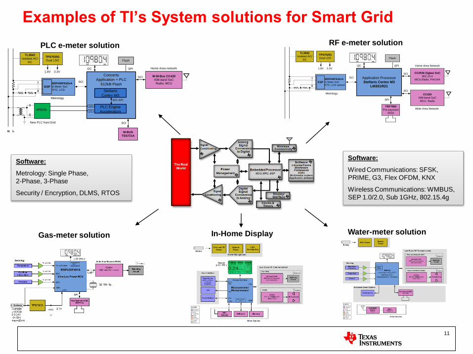
Examples of TI’s System solutions for Smart Grid
Application Processor
Stellaris Cortex M3
LM3S1R21
MSP430FE42xA
E-Meter SoC
RTC, LCD options
I
V
ESP. . .
MAXCUM
A
B
C
D
E kWhREACTEST kW
SCI
CC2530 Zigbee SoC
802.15.4
MCU,Radio, PA/LNA
SCI
Flash
I2C EPI
CC430
ISM-band SoC
MCU, Radio
SCI
TRF7960
Pre-payment
RFID
SPI
1.8V 3.3V
TL3842
Isolated AC/
DC
TPS70251
Dual LDO
Home Area Network
Wide Area Network
Metrology
Concerto
Application + PLC
512kB Flash
MSP430FE42xA
E-Meter SoC
RTC, LCD
I
V
ESP. . .
MAXCUM
A
B
C
D
E kWhREACTEST kW
LN
PWM
ADC
SCI
Flash
I2C SPI
SCI API
1.8V 3.3V
TL3842
Isolated AC/
DC
TPS70251
Dual LDO
Metrology
PLC Engine
Accelerators
Stellaris
Cortex M3
AFE03x
New PLC front End
M-BUS
TSS721A
SCI
W-M-Bus CC430
ISM-band SoC
Radio, MCU
SCI
Home Area network
PLC e-meter solution RF e-meter solution
Gas-meter solution Water-meter solution In-Home Display
Software:
Wired Communications: SFSK,
PRIME, G3, Flex OFDM, KNX
Wireless Communications: WMBUS,
SEP 1.0/2.0, Sub 1GHz, 802.15.4g
Software:
Metrology: Single Phase,
2-Phase, 3-Phase
Security / Encryption, DLMS, RTOS

TI can offer: Smart meter architecture • HW
•MCU
•RF & RFID
•PLC
•Power
•Analog
• SW
•Metrology
•Zigbee
•PLC
•WMBUS
• expertise
•RF
•PLC
•metrology
•ARM
•security
•support
PLC
MC
U
Metrology
Zigbee
<1GHz RF
Power
RFID
WiFi
2011/12/20 12
TI PLC Development & Roadmap
2011/12/20 14
PLC for Smart Meter Application
Market
- Research reports ~250M installed smart meters by 2015 - Europe and North America are leading with Asia growing fast - PLC is the most adopted communication technology in Smart Meters: 60% share
Popular PLC for Smart Meter Standards: -IEC-61334 S-FSK/G1, PRIME, G3, G.9955, P1901.2
15 15
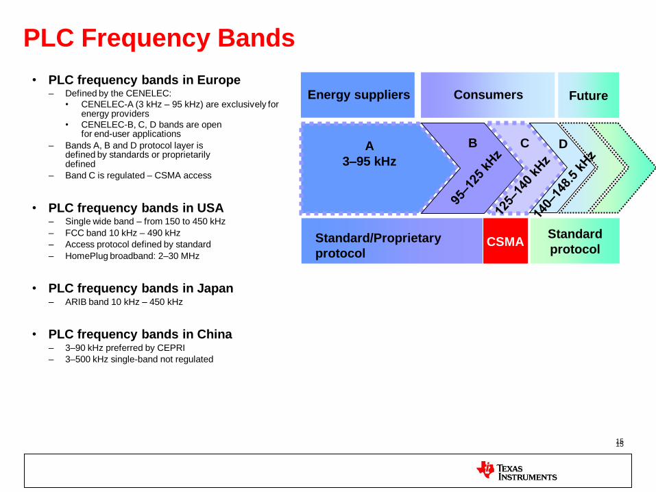
PLC Frequency Bands
• PLC frequency bands in Europe – Defined by the CENELEC:
• CENELEC-A (3 kHz – 95 kHz) are exclusively for energy providers
• CENELEC-B, C, D bands are open for end-user applications
– Bands A, B and D protocol layer is defined by standards or proprietarily defined
– Band C is regulated – CSMA access
• PLC frequency bands in USA – Single wide band – from 150 to 450 kHz
– FCC band 10 kHz – 490 kHz
– Access protocol defined by standard
– HomePlug broadband: 2–30 MHz
• PLC frequency bands in Japan – ARIB band 10 kHz – 450 kHz
• PLC frequency bands in China – 3–90 kHz preferred by CEPRI
– 3–500 kHz single-band not regulated
A
3–95 kHz
B C D
Energy suppliers Consumers Future
Standard/Proprietary
protocol CSMA
Standard
protocol

IEC61334, PRIME, G3 and IEEE P1901.2 Parameter IEC61334 S-FSK PRIME(OFDM) G3(OFDM) P1901.2(OFDM)
Modulation Size
Spread Frequency Shift Keying
DBPSK / DQPSK/D8PSK DBPSK / DQPSK/(D8PSK) DBPSK/DQPSK/D8PSK/
Coherent Modulation
Forward Error Correction
N/A Rate ½ Convolutional
Code Outer RS + inner rate ½
convolutional code Outer RS + inner rate ½
convolutional code
Data Rate
2.4Kbps 21, 42, 64, 84, 64Kbps
(w/ coding) 20.36,/34.76/(46) Kbps
(with coding) Scalable up to 250Kbps
Band plan CENELEC-A Continuous 42-89 KHz
(defined for LV scenario)
36-91 KHz with tone masking for SFSK
CENELEC-A, FCC band
ROBO Mode No No Yes Yes
Tone Mask No No Yes Yes
Adaptive Tone Map
No Yes Yes Yes
MAC IEC61334 MAC PRIME MAC 802.15.4/G3 profile 802.15.4 based
Convergence Layer
IEC61334-4-32 IEC61334-4-32/IPv4 6LoWPAN/IPv6 6LoWPAN/IPv6
Meter Application
COSEM/DLMS COSEM/DLMS, IP COSEM/DLMS, IP COSEM/DLMS, IP
17
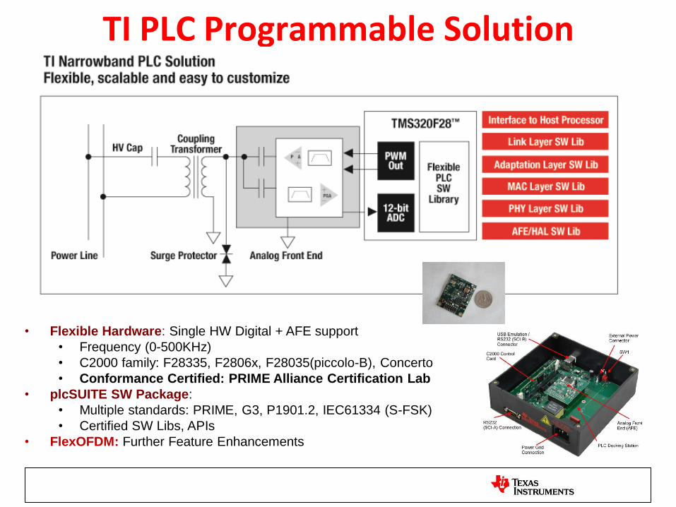
TI PLC Programmable Solution
• Flexible Hardware: Single HW Digital + AFE support
• Frequency (0-500KHz)
• C2000 family: F28335, F2806x, F28035(piccolo-B), Concerto
• Conformance Certified: PRIME Alliance Certification Lab
• plcSUITE SW Package:
• Multiple standards: PRIME, G3, P1901.2, IEC61334 (S-FSK)
• Certified SW Libs, APIs
• FlexOFDM: Further Feature Enhancements

PRIME
Convergence Layer
MAC Layer
PHY Layer
MAC SAP
PHY SAP
Data and Control Plane
MAC
PHY
MLME SAP
PLME SAP
Management Plane
Switch
Terminal
Disconnected Demote Promote
IEC4-32
COSEM AL
COSEM
Interface Model
IPv4/IPv6
TCP/IP
stack
TFTP
FW upgrade
Management
Functions
TI PLC
AppProc
Features
• Terminates @ IEC4-32 LLC in
F28069
• CENELEC-A band
• BPSK, QPSK, 8PSK, ROBO
• IPv4/IPv6*, automatic network
formation
• Resources Usage:
MIPS: ~60MHz Peak
RAM/FLASH: 90KB RAM,
220KB
• Room for eMeter App in F28069
• ROBO tested for crossing LV/MV
transformers
Quality
• Prime Conformance Certified
• Interoperable with 4 major DC
vendors: Current, ZIV, Ormazabal,
Nucleus.
• Mass deployment in Iberdrola grid
G3
TI PLC
AppProc
A
H
F
E
D
cI
G
BJ
PAN coordinator
G3 Mesh Network
Features • Terminates @ 6LoWPAN layer (or
IPv6/UDP)
• CENELEC A, B, C, D, FCC
• Automatic Mesh network
• System Resources
– MIPS: peak ~90 MHz, avg 60MHz
– RAM/Flash: 80KB/220KB
• Both eMeter and mini-concentrator
configure
• DC Support with ARM926
Quality • PHY test vectors IOT with MAXIM
• ERDF G3 Conformance Test Ready
• WW Field Tests: LV/MV transformer crossing, LV/LV field tests

HW Architecture
Application-Specific MCU – What is it?
• ASIP – Application-specific instruction set processor
– Provides special instructions to accelerate PLC computations
• FEC computations (Viterbi acceleration, Galois field arithmetic)
• FFT/IFFT acceleration
• Complex arithmetic
• Security engine (CRC, other instructions to accelerate AES computations)
– Provides instructions to accelerate frequently used computations
• Benefits
– Competes with custom ASIC in terms of cost and power dissipation while
achieving full software programmability
– Reduces MIPS, clock frequency, program memory size
– Lower cost and power than a general purpose DSP / MCU
– Ability to evolve implementations as PLC standards evolve
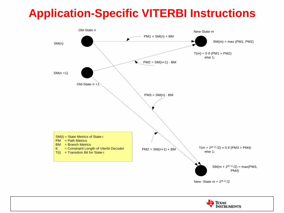
Application-Specific VITERBI Instructions
Old-State n
Old-State n +1
New-State m
New -State m + 2(K-1) /2
SM(n)
SM(n +1)
SM(m) = max (PM1, PM2)
SM(m + 2(K-1) /2) = max(PM3,
PM4)
PM1 = SM(n) + BM
PM3 = SM(n) - BM
PM2 = SM(n+1) - BM
PM2 = SM(n+1) + BM
T(m) = 0 if (PM1 > PM2)
else 1;
T(m + 2(K-1) /2) = 0 if (PM3 > PM4)
else 1;
SM(i) = State Metrics of State-i
PM = Path Metrics
BM = Branch Metrics
K = Constraint Length of Viterbi Decoder
T(i) = Transition Bit for State-i
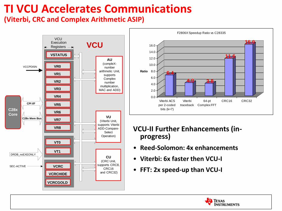
TI VCU Accelerates Communications (Viterbi, CRC and Complex Arithmetic ASIP)
VR0
VR1
VR2
VR3
VR4
VR5
VR6
VR7
VT0
VT1
CPI I/F
C28x
Core
VCCPDISN
VCU VCU
Execution
Registers
VSTATUS
DRDB_noEXEONLY
SEC-ACTIVE VCRC
VCRCHIDE
C28x Mem Bus
VR8
VCRCGOLD
AU (compleX-
number
arithmetic Unit,
supports
Complex
number
multiplication,
MAC and ADD)
VU (Viterbi Unit,
supports Viterbi
ADD-Compare-
Select
Operation)
CU (CRC Unit,
supports CRC8,
CRC16
and CRC32)
6.4
4.0 3.8
11.6
16.0
0.0
2.0
4.0
6.0
8.0
10.0
12.0
14.0
16.0
Ratio
Viterbi ACS
per 2-coded
bits (k=7)
Viterbi
traceback
64-pt
Complex FFT
CRC16 CRC32
F2806X Speedup Ratio vs C28335
VCU-II Further Enhancements (in-progress)
• Reed-Solomon: 4x enhancements
• Viterbi: 6x faster then VCU-I
• FFT: 2x speed-up than VCU-I

F2806x – New Piccolo Series
Markets: Power Line Modem, UPS, Motion and Low End Drives
105C/125C and Q100
Best mix of control peripherals Robust software libraries Code compatibility across C2000 platform ranging from
40MHz to 300MHz Increased on-chip analog integration
Serial Interfaces
Piccolo Memory
256 KB Flash
Debug
Real-Time
JTAG
100 KB RAM
Boot ROM
Power & Clocking
• Dual Osc 10 MHz
• On-Chip Osc
• Dynamic PLL Ratio
Changes
• POR
• BOR
16 ch, 2SH, 12-bit, 3 MSPS ADC
Converter
2x SPI, 1x McBSP
1x I2C
2x SCI
1x CAN
3x Comparator
Missing Clock Detection Circuitry
128-Bit Security Key/Lock
C28x 32-bit 80MHz
Peripherals Timer Modules
3x 32-bit CPU Timers
Watchdog Timer
2 x 32-bit eQEP
3 x 32-bit eCAP
8x ePWM Modules:
(8x 150ps high-res)
16x PWM outputs
FPU Unit
DMA-6CH
VCU Unit
Performance
80 MHz C28x 32-bit CPU Floating Point Unit VCU (Viterbi, Complex Math, CRC) Control Law Accelerator Full software compatibility with previous generations 6 Ch DMA
Features
Core
C28x 32-bit CPU Single cycle 32-bit MAC
80MHz Performance Floating Point Unit VCU (Viterbi, Complex Math, CRC)
Control Law Accelerator
Extra 80 MIPS Performance Floating Point
Memory Flash: 128, 256 KB RAM: 36, 68, 100 KB
Highlights Single 3.3V supply High accuracy on-chip oscillators (10MHz) Three analog comparators with 10-bit reference 150ps resolution on PWM frequency 12-bit ratio-metric ADC 2 x Quadrature Encoder Pulse (eQEP) Unit CAN 2.0B up to 16 mailboxes USB 2.0 FS Device
CLA
USB 2.0 FS Device
Packages: 80-pin LQFP*, 100-pin LQFP *USB available 1Q’11
4 x HRCAP

plcSUITE

TI plcSUITE Software Framework

TI Prime SW Stack
Fra
me
Bu
ffe
r M
an
ag
er
RTOS (DSPBIOS)
Prime MAC API Lib
TCRXM
TC Rx Manager
MRXM
MAC Rx Manager
PRXM
PHY Rx Manager
Host IF
DriverUART Driver
TCTXM
TC Tx Manager
Flow
DB
BSP Driver AFE Driver GPIO Driver
HAL API Lib
PTXM
PHY Rx Manager
PHY/MAC
Control/Data IF
Rx/Tx Sync
AGC, etc.
Prime PHY API Lib
MTXM
MAC Tx ManagerMAC/PHY IF
Control/Data
MAC/TC IF
Control/Data
Network
Manager
Conn
Manager
Access
Manager
Security
Manager
Addr
DB
Flow
Info
DB
TC/MAC IF
Control Data
Prime TC API Libosa
NET
DB
Prime Lower MAC API Lib
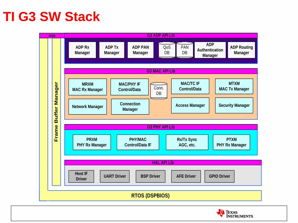
TI G3 SW Stack
Fra
me
Bu
ffer M
an
ag
er
RTOS (DSPBIOS)
G3 MAC API Lib
ADP Rx
Manager
MRXM
MAC Rx Manager
PRXM
PHY Rx Manager
Host IF
DriverUART Driver
ADP Tx
Manager
Conn.
DB
BSP Driver AFE Driver GPIO Driver
HAL API Lib
PTXM
PHY Rx Manager
PHY/MAC
Control/Data IF
Rx/Tx Sync
AGC, etc.
G3 PHY API Lib
MTXM
MAC Tx ManagerMAC/PHY IF
Control/Data
MAC/TC IF
Control/Data
Network ManagerConnection
ManagerAccess Manager Security Manager
PAN
DB
QoS
DB
ADP PAN
Manager
G3 ADP API Libosa
ADP Routing
Manager
ADP
Authentication
Manager

PLC SW Framework • Single SW Framework supporting Prime, G3, flexOFDM, (SFSK)
• RTOS (DSP BIOS) for Scheduling – Multi-threading (different priorities from deadlines): HWIs, SWIs, Task – Inter-thread communications: semaphores, mailbox message queues, mutex – OS timer: sleep, timeout callback
• PLC Functional Libraries with Standard APIs (Independent of OS or HW Platform) – PHY, MAC, CL libraries for PRIME – PHY, MAC/ADP libraries for G3 – PHY library for flexOFDM
• HAL Abstraction with Standard APIs (Same interface for discrete AFE or AFE031, F28335, F2806X) – AFE (ADC, ePWM, eCAP, DMA) – Peripherals (SPIs, UART, I2C, McBSP, GPIOs)
• Host Message Protocol (Interface to application processor)
• Embedded meter emulation application
• Enable customers to intercept at different layer as desired (e.g. at PHY layer, Host application layer), provides:
– Functional libraries – DSP application examples code: Interface to PHY – Host application example code: Interface to Host

TI plcSUITE Host Interface Messages
• >90% Common Messages
• Easy migrate from PRIME to G3 or vice versa
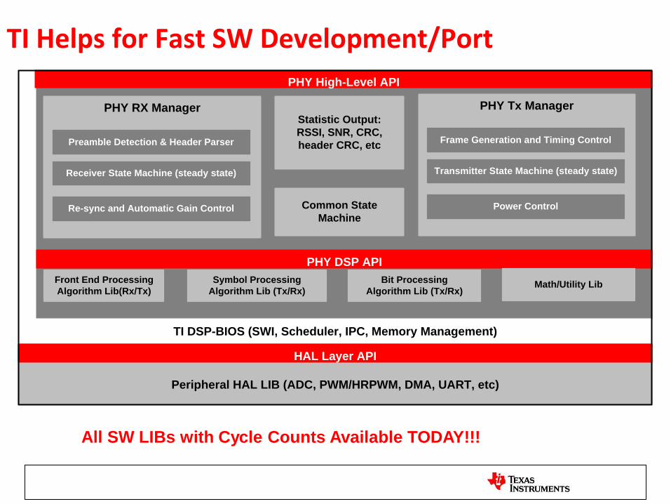
TI Helps for Fast SW Development/Port
Statistic Output:
RSSI, SNR, CRC,
header CRC, etc
PHY RX Manager
Receiver State Machine (steady state)
Preamble Detection & Header Parser
TI DSP-BIOS (SWI, Scheduler, IPC, Memory Management)
PHY High-Level API
Front End Processing
Algorithm Lib(Rx/Tx)
Symbol Processing
Algorithm Lib (Tx/Rx)
Re-sync and Automatic Gain Control
Bit Processing
Algorithm Lib (Tx/Rx)
Peripheral HAL LIB (ADC, PWM/HRPWM, DMA, UART, etc)
HAL Layer API
PHY DSP API
Math/Utility Lib
PHY Tx Manager
Transmitter State Machine (steady state)
Frame Generation and Timing Control
Power ControlCommon State
Machine
All SW LIBs with Cycle Counts Available TODAY!!!

TI PLC FlexOFDM
TI FlexOFDM Definition: Customizable OFDM
• Frequency Band/Bandwith Flexibility: – Any frequency channel: 0-500KHz, Any channel BW (today limited to 12KHz)
– Automatic channel scan for channel quality measurement and monitor
– Flexible Analog Front End: AFE031, AFE032, AFE033
• Flexible PHY Layer: Best of G3/PRIME and more … – Fully automated adaptive tone map and tone mask (P1901.2 contribution)
– Coherent modulation with pilots embedded (P1901.2 optional feature)
– Provision for longer preamble sequence for harsh line condition
– Optional more repetitions in the header
– Configurable block inter-leaver sizes
– Zero-Crossing interference cancellation
– Others to come
• Flexible MAC Layer: Best of G3/PRIME/802.15.4e and more – CSMA/CA baseline
– Customizable GTS schedule for multiple applications: DC-DC msg/SEP2.0
– Multiple routing (AODV, LOAD, RPL, etc): p2p/p2mp, star, tree, mesh
– Closely coupled with PHY FlexOFDM PHY features: ATM, etc.
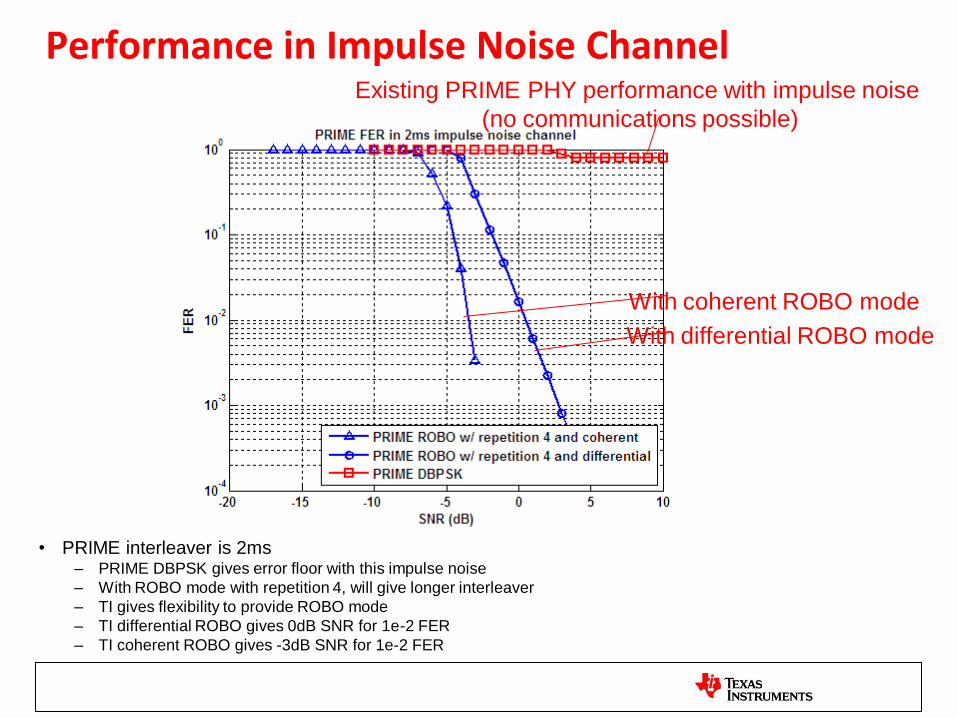
Performance in Impulse Noise Channel
• PRIME interleaver is 2ms – PRIME DBPSK gives error floor with this impulse noise
– With ROBO mode with repetition 4, will give longer interleaver
– TI gives flexibility to provide ROBO mode
– TI differential ROBO gives 0dB SNR for 1e-2 FER
– TI coherent ROBO gives -3dB SNR for 1e-2 FER
Existing PRIME PHY performance with impulse noise
(no communications possible)
With differential ROBO mode
With coherent ROBO mode
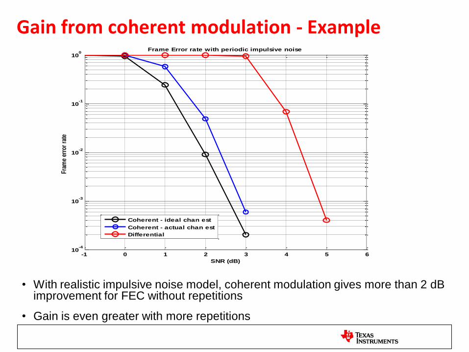
Gain from coherent modulation - Example
• With realistic impulsive noise model, coherent modulation gives more than 2 dB improvement for FEC without repetitions
• Gain is even greater with more repetitions
-1 0 1 2 3 4 5 610
-4
10-3
10-2
10-1
100
Fram
e er
ror
rate
SNR (dB)
Frame Error rate with periodic impulsive noise
Coherent - ideal chan est
Coherent - actual chan est
Differential
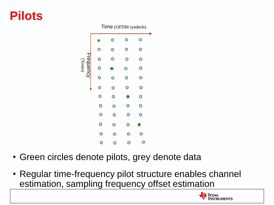
Pilots
• Green circles denote pilots, grey denote data
• Regular time-frequency pilot structure enables channel estimation, sampling frequency offset estimation
Time (OFDM symbols)
Fre
quency
(To
nes)

Pilots+coherent modulation + more reptitions Better header performance
• Enables header decoding below -5 dB even with realistic crystals
-10 -5 0 5 10 15 2010
-2
10-1
100
SNR (dB)
FE
R
QPSK with rep 12 FER with residual sampling frequency offset in AWGN channel
Pilot based (50ppm)
Preambled based (2 preamble used, 50ppm)
Pilot based (200ppm)
Preamble based (2 preambles used, 200ppm)
Pilot based (100ppm)
Preamble based (2 preambles used, 100ppm)
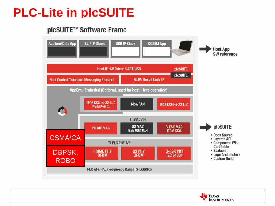
PLC-Lite in plcSUITE
DBPSK,
ROBO
CSMA/CA

FlexLite/FSK Comparison (1)
• AWGN performance: OFDM performance in all white Gaussian noise (AWGN) 7dB better than FSK – FSK has to inject 2 times the signal amplitude compared to OFDM to get same
performance
Standards: Multiple PLC standards are using OFDM – PRIME, G3, ITU G.9955, ITU G.hnem/IEEE1901.2
FlexLite/FSK comparison (2)
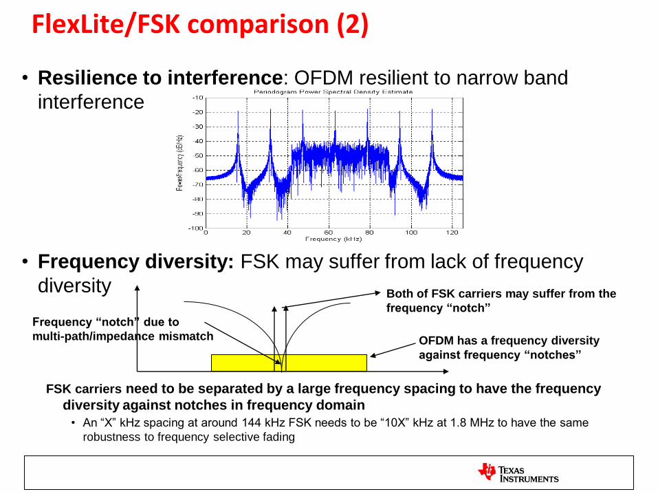
• Resilience to interference: OFDM resilient to narrow band
interference
• Frequency diversity: FSK may suffer from lack of frequency
diversity
FSK carriers need to be separated by a large frequency spacing to have the frequency
diversity against notches in frequency domain
• An “X” kHz spacing at around 144 kHz FSK needs to be “10X” kHz at 1.8 MHz to have the same
robustness to frequency selective fading
OFDM has a frequency diversity
against frequency “notches”
Frequency “notch” due to
multi-path/impedance mismatch
Both of FSK carriers may suffer from the
frequency “notch”
TI PLC Standard Activities

OFDM PLC Alliances and International Standards
• G3 Alliance – EDF/ERDF + 3 SC vendors + 3 meter manufacturers
– Cenelec A and FCC 145.3 – 478 KHz. LV/MV network
– Interoperability, mesh network , band plan in discussion
– Full scale deployment on French grid in 2014-2015. Worldwide applicability
• PRIME Alliance – Iberdrola + 3 SC vendors + 3 meter manufacturers
– CENELEC A band, LV access network
– PHY and MAC are stable. Tree topology, adding PHY ROBO mode for impulse noise
– Full scale deployment on Iberdrola grid in 2012-2013. Worldwide applicability.
• IEEE P1901.2
– Interoperable with G3 Cenelec A and G3 FCC. Band plans: Cen A, Cen B, FCC 145.3-478 KHz
– Sub-banding, coherent modulation, mesh network, beaconing, channel models, coexistence in discussion.
– Draft in progress. International standard expect in 2012
• ITU-T G.hnem
– Coherent modulation, synchronous beacons, full FCC band, robust preamble, MV/LV
– Not interoperable with G3 although G3 and PRIME Cen A are G.hnem Annexes
– Draft complete. International standard in 2012.
• SAE J2931-3 (EV – EVSE communications)
– Based on G3 (TI/Maxim). Band plan: Cen B/C/D and full FCC
– EMC testing completed at Ford. Testing at EPRI and DOE in August 2011. IPv6. 6lowPAN, SEP2.0 supported.
• ISO / IEC JWG CI for EV PLC, IEC 15118-3
– HomePlug Green PHY and G3/P1901.2 are under consideration.
– European automakers leaning towards HPGP, but auto qualified production chipsets not available

TI active participation in the Smart Grid Initiatives
15.4G
PAP15

TI Standard Participation & Contribution
• TI Contributes to IEEE, ITU, and ISO standards
• TI Participates in Industry Alliances – PRIME, G3, WiFi-WFA, Zigbee, others
• TI ITU-T G.hnem Accepted Contributions – Pilots and coherent modulation: TI proposed add pilots to enable coherent modulation
– Interleaver: TI proposed block interleavers of length at most 10 ms (half of zero crossing)
– FEC: TI proposed concatenated coding as opposed to LDPC
– Tone spacing: TI proposed changing to multiple of PRIME / G3 tone spacings
– Preamble structure: TI proposed adding channel estimation symbols to aid in synchronization
• TI P1901.2 Technical Contributions: – Pilots – TI proposed adding pilots to enable coherent modulation
– Beacon – TI proposed adding optional beacon mode with multiple beacon slots and CAP slots
– PHY operation in multiple tone masks – TI proposed defining PHY operation in multiple tone masks
– Channel modeling for A/B/C/D band parameters – TI lead channel model work
– MAC operation in multiple tone masks – TI proposed multiple-tone mask operation in the MAC, combining ideas in 15.4 beacon mode with other features. Under discussion
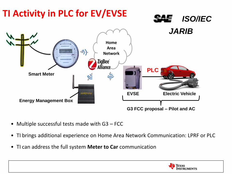
TI Activity in PLC for EV/EVSE
• Multiple successful tests made with G3 – FCC
• TI brings additional experience on Home Area Network Communication: LPRF or PLC
• TI can address the full system Meter to Car communication
Smart Meter
Home Area
Network
Electric Vehicle EVSE
PLC
G3 FCC proposal – Pilot and AC
ISO/IEC
JARIB
Energy Management Box
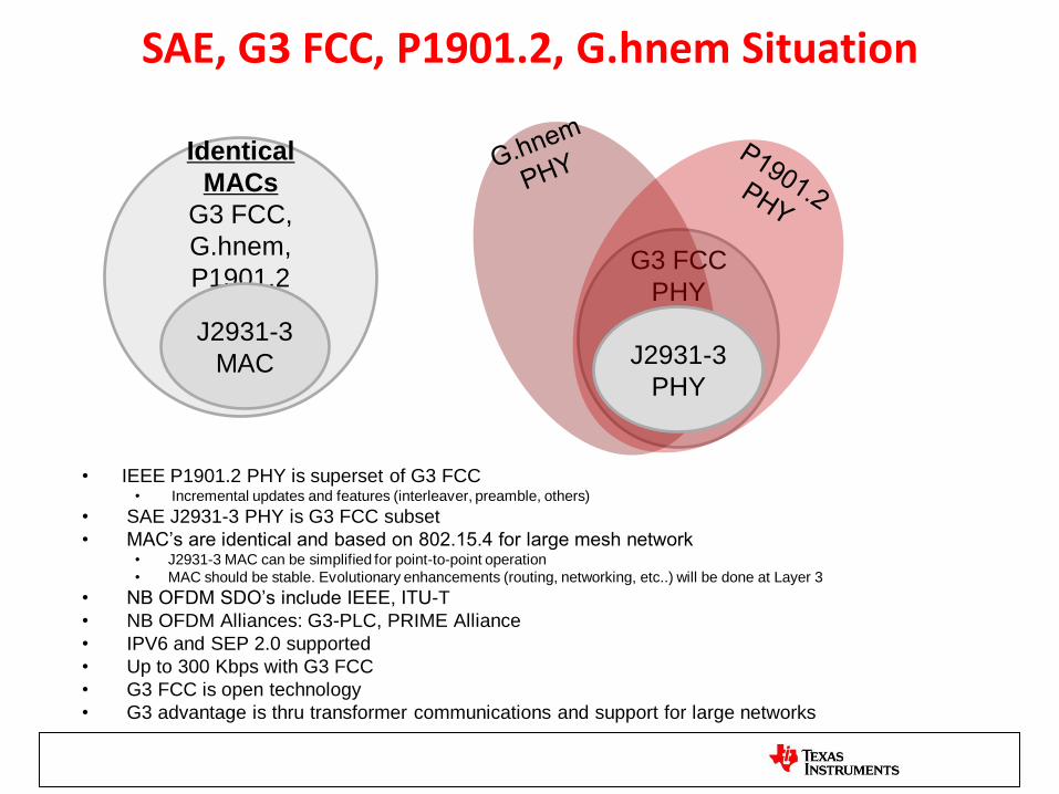
SAE, G3 FCC, P1901.2, G.hnem Situation
• IEEE P1901.2 PHY is superset of G3 FCC • Incremental updates and features (interleaver, preamble, others)
• SAE J2931-3 PHY is G3 FCC subset
• MAC’s are identical and based on 802.15.4 for large mesh network • J2931-3 MAC can be simplified for point-to-point operation
• MAC should be stable. Evolutionary enhancements (routing, networking, etc..) will be done at Layer 3
• NB OFDM SDO’s include IEEE, ITU-T
• NB OFDM Alliances: G3-PLC, PRIME Alliance
• IPV6 and SEP 2.0 supported
• Up to 300 Kbps with G3 FCC
• G3 FCC is open technology
• G3 advantage is thru transformer communications and support for large networks
Identical
MACs
G3 FCC,
G.hnem,
P1901.2
G3 FCC
PHY
J2931-3
PHY
J2931-3
MAC

TI PLC Field Test Experience

Field Test Scenarios
• LV side of transformer to eMeter
• Crossing MV/LV transformer(s) to eMeter
• Street Lighting applications
• Solar applications
• Electrical Vehicle(EV) to Electrical Vehicle Service Entity (EVSE) Communications

TI PLC Field Tests For last 180 Days Where When Band/NW Software Results
Southern US
May 2010 CENELEC-A
LV/MV
PRIME+ROBO Channel and noise in Cenelec band
Japan Aug 2010 CENELEC-A +
FCC, MV/LV
PRIME+ROBO+subband Cenelec + FCC band demonstration with cap bank
Southern US Nov 2010 FCC, MV/LV PRIME+ROBO+subband Good SNR for MV-MV comm
MV/LV and LV/MV communication do not have enough SNR to
support communication on entire FCC / ARIB bandwidth Central Indiana Dec 2010 FCC, MV/LV PRIME+ROBO+subband
Milan Feb 2011 CENELEC-A,
LV/LV
PRIME+ROBO Passed all the LV/LV test cases
Milwaukee, WI Mar 2011 CENELEC-A+FCC,
MV/LV
G3-CENELEC A +flex
OFDM
Passed with the erasure channel with actuators
Southern US Mar 2011 FCC, LV/LV,
LV/MV
G3-FCC with flexible
masks
Channel and noise captures
Confirm flexOFDM tests about insufficient SNR
Hiroshima, Japan April 2011 FCC, LV/LV G3-FCC with flexible
masks
Passed all the LV/LV test cases except the WHT case.
Beijing, China Apr 2011 FCC, LV/LV G3-FCC with flexible
masks
Achieved up to 200m in out-door grid to meter tests
Challenges in in-door tests
Spain 2011 CENELEC-A,
LV/LV
PRIME Official field deployment for hundreds of meters
Mexico City, Mexico May 2011 CENELEC+FCC,
LV/LV
PRIME and G3-FCC Successfully pass 2 circuit-breakers for G3-FCC, PRIME has
difficulty
Turkey June 2011 CENELECA, LV/LV PRIME & G3-CENELC Successfully pass all test cases competitor either pass or fail
49

TI PRIME Based 220 Meters in Burriana, Spain
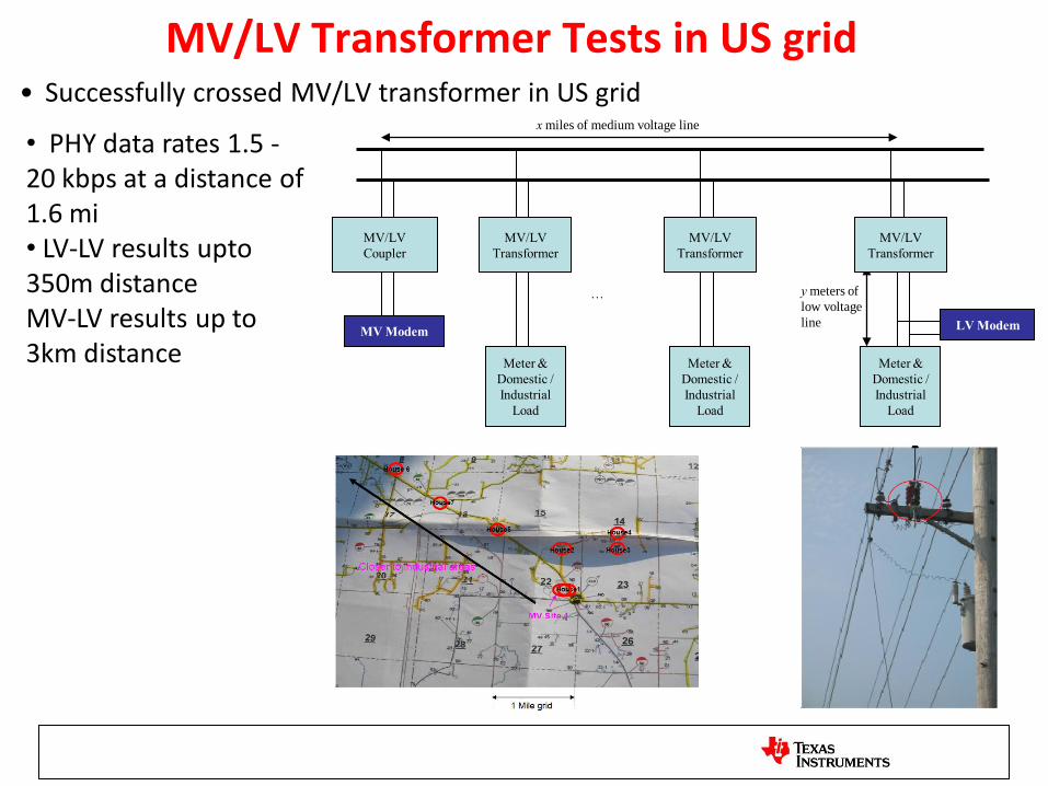
MV/LV Transformer Tests in US grid • Successfully crossed MV/LV transformer in US grid
MV/LV
Coupler
x miles of medium voltage line
MV Modem
MV/LV
Transformer
Meter &
Domestic /
Industrial
Load
MV/LV
Transformer
Meter &
Domestic /
Industrial
Load
LV Modem
y meters of
low voltage
line
MV/LV
Transformer
Meter &
Domestic /
Industrial
Load
…
• PHY data rates 1.5 - 20 kbps at a distance of 1.6 mi • LV-LV results upto 350m distance MV-LV results up to 3km distance
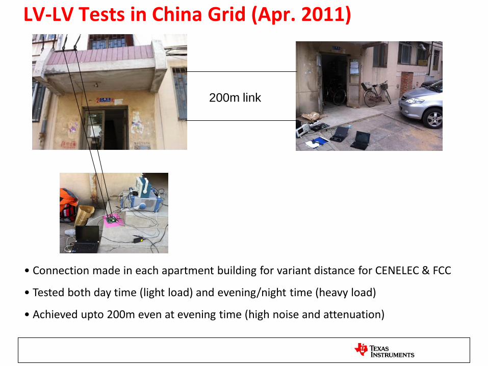
LV-LV Tests in China Grid (Apr. 2011)
200m link
• Connection made in each apartment building for variant distance for CENELEC & FCC
• Tested both day time (light load) and evening/night time (heavy load)
• Achieved upto 200m even at evening time (high noise and attenuation)
53
Mexico LV-LV Test (April, 2011) Modem1
Modem3
40m
50m
70m
Additional
Load
Load CEN A (40-90kHz) CEN A with tone mask
(40-90kHz with 60-
77kHz not transmitting)
CEN B (98-
122kHz)
CEN B/C (98-
138kHz)
FCC Low (145kHz-
310kHz)
FCC High (310-
478kHz)
Normal
Load
ROBO: 0% FER
DBPSK: 100%FER
ROBO: 0% FER
DBPSK: 100% FER
ROBO: 0% FER
DBPSK: 50% FER
ROBO: 0% FER
DBPSK: 0% FER
DQPSK: 10% FER
ROBO: 0% FER
DBPSK: 100%
FER
ROBO: 0% FER
DBPSK: 100%
FER
Additional
Load
N/A N/A N/A ROBO: 0% FER
DBPSK: N/A
N/A N/A

Japan – Mar 2011
• Test G3-FCC PHY communication between two modem separated by 100m, with three switchable taps at 25, 50, 75m from AC room
– Noisy load equipment can be connected to taps. Typical load tried = space heater “Kotatsu”
• Many switchable loads at receiver in Room 2 – plate heater, space heater, microwave oven, TV, DVD player, …
• Results from tests using TI G3-FCC modems – Adding load equipment at Room 2 is the main challenge (tap loads impact SNR, but effect of loads in Room 2 more
dramatic) – G3-FCC with 168.75 kHz bandwidth offers good performance for most loads, except for the case of IHT-only load – For IHT-only load, G3-FCC with 93.75 kHz bandwidth offers good performance – Reverse direction (room 2 -> AC room) is good for all loads tested. No problems with thermal shutdown
AC room Closed room for setting
up modem and test
equipment powered by
separate LV line
Modem 1
MV/LV
Trans-
former
Noisy Load 1
Noisy Load 2
Noisy Load 3
Room 2 Closed room with multiple switchable loads
Separate LV supply for test equipment to
avoid loading
Modem 2

LV-LV Tests in Turkey
• Lab tests
– With 200m extension cable, 34kbps achieved with G3 DQPSK
– With 200m extension cable and contact noise (with hair dryer, etc), 34kbps
achieved with G3 DQPSK
• Factory tests
– With 350m distance, 20kbps achieved with PRIME DBPSK (Factory
machine off)
– With 350m distance, 20kbps achieved with PRIME DBPSK (Factory
machines on)
• File transfer is also ok

Street Lighting Applications
(1) Ckt 12, AC to AC
21kbps at ~1200ft
Courtesy of Google
• Ckt breaker 12, phase AC to AC, was tested in CENELEC A band (PRIME)
21kbps at ~1200ft
• Ckt 17 phase BC to Ckt 12 phase AC was tested in FCC band (170-184 kHz)
10kbps at ~4000ft (=1.2km)
Circuit breaker room that feed light poles
(2) Ckt 17, BC to Ckt
12 AC, 10 kbps at
~4000ft
12
12
17
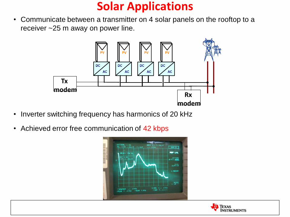
Solar Applications • Communicate between a transmitter on 4 solar panels on the rooftop to a
receiver ~25 m away on power line.
• Inverter switching frequency has harmonics of 20 kHz
• Achieved error free communication of 42 kbps
Tx modem
Rx modem
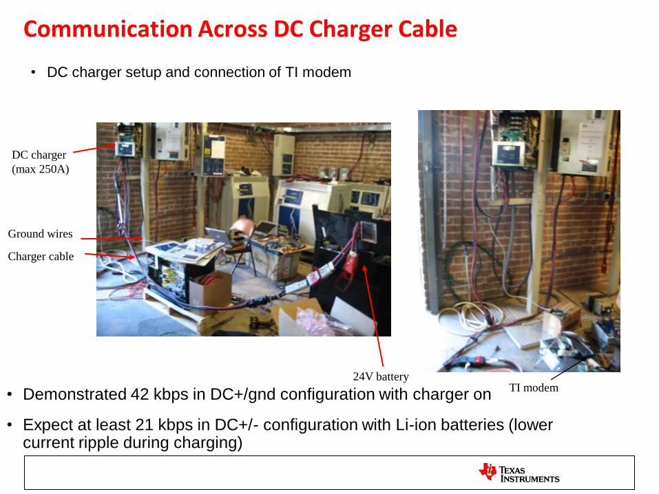
Communication Across DC Charger Cable
• DC charger setup and connection of TI modem
Charger cable
Ground wires
DC charger
(max 250A)
24V battery TI modem
• Demonstrated 42 kbps in DC+/gnd configuration with charger on
• Expect at least 21 kbps in DC+/- configuration with Li-ion batteries (lower current ripple during charging)

TI PLC Certification and Lab Test
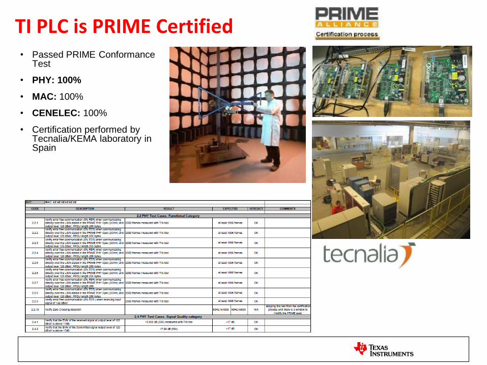
TI PLC is PRIME Certified • Passed PRIME Conformance
Test
• PHY: 100%
• MAC: 100%
• CENELEC: 100%
• Certification performed by Tecnalia/KEMA laboratory in Spain

PRIME Certification Procedures
• Test Categorices:
– EMC
– PHY
– MAC
– CS Layers
G3 Certification Procedures
• WS3 Focuses on PHY Interoperability Test Process
– Tests of the digital part of the PHY layer at the simulator level
– Tests of the complete PHY layer at the simulator level
– Plug fest
• ERDF Technical Lab Tests
– PHY Tests
– Data Link Layer Tests
– Upper Layer Tests
• PHY Tests Example
– Conformance to standard
– Dynamic range
– Harmonics measurements
– Robustness against impulse noise
– Robustness against white noise
– Robustness against sinusoidal noise
– ….

Base Node
Service Node 1 Service Node 2
Service Node 3
Att 2
Service Node 4
Att 3
Att 1
Network Registration Test
63
Base Node
Service Node 1 Service Node 2 Service Node 3
Service Node 4
Base Node
Service Node 1
Service Node 2
Att 1
Att 2
Service Node 3
Service Node 4
Att 3
Att 4
Linear Chain Network
Hybrid Network
Single Hop Network
Network registration test for the following scenarios were performed successfully
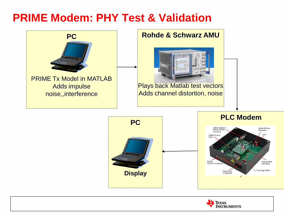
PC
PRIME Tx Model in MATLAB
Adds impulse
noise,,interference
PRIME Modem: PHY Test & Validation
Rohde & Schwarz AMU
Plays back Matlab test vectors
Adds channel distortion, noise
AMU operation
PLC Modem
Add photo
)
PC
Display
PHY Validation
MATLAB
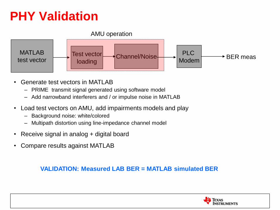
test vector Test vector
loading Channel/Noise
PLC
Modem BER meas
AMU operation
• Generate test vectors in MATLAB
– PRIME transmit signal generated using software model
– Add narrowband interferers and / or impulse noise in MATLAB
• Load test vectors on AMU, add impairments models and play
– Background noise: white/colored
– Multipath distortion using line-impedance channel model
• Receive signal in analog + digital board
• Compare results against MATLAB
VALIDATION: Measured LAB BER = MATLAB simulated BER
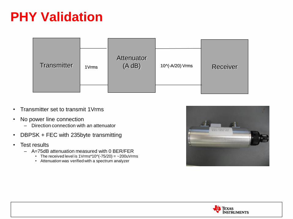
PHY Validation
Transmitter Attenuator
(A dB)
Receiver 1Vrms 10^(-A/20) Vrms
• Transmitter set to transmit 1Vrms
• No power line connection – Direction connection with an attenuator
• DBPSK + FEC with 235byte transmitting
• Test results – A=75dB attenuation measured with 0 BER/FER
• The received level is 1Vrms*10^(-75/20) = ~200uVrms • Attenuation was verified with a spectrum analyzer
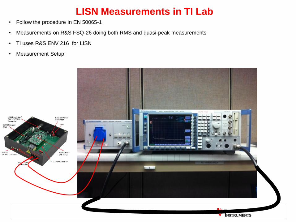
LISN Measurements in TI Lab • Follow the procedure in EN 50065-1
• Measurements on R&S FSQ-26 doing both RMS and quasi-peak measurements
• TI uses R&S ENV 216 for LISN
• Measurement Setup:

Network Validation
• Data Concentrator
• Meters
• Multi-level Network
– Registration
– Connection
– Long/short Cycle Test
– Firmware Upgrade
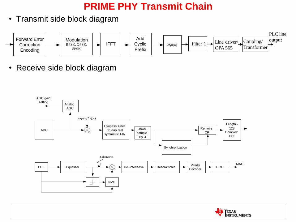
PRIME PHY Transmit Chain
• Transmit side block diagram
• Receive side block diagram
Modulation BPSK , QPSK ,
8 PSK
IFFT
Add
Cyclic
Prefix
Forward Error
Correction
Encoding PWM
Line driver/
OPA 565
Coupling/
Transformer
PLC line
output Filter 1
ADC
Lowpass Filter
11 - tap real
symmetric FIR
exp ( - j 2 p f c k )
Down -
sample
By 4
Remove
CP
Length -
128 Complex
FFT
Synchronization
Analog
AGC
AGC gain
setting
Descrambler De - interleave Viterbi
Decoder CRC Equalizer
NVE
FFT
Soft metric
MAC
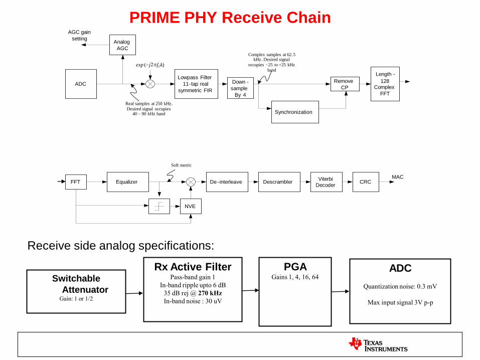
PRIME PHY Receive Chain
Rx Active Filter Pass-band gain 1
In-band ripple upto 6 dB
35 dB rej @ 270 kHz
In-band noise : 30 uV
PGA Gains 1, 4, 16, 64
ADC
Quantization noise: 0.3 mV
Max input signal 3V p-p
Switchable
Attenuator Gain: 1 or 1/2
Receive side analog specifications:
ADC
Lowpass Filter
11 - tap real
symmetric FIR
exp ( - j 2 p f c k )
Down -
sample
By 4
Remove
CP
Length -
128 Complex
FFT
Synchronization
Real samples at 250 kHz . Desired signal occupies
40 – 90 kHz band
Complex samples at 62 . 5 kHz . Desired signal
occupies - 25 to + 25 kHz band
Analog
AGC
AGC gain
setting
Descrambler De - interleave Viterbi
Decoder CRC Equalizer
NVE
FFT
Soft metric
MAC


