TEXT OF PROPOSED AMENDMENT TO INTERNATIONAL STANDARDS AND RECOMMENDED PRACTICES ANNEX 10 AERONAUTICAL TELECOMMUNICATIONS VOLUME III – COMMUNICATION SYSTEMS TO THE CONVENTION ON INTERNATIONAL CIVIL AVIATION TABLE OF CONTENTS CHAPTER 13 L-Band Digital Aeronautical Communications System (LDACS)...........................3 13.1 Definitions ............................................................................................................................... 2 13.2 Introduction ............................................................................................................................. 3 13.3 General .................................................................................................................................... 3 13.4 Radio Frequency (RF) Characteristics .................................................................................... 5 13.5 System Characteristics of the Airborne Installation .............................................................. 10 13.6 System Characteristics of the Ground Installation ................................................................ 10 13.7 LDACS Signaling Structure .................................................................................................. 11 13.8 Performance Requirements ................................................................................................... 13 13.9 System Interfaces .................................................................................................................. 15 13.10 Application Requirements ................................................................................................. 15
Transcript
TEXT OF PROPOSED AMENDMENT TO
INTERNATIONAL STANDARDS AND RECOMMENDED PRACTICES
ANNEX 10
AERONAUTICAL TELECOMMUNICATIONS
VOLUME III –
COMMUNICATION SYSTEMS
TO THE CONVENTION ON INTERNATIONAL CIVIL AVIATION
TABLE OF CONTENTS
CHAPTER 13 L-Band Digital Aeronautical Communications System (LDACS)...........................3
CHAPTER 13 L-Band Digital Aeronautical Communications System (LDACS)
Insert new text as follows
INITIAL PROPOSAL 1
13.1 DEFINITIONS
Airborne station (AS). A station in the mobile service, usually an aircraft, intended to connect to the ground station. Alternative positioning, navigation, and timing (APNT). A means for positioning, navigation, and timing working independently of global navigation satellite systems. Bit error ratio (BER). The number of bit errors in a sample divided by the total number of bits in the sample, generally averaged over many such samples. Channel assignment. A logical assignment of forward link and reverse link center frequencies programmed to the ground station. Forward link (FL). The transmission direction from the ground station to the airborne station. Frequency division duplex (FDD). A duplex scheme where forward and reverse link transmissions occur at different frequencies but may occur simultaneously in time. Ground station (GS). A generalized equipment set providing connectivity, management, and control of the airborne stations. L-band Digital Aeronautical Communications System (LDACS). A high capacity data link supporting mobile communications in all airspace, i.e. en-route, terminal airspace, and airports. LDACS handover. The process in which an LDACS airborne station migrates from the air-interface provided by one LDACS ground station to the air-interface provided by another LDACS ground station. Orthogonal frequency-division multiplexing (OFDM). OFDM is a multi-carrier transmission technique. The signal is distributed over a large number of orthogonal sub-carrier waves each individually modulated at low bandwidth. Peak-to-average power ratio (PAPR). The ratio between peak power and average power of a transmission signal. Required Communications Performance (RCP). The set of system performance parameters that are required for a communication system to support a communication application. Required Surveillance Performance (RSP). The set of system performance parameters that are required for a surveillance system to support a surveillance application.
A-3
Reverse link (RL). The transmission direction from the airborne station to the ground station. Origin: CP
Rationale: The above definitions are specific to the L-band Digital Aeronautical Communications System and are provided in addition to the general definitions given in Chapter 1, Part 1 of Annex 10 Volume III.
INITIAL PROPOSAL 2
13.2 INTRODUCTION
Note 1.— L-band Digital Aeronautical Communications System (LDACS) is a high-capacity data link supporting mobile communications, related to the safety and regularity of flight, in all airspace, i.e. en-route, terminal airspace, and airports.
Note 2.— LDACS is a 4G technology derivative with adaptations to meet a) compatibility requirements to ensure coexistence with other aeronautical systems operating in L-band and b) in flight communication service requirements for ATS Baseline 3 (ATS-B3) as well as other critical services including Aeronautical Operational Communications (AOC).
Note 3.— These SARPs list features which are mandatory for interoperability of LDACS equipment. Details are provided in the accompanying Manual which is Document 10114 entitled "Manual on L-band Digital Aeronautical Communications System".
13.3 GENERAL
13.3.1 LDACS shall conform to the requirements of this and the following chapters.
13.3.2 LDACS shall support aeronautical mobile (route) service (AM(R)S) communications.
13.3.3 LDACS shall support air-ground communications.
13.3.4 Recommendation.— LDACS should support air-air communications.
Note 1.— These SARPs describe the air-ground mode of LDACS only. However, these SARPs already take provision that extension towards the air-air mode could be implemented via software update without the necessity for major hardware adaptations.
Note 2.— The "should" in Paragraph 13.3.4 will become a "shall" as soon as an agreed LDACS specification for air-air communications is available.
13.3.5 LDACS shall support communications between LDACS ground station (GS) and LDACS airborne station (AS) at distances of up to 200 NM in regular range mode.
Note.— The coverage area of an LDACS GS in regular range mode is adjusted to operational needs and might differ from GS to GS. Especially, the coverage area might be smaller than 200 NM.
A-4
13.3.6 Recommendation.— LDACS should support communications between LDACS GS and LDACS AS at distances of up to 400 NM in extended range mode.
Note 1.— Where required the coverage area of an LDACS GS might be extended applying the extended range mode. This extension might be achieved through use of directional antennas.
Note 2.— Special consideration have to be taken to the radio horizon achievable when applying the extended range mode. To achieve a large radio horizon, the LDACS GS needs to be placed at a respective height or on a high-altitude platform.
Note 3.— The coverage area of an LDACS GS in extended range mode is adjusted to operational needs and might differ from GS to GS. Thus, the coverage area might be between 200 NM and 400 NM.
Note 4.— Usually, the coverage area of an LDACS GS in extended range mode is highly asymmetrical.
Note 5.— Each LDACS GS signals the supported range mode.
13.3.7 LDACS shall support a ranging functionality which allows an LDACS AS to determine pseudo-ranges to LDACS GSs.
13.3.8 LDACS shall support multiple levels of message priority.
13.3.9 LDACS shall process messages according to their associated priority.
13.3.10 LDACS shall support point to point communication on forward link (FL) and reverse link (RL).
13.3.11 LDACS shall support broadcast on FL.
13.3.12 LDACS shall support multiple service flows simultaneously.
13.3.13 LDACS shall support handover between different LDACS GS during AS movement or on degradation of connection with current ground station.
13.3.14 LDACS shall support the global network mobility solution in a multilink environment.
13.3.15 LDACS shall support a flexible implementation architecture to permit link and network layer functions to be located in different or same physical entities.
13.3.16 LDACS shall support adaptive coding and modulation.
13.3.17 LDACS shall be able to operate properly when the LDACS AS moves with a speed of up to 850 knots relative to the LDACS GS.
Note 1.— The relative movement between GS and AS induces frequency shifts due to the Doppler effect.
Note 2.— Considering the air-air mode of LDACS, the value for the relative velocity has to be doubled, since both LDACS transmitter and LDACS receiver are moving in this case.
13.3.18 LDACS shall keep total accumulated interference levels with limits defined by the International Telecommunication Union – Radiocommunication Sector (ITU-R) as required by national/international rules on frequency assignment planning and implementation.
Note.— When providing AM(R)S, an AM(R)S system shall operate only in frequency bands which are appropriately allocated to AM(R)S and protected by the ITU Radio Regulations.
13.3.19 LDACS shall limit its maximum equivalent isotropic radiated power (EIRP) as defined in the ITU-R resolution RES417.
13.3.20 LDACS implementation and deployment shall ensure that existing aviation systems in L-band are not harmfully interfered.
A-5
13.3.21 LDACS shall support internet protocol (IP) packet data services.
13.3.22 LDACS shall provide mechanisms to transport Aeronautical Telecommunication Network / Internet Protocol Suite (ATN/IPS) and Aeronautical Telecommunication Network / Open Systems Interconnection over IP (ATN/OSI over IP) based communication services.
Note 1.— The Manual on the Aeronautical Telecommunication Network (ATN) using Internet Protocol Suite (IPS) Standards and Protocols (Doc 9896) provides additional information about ATN/IPS based communication.
Note 2.— The Manual on Technical Specifications for ATN using ISO/OSI Standards and Protocols (Doc 9880) provides additional information about ATN/OSI based communication.
13.3.23 LDACS shall support voice services.
Origin: CP
Rationale: The sections above describe the basic function and purpose of the L-band Digital Aeronautical Communications System.
INITIAL PROPOSAL 3
13.4 RADIO FREQUENCY (RF) CHARACTERISTICS
13.4.1 General Radio Characteristics
13.4.1.1 LDACS shall operate in frequency division duplex (FDD) mode.
13.4.1.2 LDACS shall operate with a 500 kHz channel spacing on both FL and RL.
13.4.1.3 LDACS antenna polarization shall be vertical for both AS and GS antenna.
13.4.1.4 LDACS shall operate without guard bands between adjacent LDACS channels.
13.4.1.5 LDACS co-channel interference rejection shall be at least 14 dB.
Note 1.— This corresponds to a frequency reuse factor of 7. Note 2.— The figure for co-channel interference rejection ensures that at least all adaptive
coding and modulation types involving QPSK modulation fulfill the required bit-error ratio (BER).
13.4.2 Frequency Bands
13.4.2.1 LDACS equipment shall be capable of operating in the frequency band from 960 to 1164 MHz with channel spacing of 500 kHz.
13.4.2.2 LDACS FL shall be assigned to the frequency band 1110 – 1156 MHz.
13.4.2.3 LDACS RL shall be assigned to the frequency band 964 – 1010 MHz.
13.4.2.4 LDACS channel assignment within the FL and RL frequency band shall be performed according to ITU radio regulations.
A-6
13.4.2.5 LDACS duplex spacing between the LDACS FL and RL frequency bands shall be 146 MHz.
Note.— There is no fixed assignment between the forward link channels and the revers link channels. This allows a dynamic allocation of FL and RL channels, which gives more flexibility for deploying LDACS.
13.4.2.6 LDACS nominal frequency of both FL and RL channels shall lie on a 500 kHz grid.
13.4.2.7 LDACS FL and RL channels shall have a unique channel number.
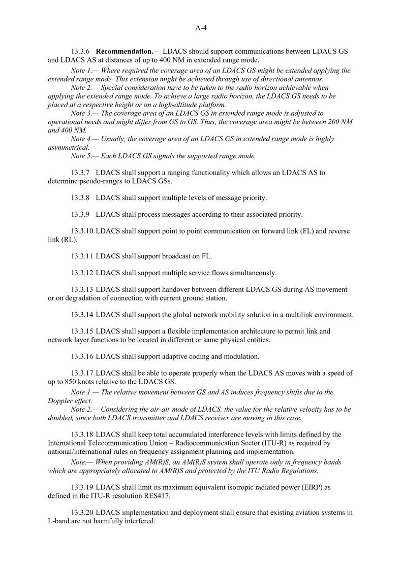
13.4.2.8 LDACS channel LC#n shall operate at a center frequency (DC subcarrier) as defined in Table 13.4-1.
Note.— Table 13.4-1 shows the mapping of all LDACS channels to frequencies.
Table 13.4-1: LDACS channel assignment
LDACS Channel Center Frequency LC#0 960.0 MHz LC#1 960.5 MHz LC#2 961.0 MHz
… … LC#8 964.0 MHz
… … LC#100 1010 MHz
… … LC#330 1125 MHz
… … LC#392 1156 MHz
… … LC#408 1164.0 MHz
13.4.3 Radiated Power
13.4.3.1 LDACS AS equipment shall be able to generate a transmit power of 42 dBm averaged over continuous RL transmissions and measured directly at the transmitter output.
13.4.3.2 The maximum EIRP of an LDACS AS averaged over continuous RL transmissions shall be 41 dBm.
Note 1.— In defining the maximum EIRP, 42 dBm transmit power, 3 dB cable loss,1 dB duplexer loss as well as 3 dBi antenna gain is assumed.
Note 2.— The maximum EIRP is required to support communications up to the maximum coverage.
13.4.3.3 LDACS AS shall implement power control.
Note.— Power control is required to reduce the transmit power of the LDACS AS equipment to adjust the transmit power according to the distance to the LDACS GS.
13.4.3.4 LDACS AS power control shall have a dynamic range not less than 50 dB.
13.4.3.5 LDACS AS peak-to-average power ratio (PAPR) shall not exceed 11 dB measured directly at the transmitter output.
13.4.3.6 LDACS GS equipment shall be able to generate a transmit power of 42 dBm averaged over continuous FL transmissions and measured directly at the transmitter output.
A-7
13.4.3.7 The maximum EIRP of an LDACS GS in regular range mode averaged over continuous FL transmissions shall be 52 dBm.
Note 1.— In defining the maximum EIRP, 42 dBm transmit power, 2 dB cable loss as well as 12 dBi antenna gain is assumed.
Note 2.— The actual EIRP used of an LDACS GS in regular range mode might be smaller depending on the coverage area of the LDACS GS.
13.4.3.8 The maximum EIRP of an LDACS GS in extended range mode averaged over continuous FL transmissions shall be 58 dBm.
Note 1.— In defining the maximum EIRP, 42 dBm transmit power, 2 dB cable loss as well as 18 dBi antenna gain is assumed.
Note 2.— The actual EIRP used of an LDACS GS in extended range mode might be smaller depending on the coverage area of the LDACS GS.
13.4.3.9 LDACS GS PAPR shall not exceed 11 dB measured directly at the transmitter output.
13.4.4 Minimum Receiver Sensitivity
13.4.4.1 LDACS minimum receiver sensitivity depends on the chosen coding and modulation scheme and shall comply with Table 13.4-2.
Note 1.— The computation of the sensitivity level for LDACS is described in the accompanying Manual Document 10114.
Note 2.— The sensitivity level is defined as the power level measured at the receiver input when the bit error ratio (BER) is equal to 1 × 10⁻⁶ and all active sub-carriers are transmitted in the channel. In general, the requisite input power depends on the number of active sub-carriers of the transmission.
Note 3.— The sensitivity values in Table 13.4-1 assume a receiver noise figure of 6 dB. Note 4.— The sensitivity values in Table 13.4-2 assume absence of any source of interference
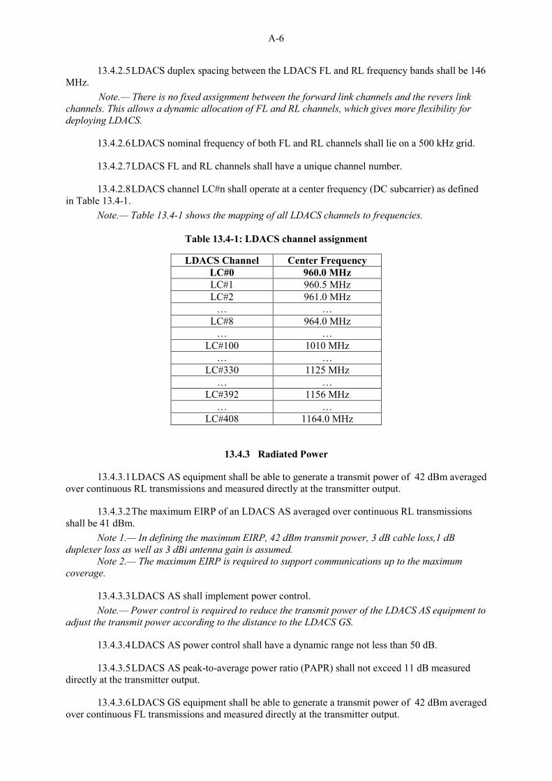
13.4.5.1 LDACS receiver selectivity shall comply with Table 13.4-3 and Figure 13.4-1.
Note.— The receiver selectivity values comprise the complete LDACS receiver chain after the duplexer, i.e. the duplexer is not included.
Table 13.4-3: LDACS receiver selectivity values
Passband Ripple (±250 kHz) within ± 1 dB Attenuation @ ±300 kHz > 6 dB
A-8
Attenuation @ ±400 kHz > 40 dB Attenuation @ ±500 kHz > 70 dB Attenuation @ ±750 kHz > 80 dB Attenuation @ ±1500 kHz > 90 dB
Figure 13.4-1: LDACS receiver selectivity.
13.4.6 Spectral Mask and Emissions
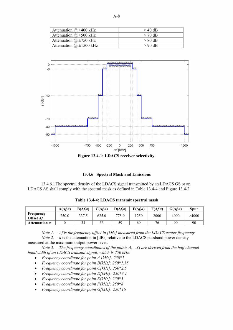
13.4.6.1 The spectral density of the LDACS signal transmitted by an LDACS GS or an LDACS AS shall comply with the spectral mask as defined in Table 13.4-4 and Figure 13.4-2.
Note 1.— Δf is the frequency offset in [kHz] measured from the LDACS center frequency. Note 2.— a is the attenuation in [dBr] relative to the LDACS passband power density
measured at the maximum output power level. Note 3.— The frequency coordinates of the points A,…,G are derived from the half channel
bandwidth of an LDACS transmit signal, which is 250 kHz: Frequency coordinate for point A [kHz]: 250*1 Frequency coordinate for point B[kHz]: 250*1.35 Frequency coordinate for point C[kHz]: 250*2.5 Frequency coordinate for point D[kHz]: 250*3.1 Frequency coordinate for point E[kHz]: 250*5 Frequency coordinate for point F[kHz]: 250*8 Frequency coordinate for point G[kHz]: 250*16
A-9
Figure 13.4-2: LDACS transmit spectral mask.
13.4.7 Frequency Tolerance
13.4.7.1 LDACS GS reference frequency accuracy shall be better than ± 0.1 ppm.
13.4.7.2 LDACS GS receiver shall be able to measure the frequency offset between the incoming LDACS AS center frequency and the LDACS GS frequency reference. The measurement tolerance shall be better than 1% of the sub-carrier spacing.
13.4.7.3 LDACS AS reference frequency accuracy shall be better than ± 1 ppm.
13.4.7.4 LDACS AS reference frequency shall be locked to that of the LDACS GS center frequency with an accuracy better than 1% of the subcarrier spacing.
Origin: CP
Rationale: The above requirements for RF characteristics ensure that the L-band Digital Aeronautical Communications System:
a) operates in the AM(R)S spectrum (as opposed to the limited VHF spectrum)
b) is not affected by the RF transmissions of other aeronautical systems and general radio transmissions.
c) does not interfere with other aeronautical systems and general radio transmissions.
d) meets the performance requirements given in Section 13.8.
A-10
INITIAL PROPOSAL 4
13.5 SYSTEM CHARACTERISTICS OF THE AIRBORNE INSTALLATION
13.5.1 Duplexer
13.5.1.1 LDACS duplexer shall be of passband type.
13.5.1.2 Recommendation.— The in-band insertion loss of the LDACS AS duplexer should be less than 1 dB.
13.5.1.3 The minimum attenuation of the LDACS AS duplexer from the transmit port to the receiver port at the assigned LDACS FL frequency band shall be at least 69 dB.
13.5.2 Maximal Tolerable Input Interference Power
13.5.2.1 LDACS AS receiver shall tolerate at its input a peak pulsed interference signal power of up to +30 dBm without damage.
Note.— Such a high interference power level may cause signal interruptions or any other performance degradation within the receiver. Origin: CP
Rationale: The above requirements are specific to the airborne installations and ensure that the L-band Digital Aeronautical Communications System:
a) is not affected by the RF transmissions of other on-board aeronautical systems.
b) does not interfere with other on-board aeronautical systems. c) meets the performance requirements given in Section 13.8.
INITIAL PROPOSAL 5
13.6 SYSTEM CHARACTERISTICS OF THE GROUND INSTALLATION
13.6.1 Transmit Filter
13.6.1.1 Recommendation.— LDACS transmit filter insertion loss should be less than 1 dB.
13.6.1.2 LDACS transmit filter shall provide a rejection to ensure a sufficient protection of other relevant systems.
Note.— Further details on transmit filter rejection are described in the accompanying Manual Document 10114.
13.6.2 Receive Filter
13.6.2.1 Recommendation.— LDACS receive filter insertion loss should be less than 1 dB.
A-11
13.6.2.2 LDACS receive filter shall provide a rejection to ensure a sufficient protection from other relevant systems.
Note.— Further details on receive filter rejection are described in the accompanying Manual Document 10114.
13.6.3 Timing Requirements for Ground Stations
13.6.3.1 LDACS GS shall be synchronized among each other with limited synchronization error.
Note 1.— LDACS GS are completely synchronized, i.e. show no synchronization error, if they start transmissions of LDACS super-frames at exactly the same time. Please refer to Section 13.7.2 for information about LDACS super-frames.
Note 2.— LDACS GS synchronization with a limited error is required to enable fast break-before-make handover and seamless handover of an LDACS AS from one to another LDACS GS.
Note 3.— LDACS GS networks enabling the LDACS ranging functionality require more stringent synchronization among LDACS GS, i.e. require a lower synchronization error than LDACS GS networks without LDACS ranging functionality.
13.6.3.2 LDACS GS network synchronization error shall be less than 1.6 µs.
Note.— This requirement ensures that an LDACS AS can perform a seamless handover. Since no random access is performed during seamless handover, synchronization accuracy between the LDACS GS involved in the handover process is required to be less than the OFDM guard time which is 4.8 µs. One third of the OFDM guard time is devoted to the LDACS GS network synchronization error.
13.6.3.3 LDACS GS network synchronization error shall be less than 50 ns if the LDACS GS network makes available the LDACS ranging functionality.
Note.— This requirement ensures that the ranging error introduced through the LDACS GS network synchronization error is limited to 15m and is required for alternative positioning, navigation, and timing (APNT) services utilizing LDACS ranging measurements. Origin: CP
Rationale: The above requirements are specific to the ground installations and ensure that the L-band Digital Aeronautical Communications System:
a) is not affected by the RF transmissions of other aeronautical systems and general radio transmissions.
b) does not interfere with other aeronautical systems and general radio transmissions.
c) meets the performance requirements given in Section 13.8.
13.7.1.2 LDACS OFDM subcarrier spacing and with that LDACS OFDM subcarrier bandwidth shall be 9.765625 kHz.
13.7.1.3 LDACS OFDM symbol duration shall be 120 µs including a cyclic prefix of length 17.6 µs.
Note.— The utilization of the cyclic prefix is twofold. First, it acts as guard interval to avoid intersymbol interference with adjacent OFDM symbols. Second, it is used for time domain windowing to ensure low out-of-band radiation.
13.7.1.4 LDACS, in its basic profile, shall utilize 51 OFDM subcarriers including the zero Hertz subcarrier.
Note 1.— LDACS in its basic profile occupies a transmit bandwidth of 498.05 kHz (51*9.765625 kHz).
Note 2.— It is foreseen that additional LDACS profiles are defined at a later stage which might use more than 51 subcarriers and with that occupy a larger bandwidth.
13.7.2 Framing Structure
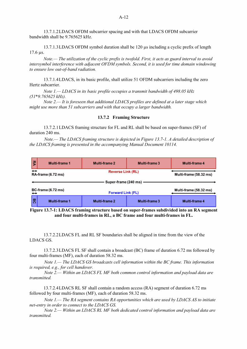
13.7.2.1 LDACS framing structure for FL and RL shall be based on super-frames (SF) of duration 240 ms.
Note.— The LDACS framing structure is depicted in Figure 13.7-1. A detailed description of the LDACS framing is presented in the accompanying Manual Document 10114.
Figure 13.7-1: LDACS framing structure based on super-frames subdivided into an RA segment
and four multi-frames in RL, a BC frame and four multi-frames in FL.
13.7.2.2 LDACS FL and RL SF boundaries shall be aligned in time from the view of the LDACS GS.
13.7.2.3 LDACS FL SF shall contain a broadcast (BC) frame of duration 6.72 ms followed by four multi-frames (MF), each of duration 58.32 ms.
Note 1.— The LDACS GS broadcasts cell information within the BC frame. This information is required, e.g., for cell handover. Note 2.— Within an LDACS FL MF both common control information and payload data are transmitted.
13.7.2.4 LDACS RL SF shall contain a random access (RA) segment of duration 6.72 ms followed by four multi-frames (MF), each of duration 58.32 ms.
Note 1.— The RA segment contains RA opportunities which are used by LDACS AS to initiate net-entry in order to connect to the LDACS GS.
Note 2.— Within an LDACS RL MF both dedicated control information and payload data are transmitted.
A-13
13.7.3 Data Link Services
13.7.3.1 LDACS shall offer acknowledged and unacknowledged bidirectional exchange of user data.
13.7.3.2 LDACS acknowledged data link service shall support acknowledged data transmissions using automatic repeat request (ARQ).
13.7.3.3 LDACS data link service shall offer segmentation and reassembly functions.
Origin: CP
Rationale: The above requirements describe the basic signaling structure of the L-band Digital Aeronautical Communications System including:
a) the basic physical layer characteristics. b) the main elements of the framing structure. c) the data link services supported.
INITIAL PROPOSAL 7
13.8 PERFORMANCE REQUIREMENTS
13.8.1 Mapping to Communications and Surveillance Services
13.8.1.1 LDACS shall support controller-pilot datalink communications (CPDLC) for aeronautical telecommunications network baseline 1 (ATN-B1) services and air-traffic services baseline 2 (ATS-B2).
13.8.1.2 Recommendation.— LDACS should support the future CPDLC air-traffic services baseline 3 (ATS-B3) which are still under development.
Note.— The "should" in Paragraph 13.8.1.2 will become a "shall" as soon as an approved ATS-B3 specification is available.
13.8.1.3 LDACS shall support automatic dependent surveillance - contract (ADS-C).
13.8.2.1 LDACS shall comply with RCP400/A2 and RCP240.
Note.— RCP as defined in ICAO DOC9869 – PBCS Manual, 2nd Edition.
13.8.2.2 LDACS shall comply with RCP130/A1.
Note.— RCP as defined in Eurocae ED228A / RTCA DO-350A – Baseline 2 SPR Standard.
13.8.2.3 Recommendation.— LDACS should comply with the future RCP60.
Note. 1— Draft RCP60 specifications are proposed in SESAR P15.2.4 Future Data Link System Definition – Deliverable D04 QoS and CoS (P15.2.4-D04). Note 2.— The LDACS Manual (Document 10114) will provide further details to map LDACS parameters to the emerging RCP60 requirements.
A-14
Note 3. — The "should" in Paragraph 13.8.2.3 will become a "shall" as soon as an approved RCP60 specification is available.
13.8.3.1 LDACS shall comply with RSP400/A1+A2 and RSP180/D. Note.— RSP as defined in ICAO DOC9869 – PBCS Manual, 2nd Edition.
13.8.3.2 LDACS shall comply with RSP160/A1.
Note.— RSP as defined in Eurocae ED228A / RTCA DO-350A – Baseline 2 SPR Standard.
13.8.3.3 Recommendation.— LDACS should comply with the future RSP60.
Note. 1— Draft RSP60 specifications are proposed in SESAR P15.2.4 Future Data Link System Definition – Deliverable D04 QoS and CoS (P15.2.4-D04).
Note 2.— The LDACS Manual (Document 10114) will provide further details to map LDACS parameters to the emerging RSP60 requirements.
Note 3.— The "should" in Paragraph 13.8.3.3 will become a "shall" as soon as an approved RSP60 specification is available.
13.8.4 Security
13.8.4.1 LDACS shall provide a capability to ensure the availability and continuity of the system.
Note.— The capability includes measures to ensure that the system and its capacity are available for authorized uses during unauthorized events.
13.8.4.2 LDACS shall provide a capability to protect the integrity of messages in transit.
Note.— The capability includes cryptographic mechanisms to provide integrity of messages in transit.
13.8.4.3 LDACS shall provide a capability to ensure the authenticity of messages in transit.
Note.— The capability includes cryptographic mechanisms to provide authenticity of messages in transit.
13.8.4.4 LDACS shall provide a capability for non-repudiation of origin for messages in transit.
13.8.4.5 LDACS shall provide a capability to protect confidentiality/privacy.
Note.— The capability includes cryptographic mechanisms to provide encryption/decryption.
13.8.4.6 LDACS shall provide a mutual authentication capability between the LDACS airborne and the LDACS ground subsystem.
Note.— The capability includes cryptographic mechanisms to provide peer entity authentication, mutual peer entity authentication, and data origin authentication.
13.8.4.7 LDACS shall provide a capability to authorize the permitted actions of users of the system.
Note.— The capability includes mechanisms to explicitly authorize the actions of authenticated users. Actions that are not explicitly authorized are denied.
13.8.4.8 If LDACS provides interfaces to multiple domains, LDACS shall provide capability to prevent the propagation of intrusions within LDACS domains and towards external domains.
13.8.4.9 LDACS services shall be protected against service attacks to a level consistent with the application service requirements.
A-15
Origin: CP
Rationale: The above performance requirements ensure that the L-band Digital Aeronautical Communications System:
a) supports CPDLC and ADS-C in the intended service areas in compliance with ITU regulations.
b) provides the necessary utility to support the intended applications and meet the appropriate RCP/RSP levels.
c) supports all of the above with adequate security.
INITIAL PROPOSAL 8
13.9 SYSTEM INTERFACES
13.9.1 LDACS shall provide a data service interface to the system users.
13.9.2 LDACS shall provide a voice service interface to the system users.
13.9.3 LDACS shall support notification of the status of communications in terms of link quality and supported class of service.
Note.— This requirement shall support notification of the loss of communications (such as join and leave events). Origin: CP
Rationale: The above requirements ensure that the L-band Digital Aeronautical Communications System:
a) provides the necessary system interfaces for voice and data services. b) supports notification of the status of communications including loss of
service notification to the end-users.
INITIAL PROPOSAL 9
13.10 APPLICATION REQUIREMENTS
13.10.1 LDACS shall support multiple classes of service to provide appropriate service levels to applications.
13.10.2 If there is a resource contention, LDACS shall pre-empt services with a lower priority than those given in Annex 10 Vol II, 5.1.8.
A-16
Origin: CP
Rationale: The above requirements ensure that the L-band Digital Aeronautical Communications System:
a) supports quality of service (QoS). b) supports pre-emption of low priority services.