1. INTRODUCTION Tripura Forest Development and Plantation Corporation Limited is a Public Sector Undertaking of Government of Tripura. The Corporation is working for re-vegetation of degraded forestland through Rubber plantation and other forest resources to ensure development and upliftment of economically weaker sections of the society. The Corporation was registered under the Companies Act, 1956 on 26-03-1976. The main objective of the Corporation is to carry out business in plantation crops with special emphasis on Rubber plantations. Besides business activities the Corporation also takes up social responsibility for poverty alleviation through Rubber plantation for Schedule Cast, Schedule Tribe, Other Backward Caste and other rural poor families. TFDPC Industrial Estate, Anandanagar, situated 12 km away from Agartala city is one of the Division of Tripura Forest Development & Plantation Corporation Ltd having following activities
1. Processing and Treatment of Rubber Wood 2. Production of Solid Rubber Wood Board 3. Manufacturing of Rubber Wood Furniture including interior decoration 4. Manufacturing of Doors, Windows, Kitchen Shutters etc. 5. Processing & Value Addition of Bamboo including manufacturing Bamboo
furniture and decorative items. 1.1 MISSION Our mission is to furnish modern houses with natural wood products through ensuring sustainable livelihoods to the plantations communities. 1.2 VISION STATEMENT We envision converting sustainably harvested wood into quality modern furnishing products while ensuring enhanced incomes of the planters.
2. OBJECTIVES In order to realize its vision TFDPCL Industrial Estate, Anand nagar has set following long-term and short term objectives for itself: 2.1 LONG TERM OBJECTIVES
a. Setting standards of manufacturing modern quality wood furnishing products b. Setting standards of performance of wood processing, value addition,
manufacturing, branding & marketing of wood furnishing products c. Setting benchmarks in being environmentally and socially responsible business
TFDPCL MGMT PLAN – III IEA Management Manual 203
2.2 SHORT TERM OBJECTIVES
a. Establishing operational capabilities to design and manufacture of Rubber Wood Board, Rubber Wood Furniture (Doors, Windows, Kitchen shutters) & Bamboo products to cater to the needs of the modern houses
b. Establishing modern facilities for Processing and Treatment of Rubber Wood and Bamboo
c. Establishing centre for wood product design and development d. Developing human resource capabilities through setting high standards of working
environment, health, and safety e. Establishing waste management facilities to ensure good quality of life for both
internal and external communities / people f. Set up IT enabled MIS for smooth, accurate and timely flow of information within
the unit and with other units 2.3 TARGETS
For achieving its above stated objectives the following specific targets are set for achievement during the next two years and five years respectively.
2.3.1 To achieve following long-term production targets (within next Five years)
To achieve following short-term production targets (within next two years)
a. Production of Treated Rubber Wood – 24000 CFT per annum b. Production of Rubber Wood Boards – 12,000 nos per annum c. Production of Furniture – 12,000 units per annum d. Production of Doors – 12,000 nos per annum e. Production of Bamboo Furniture – 1,500 units per annum f. Achieve standards of working environment, health, and safety at par with industry
norms and legal compliance g. Recruitment, training and development of human resource as per currently
sanctioned staff strength h. Arrange training of all existing staff in their field of specialization and also for
their health and safety i. Set up HR policy which is incentive based and that promotes healthy competition
among achievers and deters non-performance j. Set up IT enabled Database Management System with computer spreadsheets
for all types of records and internet based data access and transfer mechanism 2.3.2 To achieve following long-term production targets (within next Five years)
a. Production of Treated Rubber Wood – 24000 CFT per annum b. Production of Rubber Wood Boards – 12,000 nos per annum c. Production of Furniture – 12,000 units per annum d. Production of Doors – 12,000 nos per annum e. Production of Bamboo Furniture – 1,500 units per annum f. Review the HR Needs for five years to commensurate with production targets.
TFDPCL MGMT PLAN – III IEA Management Manual 204
3. ASSETS 3.1 Land
TFDPC Industrial Estate is situated 12 km away from Agartala city. The details of land available with the unit is given below
Mouja :- Anandanagar No 25 Sheet No :- 5 Tahsil :- Srinagar Revenue Circle :- Takarjola Sub-Division :- Bishalgarh Dist. :- West Tripura
Land Status
Khash Land :- 7.855 Ha Jute Land:- 2.504 Ha Total Land :- 10.357 Ha
3.2 Building & construction The following physical assets are installed in the Industrial Estate
a. Administrative Office Building including Guest House b. Diosgenin factory Building including workshop c. Central Godown 1,2,& 3 d. Bamboo Development Unit e. Central Store room f. Timber Treatment Plant g. Unakoti crafts & furniture Unit including show room h. Tripura Rubber wood factory i. Process cum Product Development unit j. Door Manufacturing Unit k. Bamboo Dormitory l. Carpenters barrack m. Water supply system including over head water tank & pipeline
4. ACTIVITIES TFDPC Industrial Estate undertakes following activities Processing and Treatment of Rubber Wood in Timber Treatment Plant.
Production of Solid Rubber Wood Board in Tripura Rubber Wood factory
Manufacturing of Rubber Wood Furniture including interior decoration in Unakoti Crafts & Furniture Unit
Manufacturing of Doors, Windows, Kitchen Shutters etc in Door Manufacturing Unit.
Processing & Value Addition of Bamboo including manufacturing Bamboo furniture and decorative items.
TFDPCL MGMT PLAN – III IEA Management Manual 205
4.1 TIMBER TREATMENT PLANT After attaining economically viable maturity i.e. Productive Line of about 24 years starting from 7th years upto 31 years of Age Rubber trees need to be felled and timber used for various end uses as described earlier. Thus the land available is to be replanted. Similarly Gaps created due to damage of plantations caused by Natural calamities e.g. cyclones, Hurricanes, Drought, Frost , Soil & Wind erosion and other Biotic factors are to be covered by Replenishment plantings in order to optimize the productivity from Rubber Plantations. The availability of the traditional timber which are naturally durable & resistant to degradation like Sal, Teak, Rose etc are dwindling leading to emergence of other timber such as rubber wood (Hevea brasilensis ) as one of the alternatives for the traditional sources of timber in the world market. The most distinctive feature of rubber wood is that it is a renewable by product of Rubber plantation, thus commercial exploitation of Rubber wood assumes added significance as it contributes to the environmental conservation. It is easily treatable and supply of rubber wood is inexhaustible in Tripura as the rubber plantation is maintained here on sustained basis. The Corporation established this TIMBER TREATMENT PLANT with the financial assistance of Indian Council for Forest Research & Education (ICFRE), Dehradum. The plant was commissioned in June 1999 having processing capacity of 1000 cum of round timber per annum. In the year 2005-06 the capacity of the industrial unit was increased from 1000 cu to 2400 cum per annum after introducing trolley saw machine and hot water circulated 1000 CFT capacity timber seasoning kiln. Presently the acceptability of the treated Rubber timber is established in the market. 4.1.1 THE TIMBER TREATMENT PROCESS
The process flow chart of TIMBER TREATMENT PLANT is Rubber Logs Horizontal band Saw
Vertical band Saw mill
Treatment Chemicals
Treatment Vessels
(Boric Acid & Borax)
Hot Water Generators Hot Water
Seasoning Kilns
Re-Saw Band Saw Machine
Final Product to Unakoti Crafts & Furniture Unit, Door Manufacturing Unit, Bamboo Development Unit and Direct sale.
TFDPCL MGMT PLAN – III IEA Management Manual 206
4.1.2 TIMBER TREATMENT PROCESS DESCRIPTION 4.1.2.1 LOG RECEIPT Rubber Logs are received after confirmation with the tree felling schedule and checking the following specifications
a. Length of log between 1m to 4m b. Centre Girth of log not below 60cm c. Tapping marks not more than 10% d. No knots & branches e. Time of felling not more than 36 hrs.
Logs passing through the above quality parameters are measured and received, Stock entry of each log including volume as calculated is made in LOG RECEIPT REGISTER on daily basis. Log received are issued by Raw Material Store Keeper to shop floor supervisor for Sawing. 4.1.2.2 SAWING Sawing of logs are done in two stages. Initially logs are sawn in HORIZONTAL BAND SAW machine to plunks of thickness 62 mm ( 2.5 inches) to 100mm (4 inches) depending upon the indent and log quality & size. The plunks so produces are converted to required size in VERTICAL BAND SAW machine. Conversion at this stage is 30% to 35% depending on size of Timber swan. Volume of converted timber is recorded in LOG CONVERSION REGISTER on daily basis by Raw Material Store Keeper. 4.1.2.3 CHEMICAL TREATMENT Swan timber is treated with chemicals of definite mix and definite concentration under specific pressure and time. {Presently 1.5% Boric Acid, 2.25% Borax and 0.15% Sodium Pentachlorophenate chemical solution is used for treatment). Sawn timber is feed in TREATMENT VESSEL, closed air tight, 400 mmHg of vacuum is created and kept for 10 minutes to take out excess air from the vessel. Thereafter, the vessel is filled with chemical solution so prepared and subjected to a stable pressure of 8 kg per mm2 for 2 ½ hours. Batch No is provide for each treatment quantum of timber. Periodic re-filling of chemicals to maintain concentration is done and laboratory test of each batch is done to confirm required chemicals absorption. 4.1.2.4 SEASONING The next process is seasoning of swan timber. The treated swan timber is staked in the SEASONING KILNS in definite method and hot air at controlled temperature depending upon the humidity is allowed to pass for seasoning of swan timber. 4.1.2.5 RE-SAWING & DISPATCH The seasoned timbers are re-sawn in RE-SAW BAND SAW MACHINE if required. The product ROUGH SWAN KILN DRIED TIMBER is ready for sale and further use in other units of the Industrial Estate for further value addition. TFDPCL MGMT PLAN – III IEA Management Manual 207
4.1.3 TIMBER TREATMENT MACHINE DETAILS 4.1.3.1 HORIZONTAL BAND SAW
a. Quantity :- 1 no. b. Specification :- Wheel diameter – 42 inches, Saw motor 20hp, suitable for saw
blade size 3 inches with necessary saw guard, lubricating system & protection gears etc with accessories
4.1.3.2 VARTICAL BAND SAW
a. Quantity :- 1 no. b. Specification :- Wheel diameter – 36 inches, Saw motor 10hp, suitable for saw
blade size 2.5 inches with necessary saw guard, lubricating system & protection gears etc with accessories
4.1.3.3 Components of Vacuum Pressure Impregnation Plant size 4ft 6
inches dia x 20 ft long. a. Quantity :- 2 no. b. Specification :-
i. Impregnation Vessel Size:- Dia 3ft 6 inches x 18 ft long ii. Treatment Capacity :- 100 Cft/Charge iii. Impregnation Vessel – Horizontal cylindrical welded steel construction type
fitted with wedge lock design quick opening door on one end. Other end blanked off with formed dished end cover. Material of construction of shell shall be carbon steel to IS:2062 of 16 mm thickness and dish 20 mm thick. All other steel materials shall be IS:2062. Door opening shall be by manual lever- gear arrangements. The vessel shall be capable of withstanding vacuum of 650mm Hg and pressure of 16kg/cm2.
iv. Vacuum pump set:- Vacuum pump shall be water ring type having suction capacity of approximately 170m3/hr. Pump is equipped with TEFC, squirrel cage induction motor of 5.625 KW. Pump operation shall be at 1450 RPM.
v. Pressure Pump:- Pressure pump shall be horizontal, high pressure triplex pump, 2000 LPH, generating a head of 300 psi pressure fitted with 2.25 KW, 1440 rpm squirrel cage TEFC induction pump.
vi. Valves :- All Valve in service shall be plug valve and tested to 250 psi. vii. Pipelines :- All pipelines shall be ERW construction to IS-1239(M) grade. viii. Control board :- control board with DOL Starter and main switch to be
provided. ix. Internal & external tracks and trolley for loading 100 CFT timber. x. Drawings and Manuals for construction of storage cum mixing tank.
4.1.3.4 Components of 500 CFT capacity overhead type timber
seasoning kiln capable of drying of timber upto uniform moisture content of 8% with a variation of ±2%.
2. Seasoning Capacity:-500 CFT per charge in each chamber using 1 inch
planks and 1 inches crossers. 3. Components :- i. Axial fan units (Multi bladed – fans are made of Cast Aluminum to prevent
corrosion) fitted with motor ( Fan motors are with Class „H‟ insulation for continuous running in the Kiln at scheduled temperature of seasoning) & mounted on sub ceiling ( false ceiling) – 2 nos.
ii. Top mounted aluminum finned heat exchangers, tested hydraulically at 5 kg/cm2 pressure or double of working pressure, whichever in more. – 4 nos.
iii. Exhaust unit (chimney ) with opening and closing self acting flap.- 1 no. iv. Fresh air units with ducts opening & closing device - 2 nos. v. Internal construction for kiln with bracket, fan housing, baffles etc. – 1 set. vi. M.S. structure and sheet materials for false ceiling – 1 set vii. Charging door & inspection door with locking arrangements & hinges – 1 no viii. Humidifying device – 1 set ix. Internal & external pipeline with control valves ( MS pipes confirming to
IS:1239) – 1 set. x. Electrical control board – 1 no
4.1.3.5 Components of 1,00,000 K.Cal / Hour capacity Hot Water Generator
a. Quantity :- 1 no. b. Specification :-
1. Capacity :- 1,00,000 K.Cal Each 2. Fuel :- Wood chips and Saw dust 3. Temperature :- 80 oC 4. Hot Water Generating Tank :- 1 no 5. Fire Box :- 1 no 6. Chimney with guy rope & turn buckles:- 1 no 7. Expansion tank with legs :- 1 no 8. Hot water circulation pump :- 1 no 9. Pipeline :- 1 set 10. Thermometer :- 1 no 11. Necessary insulation materials:- 1 lot 12. Fire bricks :- 1 lot
4.1.3.6 RE-SAW BAND SAW
a. Quantity :- 1 no. b. Specification :- Wheel diameter – 30 inches, Saw motor 7.5hp, suitable for
saw blade size 2 inches with necessary saw guard, lubricating system & protection gears etc with accessories
4.1.4 Maintenance schedule, safety measures and minimum inventory
requirement timber treatment machines 4.1.4.1 HORIZONTAL BAND SAW TFDPCL MGMT PLAN – III IEA Management Manual 209
a. Maintenance Schedule
Daily (after 16 hours operation) :- Check and adjust the tension of blade and the electrical control system
and mechanical system to see if any part is in safety state. Oiling every part Test run the machine in idle condition to inspect its function. Through cleaning of saw dust from every corner of machine especially
in the electric control equipment. Weekly (after 96 hours operation) :-
Tighten all nuts and bolts. Check gear box and other drive system. Tighten all screw and connection of electrical control system.
b. Safety measures
Saw blade safety guard is attached to the machine. Emergency stop switch is located near the operator and other easy reach
positions. All the electrical connections are through safety gears and regulators. Workers are provided with uniform, industrial shoes, helmet, eye
protection goggles and musk. Workers are properly trained by the supplier of the machine.
c. Inventory schedule
Saw Blade – 19 gauge 62mm ( 2 ½ inches) saw blade -500 RFT Bearings – 32212 - 4 nos Bearings - 32211 - 4 nos
4.1.4.2 VARTICAL BAND SAW
a. Maintenance Schedule Daily (after 16 hours operation):-
Check and adjust the tension of blade and the electrical control system and mechanical system to see if any part is in safety state.
Oiling every part Test run the machine in idle condition to inspect its function. Through cleaning of saw dust from every corner of machine especially
in the electric control equipment. Weekly (after 96 hours operation) :-
Tighten all nuts and bolts. Check gear box and other drive system. Tighten all screw and connection of electrical control system.
b. Safety measures
Saw blade safety guard is attached to the machine. Emergency stop switch is located near the operator and other easy reach
positions. All the electrical connections are through safety gears and regulators.
TFDPCL MGMT PLAN – III IEA Management Manual 210
Workers are provided with uniform, industrial shoes, helmet, eye protection
goggles and musk. Workers are properly trained by the supplier of the
machine c. Inventory schedule Saw Blade – 19 gauge 62mm ( 2 ½ inches) saw blade -500 RFT Bearings –6212 - 4 nos Bearings- 6213 - 4 nos
4.1.4.3 Components of Vacuum Pressure Impregnation Plant size 4ft 6
inches dia x 20 ft long.
a. Maintenance Schedule Daily (after 16 hours operation):-
Check the safety valve, main door gasket and the electrical control system and mechanical system to see if any part is in safety state.
Oiling every part Test run the machine in idle condition to inspect its function. Through cleaning of saw dust from every corner of machine especially
in the electric control equipment. Weekly (after 96 hours operation) :-
Tighten all nuts and bolts. Check gear box and other drive system. Tighten all screw and connection of electrical control system.
b. Safety measures
Pressure safety valve is attached to the machine. Emergency stop switch is located near the operator All the electrical connections are through safety gears and regulators. Workers are provided with uniform, industrial shoes, helmet, eye protection
goggles and musk. Hand gloves are provided for mixing of chemicals. Workers are properly trained by the supplier of the machine
c. Inventory schedule
i. Spare for pressure pump
a. Valve assembly 6 no b. V packing ring set 4 nos c. Seal Ring 4 nos d. Bimetallic bearing 4 nos e. Oil seal for crank shaft 4 nos f. Bush 4 nos g. Dowel Pin 4 nos h. Oil sea for piston rod 4 nos
ii. Spares for Vacuum Pump a. Gland packing set (front & Rear) 2 nos b. Gasket 2 nos
TFDPCL MGMT PLAN – III IEA Management Manual 211
c. Coupling 1 no d. Rubber Spider for coupling 4 nos iii. Door Rubber Gasket 2 no iv. Safety Valve 2 nos
4.1.4.4 Components of 500 CFT capacity overhead type timber
seasoning kiln capable of drying of timber upto uniform moisture content of 8% with a variation of ±2%.
a. Maintenance Schedule
Daily (after 16 hours operation):- Check water level in the overhead tank Check for any leakage in the water and hot water pipe line. Fill water in wet bulb temperature gauge tray.
Weekly (after 96 hours operation):-
Tighten all nuts and bolts. Check circulating fan motor and other electrical connections. . Tighten all screw and connection of electrical control system.
b. Safety measures
All the electrical connections are through safety gears and regulators. Workers are provided with uniform and industrial shoes, Workers are properly trained by the supplier of the machine
c. Inventory schedule
i. Spare for circulating pump a. Flap valve 2 nos b. Impeller 2 nos c. Coupling 2 nos d. Rubber Spider for coupling 4 nos
ii. Temperature Gauge for seasoning kilns 2 no iii. 1” Angular safety valve 1 no iv. ½” Straight safety valve 1 no v. Compound Gauge 2 nos
4.1.4.5 Components of 1,00,000 K.Cal / Hour capacity Hot Water Generator
a. Maintenance Schedule Daily (after 16 hours operation):-
Check water level in the overhead tank Check for any leakage in the water and hot water pipe line.
Weekly (after 96 hours operation):- Tighten all nuts and bolts.
TFDPCL MGMT PLAN – III IEA Management Manual 212
Monthly
Clean fire pipe and fire oven thoroughly
b. Safety measures All the electrical connections are through safety gears and regulators. Workers are provided with uniform and industrial shoes Workers are properly trained by the supplier of the machine
c. Inventory schedule
i. Hot water circulating pump – 1 no ii. Spares for circulation pump
a. Mechanical seal - 4 no b. Oil seal - 4 nos c. Shaft - 2 no
4.1.4.6 RE-SAW BAND SAW
a. Maintenance Schedule Daily (after 16 hours operation):-
Check and adjust the tension of blade and the electrical control system and mechanical system to see if any part is in safety state.
Oiling every part Test run the machine in idle condition to inspect its function. Through cleaning of saw dust from every corner of machine especially
in the electric control equipment. Weekly (after 96 hours operation):-
Tighten all nuts and bolts. Check gear box and other drive system. Tighten all screw and connection of electrical control system.
b. Safety measures
Saw blade safety guard is attached to the machine. Emergency stop switch is located near the operator. All the electrical connections are through safety gears and regulators. Workers are provided with uniform, industrial shoes, helmet, eye protection
goggles and musk. Workers are properly trained by the supplier of the machine
4.2 Tripura Rubber Wood Factory World Timber Trade is gaining high tech and Solid Wood Boards are in high demand in the world. In order to keep pace with modern technology and also to tap the available market, TFDPC has set up TRWF with an investment of Rs 8 crores. The total capacity of the factory is 40 solid wood boards with finger jointing technique. Presently the solid rubber wood boards produced is being used in the Unakoti crafts & furniture Unit and in the Door Manufacturing Unit situated within the Industrial Estate. TFDPCL MGMT PLAN – III IEA Management Manual 214
Dust line Dust Collector 1
Multiple Rip Saw with planer 1
Multiple Rip Saw with planer 2
Jump Saw 1 Jump Saw 2
Treatment Chemicals (Boric Acid & Borax)
2 nos Hot Water Generators
Treatment Vessel Hot Water 10 nos Seasoning Kilns D us
t Li ne
Jump Saw 3 Jump Saw 4
Glue
Five head four side planer
Finger Joint Machine Six head four side planer
Air Compressor
Dust Collector 2
Glue Spreader
Panel Saw
Composer Wide belt Sender
Final Product for packing
Beam Saw
TFDPCL MGMT PLAN – III IEA Management Manual 215
4.2.1 The Solid Wood Board Making Process The process flow chart of Tripura Rubber Wood Factory Rubber Logs
Log band Saw mill with log carriage
Vertical band Saw mill
4.2.2 The Solid Wood Board Process Description 4.2.2.1 LOG RECEIPT Rubber Logs are received after confirmation with the tree felling schedule and checking the following specification
f. Length of log between 1m to 4m g. Centre Girth of log not below 60cm h. Tapping marks not more than 10% i. No knots & branches j. Time of felling not more than 36 hrs.
Logs passing through the above quality parameters are measured and received, Stock entry of each log including volume as calculated is made in LOG RECEIPT REGISTER on daily basis. Log received are issued by Raw Material Store Keeper to shop floor supervisor for Sawing. 4.2.2.2 SAWING Sawing of logs are done in two stages. Initially logs are sawn in VERTICAL BAND SAW WITH LOG CARRIAGE machine to plunks of thickness 80 mm. The plunks so produces are converted to required size in VERTICAL BAND SAW machine. Conversion at this stage is 30% to 35%. The plunks are the ripped to different width as per demand of final product dimension. Ripped timber is than cut in Jump Saw machine to reject tapping marks, knots and other defect. Volume of converted timber is recorded in LOG CONVERSION REGISTER on daily basis by Raw Material Store Keeper. 4.2.2.3 CHEMICAL TREATMENT Swan timber is treated with chemicals of definite mix and definite concentration under specific pressure and time. {Presently 1.5% Boric Acid, 2.25% Borax and 0.15% Sodium Pentachlorophenate chemical solution is used for treatment). Sawn timber is feed in TREATMENT VESSEL, closed air tight, 400 mmHg of vacuum is created and kept for 10 minutes to take out excess air from the vessel. Thereafter, the vessel is filled with chemical solution so prepared and subjected to a stable pressure of 8 kg per mm2 for 2 ½ hours. Batch No is provide for each treatment quantum of timber. Periodic re-filling of chemicals to maintain concentration is done and laboratory test of each batch is done to confirm required chemicals absorption. 4.2.2.4 SEASONING The next process is seasoning of swan timber. The treated swan timber is staked in the SEASONING KILNS in definite method and hot air at controlled temperature depending upon the humidity is allowed to pass for seasoning of swan timber. Hot air is generated by heat exchange between hot water and air inside the kiln. Hot water is generated in Hot Water generator using waste timber. TFDPCL MGMT PLAN – III IEA Management Manual 216
4.2.2.5 Planning & Sorting Seasoned timber is than cut in Jump saw machine, if required, to reject any defective part. Then the timber is passed through four side planing machine, at times twice, and that sorted manually to different grades. 4.2.2.6 Finger Jointing Seasoned, planed & graded timber is processed in finger joint line for production of finger jointed lamina. In Finger Jointing machine fingers of 4mm pitch and 16mm depth if done on both side of timber. Glue is applied automatically and then pressed to form lamina of 8ft (1200 mm) length. The lamina so produced in the finger joint machine is composed in composer to produce 8ft x 4ft boards of thickness 12mm, 15mm, 18mm, 22mm, 25mm, 30mm and 35mm. The final product, 4.2.2.7 Composing The lamina so produced in the finger joint machine is again planned in six head moulder. The planned lamina is then passed though glue applicator to spread a thin layer of glue and then composed in composer to produce 8ft x 4ft boards of thickness 12mm, 15mm, 18mm, 22mm, 25mm, 30mm and 35mm. 4.2.2.8 Trimming & finishing Finger jointed solid wood boards are then passed though beam saw for trimming and wide belt sander for sanding and then ready for further use in carpentry unit or sale. 4.2.3 Utility service & Ancillary works The utility service and ancillary works related to boards production are 4.2.3.1 Saw blade preparation Saw blades for both the vertical band saw machines are received in the form of steel trip with required size & shape teething. In the workshop, steel trip are cut into desired length and then joint to form circular loop. Teeth of the blade is sharpen in grinding machine before us and also periodically while the blades are in use. 4.2.3.2 Sharpening of tools Tools like circular saw blades, finger joint cutter, Planer blades, trimming blades etc are generally procured from outside Tripura. Periodic sharpening and maintenance of tools are done in the workshop. 4.2.3.3 Dust Collection While sawing, cutting, trimming, planning and sanding of timber or board a lot of saw dust is produced. To have a dust free environment for workers the factory has three dust colleting systems. TFDPCL MGMT PLAN – III IEA Management Manual 217
a. Centralized wet dust collecting system for saw dust produced at Sawing section
before seasoning of timber. All the machines of sawing section are connected by pipe and dust is sucked by a centrifugal pump and dust is collected in the dust collecting chamber which is sold.
b. Centralized wet dust collecting system for dry dust produced at main process hall. All the machines of process hall except wide belt sander are connected by pipe and dust is sucked by a centrifugal pump followed by cyclone separator and dust is collected in the dust collecting chamber which is sold.
c. Individual dust collecting machine for wide bent sander collects fine dust produced at wide bet sander, collected in dust collecting bag and sold outside.
4.2.3.4 Compressed air supply Most of the machines in the Tripura Rubber Wood Factory are pneumatically operated and for this purpose compressed air is supplied though centralized air compressor and network of pipeline. 4.2.3.5 Power supply Main source of power for this factory is from Tripura State Electric Corporation Limited. One 500 KVA transformer is installed for this purpose. One 250 KVA Generator is alternative source of power for this factory. Sophisticated and high safety electric control panel ensures proper electrification of the machine. All machines are properly earthen and the factory is installed with lightening arresters at different locations. 4.2.3.6 Water supply Water supply system having two nos deep tube well, Aeration Tank, Iron Removal Plant, Overhead Water tank, network of pipeline are source of required water for the plant. 4.2.3.7 Firefighting equipments Adequate fire extinguishers are installed and checked periodically to avoid any fire hazard. 4.2.3.8 Material Handling equipment Two nos of forklift trucks and few pallet lifters make the movement of material easy for the operation in this factory. 4.2.4 The Solid Wood Board Making Machine Details 4.2.4.1 Log Band Saw with log carriage.
a. Quantity :- 1 no. b. Specification :- Wheel diameter – 42 inches, with log carriage (14 ft long), rail
length for log carriage 45 ft with 4 clamping devices and hand liver & clatch drive for driving the log carriage on rack & pinion drive. Saw motor
TFDPCL MGMT PLAN – III IEA Management Manual 218
25 hp, log carriage motor – 5hp, suitable for saw blade size 4 inches with necessary saw guard, lubricating system & protection gears etc.
4.2.4.2 Vertical Band Saw Machine with auto feeder
a. Quantity :- 1 no. b. Specification :- Wheel diameter – 42 inches, Saw motor 15hp, suitable for saw
blade size 3 inches with necessary saw guard, Auto feeder (Centeuro RA210/P Pneumatic Feeder), lubricating system & protection gears etc with accessories
4.2.4.3 Double Side Planner with Multi Rip Saw.
a. Quantity :- 3 no. b. Specification :- Saw Blade Dia – 300mm , Max Working Width 200mm,
Maximum Working Thickness – 75mm, heavy duty rigid steel construction, moving shaft with heavy bearing, Motor Power – 7.5 hp, 5.5 hp, 30 hp, 0.5 hp, 3 hp, 0.5 hp (46 hp).
4.2.4.4 Jump Saw
a. Quantity :- 4 no. b. Specification :- Motor hp – 5 hp, blade diameter – 450 mm, teeth – 108 nos,
pneumatically jumping blade on foot peddle control, conveyors for timber – 2 mtrs on feeding end & 1 mtr on other end with necessary saw guard, lubricating system & protection guards.
4.2.4.5 Vacuum Pressure Impregnation Plant size 4ft 6 inches dia x 20
ft long. a. Quantity :- 1 no. b. Specification :-
i. Impregnation Vessel Size:- Dia 4ft 6 inches x 20 ft long ii. Treatment Capacity :- 150 Cft/Charge iii. Impregnation Vessel – Horizontal cylindrical welded steel construction type
fitted with wedge lock design quick opening door on one end. Other end blanked off with formed dished end cover. Material of construction of shell shall be carbon steel to IS:2062 of 16 mm thickness and dish 20 mm thick. All other steel materials shall be IS:2062. Door opening shall be by manual lever- gear arrangements. The vessel shall be capable of withstanding vacuum of 650mm Hg and pressure of 16kg/cm2.
iv. Vacuum pump set:- Vacuum pump shall be water ring type having suction capacity of approximately 170m3/hr. Pump is equipped with TEFC, squirrel cage induction motor of 5.625 KW. Pump operation shall be at 1450 RPM.
v. Pressure Pump:- Pressure pump shall be horizontal, high pressure triplex pump, 2000 LPH, generating a head of 300 psi pressure fitted with 2.25 KW, 1440 rpm squirrel cage TEFC induction pump.
vi. Valves: - All Valves in service shall be plug valve and tested to 250 psi. vii. Pipelines: - All pipelines shall be ERW construction to IS-1239(M) grade.
TFDPCL MGMT PLAN – III IEA Management Manual 219
viii. Control board: - control board with DOL Starter and main switch to be
provided. ix. Internal & external tracks and trolley for loading 150 CFT timber. x. Drawings and Manuals for construction of storage cum mixing tank.
4.2.4.6 Components of 500 CFT capacity overhead type timber
seasoning kiln capable of drying of timber upto uniform moisture content of 8% with a variation of ±2%.
2. Seasoning Capacity:-500 CFT per charge in each chamber using 1 inch planks and 1 inch crossers.
3. Components :- i. Axial fan units (Multi bladed – fans are made of Cast Aluminum to
prevent corrosion) fitted with motor (Fan motors are with Class „H‟ insulation for continuous running in the Kiln at scheduled temperature of seasoning) & mounted on sub ceiling ( false ceiling) – 2 nos.
ii. Top mounted aluminum finned heat exchangers, tested hydraulically at 5 kg/cm2 pressure or double of working pressure, whichever in more. – 4 nos.
iii. Exhaust unit (chimney) with opening and closing self acting flap.- 1 no.
iv. Fresh air units with ducts opening & closing device - 2 nos. v. Internal construction for kiln with bracket, fan housing, baffles etc. – 1
set. vi. M.S. structure and sheet materials for false ceiling – 1 set vii. Charging door & inspection door with locking arrangements & hinges
– 1 no viii. Humidifying device – 1 set ix. Internal & external pipeline with control valves (MS pipes confirming
to IS: 1239) – 1 set. x. Electrical control board – 1 no
4.2.4.7 Components of 5,00,000 K.Cal / Hour capacity Hot Water
Generator a. Quantity :- 2 no. b. Specification :- i. Capacity :- 5,00,000 K.Cal Each ii. Fuel :- Wood chips and Saw dust iii. Temperature :- 80 oC iv. Hot Water Generating Tank :- 1 no v. Fire Box :- 1 no vi. Chimney with guy rope & turn buckles:- 1 no vii. Expansion tank with legs :- 1 no viii.Hot water circulation pump :- 1 no
TFDPCL MGMT PLAN – III IEA Management Manual 220
ix. Pipeline :- 1 set x. Thermometer :- 1 no xi. Necessary insulation materials:- 1 lot xii. Fire bricks :- 1 lot
4.2.4.8 Four Side Planner ( five head)
a. Quantity :- 1 no. b. Specification :- Five head moulder – two no top planner, 1 bottom planner & 2
on each side.
i. Should be capable of planning minimum length of timber 200mm and minimum width of timber 25mm and minimum thickness 6mm.
ii. Feed speed variable from 5m/min to 25m/min. iii. Maximum width of feed – 180 mm iv. Maximum thickness of feed – 130mm v. Motor hp-10Hp for each head. vi. Pneumatic up down movement for thickness adjustment vii. Cutting circle for the cutter–125 to 180 mm viii. Cutting head of four blade type ix. Spare parts – with two horizontal and two vertical cutter block for spindle, 4
pneumatic cylinders, 4 universal joints, 1 set blades setting device and appropriate tools like spanners, Allen Keys, Screw Driver, Grease Gum and Oil Can.
4.2.4.9 Finger Joint Machine
a. Quantity :- 1 no b. Specification 1. Finger shaper:-
i. With cut off saw, automatic gluing attachment & brushing attachment ii. The feed table 600mm width & 800 mm long with necessary suction
goods. iii. Shaper motor – 15 to 20 Hp. iv. Necessary pitch adjustment on the second side. v. Shaping cycle speed 30 to 40 sec.
vi. Spares - 4 sets of finger cutter, glue combs, 4 nos of cutoff saw, brushes, one set pneumatic valves & cylinders with other standard spares.
2. Hydraulic Finger assembler i. Total length – 6 m with provision for intermediate length cutting,
double push seat operation. ii. Minimum thickness - 12mm iii. Minimum width - 30 mm iv. Maximum thickness - 75 mm v. Maximum width - 150 mm
vi. Hydraulically operated vii. Spares - hydraulic valves & cylinders. viii. Motors – 5 to 7.5 Hp for hydraulic pump,3 Hp for cutter saw
TFDPCL MGMT PLAN – III IEA Management Manual 221
4.2.4.10 Composer
a. Quantity :- 1 no. b. Specification :- Hydraulically operated upward opening surface press cover
type rotary composer. i Working station :- 4 (four) ii Working Length :- 5200mm iii Working width :- 1300mm iv Working thickness:- 150 mm. v Automatic selector and special detaching cycle after pressuring and Double
micro contact pressure gauge to set working pressure for each hydraulic unit.. 4.2.4.11 Glue Spreader
a. Quantity :- 1 no.
b. Specification :- i Roller type glue spreader with chain driven conveyor table. ii Two side gluing mechanism. iii Width of the roller :- 610mm iv Length of the table:- min. 3000 mm v Glue spreading capacity should be controlled on 250 to 300 gm per sqm.
4.2.4.12 Panel Saw
a. Quantity :- 1 no. b. Specification :- Panel saw with sliding attachment
i. Length of Sliding table – min. 3200 mm ii. Diameter of Saw blade – min. 300 mm iii. Depth of cut - 90 mm iv. Cutting tolerance - 2 mm v. Saw tilt - 45 degree vi. Speed of Saw Blade- 2800 RPM to 5600 RPM vii. Main Motor Hp – 5 Hp viii. Diameter of Scoring Saw- 120 mm ix. Speed of Scoring Saw - 8500 RPM x. Scoring Motor Power - 1 Hp xi. Dust collector of appropriated design. xii. Mechanism should be provided to raise, lower the saw blades and canted upto
45 deg. xiii. Sliding mechanism should be provided with linear guide rollers
4.2.4.13 Four Side Planner ( Six head )
a. Quantity :- 1 no. b. Specification :- Six head moulder – two no top spindles, two bottom spindles
& two side spindle. i. Feed speed variable from 6m/min to 30m/min. ii. Maximum width of feed – 230 mm iii. Maximum thickness of feed – 120mm
TFDPCL MGMT PLAN – III IEA Management Manual 222
iv. Motor hp-10Hp each for three spindle heads, 15hp each for three spindle
heads and 5.5 hp feed motor. 4.2.4.14 Auto Wide Belt Planer Sander
a. Quantity :- 1 no. b. Specification :-
i. Working width – 1300 mm,Working thickness – 125 mm. ii. Feed speed – 4-16 m/mim iii. Main Motor 40,30,20hp,Feed motor 7.5 Hp, Table hoist motor 1 hp
v. Micro computer for high accuracy and thickness setting, vi. Anti kickback fingers vii. Auto brake viii. Safety guards ix. Spiral cutter head
4.2.5 Maintenance Schedule, Safety schedule & Minimum Inventory for
Solid Wood Board Making Machines 4.2.5.1 Log Band Saw with log carriage.
a. Maintenance Schedule Daily (after 16 hours operation):-
Check and adjust the tension of blade and the electrical control system and mechanical system to see if any part is in safety state.
Oiling every part Test run the machine in idle condition to inspect its function. Through cleaning of saw dust from every corner of machine especially
in the electric control equipment. Weekly (after 96 hours operation) :-
Tighten all nuts and bolts. Check gear box and other drive system. Tighten all screw and connection of electrical control system.
b. Safety measures
Saw blade safety guard is attached to the machine. Emergency stop switch is located near the operator and other easy reach
positions. All the electrical connections are through safety gears and regulators. Workers are provided with uniform, industrial shoes, helmet, eye protection
goggles and musk. Workers are properly trained by the supplier of the machine.
c. Inventory schedule
i. Trolley motor chain size 16mm double chain with chain lock – 1 set of 4 pices
ii. Limit switch for saw guide People make -1EC-947-5-1 1 no iii. Top end of lead-screw for up and down support 1 no iv. Voltage regulator transformer for panel board. 1 no
TFDPCL MGMT PLAN – III IEA Management Manual 223
v. Roll Bearing 4 nos each
a. 3611 (55x120xc43) b. 8205 (25x47x15 d1=25.2) c. 38025(25x47x28 d1=25.2, d2=20) d. 3612 (60x130x46) e. 3615 (75x160x55) f. 8107 (35x52x12 d1=35.2) g. L390509 (45x85x56.3) h. 7208 (40x80x20) i. 7210 (50x90x22) j. 102 (15x32x9) k. 206 (30x62x16) l. 310(50x110x27) m. 1308 (40x90x28) n. 111309(45x100x25) o. 1310(50x110x27)
vi. V-Belt 6 nos each a. C type L in = 3105 b. A type L in = 800 c. A type L in = 1600
Vii Saw Blade 19 gauge 100mm 1500 RFT 4.2.5.2 Vertical Band Saw Machine with auto feeder
a. Maintenance Schedule Daily (after 16 hours operation) :-
Check and adjust the tension of blade and the electrical control system and mechanical system to see if any part is in safety state.
Oiling every part Test run the machine in idle condition to inspect its function. Through cleaning of saw dust from every corner of machine especially
in the electric control equipment. Weekly (after 96 hours operation) :-
Tighten all nuts and bolts. Check gear box and other drive system. Tighten all screw and connection of electrical control system.
b. Safety measures
Saw blade safety guard is attached to the machine. Emergency stop switch is located near the operator and other easy reach
positions. All the electrical connections are through safety gears and regulators. Workers are provided with uniform, industrial shoes, helmet, eye protection
goggles and musk. Workers are properly trained by the supplier of the machine.
c. Inventory schedule
i. Saw Blade 19gauge 75mm ( 3 inches) 1000 RFT
TFDPCL MGMT PLAN – III IEA Management Manual 224
4.2.5.8 Double Side Planner with Multi Rip Saw.
a. Maintenance Schedule Daily (after 16 hours operation) :-
Check the electrical control system and mechanical system to see if any part is in safety state.
Check the tension of all driving belts, sharpness of blades etc. Oiling every part Test run the machine in idle condition to inspect its function. Through cleaning of saw dust from every corner of machine especially
in the electric control equipment. Weekly (after 96 hours operation) :-
Tighten all nuts and bolts. Check gear box and other drive system. Tighten all screw and connection of electrical control system.
b. Safety measures
Circular Saw Blades and Planner Saw blade safety guard is attached to the machine.
Emergency stop switch is located near the operator and other easy reach positions.
All the electrical connections are through safety gears and regulators. Workers are provided with uniform, industrial shoes, helmet, eye protection
goggles and musk. Workers are properly trained by the supplier of the machine.
c. Inventory schedule
i. Rubber Roller 20 pcs ii. Voltage regulator transformer 1 no iii. Ball Bearings
a) Deep Groove Ball Bearing 6011-2Z 2 no b) Deep Groove Ball Bearing 6210-2Z 2 no c) Deep Groove Ball Bearing 6009-2Z 4 nos d) Deep Groove Ball Bearing 6306-2Z 2 nos e) Deep Groove Ball Bearing 6006-2RS 6 nos f) Deep Groove Ball Bearing 6005-2RS 10 nos g) Trust Ball Bearing 51104 2 nos h) Trust Ball Bearing 51102 6 nos
iv. V-Belt a) Narrow SPA2182 Dactum length 8 nos b) Wide V belt 1922V/281 2 no v. Circular Saw Blade ( 300mm x 3.5 mm x 50 mm) 50 nos vi. HSS Planner Blades 100 nos
TFDPCL MGMT PLAN – III IEA Management Manual 225
4.2.5.4 Jump Saw
a. Maintenance Schedule Daily (after 16 hours operation):-
Check the electrical control system and mechanical system to see if any part is in safety state.
Check the tension of all driving belts, sharpness of blades etc. Oiling every part Test run the machine in idle condition to inspect its function. Through cleaning of saw dust from every corner of machine especially
in the electric control equipment. Weekly (after 96 hours operation):-
Tighten all nuts and bolts. Check gear box and other drive system. Tighten all screw and connection of electrical control system.
b. Safety measures
Circular Saw blade safety guard is attached to the machine. Emergency stop switch is located near the operator and other easy
reach positions. All the electrical connections are through safety gears and regulators. Workers are provided with uniform, industrial shoes, helmet, eye
protection goggles and musk. Workers are properly trained by the supplier of the machine.
c. Inventory schedule
i. FRL unit (air pressure regulator and filter set) 4 sets ii. Saw blade lift and fall cylinder 4 sets
4.2.5.5 Vacuum Pressure Impregnation Plant size 4ft 6 inches dia x 20
ft long. a. Maintenance Schedule
Daily (after 16 hours operation):- Check the safety valve, main door gasket and the electrical control
system and mechanical system to see if any part is in safety state. Oiling every part Test run the machine in idle condition to inspect its function. Through cleaning of saw dust from every corner of machine especially
in the electric control equipment. Weekly (after 96 hours operation):-
Tighten all nuts and bolts. Check gear box and other drive system. Tighten all screw and connection of electrical control system.
b. Safety measures
Pressure safety valve is attached to the machine. TFDPCL MGMT PLAN – III IEA Management Manual 226
Emergency stop switch is located near the operator All the electrical connections are through safety gears and regulators. Workers are provided with uniform, industrial shoes, helmet, eye protection
goggles and musk. Hand gloves are provided for mixing of chemicals. Workers are properly trained by the supplier of the
machine c. Inventory schedule
i. Spare for pressure pump i. Valve assembly 6 no j. V packing ring set 4 nos k. Seal Ring 4 nos l. Bimetallic bearing 4 nos m. Oil seal for crank shaft 4 nos n. Bush 4 nos o. Dowel Pin 4 nos p. Oil sea for piston rod 4 nos
iii. Spares for Vacuum Pump e. Gland packing set (front & Rear) 2 nos f. Gasket 2 nos g. Coupling 1 no h. Rubber Spider for coupling 4 nos iii. Door Rubber Gasket 2 no iv. Safety Valve 2 nos
4.2.5.6 Components of 500 CFT capacity overhead type timber
seasoning kiln capable of drying of timber upto uniform moisture content of 8% with a variation of ±2%.
a. Maintenance Schedule
Daily (after 16 hours operation) :- Check water level in the overhead tank Check for any leakage in the water and hot water pipe line. Fill water in wet bulb temperature gauge tray..
Weekly (after 96 hours operation) :-
Tighten all nuts and bolts. Check circulating fan motor and other electrical connections. . Tighten all screw and connection of electrical control system.
b. Safety measures
All the electrical connections are through safety gears and regulators. Workers are provided with uniform and industrial shoes, Workers are properly trained by the supplier of the machine
c. Inventory schedule
i. Spare for circulating pump
TFDPCL MGMT PLAN – III IEA Management Manual 227
e. Flap valve 2 nos f. Impeller 2 nos g. Coupling 2 nos h. Rubber Spider for coupling 4 nos
vi. Temperature Gauge for seasoning kilns 2 no vii. 1” Angular safety valve 1 no viii. ½” Straight safety valve 1 no ix. Compound Gauge 2 nos
4.2.5.7 Components of 5,00,000 K.Cal / Hour capacity Hot Water Generator
a. Maintenance Schedule Daily (after 16 hours operation) :-
Check water level in the overhead tank Check for any leakage in the water and hot water pipe line.
Weekly (after 96 hours operation):-
Tighten all nuts and bolts. Monthly
Clean fire pipe and fire oven thoroughly
b. Safety measures
All the electrical connections are through safety gears and regulators. Workers are provided with uniform and industrial shoes, Workers are properly trained by the supplier of the machine
c. Inventory schedule i. Hot water circulating pump – 1 no
11. Spares for circulation pump a. Mechanical seal - 4 no b. Oil seal - 4 nos c. Shaft - 2 no d. Fire bricks :- 1 lot
4.2.5.9 Four Side Planner ( five head)
a. Maintenance Schedule Daily (after 16 hours operation) :-
Check the electrical control system and mechanical system to see if any part is in safety state.
Check the tension of all driving belts, sharpness of blades etc. Oiling every part Test run the machine in idle condition to inspect its function. Through cleaning of saw dust from every corner of machine especially
in the electric control equipment. Weekly (after 96 hours operation) :-
TFDPCL MGMT PLAN – III IEA Management Manual 228
Tighten all nuts and bolts. Check gear box and other drive system. Tighten all screw and connection of electrical control system.
b. Safety measures Circular saw Blades & Planner Saw Blade safety guard is attached to the
machine. Emergency stop switch is located near the operator All the electrical connections are through safety gears and regulators. Workers are provided with uniform, industrial shoes, helmet, eye protection
goggles and musk. Workers are properly trained by the supplier of the machine
c. Inventory schedule
i. Deep Channel Ball Bearing 6009-2Z/P5 - 8 nos 6306-2Z/P5 - 8 nos 6007-2RS - 4 nos 6005-2RS - 4 nos 6006-2RS - 4 nos
ii. Single centripetal ball bearing 6005-2RS - 2 no
iii. Trust Ball Bearing 51102 - 4 no 51104 - 2 no
Iv FRL unit ( air pressure regulator and filter set) 4 sets v. Saw blade lift and fall cylinder 4 sets vi. Flat Belt
900 x 55 x 3.5mm - 6 nos 1070 x 55 x 3.5mm - 4 no 1450 x 55 x 3.5mm - 4 no
Vii V-Belt 2322V 421/306 2 no vii. Rubber feeding Roller 140 8 no
4.2.5.9 Finger Jointing Machine
a. Maintenance Schedule Daily (after 16 hours operation) :-
Check the electrical control system and mechanical system to see if any part is in safety state.
Check the tension of all driving belts, sharpness of blades etc. Oiling every part Test run the machine in idle condition to inspect its function. Through cleaning of saw dust from every corner of machine especially
in the electric control equipment. Weekly (after 96 hours operation):-
Tighten all nuts and bolts. Check gear box and other drive system. Tighten all screw and connection of electrical control system.
TFDPCL MGMT PLAN – III IEA Management Manual 229
b. Safety measures Circular Saw Blade & Planner Saw Blades safety guard is attached to the
machine. Emergency stop switch is located near the operator All the electrical connections are through safety gears and regulators. Workers are provided with uniform, industrial shoes, helmet, eye protection
goggles and musk. Workers are properly trained by the supplier of the machine
c. Inventory schedule
1 Rachet Handle 10mm 10 pcs 2 100mm bore hydraulic cylinder oil seal 4 pcs 3 Solinoid valve single acting (hydraulic) HD-3C6-403 LWF 3 Pcs 4 Solinoid valve Dovel acting (hydraulic) HD-2B3B-G02-2WF 2 pcs 5 Pneumatic Solinoid Valve 220V Doval Action 2 pcs 6 Pneumatic Solinoid Valve 3/8” Doval Action 2 pcs 7 Pneumatic Solinoid ¼” 220V Doval Action 2 pcs 8 Pneumatic Solinoid Valve 3/8” 220V single Action 1 pc. 9 Auto feed belt chain for conveyor 1 set 10 Gluing roller 2 set 11 Voltage regulator transformer for finger cutting section 1 no 12 Voltage regulator transformer for assembly section 1 no 13 Finger joint cutter (160mm x 50mm x 4mm) 120 Pcs 14 Cut off saw blade (12inches x 80teeth x 3.2 x 1 inches 2 nos
4.2.5.10 Composer
a. Maintenance Schedule Daily(after 16 hours operation) :-
Check the electrical control system and mechanical system to see if any part is in safety state.
Check Hydraulic oil content & pressure Test run the machine in idle condition to inspect its function. Through cleaning of saw dust from every corner of machine especially
in the electric control equipment.
Weekly (after 96 hours operation):- Tighten all nuts and bolts. Check gear box and other drive system. Tighten all screw and connection of electrical control system.
b. Safety measures
Emergency stop switch is located near the operator All the electrical connections are through safety gears and regulators. Workers are provided with uniform, industrial shoes, helmet, eye protection
goggles and musk. Hand gloves are provided for mixing of chemicals.
TFDPCL MGMT PLAN – III IEA Management Manual 230
Workers are properly trained by the supplier of the
machine c. Inventory schedule 1. Hydraulic Oil 200 Ltrs 2. Oil seal & o Ring 1 set
4.2.5.11 Glue Spreader
a. Maintenance schedule i. Check the tension of the chain. ii. clean glue after work thoroughly
b. Inventory i. Chain for clue applicator.
4.2.5.12 Panel Saw
a. Maintenance Schedule Daily(after 16 hours operation) :-
Check the electrical control system and mechanical system to see if any part is in safety state.
Check the tension of all driving belts, sharpness of blades etc. Oiling every part Test run the machine in idle condition to inspect its function. Through cleaning of saw dust from every corner of machine especially
in the electric control equipment. Weekly (after 96 hours operation):-
Tighten all nuts and bolts. Check gear box and other drive system. Tighten all screw and connection of electrical control system.
b. Safety measures
Circular Saw blade safety guard is attached to the machine. Emergency stop switch is located near the operator and other easy
reach positions. All the electrical connections are through safety gears and regulators. Workers are provided with uniform, industrial shoes, helmet, eye
protection goggles and musk. Workers are properly trained by the supplier of the machine.
c. Inventory schedule i. Saw Blade - 1 set
4.2.5.13 Four Side Planner ( Six head ) TFDPCL MGMT PLAN – III IEA Management Manual 231
a. Maintenance Schedule
Daily (after 16 hours operation):- Check the electrical control system and mechanical system to see if
any part is in safety state. Check the tension of all driving belts, sharpness of blades etc. Oiling every part Test run the machine in idle condition to inspect its function. Through cleaning of saw dust from every corner of machine especially
in the electric control equipment. Weekly (after 96 hours operation):-
Tighten all nuts and bolts. Check gear box and other drive system. Tighten all screw and connection of electrical control system.
b. Safety measures
Circular Saw blade and planner saw blade safety guard is attached to the machine.
Emergency stop switch is located near the operator and other easy reach positions.
All the electrical connections are through safety gears and regulators. Workers are provided with uniform, industrial shoes, helmet, eye
protection goggles and musk. Workers are properly trained by the supplier of the machine.
c. Inventory schedule
1 Flat Belt 875 x 50 NE26 2 no 2. Flat Belt 980 x 50 NE22 2 no 3. Flat Belt 1480 x 50 NE22 2 no 4 Flat Belt 1060 x 50 NE22 2 no 5 Deep Groove Ball Bearing 6009 C3 NI3DA L75 6 nos 6 Deep Groove Bearing 6306 Z 3 nos 7 Deep Groove Ball Bearing 6012-2RDS 2 nos 8 Deep Groove Ball Bearing 6210-2RSD 6 nos 9. Rubber Feed Roller 140x50x35 60shore 2 nos
10 Pressure Regulator 1/4 with Gauge 0-6 Bar 2 nos 11 Roller chain 083-1X 50 E 1 no 12 Collar for Lock nut (locking collar) (5mm, 8mm, 10mm, 16mm, 25mm, 40mm, 63mm) 1 each
4.2.5.14 Auto Wide Belt Planer Sander TFDPCL MGMT PLAN – III IEA Management Manual 232
a. Maintenance Schedule
Daily(after 16 hours operation) :- Check the electrical control system and mechanical system to see if
any part is in safety state. Check the tension of all driving belts, sharpness of blades etc. Oiling every part Test run the machine in idle condition to inspect its function. Through cleaning of saw dust from every corner of machine especially
in the electric control equipment. Weekly (after 96 hours operation) :-
Tighten all nuts and bolts. Check gear box and other drive system. Tighten all screw and connection of electrical control system.
b. Safety measures
Emergency stop switch is located near the operator and other easy reach positions.
All the electrical connections are through safety gears and regulators. Workers are provided with uniform, industrial shoes, helmet, eye
protection goggles and musk. Workers are properly trained by the supplier of the machine.
c. Inventory schedule 1 V-Belt B84 8 no
V-Belt A81 8 no V-Belt A78 8 no
2 Sanding Belt Tracking Sensor 4 nos 3 Limit for Conveyor Belt Tracking 2 no 4 Contractor 110V-AC, 15A Conveyor Up/Down 3 pole + INC2 pcs 5 Graphite Pad 2 nos 6 Graphite Felt 2 nos 7 Planner Tips 425Pcs
4.2.5.14 Fork lift truck
Inventory control
Sl Description of Tools/ spares Qty 1 Seal Crankshaft 1 2 Hose water pipe 2 3 Water Pump LS40099101 1 4 Fan Belt LP-FR S4 2 5 Seal Flywhl HSG 1 6 Polybond Anti Vib MTG PO 532 2 7 Copper washer – M14 10 8 Accelerator cable –s4 &3R 1 9 Hose Eng to Rad 2 10 Hose molded rad to engine 1 11 Hose tank to feed pump/inj pump 2 12 Hose feed pump to duel fill 1
TFDPCL MGMT PLAN – III IEA Management Manual 233
13 Hose dual feed to inj pump 1 14 Oil seal ( 97958299-k02093727) 1 15 Dowty seal Gx 10 16 Gasket ( KIT 02044349) GX 1 17 Gasket ( KIT 02044349) 1 18 O ring 1.4751DX.118w in 10 19 O ring 21.21DX2.5w mm 5 20 97958286 BRG oil seal GX 2 21 Hose transfer to rad 1 22 Hose rad to trans oil filter 1 23 Hose oil filter to trans 1 24 Cable ASY –FWD/REV-790MM LG 1 25 Hose-CONVT PUMP-CTR COV TR 1 26 Brake shoe assly bond + rivet 4 27 Wheel cyl kit gx 4 28 M C KIT MAJOR 1 29 packing 1 30 Joint 1 31 Fuse 30AMP maruti type 10 32 Hose –T ROD END 2LH /RH T CYL 1 33 Hose T PIST END 2LH/RH T CYL 1 34 Hose V/V to t rod end 1 35 Hose HYD V/V to Piston end 1 36 Hose main V/V to STG unit 1 37 Hose Tank suction to pump 1 38 Hose Pump TO FYD V/V PRES PO 1 39 Hose – 1” 1 40 Hose Husco valve to T retu 1 41 Connector Husco ret to hose 1 42 Copper washer 1 43 S4 eng lub oil filter 6 44 Prefilter element GX 6 45 Filter element mico GX 6 46 Filter return G 1 47 Element GX 1 48 Air filter element 1 49 Suction Stainer 1
TFDPCL MGMT PLAN – III IEA Management Manual 234
4.3 Unakoti Crafts & Furniture Unit The products of Timber treatment plant and Tripura Rubber Wood Factory is used as raw material for this unit. The timber and boards are process to different dimensions and requisite shape for manufacturing furniture and doors by use of machineries of the units. Work pieces of definite shape and size are assembled for mass production of furniture & doors which are then polished and varnished in the finishing line spray booth. Other consumable used for furniture making are Fevicol, Glue, Touch wood, polyurethane, fittings, nails etc. are used as and when required and quantity depends on the size, number, quality, design of the furniture. The products are than ready for sale. . TFDPCL MGMT PLAN – III IEA Management Manual 235
4.3.1 THE UNAKOTI CRAFTS & FURNITURE MAKING PROCESS
The process flow chart of Unakoti Crafts & Furniture Unit are
Treated Rubber Timber and Solid Rubber Wood Boards
Radial Double side Tilting
planer Arbor Saw
Arm Saw
Dust
Collector 2
Dust Mortiser
Collector 1
Dust Spindle Shaper Dust
Collector 3 Collector 4
Tennor
Band Saw Dust
Router
Collector 5
Wood Working
Machine
Wood Working
Multi Drill Machine
Lathe
Dust Thickness Planer
Collector 6
Air
Dowel Milling Mill Horizontal & Vertical
Compressor
Sponge Sander
Dowel Cross Cut
Glue & Fittings
Assembling
Spray Booth
Water Final Product for packing
Finishing TFDPCL MGMT PLAN – III IEA Management Manual 236
4.3.2 THE UNAKOTI CRAFTS & FURNITURE MAKING PROCESS
DESCRIPTION
The process involves shaping, sizing, sharpening, sanding, polishing and finishing of treated rubber timber of different size to make furniture, crafts items and door & window shutters & frames. There is no distinct process flow as the machineries used for processing of different kind of furniture are different. The assembling job is done manually by expert carpenters. 4.3.3 THE UNAKOTI CRAFTS & FURNITURE Machines Details 4.3.3.1 Spindle Shapers a. Quantity :- 1 no
b. Specification :- i. Make of the Machine :-
ii. Model no :-iii. Spindle diameter :-iv. Spindle speed :-v. Taper of spindle :-
vi. Spindle Motor :-vii. Spindle travel :-viii. Table size :-
Holytek Industrial Corporation, Taiwan HS-625TS 30 mm 3000 rpm, 4500 rpm, 6,000 rpm , 10,000 rpm MK5 7.5 Hp 130mm 1050mm x 800 mm
4.3.3.2 High Speed Router a. Quantity :- 1 no.
b. Specification :- i. Make of the Machine :-
ii. Model no :-iii. Throat clearance :-iv. Spindle speed :-v. Spindle Motor :-
vi. Spindle vertical stroke:- vii. Table size :-
Holytek Industrial Corporation, Taiwan HP-750 750 mm 10,000 rpm / 2000 rpm 7.5 Hp 100mm 905mm x 765 mm
4.3.3.3 Rectangular round end Tenoner.
a. Quantity :- 1 no. b. Specification :-
i. Make of the Machine :- Yow Cherng Machinery Co. Ltd. ii. Model :- YRT-115
iii. Spindle speed :- 6000 rpm iv. Maximum tenon width :- 115 +2R mm v. Maximum tenon depth :- 10 – 45 mm ( with standard tools)
6-90 mm ( with special tools) vi. Production rate :- 12 pcs./min.
vii. table tilt upward :- 0-15o TFDPCL MGMT PLAN – III IEA Management Manual 237
viii. table tilt downward :- 0-300 ix. table tilt side :- 0-20o x. spindle motor :- 5 hp
xi. cutter cycle motor :- 1 hp 4.3.3.4 Oscillation Mortiser
a. Quantity :- 1 nos b. Specification :- i. Make of the Machine :- Yow Cherng Machinery Co. Ltd. ii. Model :- YOM-120
iii. Maximum width of mortise:- 120mm iv. Maximum depth of mortise:- 50mm
v. Oscillation rate :- 6.6-400 stroke per min. vi. Table vertical adjustment:- 3 “ vii. Cutter speed :- 9500 rpm viii. spindle motor :- 2 hp ix. cutter cycle motor :- ½ hp x. maximum clamp thickness:- 4 “
4.3.3.5 Radial Arm Saw a. Quantity :- 1 no. b. Specification :-
i. Make of the Machine :- Holytek Industrial Corporation, Taiwan ii. Model no :- BS-888 iii. Motor :- 4.5 hp iv. Motor speed :- 2900 rpm v. Spindle bore :- 25.4 mm vi. Blade diameter :- 305 mm vii. Head swiveling :- 0-180o viii. Head tilting :- 0-90o ix. Maximum trimming width:- 860mm x. Maximum cross cutting length:- 620 mm xi. Table area :- 900 mm x 1100 mm 4.3.3.6 Tilting Arbor Saw
a. Quantity :- 1 no. b. Specification :-
i. Make of the Machine :- Holytek Industrial Corporation, Taiwan ii. Model no :- TBS - 350 iii. Saw blade dia :- 14” iv. Arbor dia :- 30mm v. Maximum depth of cut at 90o:- 125mm vi. Maximum depth of cut at 45o:- 88mm vii. Arbor speed :- 3750 rpm viii. Main table size :- 1220mm x 965mm ix. Sliding table size :- 760mm x 660mm
TFDPCL MGMT PLAN – III IEA Management Manual 238
x. Sliding table stroke :- 1525 mm xi. Maximum rip to right of blade:- 1245mm xii. Motor :- 5 hp
4.3.3.7 Band Saw a. Quantity :- 1 no.
b. Specification :- i. Make of the Machine :- Holytek Industrial Corporation, Taiwan ii. Model no :- HB-600R iii. Saw wheel diameter :- 600 mm iv. Table size :- 800 mm x 605mm v. Cutting capacity :- 350mm x 580mm vi. Motor :- 3 hp
4.3.3.8 Dowel Milling Machine
a. Quantity :- 1 no. b. Specification :-
i. Make of the Machine :- Holytek Industrial Corporation, Taiwan ii. Model no :- CF-18 iii. Diameter range :- 6-18mm iv. Length range :- 240mm to unlimited v. Motor Drive :- 1 hp vi. Feed speed :- 6m/min
4.3.3.9 Dowel Cross-cut and Chamfering
a. Quantity :- 1 no. b. Specification :-
i. Make of the Machine :- Holytek Industrial Corporation, Taiwan
ii. Model no :- CF-36 iii. Diameter range :- 6-18mm iv. Length range :- 20mm – 150mm v. Motor Drive :- ½ hp
i. Height of Centre :- 200 mm ii. Distance between centres :- 1200 mm iii. Spindle Bore :- 20mm with MK3 Internal taper iv. Range of Speeds :- 425 to 2800 v. Motor Drive :- 2 H.P
4.3.3.11 Double side planer
a. Quantity :- 1 no. b. Specification :-
TFDPCL MGMT PLAN – III IEA Management Manual 239
i. Surface planer width :- 610 mm ii. Thickness width :- 15-150 mm iii. Spindle speed :- 5000 rpm iv. Feed speed :- 7-16 m/min v. Motor Drive :- 15hp, 10hp, 3 hp & ½ hp vi. Cutting knife :- 4 pcs.
4.3.3.12 Combined Wood Working Machine
a. Quantity :- 1 no. b. Specification :-
i. Surface planer width :- 300 mm ii. Surface planer motor power :- 3 hp iii. Thickness planer range :- 6-240 mm iv. Saw blade dia :- 250mm v. Saw motor power :- 3 hp vi. Moulder speed :- 1750 rpm, 3500 rpm and 6700 rpm. vii. Moulder Motor Drive :- 3 hp viii. Scorer blade dia :- 90 x 3 x 20 mm ix. Scorer Rotating Speed :- 7000 rpm x. Drilling Dia ( self centrering) :- 3-16mm
4.3.3.13 Water curtain spray booth
a. Quantity :- 1 no. b. Specification :-
i. Water curtain spray booth- 10 feet 1 no
ii. Fresh Air supply for 10‟ x 6 „ spray booth 1 no
iii. Infra Red Drying Oven – 12‟ x 12‟ x 8‟ ht 1 no
iv. Diaphragm pump with spray gun 2 nos v. Air Curtain – 6 ft 1 no
for Furniture Making Machines 4.3.4.1 Spindle Shapers
a. Maintenance Schedule Daily (after 16 hours operation):-
Check the electrical control system and mechanical system to see if any part is in safety state.
Check the tension of all driving belts, sharpness of blades etc. Oiling every part Test run the machine in idle condition to inspect its function. Through cleaning of saw dust from every corner of machine especially
in the electric control equipment. Weekly (after 96 hours operation) :-
Tighten all nuts and bolts. TFDPCL MGMT PLAN – III IEA Management Manual 240
Check gear box and other drive system. Tighten all screw and connection of electrical control system.
b. Safety measures
Sharp tools safety guard is attached to the machine. Emergency stop switch is located near the operator and other easy
reach positions. All the electrical connections are through safety gears and regulators. Workers are provided with uniform, industrial shoes, helmet, eye
protection goggles and musk. Workers are properly trained by the supplier of the machine.
c. Inventory schedule
i. FRL unit (air pressure regulator and filter set) 4 sets ii. Tools 4 sets
4.3.4.2 High Speed Router
a. Maintenance Schedule Daily (after 16 hours operation):-
Check the electrical control system and mechanical system to see if any part is in safety state.
Check the tension of all driving belts, sharpness of blades etc. Oiling every part Test run the machine in idle condition to inspect its function. Through cleaning of saw dust from every corner of machine especially
in the electric control equipment. Weekly (after 96 hours operation) :-
Tighten all nuts and bolts. Check gear box and other drive system. Tighten all screw and connection of electrical control system.
b. Safety measures
Sharp tools safety guard is attached to the machine. Emergency stop switch is located near the operator and other easy
reach positions. All the electrical connections are through safety gears and regulators. Workers are provided with uniform, industrial shoes, helmet, eye
protection goggles and musk. Workers are properly trained by the supplier of the machine.
c. Inventory schedule
i. FRL unit (air pressure regulator and filter set) 4 sets ii. Tools 4 sets
TFDPCL MGMT PLAN – III IEA Management Manual 241
4.3.4.3 Rectangular round end Tenoner.
a. Maintenance Schedule Daily (after 16 hours operation):-
Check the electrical control system and mechanical system to see if any part is in safety state.
Check the tension of all driving belts, sharpness of blades etc. Oiling every part Test run the machine in idle condition to inspect its function. Through cleaning of saw dust from every corner of machine especially
in the electric control equipment. Weekly (after 96 hours operation):-
Tighten all nuts and bolts. Check gear box and other drive system. Tighten all screw and connection of electrical control system.
b. Safety measures
Sharp tools safety guard is attached to the machine. Emergency stop switch is located near the operator and other easy
reach positions. All the electrical connections are through safety gears and regulators. Workers are provided with uniform, industrial shoes, helmet, eye
protection goggles and musk. Workers are properly trained by the supplier of the machine.
c. Inventory schedule
i. FRL unit (air pressure regulator and filter set) 4 sets ii. Tools 4 sets
4.3.4.4 Oscillation Mortiser
a. Maintenance Schedule Daily (after 16 hours operation):-
Check the electrical control system and mechanical system to see if any part is in safety state.
Check the tension of all driving belts, sharpness of blades etc. Oiling every part Test run the machine in idle condition to inspect its function. Through cleaning of saw dust from every corner of machine especially
in the electric control equipment. Weekly (after 96 hours operation):-
Tighten all nuts and bolts. Check gear box and other drive system. Tighten all screw and connection of electrical control system.
b. Safety measures
TFDPCL MGMT PLAN – III IEA Management Manual 242
Sharp tools safety guard is attached to the machine. Emergency stop switch is located near the operator and other easy
reach positions. All the electrical connections are through safety gears and regulators. Workers are provided with uniform, industrial shoes, helmet, eye
protection goggles and musk. Workers are properly trained by the supplier of the machine.
c. Inventory schedule
i. FRL unit ( air pressure regulator and filter set) 4 sets ii. Tools 4 sets
4.3.4.5 Radial Arm Saw
a. Maintenance Schedule Daily (after 16 hours operation):-
Check the electrical control system and mechanical system to see if any part is in safety state.
Check the tension of all driving belts, sharpness of blades etc. Oiling every part Test run the machine in idle condition to inspect its function. Through cleaning of saw dust from every corner of machine especially
in the electric control equipment. Weekly (after 96 hours operation) :-
Tighten all nuts and bolts. Check gear box and other drive system. Tighten all screw and connection of electrical control system.
b. Safety measures
Circular Saw blade safety guard is attached to the machine. Emergency stop switch is located near the operator and other easy
reach positions. All the electrical connections are through safety gears and regulators. Workers are provided with uniform, industrial shoes, helmet, eye
protection goggles and musk. Workers are properly trained by the supplier of the machine.
c. Inventory schedule
i. FRL unit (air pressure regulator and filter set) 4 sets ii. Tools 4 sets
4.3.4.6 Tilting Arbor Saw TFDPCL MGMT PLAN – III IEA Management Manual 243
a. Maintenance Schedule
Daily (after 16 hours operation):- Check the electrical control system and mechanical system to see if
any part is in safety state. Check the tension of all driving belts, sharpness of blades etc. Oiling every part Test run the machine in idle condition to inspect its function. Through cleaning of saw dust from every corner of machine especially
in the electric control equipment. Weekly (after 96 hours operation) :-
Tighten all nuts and bolts. Check gear box and other drive system. Tighten all screw and connection of electrical control system.
b. Safety measures
Circular Saw blade safety guard is attached to the machine. Emergency stop switch is located near the operator and other easy
reach positions. All the electrical connections are through safety gears and regulators. Workers are provided with uniform, industrial shoes, helmet, eye
protection goggles and musk. Workers are properly trained by the supplier of the machine.
c. Inventory schedule
i. FRL unit (air pressure regulator and filter set) 4 sets ii. Tools 4 sets
4.3.4.7 Band Saw
a. Maintenance Schedule Daily(after 16 hours operation) :-
Check and adjust the tension of blade and the electrical control system and mechanical system to see if any part is in safety state.
Oiling every part Test run the machine in idle condition to inspect its function. Through cleaning of saw dust from every corner of machine especially
in the electric control equipment. Weekly (after 96 hours operation):-
Tighten all nuts and bolts. Check gear box and other drive system. Tighten all screw and connection of electrical control system.
b. Safety measures
Saw blade safety guard is attached to the machine. Emergency stop switch is located near the operator and other easy
reach positions. All the electrical connections are through safety gears and regulators.
TFDPCL MGMT PLAN – III IEA Management Manual 244
Workers are provided with uniform, industrial shoes, helmet, eye
protection goggles and musk. Workers are properly trained by the supplier of the machine.
c. Inventory schedule
i. Saw Blade 19gauge 38mm (1.5 inches) 1000 RFT 4.3.4.8 Double Side Planner
a. Maintenance Schedule Daily(after 16 hours operation) :-
Check the electrical control system and mechanical system to see if any part is in safety state.
Check the tension of all driving belts, sharpness of blades etc. Oiling every part Test run the machine in idle condition to inspect its function. Through cleaning of saw dust from every corner of machine especially
in the electric control equipment. Weekly (after 96 hours operation):-
Tighten all nuts and bolts. Check gear box and other drive system. Tighten all screw and connection of electrical control system.
b. Safety measures
Circular Saw blade safety guard is attached to the machine. Emergency stop switch is located near the operator and other easy
reach positions. All the electrical connections are through safety gears and regulators. Workers are provided with uniform, industrial shoes, helmet, eye
protection goggles and musk. Workers are properly trained by the supplier of the machine.
c. Inventory schedule
i. Rubber Roller 20 pcs ii. HSS Planner Blades 100 nos
4.3.4.9 Combined Wood Working Machine
a. Maintenance Schedule Daily (after 16 hours operation):-
Check the electrical control system and mechanical system to see if any part is in safety state.
Check the tension of all driving belts, sharpness of blades etc. Oiling every part Test run the machine in idle condition to inspect its function. Through cleaning of saw dust from every corner of machine especially
in the electric control equipment. Weekly (after 96 hours operation):-
TFDPCL MGMT PLAN – III IEA Management Manual 245
Tighten all nuts and bolts. Check gear box and other drive system. Tighten all screw and connection of electrical control system.
b. Safety measures
Sharp tools safety guard is attached to the machine. Emergency stop switch is located near the operator and other easy
reach positions. All the electrical connections are through safety gears and regulators. Workers are provided with uniform, industrial shoes, helmet, eye
protection goggles and musk. Workers are properly trained by the supplier of the machine.
c.. Inventory schedule
i. FRL unit (air pressure regulator and filter set) 4 sets ii. Tools 4 sets
4.4 Door Manufacturing Unit
The Rubber Timber & Solid Rubber Wood Boards produced in the Timber Treatment Plant and Tripura Rubber Wood Factory respectively of the same TFDPC Industrial Estate, Anandanagar will be used in the Door Manufacturing Unit. TFDPCL MGMT PLAN – III IEA Management Manual 246
4.4.1 The DOOR MANUFACTURING Process
Flow chart of DOOR MANUFACTURING UNIT Rubber Timber JUMP SAW
Dust
RIP SAW
Collector
PLANER ROUTER
MOULDER TENNONER
MORTISER RUBBER WOOD BOARDS
DRILLING BEAM SAW
MULTI BORING WIDE BELT SANDER
DUST COLLECTOR UNEVEN SANDER
HYDRAULIC ASSEMBLER
CNC ROUTER HOT PRESS
EDGE BANDING
SPRAY BOOTH
Dus
t Lin
e
Air Compressor
Finished Product for Packing TFDPCL MGMT PLAN – III IEA Management Manual 247
4.4.2 The DOOR MANUFACTURING Process Description
Rubber Timber received from Timber Treatment Plant will be processed in JUMP SAW (CUT-OFF-SAW) for cross cutting, STRAIGHT LINE RIP SAW for straight line cutting, DOUBLE SIDE PLANER for planning, HIGH SPEED ROUTER WITH AUTO FEEDER, SPINDLE MOULDER WITH TILTING SPINDLE AND SLIDING TABLE WITH AUTO FEEDER (FOUR ROLLERS), SINGLE END(5 SPINDLES) TENONING MACHINE, COMBIND CHAIN AND HOLLOW CHISEL MORTISER, MULTI DRILL BORING MACHINE AND UNIVERSAL SINGLE HEAD VERTICAL HORIZONTAL BORING MACHINE for further processing to get required sized of definite dimension for making Door, Window & kitchen-shutter Frame and structure for Doors, window and kitchen-shutter shutters. Thereafter sized Timbers will be joined by nailing & stapling as and where require applying glue at the joints after being compressed in HYDRAULIC DOOR AND WINDOW ASSEMBLING MACHINE. The frame so produced will be passed though the PAINTING BOOTH after necessary sanding and polishing for applying coatings of paints or varnish.
Structure for shutters will be used for two types of products. For Solid Rubber Wood Doors, Boards received from Tripura Rubber Wood Factory after cutting to required size in BEAM SAW MACHINE will be inserted in the structure to produced shutters. Then the shutters will be passed through the WIDE BELT SANDER for sanding. After sanding, design will be engraved by CNC ROUTER MACHINE and than passed through UNEVEN SURFACE SANDER for final sanding and polishing. Then shutters will be painted / varnished in the FINISHING LINE 8‟ SPRAY BOOTH WATER CURTAIN PAINTING BOOTH.
For production of skin doors, the intermediate space of structure for door shutters will be filled by small pieces of timber or other filling materials like block boards. Skin of various quality & design will be used on both sides of the shutters after applying glue. The shutters will be than passed though HOT PRESS for fixing of glue. Thereafter, they will be taken to BEAM SAW for trimming to final size. Trimmed door shutters will be taken for edge banding in the THROUGHFEED EDGE BANDING MACHINE.
Centralized AIR COMPRESSOR will supply compressed air for pneumatic controllers of machines which are connected through network of air pipe line. CENTRALIZED DUST COLLECTOR, installed outside the main process hall, will suck dust from most of the machines. INDIVIDUAL DUST COLLECTORS are installed for wide belt sander, uneven sander and CNC Router. 4.4.3 The Door Manufacturing Machines Details 4.4.3.1 CUT-OFF-SAW MODEL VM2610 1 Machine
Saw Blade Diameter Ø610x Ø25.4x5x120T Working Thickness(Height of Saw) 5-155mm Working Width 10-530mm Saw Spindle Rotation Speed 2400rpm Air Pressure 0.6Mpa Motor power 5KW Spindle Speed 2900rpm Air Cylinder Ø80x280
4.4.3.2 STRAIGHT LINE RIP SAW MODEL MJ154 2 machines Saw Blade Diameter Max.455mm(18”) Min.355(14”) Maximum working thickness 100 mm Planning Width 660mm Spindle Rotation Speed 3000r/min Feeding Speed 11-26m/min Feeding Motor Power 1.5KW Main Motor Power 11KW Lubricate Pump Motor Power 20W Total Power 12.5KW Working Table Size 2000x1160mm Dimension 1920mmx1200mmx1400mm Net Weight 1740KG
4.4.3.3 DOUBLE SIDE PLANNER MODEL SDSP-610 1 Machine Maximum Working Width 610mm Maximum Working Thickness 150mm Maximum Working Thickness 15mm Maximum Working Length 320mm Cutter Knife 8pcs Spindle Rotation Rate 4500 r/min Feeding Speed 7-16 m/min Top Spindle Power 15/20 KW/HP Bottom Spindle Power 7.5/10 KW/HP Feeding Motor Power 2.2/3KW/HP Elevation Motor Power KW 0.37/0.5KW/HP Lubricate Pump Motor Power 20/0.03W/HP Total Power 25.27/33.7KW/HP Dimensions 2700mmx1168mmx1680mm
4.4.3.4 HIGH SPEED ROUTER WITH AUTO FEEDER
MODEL MX506 1 Machine Working Table 1000x800mm Throat 750mm Table Tilts 45˚ Collet Size 1.27mm(1/2) Spindle Travel 75mm Spindle Rotation 10000/20000 rpm Spindle Drive Motor 4KW
TFDPCL MGMT PLAN – III IEA Management Manual 249
Table Travel 140mm Net Weight 630KG Overall Size 1350x1000x1860mm(LxWxH)
4.4.3.5 SPINDLE MOULDER WITH TILTING SPINDLE AND SLIDING TABLE WITH AUTO FEEDER (FOUR ROLLERS) MODEL SMXQ5118H
1 set Spindle Diameter 31.75mm Spindle Motor 4KW(5HP) Spindle Stroke 130mm Tilting Angle -5˚~90˚~+45˚ Maximum Table Insert Dia. Ø250mm Table Size(LxW) 1150x850mm Sliding Table Size 1150x300mm Sliding Table Stroke 1070mm Net Weight 940KG Overall Size(LxWxH) 1150x1015x1130mm
4.4.3.6 SINGLE END(5 SPINDLES) TENONING MACHINE MODEL SSET-
115 1Machine Will admit timber upto 5mmx115mm Will cut tenons at one operation 127mm long Fence may be swiveled 45˚ for angular tenons top cutter head will rise 1085mm
above table will take 1525mm between shoulders of tenons using turnover stop Size of table 760mmx405mm Height of table from floor 840mm Diameter of cutting-off saw 305mm Diameter of horizontal and scribing Spindles 31.7mm Speed of all motors, RPM 3000(Approx) Horse Power of motors for horizontal cutter heads 2x5 H.P Horse Power of motors for scribing heads 2x2 H.P Horse Power of Motor for rear cut-off saw 1.5H.P Total Connected Load of this machine 15.5 H.P Floor Space approx 1525mmx1450mm Shipping Dimensions 3.5c.m.
4.4.3.7 COMBIND CHAIN AND HOLLOW CHISEL MORTISER MODEL
SCCMII 1 Machine Will take timber up to 150mm width(180 on request) Maximum size of mortise chain(width) 28mm Maximum size of chisel in hard wood 20mm Maximum size of chisel in soft wood 25mm Will Bore upto 25mm Diameter Table size 680mmx200mm Longitudinal Movement 610mm
TFDPCL MGMT PLAN – III IEA Management Manual 250
Traverse Movement 100mm Vertical Movement 200mm Horse power of motor of chain Head 3HP Horse power of motor of chisel head 2HP Air Pressure required Mpa0.6-0.8 Floor Space 1200x1000mm Net Weight 500 Kg(Approx
4.4.3.8 BEAM SAW 1 machine Length of Bed 2600mm Cutting Height 70mm Diameter of Main Saw Blade 350mm Motor Power of Main Saw Blade 7.5 KW Diameter of Scoring Blade 180mm Motor Power of Scoring Saw Blade 1.2 KW Main Spindle Rotation 5000rpm Scoring Spindle Rotation 7000 rpm Control PLC
4.4.3.9 UNIVERSAL SINGLE HEAD VERTICAL HORIZONTAL BORING MACHINE 1 Machine
Work table size 1000x450mm Maximum Hole Diameter 15mm Maximum Hole Depth 70mm Qty. of Spindles 6 pcs. Rotating Speed 2800RPM Installed Power 2.2K.W. Overall Size 1400x1000x1800mm Net Weight 350KG
4.4.3.10 MULTI DRILL BORING MACHINE MODEL SM I 1 Machine
Center distance of spindles 32mm Spindles Number 21 Maximum Boring Depth 75mm Working pneumatic power 6-8kg/cm2 Installed power 1.8KW Rotation Speed of the Spindle 2800rpm Noise Level(Maximum Allowed 90db) 82db Drilling Head Tilts 0~90˚ Pneumatic Clamps 3 nos. FRL Unit 1 no. Net Weight 250KG
TFDPCL MGMT PLAN – III IEA Management Manual 251
Overall Dimensions required when fitted(LxWxH)
1200mmx3200mmx1200mm
4.4.3.11 HOT PRESS MACHINE MODEL STHP48X120T/1 1 machine Platen Sizes 2500mmx1300mm Maximum Pressure of Platen/Total Thrust 120t(3.1Kg/cm2) Maximum Temperature of platen‟ s 120˚C-150˚C Maximum Opening of the platen/Stroke/Day Light 300mm Hydraulic Cylinder‟ s 100mm Diameter Nos of Cylinders 6 nos Hydraulic power pump ( imported) 5.5 Kw Hot Oil pump power ( imported) 2.2 Kw Heaters for thermo fluid Oil 4 x 6 = 24 Kw Weight 6500 Kg ( Approx) Dimensions of the Machine 3300 x 1650 x 2050 mm Voltage 415 Volts, 3 Phase, 50 Hz
4.4.3.12 THROUGHFEED EDGE BANDING MACHINE MODEL SMFB60C 1 Machine
Panel length Minimum 120mm (PVC) Panel width Minimum 60mm Panel thickness 10-60 mm Edge Width 15-65 mm Edge Thickness 0.4 – 15 mm Feeding Speed 12 / 18 m/ min Input Voltage 380 V Total Power Cosumption 8.18 Kw Required Air Pressure O.7 Mpa Net Weight 1450 Kg Overall Dimensions 3860 x 850 x 1380 mm
4.4.3.13 Finishing Line 8’ Spray Booth Water Curtain 1 set
8 feet Water curtain Booth with stainless construction along with suitable pressurized air supply system, 2 nos. spray pumps with guns and one drayer along with pneumatic sanders, down draft table – 1 lot
Effective are 8ft x 5 ft x 6 ft Extraction system One number of Centrifugal blower with electric motor having
capacity of 9000 m3 / hr Water circulation system suitable centrifugal pump, flow capacity 12000 LPH
with 12 meter head, spray nozzles with baffle system. Infra Red Drying Oven 12ft x 12ft x 8 ft height Temperature control 40 to 60o C Temperature Distribution 4 circulation fans.
TFDPCL MGMT PLAN – III IEA Management Manual 252
4.4.3.14 CENTRALISED DUST COLLECTOR MODEL SMF 902001 set
SUITABLE FOR 20 WORKING POINTS COMPLETE WITH DUCTING AND CONNETION IN THE DOOR
FACTORY BUILDING AS PER DRAWING. Engine power 11 Kw Rotation speed 1120 rpm Air delivery 20723 m2/hr Air pressure 1138.8 Pa Filter Bags D150 x 1800 x 110 pcs Inlet size D550 Collection Tank 15m3 Overall dimension 4200 x 2200 x 4000mm Net weight 1580 Kg
4.4.3.15 HYDRAULIC DOOR AND WINDOW ASSEMBLING MACHINE 1 MACHINE Max assembled size 1220 x 2440mm Oil pump power 4 Kw Up pressure cylinder Ø50 x 250st x pcs4 Up pressure 4t x 4 pcs Side pressure cylinder Ø50 x 250 st x pcs 2 Side pressure 4t x 2 pcs Overall dimensions 3230 x 1900 x 1620mm Net weight 1300 Kgs
4.4.3.16 Air Compressor with line 1 set
Make ELGI Model E22-10 Capacity 108 CFM Maximum pressure 10kg/ cm2 Nos of stage single stage Drive 22Kw Including air line fitted in the entire factory building ( each pillar should have
arrangement so that any equipment is connected from any point) 4.4.3.17 Wide Belt Sander 1 no
Width of the sanded panel 40-1300mm Thickness of sanded panel 2.5 – 80mm Speed of Abrasive belt – 1st unit 19.5m/s Speed of Abrasive belt – 3rd unit 16m/s Feeding speed 4-18m/min Total Motor Power 69.9 KW
TFDPCL MGMT PLAN – III IEA Management Manual 253
4.4.3.18 Uneven surface sanding Machine 1 no
Width of the Door 1250mm Maximum Height 150mm Conveyor speed 5-25m/min Speed of ruler 600-1500rpm Total power 5 KW
4.4.4 Maintenance schedule, Safety Measures & Inventory schedule of
Door Manufacturing Machines 4.4.4.1 CUT-OFF-SAW MODEL VM2610 1 Machine
b. Maintenance Schedule Daily (after 16 hours operation):-
Check the electrical control system and mechanical system to see if any part is in safety state.
Check the tension of all driving belts, sharpness of blades etc. Oiling every part Test run the machine in idle condition to inspect its function. Through cleaning of saw dust from every corner of machine especially
in the electric control equipment. Weekly (after 96 hours operation) :-
Tighten all nuts and bolts. Check gear box and other drive system. Tighten all screw and connection of electrical control system.
b. Safety measures
Circular Saw blade safety guard is attached to the machine. Emergency stop switch is located near the operator and other easy
reach positions. All the electrical connections are through safety gears and regulators. Workers are provided with uniform, industrial shoes, helmet, eye
protection goggles and musk. Workers are properly trained by the supplier of the machine.
c. Inventory schedule
i. FRL unit ( air pressure regulator and filter set) 4 sets ii. Saw blade lift and fall cylinder 4 sets
4.4.4.2 STRAIGHT LINE RIP SAW MODEL MJ154 2 machines TFDPCL MGMT PLAN – III IEA Management Manual 254
Check the electrical control system and mechanical system to see if any part is in safety state.
Check the tension of all driving belts, sharpness of blades etc. Oiling every part Test run the machine in idle condition to inspect its function. Through cleaning of saw dust from every corner of machine especially
in the electric control equipment. Weekly (after 96 hours operation) :-
Tighten all nuts and bolts. Check gear box and other drive system. Tighten all screw and connection of electrical control system.
b. Safety measures
Circular Saw blade and planner saw blade safety guard is attached to the machine.
Emergency stop switch is located near the operator and other easy reach positions.
All the electrical connections are through safety gears and regulators. Workers are provided with uniform, industrial shoes, helmet, eye
protection goggles and musk. Workers are properly trained by the supplier of the machine.
c. Inventory schedule i. Rubber Roller 20 pcs ii. Voltage regulator transformer 1 no iii. Circular Saw Blade ( 300mm x 3.5 mm x 50 mm) 50 nos iv. HSS Planner Blades 100 nos
4.4.4.3 DOUBLE SIDE PLANNER MODEL SDSP-610 1 Machine
a. Maintenance Schedule Daily(after 16 hours operation) :-
Check the electrical control system and mechanical system to see if any part is in safety state.
Check the tension of all driving belts, sharpness of blades etc. Oiling every part Test run the machine in idle condition to inspect its function. Through cleaning of saw dust from every corner of machine especially
in the electric control equipment. Weekly (after 96 hours operation) :-
Tighten all nuts and bolts. Check gear box and other drive system. Tighten all screw and connection of electrical control system.
b. Safety measures TFDPCL MGMT PLAN – III IEA Management Manual 255
Planner Saw blade safety guard is attached to the machine. Emergency stop switch is located near the operator and other easy
reach positions. All the electrical connections are through safety gears and regulators. Workers are provided with uniform, industrial shoes, helmet, eye
protection goggles and musk. Workers are properly trained by the supplier of the machine.
c. Inventory schedule
i. Rubber Roller 20 pcs ii. HSS Planner Blades 100 nos
4.4.4.4 HIGH SPEED ROUTER WITH AUTO FEEDER MODEL MX506
a. Maintenance Schedule Daily (after 16 hours operation) :-
Check the electrical control system and mechanical system to see if any part is in safety state.
Check the tension of all driving belts, sharpness of blades etc. Oiling every part Test run the machine in idle condition to inspect its function. Through cleaning of saw dust from every corner of machine especially
in the electric control equipment. Weekly (after 96 hours operation) :-
Tighten all nuts and bolts. Check gear box and other drive system. Tighten all screw and connection of electrical control system.
b. Safety measures
Sharp tools safety guard is attached to the machine. Emergency stop switch is located near the operator and other easy
reach positions. All the electrical connections are through safety gears and regulators. Workers are provided with uniform, industrial shoes, helmet, eye
protection goggles and musk. Workers are properly trained by the supplier of the machine.
4.4.4.5 SPINDLE MOULDER WITH TILTING SPINDLE AND SLIDING
TABLE WITH AUTO FEEDER (FOUR ROLLERS) MODEL SMXQ5118H 1 set
TFDPCL MGMT PLAN – III IEA Management Manual 256
a. Maintenance Schedule
Daily (after 16 hours operation) :- Check the electrical control system and mechanical system to see if
any part is in safety state. Check the tension of all driving belts, sharpness of blades etc. Oiling every part Test runs the machine in idle condition to inspect its function. Through cleaning of saw dust from every corner of machine especially
in the electric control equipment. Weekly (after 96 hours operation) :-
Tighten all nuts and bolts. Check gear box and other drive system. Tighten all screw and connection of electrical control system.
b. Safety measures
Sharp tools safety guard is attached to the machine. Emergency stop switch is located near the operator and other easy
reach positions. All the electrical connections are through safety gears and regulators. Workers are provided with uniform, industrial shoes, helmet, eye
protection goggles and musk. Workers are properly trained by the supplier of the machine.
4.4.4.6 SINGLE END(5 SPINDLES) TENONING MACHINE MODEL SET-
1 Machine Maintenance Schedule
Daily (after 16 hours operation) :- Check the electrical control system and mechanical system to see if
any part is in safety state. Check the tension of all driving belts, sharpness of blades etc. Oiling every part Test run the machine in idle condition to inspect its function. Through cleaning of saw dust from every corner of machine especially
in the electric control equipment. Weekly (after 96 hours operation) :-
Tighten all nuts and bolts. Check gear box and other drive system. Tighten all screw and connection of electrical control system.
b. Safety measures
Sharp tools safety guard is attached to the machine. Emergency stop switch is located near the operator and other easy
reach positions. All the electrical connections are through safety gears and regulators. Workers are provided with uniform, industrial shoes, helmet, eye
protection goggles and musk. Workers are properly trained by the supplier of the machine.
TFDPCL MGMT PLAN – III IEA Management Manual 257
4.4.4.7 BEAM SAW 1 machine
a. Maintenance Schedule Daily(after 16 hours operation) :-
Check the electrical control system and mechanical system to see if any part is in safety state.
Check the tension of all driving belts, sharpness of blades etc. Oiling every part Test run the machine in idle condition to inspect its function. Through cleaning of saw dust from every corner of machine especially
in the electric control equipment. Weekly (after 96 hours operation):-
Tighten all nuts and bolts. Check gear box and other drive system. Tighten all screw and connection of electrical control system.
b. Safety measures
Saw blade safety guard is attached to the machine. Emergency stop switch is located near the operator and other easy
reach positions. All the electrical connections are through safety gears and regulators. Workers are provided with uniform, industrial shoes, helmet, eye
protection goggles and musk. Workers are properly trained by the supplier of the machine.
c. Inventory schedule
i. Saw Blade- 1 set
4.4.4.8 Wide Belt Sander 1 no
a. Maintenance Schedule Daily (after 16 hours operation) :-
Check the electrical control system and mechanical system to see if any part is in safety state.
Check the tension of all driving belts, sharpness of blades etc. Oiling every part Test run the machine in idle condition to inspect its function. Through cleaning of saw dust from every corner of machine especially
in the electric control equipment. Weekly (after 96 hours operation) :-
Tighten all nuts and bolts. Check gear box and other drive system. Tighten all screw and connection of electrical control system.
b. Safety measures
Emergency stop switch is located near the operator and other easy reach positions.
All the electrical connections are through safety gears and regulators. TFDPCL MGMT PLAN – III IEA Management Manual 258
Workers are provided with uniform, industrial shoes, helmet, eye
protection goggles and musk. Workers are properly trained by the supplier of the machine.
c. Inventory schedule
1 V-Belt B84 8 no V-Belt A81 8 no V-Belt A78 8 no 2 Sanding Belt Tracking Sensor 4 nos 3 Limit for Conveyor Belt Tracking 2 no 4 Contractor 110V-AC, 15A Conveyor Up/Down 3 pole + INC2 pcs 5 Graphite Pad 2 nos 6 Graphite Felt 2 nos 7 Planner Tips 425Pcs
4.4.4.9 Uneven surface sanding Machine 1 no
a. Maintenance Schedule Daily (after 16 hours operation) :-
Check the electrical control system and mechanical system to see if any part is in safety state.
Check the tension of all driving belts, sharpness of blades etc. Oiling every part Test run the machine in idle condition to inspect its function. Through cleaning of saw dust from every corner of machine especially
in the electric control equipment. Weekly (after 96 hours operation) :-
Tighten all nuts and bolts. Check gear box and other drive system. Tighten all screw and connection of electrical control system.
b. Safety measures
Emergency stop switch is located near the operator and other easy reach positions.
All the electrical connections are through safety gears and regulators. Workers are provided with uniform, industrial shoes, helmet, eye
protection goggles and musk. Workers are properly trained by the supplier of the machine.
c. Inventory schedule
1 V-Belt B84 8 no V-Belt A81 8 no V-Belt A78 8 no
2 Sanding Belt Tracking Sensor 4 nos 3 Limit for Conveyor Belt Tracking 2 no 4 Contractor 110V-AC, 15A Conveyor Up/Down 3 pole + INC2 pcs 5 Graphite Pad 2 nos 6 Graphite Felt 2 nos 7 Planner Tips 425Pcs
TFDPCL MGMT PLAN – III IEA Management Manual 259
5. ORGANIZATION SETUP
The TFDPC Industrial Estate is headed by General Manager. He is assisted by Unit in-charges, shop floor supervisors, technical personals, Quality control, marketing, administrative, accounts, HR section in-charges for fulfilling target & discharging duties. Accounts staff, clerical staff, mechanics, machine operators, trained workers & carpenters etc comprises the workforce of the Estate.
5.1.1 Status of Human Resource at TFDPC IE (Management & Supervision level)
Position Function & responsibly Present status General Manager Overall management of the Industrial Estate General Manager Posted Marketing Manager Marketing of the Products General Manager directly monitor the
marketing of Products Accounts Manager Accounts & billing and budget Dy. Manager is functioning as DDO Quality Control Raw Material, In process Parameters & Dy. Manager (Quality Control)
product quality HR, Training & Human Resource Development, Training & General Manager is monitoring the safety Manager safety operation including labour welfare function
5.2 TIMBER TREATMENT PLANT Position Function & responsibly Remarks Production Manager Overall management of the Dy. Manager
Unit including Production Maintenance Manager For Utility service and Sr. Manager
maintenance of all factories Quality Control Raw Material, In process Dy. Manager (Quality Control)
Parameters & product quality
5.3 TRIPURA RUBBER WOOD FACTORY Position Function & responsibly Remarks Production Manager Overall management of the Unit Sr. Manager
including Production Maintenance Manager For Utility service and Sr. Manager
maintenance of all factories Quality Control Raw Material, In process Controlled centrally by Dy.
Parameters & product quality Manager (Quality Control) Production and For shop floor supervision of Sr. Manager maintenance production & maintenance Supervisor activities
5.4 UNAKOTI CRAFTS AND FURNITURE UNIT Position Function & responsibly Remarks Production Manager Overall management of the Dy. Manager
Unit including Production Maintenance Manager For Utility service and Dy. Manager
maintenance of all factories Quality Control Raw Material, In process Controlled centrally by Dy.
Parameters & product quality Manager (Quality Control) Production and For shop floor supervision of Dy. Manager maintenance Supervisor production & maintenance
activities
5.5. DOOR MANUFACTURING UNIT Position Function & responsibly Remarks Production Manager Overall management of the Sr. Manager
Unit including Production TFDPCL MGMT PLAN – III IEA Management Manual 261
Maintenance Manager For Utility service and Sr. Manager
maintenance of all factories Quality Control Raw Material, In process Controlled centrally by
Production and For shop floor supervision of Managed by Machine maintenance Supervisor production & maintenance operators (2 nos) activities
6. Training Schedule
6.1 Safety & Fire Drill – April every year 6.2 Health Camp – May and November every year 6.3 Training for technical competency - as and when required.
7. Material flow
7.1. Tree felling schedule:- Based on the production target Division/Plantation Centre wise
Rubber Tree felling schedule is fixed in the Annual Action Plan. The parameters like Age of Tree, Tree density -Nos of tree per hectare, Yield per Block per year, re-plantation schedules etc. are considered while preparing Tree Felling Schedule
7.2. TREE FELLING & TRANSPORTATION :- Tree felling & transportation is done by
Division Manager of respecting divisions. Rubber logs to be felled as per Tree felling Schedule and transported to Factory within 36 hours.
7.3.RECEIPT OF RUBBER LOG:- Logs passing through the quality parameters are measured and received at TTP & TRWF. After receipt, Stock entry of each log including volume is made in LOG RECEIPT REGISTER on daily basis. The following parameters are checked while receiving of logs.
The felling schedule Length of log between 1m to 4m Centre Girth of log not below 60cm Tapping marks not more than 10% No knots & branches Time of felling not more than 36 hrs
TFDPCL MGMT PLAN – III IEA Management Manual 262
Raw Material Store keeper. Daily monitoring by shop floor supervisor and monthly monitoring by
in-charge of the unit. Rejection decision by Unit in-Charge. 7.4. Sawing of log:- Log received are issued by Raw Material Store Keeper to shop floor supervisor for conversion. Volume of converted timber is recorded in LOG CONVERSION REGISTER on daily basis by Raw Material Store Keeper based on daily report submitted by Machine Operator duly authenticated by Shop Floor Supervisor. Production planning is done by General Manager based on demand. Conversion at this stage is 30% to 35% depending on size of Timber swan. Sizing & resizing as per production planning by General Manager Raw Material Store keeper. Daily monitoring by machine operator duly countersigned by shop floor supervisor and monthly monitoring by in-charge of the unit. Rejection decision by Unit in-Charge. 7.5. Treatment of Timber:- Swan timber is treated with chemicals of definite mix and definite concentration under specific pressure and time . Batch No is provide for each treatment quantum of timber. Periodic re-filling of chemicals to maintain concentration is done and laboratory test of each batch is done to confirm required chemicals absorption. 1.5% boric acid equivalent of Concentration of treatment Chemicals solution.6-8 Kg of chemicals absorption per Cubic Mtrs of Timber. Machine Operator is responsible for maintenance of time schedule of treatment at specific pressure. (8 Kg/cm2 for 2.5 Hrs). Quality Control in-charge confirms the treatment. 7.6. Seasoning of Timber Timber is loaded to seasoning kilns once treatment is confirmed by Quality control in-charge. Hot air under controlled temperature and moisture is circulated in the kilns for seasoning of timber. The temperature and moisture in maintained as per schedule. The moisture content of seasoned timber is kept at 10%. Hot water Generator & Kiln Operators are responsible for maintaining 24 hours temperature schedule. The machine operator for maintaining quantity and moisture content of the timber 7.7. Finger jointing of Timber: - Timber from kiln are taken to process hall and sorted
for defect. Defect portion is removed by cross cut saw. Then timber passed through 4 side planer. 4 side planed timber is sorted to different categories. Then lamina of required length is produced in the Finger Joint Unit. Sorting of Three categories namely A- both side clear B- one side clear and one side taping mark C- both side tapping mark D- Pin hole not more than 5% and broken finger not more than 1%.
7.8. Board Composing:- Lamina produced are planed through six head planer and then
composed in the composer to produced 8ft x 4 ft boards. No gap between two lamina. No matching of different categories of lamina.
7.9. Finishing & Sizing: - The lamina so produced in the finger joint machine is again
planned in six head moulder. The planned lamina is then passed though glue applicator to spread a thin layer of glue and than composed in composer to produce 8ft x 4ft boards of thickness 12mm, 15mm, 18mm, 22mm, 25mm, 30mm and 35mm. The boards produced are than graded according to the size and category.
7.10. Furniture & Door Making :- The product of Tripura Rubber Wood Factory and
Timber Treatment Plant and issued to Unakoti Crafts & Furniture Unit And Door TFDPCL MGMT PLAN – III IEA Management Manual 263
manufacturing Unit by Challan as per worksheet issued to Carpenter Self Help Groups or Work Order issued to PPP model partners. The quality of the furniture / doors produced is certified by Quality Control Manager.
Furniture making process is monitored as follows.
a. Estimate for cost of production of furniture and doors as per design, which includes cost of timber, boards, wages, materials, supervision charges, machine rent, profit component etc are prepared by a committee comprising carpenters, PPP model partners and official of TFDPC Industrial Estate headed by Dy. Manager, Quality control.
b. The estimated cost of furniture is submitted to the Managing Director for approval.
c. The Dy. Manager, UCF prepares worksheet as per estimate mentioning quantity of furniture to be prepared, quantity of timber and boards requires, wages component, materials in details, name of SHG etc.
d. General Manager Issue worksheet e. Timber and Boards are issued by TRWF and TTP as per worksheet f. Machining of timber or boards is done in UCF and Door Unit. g. Dy. Manager, QCO checks the quality of furniture after assembling and finishing
of furniture. h. Stock entry of furniture manufactured is done by Dy. Manager, UCF. i. Payment of wages and other materials to SHG is made by Estate Manager after
deducting machine rent.
****----**** TFDPCL MGMT PLAN – III IEA Management Manual 264


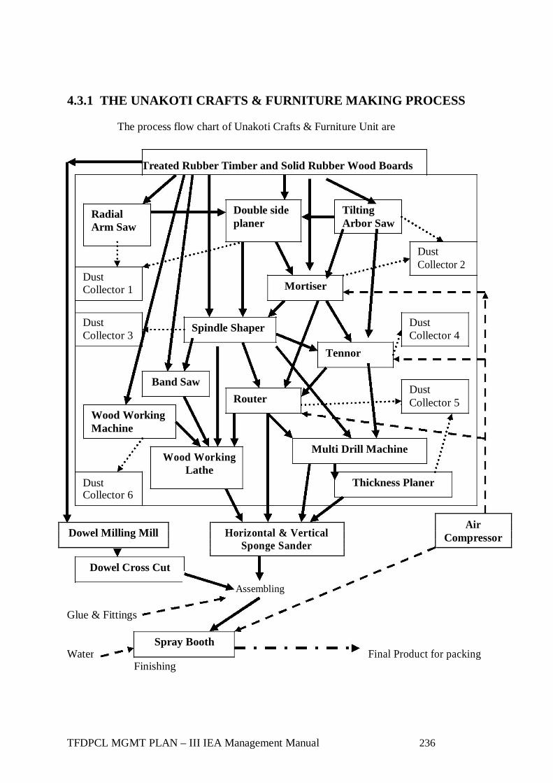


![Operating Procedures 1 G2 - OPERATING PROCEDURES [6 Exam Questions - 6 Groups] G2APhone operating procedures; USB/LSB utilization conventions; procedural.](https://static.documents.pub/doc/80x56/56649e4d5503460f94b4351a/operating-procedures-1-g2-operating-procedures-6-exam-questions-6-groups.jpg)


