TFM Series Water Softener Installation & Operation Manual (Please save for future reference) Thank you for purchasing one of our ENVIROGARD / Rainfresh Water Softeners. We are committed to ensuring that you are totally satisfied. If you have any problems, don’t go back to the store – please contact us ! Most issues can be resolved over the phone. Help Line : 1-800-667-8072 (Monday to Friday 8:30 AM to 5:00 PM EST) www.rainfresh.ca TABLE OF CONTENTS System Specifications ........................................ 2 How Your Water Conditioner Works ................. 2 Safety Precautions ........................................... 2 Cautions Before Installation ............................. 3 Installation ........................................................ 3 a) Electrical Requirements ......................... 3 b) Unpacking the unit ................................. 3 c) Plumbing the Softener ........................... 5 d) Start-up and Programming ..................... 6 a. Control Valve ............................... 7 b. Level 1 Programming ................... 7 c. Level 2 Programming ................... 11 Other Features ................................................. 12 Maintenance ..................................................... 13 Troubleshooting ................................................ 14 Exploded Diagram & Parts List .......................... 15 Warranty........................................................... 16
Transcript
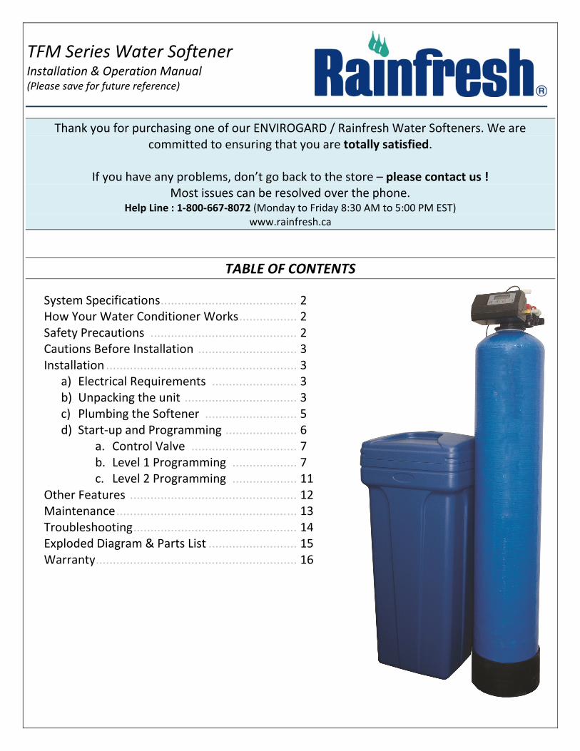
TFM Series Water Softener Installation & Operation Manual (Please save for future reference)
Thank you for purchasing one of our ENVIROGARD / Rainfresh Water Softeners. We are
committed to ensuring that you are totally satisfied.
If you have any problems, don’t go back to the store – please contact us !
Most issues can be resolved over the phone. Help Line : 1-800-667-8072 (Monday to Friday 8:30 AM to 5:00 PM EST)
www.rainfresh.ca
TABLE OF CONTENTS
System Specifications ........................................ 2
How Your Water Conditioner Works ................. 2
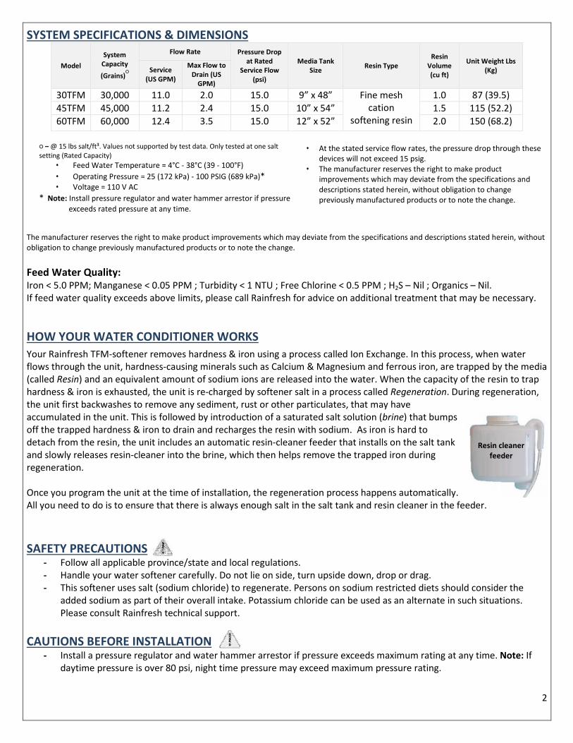
2. Capacity (gal of water that can be used between
regenerations)
3. Volume Remaining (gal of water left before regeneration
begins)
4. Regeneration Time (Time of day when regeneration starts)
5. Last Regeneration Date (Last date when system regenerated)
6. Current Flow Rate (GPM) (flow rate of water being currently
used)
7. Peak Flow Rate (GPM) (Max recorded flow rate of the water)
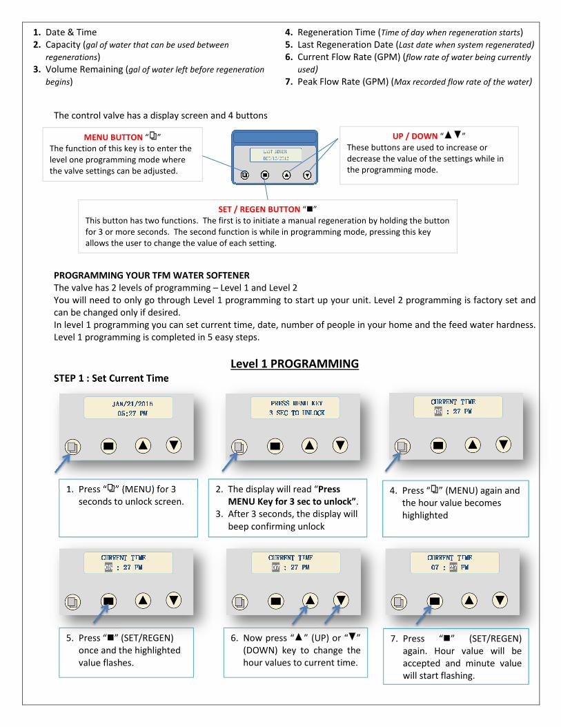
The control valve has a display screen and 4 buttons
PROGRAMMING YOUR TFM WATER SOFTENER
The valve has 2 levels of programming – Level 1 and Level 2
You will need to only go through Level 1 programming to start up your unit. Level 2 programming is factory set and
can be changed only if desired.
In level 1 programming you can set current time, date, number of people in your home and the feed water hardness.
Level 1 programming is completed in 5 easy steps.
Level 1 PROGRAMMING STEP 1 : Set Current Time
1. Press “ ” (MENU) for 3
seconds to unlock screen.
5. Press “�” (SET/REGEN)
once and the highlighted
value flashes.
6. Now press “ ” (UP) or “ ”
(DOWN) key to change the
hour values to current time.
7. Press “�” (SET/REGEN)
again. Hour value will be
accepted and minute value
will start flashing.
MENU BUTTON “ ”
The function of this key is to enter the
level one programming mode where
the valve settings can be adjusted.
SET / REGEN BUTTON “�”
This button has two functions. The first is to initiate a manual regeneration by holding the button
for 3 or more seconds. The second function is while in programming mode, pressing this key
allows the user to change the value of each setting.
UP / DOWN “ ”
These buttons are used to increase or
decrease the value of the settings while in
the programming mode.
JAN/21/2015JAN/21/2015JAN/21/2015JAN/21/2015 05:27 PM05:27 PM05:27 PM05:27 PM 2. The display will read “Press
MENU Key for 3 sec to unlock”.
3. After 3 seconds, the display will
beep confirming unlock
4. Press “ ” (MENU) again and
the hour value becomes
highlighted
PRESS MENU KEY PRESS MENU KEY PRESS MENU KEY PRESS MENU KEY 3 SEC TO UNLOCK3 SEC TO UNLOCK3 SEC TO UNLOCK3 SEC TO UNLOCK CURRENT TIMECURRENT TIMECURRENT TIMECURRENT TIME 05050505 : 27 PM: 27 PM: 27 PM: 27 PM
CURRENT TIMECURRENT TIMECURRENT TIMECURRENT TIME 05050505 : 27 PM: 27 PM: 27 PM: 27 PM CURRENT TIMECURRENT TIMECURRENT TIMECURRENT TIME 00007777 : 27 PM: 27 PM: 27 PM: 27 PM CURRENT TIMECURRENT TIMECURRENT TIMECURRENT TIME 07 : 07 : 07 : 07 : 27272727 PMPMPMPM
8
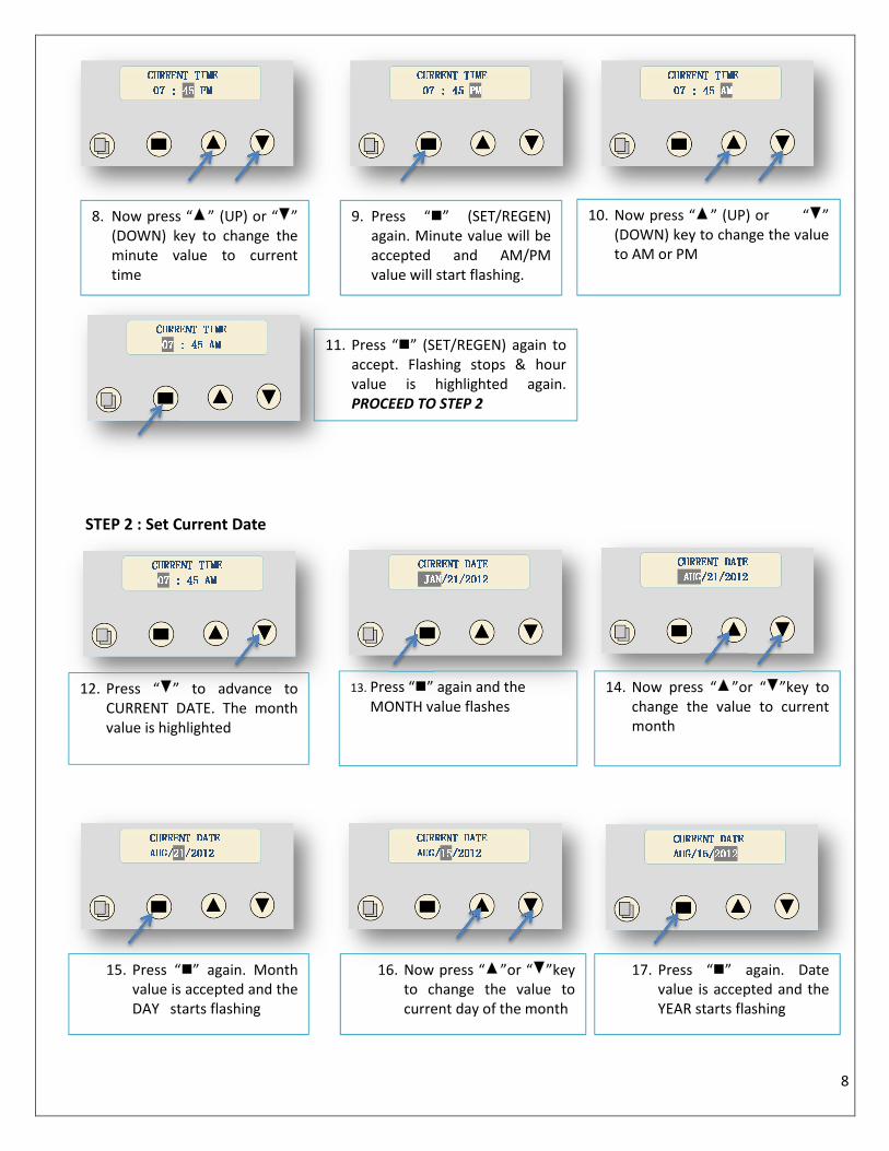
STEP 2 : Set Current Date
13. Press “�” again and the
MONTH value flashes
15. Press “�” again. Month
value is accepted and the
DAY starts flashing
CURRENT TIMECURRENT TIMECURRENT TIMECURRENT TIME 07 : 07 : 07 : 07 : 45454545 PMPMPMPM 8. Now press “ ” (UP) or “ ”
(DOWN) key to change the
minute value to current
time
CURRENT TIMECURRENT TIMECURRENT TIMECURRENT TIME 07 : 07 : 07 : 07 : 45454545 PMPMPMPM 9. Press “�” (SET/REGEN)
again. Minute value will be
accepted and AM/PM
value will start flashing.
10. Now press “ ” (UP) or “ ”
(DOWN) key to change the value
to AM or PM
CURRENT TIMECURRENT TIMECURRENT TIMECURRENT TIME 07070707 : 45 AM: 45 AM: 45 AM: 45 AM
CURRENT TIMECURRENT TIMECURRENT TIMECURRENT TIME 07 : 07 : 07 : 07 : 45454545 AAAAMMMM
11. Press “�” (SET/REGEN) again to
accept. Flashing stops & hour
value is highlighted again.
PROCEED TO STEP 2
CURRENT TIMECURRENT TIMECURRENT TIMECURRENT TIME 07070707 : 45 AM: 45 AM: 45 AM: 45 AM 12. Press “ ” to advance to
CURRENT DATE. The month
value is highlighted
CURRENT DATECURRENT DATECURRENT DATECURRENT DATE JANJANJANJAN/21/201/21/201/21/201/21/2012222 CURRENT DATECURRENT DATECURRENT DATECURRENT DATE AUGAUGAUGAUG/21/201/21/201/21/201/21/2012222 14. Now press “ ”or “ ”key to
change the value to current
month
CURRENT DATECURRENT DATECURRENT DATECURRENT DATE AUGAUGAUGAUG////21212121/201/201/201/2012222 CURRENT DATECURRENT DATECURRENT DATECURRENT DATE AUGAUGAUGAUG////15151515/201/201/201/2012222 16. Now press “ ”or “ ”key
to change the value to
current day of the month
CURRENT DATECURRENT DATECURRENT DATECURRENT DATE AUGAUGAUGAUG////15151515////2012012012012222 17. Press “�” again. Date
value is accepted and the
YEAR starts flashing
9
STEP 3 : Set Number of people in the house
STEP 4: Setting Water Hardness
This value is the hardness value of your water in grains per gallon (GPG). If you have the reading in PPM or mg/L,
simply divide that by 17.1 to get the reading in GPG. You must also add (5 x iron level in PPM) to the hardness value.
HARDNESS VALUE = YOUR WATER HARDNESS + (5 x Iron concentration in PPM)
For example, if your water hardness is 20 GPG and the iron level is 0.3 PPM, the hardness value you enter must be
20 + 5 x (0.3) = 20 + 1.5 = 21.5 GPG
Note: If you do not know your water hardness, please call customer service for details on how to send us a water
sample and receive a free water analysis. In the meantime, you can leave the hardness value at default
setting. You can also visit www.rainfresh.ca for details.
23. Press “�” again to accept the
value. Highlight stops flashing.
CURRENT DATCURRENT DATCURRENT DATCURRENT DATEEEE AUGAUGAUGAUG////15151515////2012012012015555 18. Now press “ ”or “ ”key
to change the value to
current day of the month
NUMBER PEOPLENUMBER PEOPLENUMBER PEOPLENUMBER PEOPLE 4444 19. Press “�” again to accept. Flashing
stops & MONTH value is highlighted
again. PROCEED TO STEP 3
CURRENT DATECURRENT DATECURRENT DATECURRENT DATE AUGAUGAUGAUG////15151515/201/201/201/2015555
20. Press “ ” to advance to
NUMBER OF PEOPLE
NUMBER PEOPLENUMBER PEOPLENUMBER PEOPLENUMBER PEOPLE 4444 NUMBER PNUMBER PNUMBER PNUMBER PEOPLEEOPLEEOPLEEOPLE 3333 21. Press “�” once and the
value flashes
22. Press “ or ” to
change the NUMBER OF
PEOPLE in your home. NUMBER PEOPLENUMBER PEOPLENUMBER PEOPLENUMBER PEOPLE 3333 WATER HARDNESSWATER HARDNESSWATER HARDNESSWATER HARDNESS 20202020 GPGGPGGPGGPG 24. Press “ ” to advance to WATER
HARDNESS. The value is highlighted
PROCEED TO STEP 4
10
STEP 5: Setting Vacation Mode
This function may be activated during a prolonged absence, such as a vacation for more than 2 weeks. The system
will perform a brief backwash and rinse based on advanced setting. The purpose is to keep the water fresh in the
softener tank and plumbing system.
By selecting the vacation mode, the normal display will show the following in sequence
- Current date and time
- Regeneration days : 07 days
- Remaining days : __ Days
- Regeneration time : 2:00 AM
- Last Regeneration date :
- Current Flow Rate : __ GPM
- Peak Flow Rate : __ GPM
After returning from vacation, reset the VACATION MODE to “NO”.
YOUR UNIT IS NOW READY FOR SERVICE
Level 2 PROGRAMMING (OPTIONAL SETTINGS)
NOTE : Under normal use there is no need to change the settings under level 2 programming. You can, however,
change the default settings if required. CAUTION: DO NOT CHANGE LEVEL 2 SETTINGS WITHOUT CONSULTING
RAINFRESH TECHNICIAN (1-800-667 8072). Wrongly changing the settings can result in malfunction of the unit.
When the Level 2 Master Programming Mode is entered, all available option setting displays may be viewed and set
as needed. Depending on current option settings, some parameters cannot be viewed or set.
26. Now press “ or keys to
set feed water hardness &
press “�” again to accept
25. Press “�” again. HARDNESS
value starts flashing
WATER HARDNESSWATER HARDNESSWATER HARDNESSWATER HARDNESS 15151515 GPGGPGGPGGPG VACATION MODEVACATION MODEVACATION MODEVACATION MODE YESYESYESYES NONONONO 28. Now press “ ” key to advance
to VACATION MODE. Press “ ”
again to exit or press “�” to set
vacation mode.
VACATION MODEVACATION MODEVACATION MODEVACATION MODE YESYESYESYES NONONONO 29. To set vacation mode, press
1 System Language English Spanish French Set to French if desired.
Spanish not enabled
2 Valve Operation Softener Filter Iron
Filter Leave at default setting
3 Regeneration
Mode
Meter
Delayed
Meter
Override
Calendar
Clock
Meter
Immediat
e
Leave at default setting
4 Regeneration
Time 2:00 AM
The unit is factory set to regenerate
at 2:00 AM on the day of
regeneration. You can change to
another time if desired.
5 Capacity
Calculation Automatic Manual
Automatic (recommended). Change
to manual settings if desired.
6 Resin Volume
For 30TFM unit, set resin volume at 1.0 cu ft
For 45TFM unit, set resin volume at 1.5 cu ft
For 60FM unit, set resin volume at 2.0 cu ft
7 Salt Setting Leave at default setting. For best results set between 12 lbs/ft³ & 15 lbs/ft³. If you are
using a resin-cleaner as described on page 2, then you can lower it to 9 lbs/ft³.
8 Refill Flow Rate 0.7 GPM Leave at default setting
9 Unit Capacity
For 30TFM, default = 30,000
For 45TFM, default = 45,000
For 60TFM, default = 60,000
10 Reserve Capacity 75
gal/person
Increase or decrease value as
desired
11 Capacity Will be automatically calculated if step 5 is set for “Automatic”. This shows the total
gallons of soft water available before the unit will regenerate.
2. Press “ ” (MENU) for 3
seconds to unlock screen.
JAN/21/2015JAN/21/2015JAN/21/2015JAN/21/2015 05:27 PM05:27 PM05:27 PM05:27 PM 4. The display will read “Press
MENU Key for 3 sec to unlock”.
5. After 3 seconds, the display will
beep confirming unlock
PRESS MENU KEY PRESS MENU KEY PRESS MENU KEY PRESS MENU KEY 3 SEC TO UNLOCK3 SEC TO UNLOCK3 SEC TO UNLOCK3 SEC TO UNLOCK SYSTEM LANGUAGESYSTEM LANGUAGESYSTEM LANGUAGESYSTEM LANGUAGE ENGLISHENGLISHENGLISHENGLISH 4. Press and hold “ ”
together for three seconds
to enter Level Two Master
Programming.
12
Salt Setting (lbs/cu ft)
Model 6.0 8.0 10.0 12.0 15.0
30TFM 2.9 3.8 4.8 5.7 7.1
45TFM 4.2 5.7 7.1 8.5 10.7
60TFM 5.7 7.6 9.6 11.4 14.2
Table 1 : Refill time (in minutes) for various salt settings using Sodium Chloride
Disinfecting the Softener
It is possible that during shipping, storage & installing, bacteria can go into the unit.
Therefore, as a good installation practice, it is recommended that the softener be disinfected
prior to use. To disinfect, open the lid of the brine well in the salt tank and add approx. 3
tablespoons of fresh common household bleach. Replace lid & proceed to next step.
Manual Regeneration
If screen is locked, press “ MENU” for 3 seconds to unlock. To initiate an immediate regeneration, press the SET/REGEN
button for 3 seconds, an option for “Delayed” or “Immediate” regeneration will appear. Press the SET/REGEN button
again and “Delayed” will begin flashing. Now press the down arrow button and “Immediate” will flash. Press the
SET/REGEN button once and then press the menu button once. Valve will immediately start manual regeneration.
YOUR UNIT IS NOW READY FOR SERVICE
OTHER FEATURES Control Operation During a Power Failure
In the event of a power failure, the valve will keep track of the time and day for 48 hours. The programmed settings
are stored in a non-volatile memory and will not be lost during a power failure. If power fails while the unit is in
regeneration, the valve will finish regeneration after power is restored. If the valve misses a scheduled regeneration
due to a power failure, it will queue regeneration at the next regeneration time once power is restored.
Safety Float
The brine tank is equipped with a safety float which prevents your brine tank from overfilling as a result of a
malfunction such as a power failure.
New Sounds
You may notice new sounds as your water softener operates. The regeneration cycle lasts approximately 2 hours.
During this time, you may hear water running intermittently to the drain.
Manual Bypass
In the case of emergency, such as an overflowing brine tank, you can isolate your water softener from the water
supply using the bypass valve located at the back of the control. To resume soft water service, open bypass valve by
rotating the knobs counterclockwise.
12 Backwash 05 Increase to 10 if water has lot of dirt
or rust
13 Brine / Rinse 50 Increase to 60 if water is more than
15 grains hard
14 Rapid Rinse 5 Increase to 10 if you want a longer
rinse time after regeneration
15 Refill For REFILL settings based on your chosen salt settings, please refer to Table 1 below
16 Restore Default NO
Leave at default. Change only if you
would like to re-start programming
from the beginning
Open this lid &
pour bleach inside
13
MAINTENANCE Adding Salt
Fill the salt tank only with nugget or pellet salt that is specifically for water softeners only. DO NOT USE rock salt,
road salt or other types of impure salts. Use only high grade water softener salt (Sodium Chloride). You can use
Potassium Chloride but you will need to increase salt settings (see page 12). Check the salt level monthly. It is
important to ALWAYS maintain the salt level above the water level. To add salt, simply slide open the salt tank lid
and add the salt directly into the brine tank. Be sure the brine well cover is on and fill only to the height of the brine
well. The salt tank should never be empty.
DO NOT OVERFILL THE SALT TANK TO THE TOP. 2-3 bags at a time are enough.
YOU WILL NOT BE ABLE TO SEE THE WATER ONCE YOU ADD A COUPLE OF BAGS OF SALT. IF YOU WANT
TO CHECK THE WATER LEVEL, OPEN THE LID ON THE BRINE WELL.
Preventing and breaking a Salt Bridge
Humidity or wrong type of salt may create a cavity between the water and the salt. This action,
known as “bridging”, prevents the brine solution from being made, leading to your water supply
being hard. If you suspect salt bridging, pour some warm water over the salt to break up the
bridge. Allow four hours to produce a brine solution, and then manually regenerate the softener.
This should always be followed up by allowing the unit to use up any remaining salt and then
thoroughly cleaning out the brine tank.
If you are unable to break the bridge this way, take a strong rod and carefully push down the salt,
working it up and down. Do not pound on the walls of the tank. If the wrong kind of salt has been
used, take it out and fill with nugget or pellet salt.
Care of Your Softener
To retain the attractive appearance of your new water softener, clean occasionally with mild
soap solution. Do not use abrasive cleaners, ammonia or solvents.
Cleaning the Injector Assembly
Sediment, salt and silt will restrict or clog the injector. A clean water supply and pure salt will prevent this from
happening. The injector assembly is located on the right side of the control valve. This assembly is easy to clean.
Shut off the water supply to your softener and reduce the pressure by opening a cold soft water faucet. Using a
screwdriver, remove the two screws holding the injector cover to the control valve body. Carefully remove the
assembly and disassemble as shown in Figure 6. The injector orifice is removed from the valve body by carefully
turning it out with a large screwdriver. Remove the injector throat the same way. Carefully flush all parts including
the screen. Use a mild acid such as vinegar to clean the small holes in the orifice and throat.
Reassemble using the reverse procedure.
Injector Screen
14
TROUBLESHOOTING Please review the following troubleshooting guide before calling customer service.
• If you are unable to resolve the problem using the guide below, please call customer service at
1800 667 8072 (Mon to Fri 8:30 AM to 5 PM EST)
• Please have your receipt & model number ready before you call. Customer service may request
digital pictures of your installation in order to help troubleshoot the unit.
ISSUE POSSIBLE CAUSE POSSIBLE SOLUTION
A. Unit fails to start a
regeneration cycle
1. No power supply
2. Defective circuit board
1. Check electrical service & re-set time of day
2. Replace faulty parts
B. Softened water is still hard or
leaves iron stains
1. Bypass valve is closed
2. No salt in salt tank
3. Plugged injector/screen
4. Brine refill settings wrong
5. Leak between valve and riser
tube
6. Internal valve leak
1. Open bypass valve
2. Add salt to salt tank
3. Clean parts (see page 9)
4. Correct brine refill settings (Table 1)
5. Check if riser is cracked or O-ring is damaged.
Replace faulty parts
6. Replace valve seals, spacer and piston
assembly
C. Salt use is high 1. Refill time is too high 1. Correct brine refill settings (table 1)
D. Low water pressure 1. Iron or scale buildup in line
feeding softener
2. Iron buildup inside valve or
tank
3. Inlet of control valve plugged
due to dirt
1. Clean/replace supply line
2. Clean control valve & add resin cleaner to clean
bed. Increase regeneration frequency
3. Clean control valve inlet
E. Resin in drain line 1. Air in water system
2. Incorrect or missing drain line
flow control (DLFC)
1. Check well system for proper air elimination
2. Check and replace DLFC
F. Too much water in brine
tank
1. Plugged injector or screen
2. Plugged brine valve
3. DLFC plugged
1. Clean parts (page 9)
2. Clean parts
3. Clean DLFC
G. Unit fails to draw brine 1. DLFC plugged
2. Injector or screen is plugged
3. Inlet pressure too low
4. Internal valve leak
1. Clean DLFC
2. Clean parts
3. Increase min pressure to at least 25 psi
4. Replace seals, spacer & piston assembly
H. Unit cycles continuously 1. Defective circuit board 1. Replace faulty parts
I. Water flows to drain
continuously
1. Valve settings incorrect
2. Internal leak
1. Check valve settings
2. Replace seals, spacer & piston assembly
J. Softener is leaking between
the bypass valve and control
valve
1. Possible O-ring leak
Check the metal adapter clips holding the 2
components together and tighten if necessary.
Replace O-rings as required
K. Softener is always flashing
through different pieces of
information
This is normal No action required
L. I am having difficulty accessing
level 2 programming?
Unlock the screen by pressing and holding the
menu button for 3 seconds. Press and hold both
up and down arrows until the system language
appears. See video at
http://rainfresh.ca/how_to_videos.php
M. My display screen is blank 1. Power cord may be unplugged
from either adapter or receptacle
2. Defective circuit board
1. Re-connect power cord
2. Call Rainfresh to receive new circuit board with
replacement instructions
Need help troubleshooting? Call Toll Free 1-800-667-8072 Monday to Friday 8:30 AM to 5 PM EST.
15
PARTS LIST
Item
No. Part No. Description Qty
A01 05056087 Screw - M5x12
(Hexagon) 3
A02 05056088
Screw - M5x16
(Hexagon with
washer)
2
A03 05056047 End plug retainer 1
A04 05030002 Piston rod 1
A05 05056097 Piston pin 1
A06 05056023 End plug 1
A07 05056070 Quad ring 2
A08 05056024 End plug washer 1
A09 05056022 Piston retainer 1
A10 05056181 Piston (electrical) 1
A11 05056104 Muffler 1
A12 05056021 Spacer 4
A13 05056073 Seal 5
A14 05030001 Valve body 1
A15 05056129 O-ring φ 23x3 4
A16 05056025 Adaper coupling 2
A17 05056044 Adaptor clip 2
A18 05056090
Screw-ST4. 2x13
(Hexagon with
washer)
2
A19 21709003 Secure clip 2
A20 05056140 Valve connector 1
A21 05056065 O-ring φ 23.6x2.65 2
A22 21319006 Screw adaptor 2
A23 05056508
Screw M5x12
(Hexagon with
washer)
5
A24 05030004 End cover 1
A25 05030013 O-ring φ 30x2.65 1
A26 13000426 Screw-ST2. 9x13
(Large) 2
A27 07060007 Valve bottom
connector 1
A28 26010103 O-ring φ 25x3.55 1
A29 05056063 O-ring φ
78.74x5.33 1
A30 05056086
Screw - M5x30
(Hexagon with
washer)
2
A31 05056029 Injector cover 1
A32 05056072 O-ring φ 24x2 1
A33 05056027 Injector nozzle 1
A34 05056103 Injector screen 1
A35 05056028 Injector throat 1
A36 05056035 BLFC button
retainer 1
A37 05056191 BLFC - 2# 1
A38 05056138 O-ring φ 14x1.8 1
A39 05056100B BLFC fitting 1
A40 05056106 Brine line screen 1
A41 05056107 BLFC tube insert 1
16
Limited Warranty:
This “TFM” Series Softener System is warranted to the original
Consumer purchaser for a period of one (1) year, from the
date of purchase, against defects in materials or
workmanship. The electronic controls and mineral tank are
warranted for 5 and 10 years respectively against defects in
materials or workmanship. The company's obligation under
this warranty shall consist of repair or replacement, at its
option, of any part found by company inspection to be
defective, provided that the product has not been misused,
abuse, altered or damaged by Consumer with respect to the
original installation, as determined by the company. This
warranty will not apply if water passing through the System
has a) Turbidity / Suspended Solids > 5 ppm (mg/l). b)
Hydrogen Sulphide concentrations greater than 0.05 ppm
(0.05 mg/l). c) Iron concentration greater than 5.0 ppm (0.3
mg/l), d) Manganese greater than 0.05 ppm (0.05 mg/l),
e) Tannins or colour or other feed water conditions that
exceed the water quality requirements of the softener. This
limited Warranty applies only to a unit when returned to the
Warrantor at the owner’s expense and in accordance with
shipping instructions received from the Warrantor. This
warranty does NOT cover, and is intended to exclude, any
liability on the part of Envirogard for any incidental damages,
consequential damages, labour charges or any other costs
incurred in connection with the purchase, installation, use,
maintenance or repair of the system whether under this
warranty or any other warranty implied by law. Some
provinces/states do not allow the exclusion of incidental or
consequential damages, so the above limitation or exclusion
may not apply to you. This warranty gives you specific legal
rights and you may also have other rights, which vary from
province/state to province/state. This warranty applies only
to water filter/systems purchased in Canada or the U.S.A.
Envirogard Products Limited 6-446 Major Mackenzie Drive East, Unit 6