Series TFX BTU-Pro Flowmeters integrate advanced non-invasive flow measurement technology and precision differential temperature circuitry – providing an energy measurement and management system with unsurpassed accuracy, versatility, low cost of installation and low cost of ownership. These systems are ideal for energy billing or efficiency optimization in liquid thermal energy systems. Dynasonics offers three BTU-Pro measurement systems: Series TFXD, TFXM and TFXP. Series TFXD and TFXM are designed for fixed installation in HVAC systems. TFXD is a low-cost, single-pipe device and is available with or without a local display and keypad. TFXM is utilized for multiple-pipe installations or where mathematical manipulation – sum, average or difference – of measured flows between pipes is required. TFXP is battery-powered, rugged and portable. It is designed for survey measurements, fixed-mount flowmeter calibration and periodic system balancing. All TFX models incorporate an infrared interface and Windows ® ULTRALINK ™ software utility. The utility allows simple in-field programming, calibration, diagnostics and software upgrades. All systems utilize Dynasonics’ proprietary dual time-base time expansion software algorithm, digital cross-correlation and optically-isolated, field-replaceable communication modules. TFX flow measurement systems are a cost effective, versatile investment that can be readily configured for piping from 1” [25mm] to 100” [2540mm]. All BTU-Pro meters display thermal energy units (BTU, CAL, WATT) as well as standard volumetric flow units (GAL, LITER, BARRELS, etc.). LIQUID THERMAL ENERGY FLOWMETERS FEATURES Series TFX BTU-Pro Non-invasive clamp-on transducers and RTDs are simple and cost efficient to install. Since the sensors do not contact the liquid, fouling and maintenance are eliminated. Field replaceable, optically isolated output and communications modules eliminate ground loops and reduce the probability of significant damage in the event of an electrical surge. Low power consumption. Typical operating power for the TFX system is less than 2.5W, allowing extended operation on UPS and battery operated power sources. The measurement range of the TFX system includes zero flow – this feature reduces billing errors. Reading accuracy and reliability, especially at low flow rates, are improved versus mechanical, DP and vortex shedding flowmeter performance. The differential temperature module, required for heat flow measurement, provides direct connection to 1000 Ω platinum resistance temperature detectors (RTDs). Clamp-on or insertion type RTDs can be utilized. Rate and totalizer units include BTUs, calories and Watts. Unit selection is user configured with keypad entries or with the provided Windows ® configuration software. A variety of output and communication modules is available including 200,000-event data logger, 4-20 mA, rate pulse, dual-relay, RS232 and RS485. An integral optical interface and optional Windows ® software utility provide complete control of system configuration, calibration and diagnostics – without opening the NEMA 4X enclosure. DIVISION OF RACINE FEDERATED INC. TM TFXM TFXP TFXD
Transcript
Series TFX BTU-Pro Flowmeters integrate advanced non-invasiveflow measurement technology and precision differential temperaturecircuitry – providing an energy measurement and managementsystem with unsurpassed accuracy, versatility, low cost of installationand low cost of ownership. These systems are ideal for energy billingor efficiency optimization in liquid thermal energy systems.
Dynasonics offers three BTU-Pro measurement systems: SeriesTFXD, TFXM and TFXP. Series TFXD and TFXM are designed forfixed installation in HVAC systems. TFXD is a low-cost, single-pipedevice and is available with or without a local display and keypad.TFXM is utilized for multiple-pipe installations or where mathematicalmanipulation – sum, average or difference – of measured flowsbetween pipes is required. TFXP is battery-powered, rugged andportable. It is designed for survey measurements, fixed-mountflowmeter calibration and periodic system balancing. All TFXmodels incorporate an infrared interface and Windows®
ULTRALINK™ software utility. The utility allows simple in-fieldprogramming, calibration, diagnostics and software upgrades. Allsystems utilize Dynasonics’ proprietary dual time-base timeexpansion software algorithm, digital cross-correlation andoptically-isolated, field-replaceable communication modules.
TFX flow measurement systems are a cost effective, versatileinvestment that can be readily configured for piping from 1”[25mm] to 100” [2540mm]. All BTU-Pro meters display thermalenergy units (BTU, CAL, WATT) as well as standard volumetricflow units (GAL, LITER, BARRELS, etc.).
LIQUID THERMAL ENERGY FLOWMETERS
FEATURES
Series TFX BTU-Pro
Non-invasive clamp-on transducers and RTDs are simple and costefficient to install. Since the sensors do not contact theliquid, fouling and maintenance are eliminated.
Field replaceable, optically isolated output and communicationsmodules eliminate ground loops and reduce the probability ofsignificant damage in the event of an electrical surge.
Low power consumption. Typical operating power for the TFX systemis less than 2.5W, allowing extended operation on UPS andbattery operated power sources.
The measurement range of the TFX system includes zeroflow – this feature reduces billing errors. Reading accuracyand reliability, especially at low flow rates, are improved versusmechanical, DP and vortex shedding flowmeter performance.
The differential temperature module, required for heat flowmeasurement, provides direct connection to 1000 Ω platinumresistance temperature detectors (RTDs). Clamp-on or insertiontype RTDs can be utilized.
Rate and totalizer units include BTUs, calories and Watts. Unitselection is user configured with keypad entries or with the providedWindows® configuration software.
A variety of output and communication modules is availableincluding 200,000-event data logger, 4-20 mA, rate pulse,dual-relay, RS232 and RS485.
An integral optical interface and optional Windows® software utilityprovide complete control of system configuration, calibration anddiagnostics – without opening the NEMA 4X enclosure.
D I V I S I O N O F R A C I N E F E D E R A T E D I N C .
TM
TFXM
TFXP TFXD
TERMINOLOGY AND DEFINITIONS
Series TFX BTU-Pro
ULTRALINK™ SOFTWARE UTILITY
Real-Time Infrared Communications. Configuration and calibration are quick andsimple using ULTRALINK™ and your PC. Dynasonics Infrared Serial Adapter (P.N.D005-2115-001) allows full programming access without the need to open the TFXenclosure or connect wires.
Designed with the user/operator in mind, configuration and calibration of transittime ultrasonic flowmeters have never been as simple and straight forward aswith Series TFX. Integration of your PC, the TFX flowmeter and ULTRALINK™
provides the ultimate in operator control. ULTRALINK™ is a Windows®
95/98/2000/XP/ME/NT software utility that communicates with TFX flowmetersthrough a PC serial communications port and infrared serial adapter (DynasonicsP.N. D005-2115-001 shown below). Since the communication link is infrared light,the user need only be within 10 feet [3 meters] of the TFX meter – interconnectionwires and opening of the meter enclosure are not necessary.
Order Dynasonics P.N. D005-2115-100. Kit includes ULTRALINK™ on a3.5 inch diskette and one infrared serial adapter.
Note: Model TFXD2, TFXM and TFXP (models with integral keypad and display) donot require ULTRALINK™ or the use of a computer for configuration. Model TFXD1(model without keypad and display) does require the software and computer forsystem configuration. The software and computer are requirements forin-field calibration of TFX systems and for RTD calibration.
BTU (British Thermal Unit): The amount of heat required to raise thetemperature of one pound of water by one degree Fahrenheit.
Kilo-Calorie (K-Cal): The amount of heat required to raise the temperatureof one kilogram of water by one degree Celsius.
Watt: A unit of energy delivery equal to 1 Joule/second.
Mass Flow Rate: The gravimetric weight per unit time of fluid flowingwithin a closed conduit. Volumetric flow (gallons, liters, etc.) is converted tomass flow (pounds, grams, etc.) before conversion to energy units.
Temperature Differential: The relative difference in temperature betweentwo elements. In liquid thermal energy systems this would be the temperaturedifference between the supply and return pipe lines.
Specific Heat Capacity: The amount of energy that is required to eitherincrease or decrease the temperature of a unit mass by one unit.
Thermal Energy Rules of ThumbFor heating or cooling water:BTU/Hour = 500 x GPM x ∆T (temperature difference, degrees ˚F.)For heating air with water coils:CFM x ∆T air = 463 x GPM x ∆T waterFor heating or cooling water with water:GPM1 = GPM2 x (∆T water2 ˚F. / ∆T water1 ˚F.)
Thermal Energy Conversions3.968 BTU/Hour = 1 Kilo-Calories/Hour or Therms3.413 BTU/Hour = 1 Watts or Joules/Second12,000 BTU/Hour = 1 Tons33,475 BTU/Hour = 1 HP (Boiler)
1 Gallon of Water = 8.3453 Pounds = 3.7854 Kilograms1 Liter of Water = 0.2642 Gallons = 2.205 Pounds = 1 Kilogram
GPM = 2.448 x I.D.(inches) x Feet per SecondLPM = 0.047 x I.D.(mm) x Meters per Second
˚C = 0.555 x (˚F - 32) ˚F = (1.8 x ˚C) + 32
Transmitter Type1) Blind2) Rate and Totalizer Display
Power SupplyA) 115 VACB) 230 VACC) 100 VACE) 9-28 VDC
TFX transit time flowmeters utilize two transducers, shown as elements Aand B in Figure 1, which function as both ultrasonic transmitters andreceivers. The transducers are clamped on the outside of a closed pipe at aspecific distance from each other. (The transducers can be mounted inV-mode as shown in Figure 1, W-mode where the sound transverses thepipe four times, or in Z-mode where the transducers are mounted on oppositesides of the pipe. This selection is based on pipe and liquid characteristics.)The flowmeter operates by alternately transmitting and receiving a frequencymodulated burst of sound energy between the two transducers. The burst isfirst transmitted in the direction of fluid flow and then against fluid flow.Since sound energy in a moving liquid is carried faster when it travels in thedirection of fluid flow (downstream) than it does when it travels againstfluid flow (upstream), a differential in the times of flight will occur. If thefluid is not moving, the time of flight difference will be zero and the flowmeterwill indicate zero flow. The sound’s time of flight is accurately measured inboth directions and the difference in time of flight is calculated. The liquidvelocity (V) inside the pipe can be related to the difference in time of flight(dt) through the following equation: V = K*D*dt, where K is a constant andD is the distance between the transducers.
Heat delivered calculations are made by multiplexing temperature informationfrom two precision 1000 Ω RTDs, one located at the supply line to a locationand the other at the return line. Heat delivered to a location is calculated asHEAT = Q*SH*(TEMP1 - TEMP2), where Q is the mass flow rate, SH is thespecific heat of the liquid and TEMP1 and TEMP2 are the supply and returntemperature measurements.
PART NUMBER CONSTRUCTION
TRANSIT TIME - HEAT FLOW
DTFXP Replacement Parts Part Number
Data Logger Module D020-1045-104
Padded carrying case D003-1012-002
Transducers, set of two D071-0105-000
Transducer Cable, 20 ft. [6m] D005-2112-020
Acoustic Grease D002-2011-001
Mounting Track D010-2102-010
Power Converter 115V D005-2502-001(Two Spades - Round Ground)
Power Converter 230V D005-2502-002(Two Round)
Power Converter 230V (UK) D005-2503-003(Three Rectangular)
Power Converter Universal D005-2503-005(Use For 100V Power)
MULTIPLE-PIPE, FIXED-MOUNT
(REQUIRES TRANSDUCER, SEE BELOW)SINGLE-PIPE, PORTABLE
(TRANSDUCER INCLUDED)SINGLE-PIPE, FIXED-MOUNT
(REQUIRES TRANSDUCER, SEE BELOW)
TRANSDUCER
DTT
Pipe Size: O.D.N) Standard [CPVC, Ultem®]H) High Temp [Stainless, Vespel®]
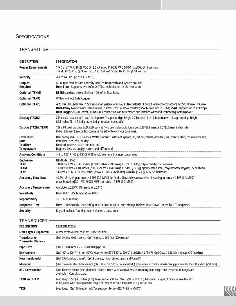
Environment (Std) -40° to 300°F [-40° to 150°C]; (Opt) -40° to 450°F [-40° to 230°C] (Std) NEMA 6 [IP-67]; (Opt) Class I, II, III, Div 1, Groups C-G (pending)
Housing Material (Std) CPVC, nylon, Ultem®; (Opt) Stainless, nickel-plated brass and Vespel®
Mounting (Std) Stainless steel hose clamps (P.N. D002-2007-001), not included; (Opt) aluminum track assembly for pipes smaller than 10 inches [250 mm]
RTD Construction (Std) Thermal-ribbon type, platinum, 1000 Ω; three-wire; (Opt) Alternate mounting, lead length and temperature ranges are available – Consult factory.
TFXD and TFXM Lead length: (Std) 40 inches [1 m]; Temp. range: -58˚ to +266˚F [-50 to +130˚C]; Additional lengths of cable require the RTDto be joined with an appropriate length of three-wire shielded cable at a junction box.
TFXP Lead length (Std) 20 feet [6.1 m]; Temp range: -80˚ to +392˚F [-62 to +200˚C]
SPECIFICATIONS
TRANSMITTER
DESCRIPTION SPECIFICATION
Power Requirements TFXD and TFXP: 10-28 VDC @ 2.5 VA max. 115/230 VAC 50/60 Hz ±15% @ 5 VA max.TFXM: 10-28 VDC @ 8 VA max.; 115/230 VAC 50/60 Hz ±15% @ 14 VA max
Velocity -40 to +40 FPS [-12 to +12 MPS]
Outputs All output modules are optically isolated from earth and system grounds. Required Heat Flow; Supports two 1000 Ω RTDs, multiplexed, 12-bit resolution
Optional (TFXM) RS485 standard; choice of either 4-20 mA or Dual-Relay
Optional (TFXP) With or without Data Logger
Optional (TFXD) 4-20 mA 800 Ohms max.; 12-bit resolution; passive or active; Pulse Output FET output (open collector action), 0-2,500 Hz max., 1 A max.; Dual-Relay Two separate Form C relays, 200 VAC max. @ 0.5 A resistive; RS232 data rate to 57.6K; RS485 supports up to 119 drops; Data Logger 200,000-event, 16-bit, DB-9 connection, can be removed and installed without disconnecting system power
Display [TFXD2] 2 line x 8 character LCD, back lit. Top row: 7-segment digit height 0.7 inches [18 mm], Bottom row: 14-segment digit height0.35 inches [9 mm]; 8 digit rate, 8 digit totalizer (resettable)
Display [TFXM, TFXP] 128 x 64 pixel graphics LCD, LED back lit. Two user selectable font sizes 0.35" [8.9 mm] or 0.2" [5.0 mm] 8 digit rate,8 digit totalizer (resettable); configure for either two or four data lines.
Flow Units User configured - BTU, Calories, Watts (standard units: feet, gallons, ft3, mil-gal, barrels, acre-feet, lbs., meters, liters, m3, mil-liters, Kg)Rate Rate time: sec, min, hr, day Totalizer Forward, reverse, batch and net totalTemperature Degrees Celsius; supply, return, and differential
Ambient Conditions -40 to 185°F [-40 to 85°C], 0-95% relative humidity, non-condensing
Enclosure NEMA 4X, [IP-66]TFXD 7.00H x 5.75W x 3.88D inches [178H x 146W x 99D mm]; 2.8 lbs. [1.3 Kg]; polycarbonate, SS hardwareTFXM 11.0H x 11.4W x 4.1D inches [280H x 290W x 104D mm]; 11.5 lbs. [5.2 Kg]; epoxy coated steel, polycarbonate keypad, SS hardwareTFXP 14.00W x 6.06H x 10.56D inches [356W x 154H x 268D mm]; 14.8 lbs. [6.7 Kg]; ABS, SS hardware
Accuracy Flow Rate ±0.5% of reading at rates > 1 FPS [0.3 MPS] for field calibrated systems; ±1% of reading at rates > 1 FPS [0.3 MPS]uncalibrated; ±|0.01 FPS [0.003 MPS]| at rates < 1 FPS [0.3 MPS]
Accuracy Temperature Absolute: ±0.25°C, Differential: ±0.1°C
Sensitivity Flow: 0.001 FPS Temperature: 0.05°C
Repeatability ±0.01% of reading
Response Time Flow: 1-10 seconds, user configured, to 90% of value, step change in flow. Heat Flow: Limited by RTD response.
Security Keypad lockout, four-digit user selected access code
TRANSDUCER
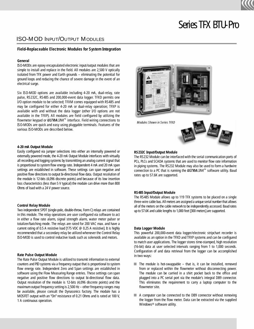
GeneralISO-MODs are epoxy encapsulated electronic input/output modules that aresimple to install and replace in the field. All modules are 2,500 V opticallyisolated from TFX power and Earth grounds – eliminating the potential forground loops and reducing the chance of severe damage in the event of anelectrical surge.
Six ISO-MOD options are available including 4-20 mA, dual-relay, ratepulse, RS232C, RS485 and 200,000-event data logger. TFXD permits oneI/O option module to be selected; TFXM comes equipped with RS485 andmay be configured for either 4-20 mA or dual-relay operation; TFXP isavailable with and without the data logger (other I/O options are notavailable in the TFXP). All modules are field configured by utilizing theflowmeter keypad or ULTRALINK™ interface. Field wiring connections toISO-MODs are quick and easy using pluggable terminals. Features of thevarious ISO-MODs are described below.
4-20 mA Output ModuleEasily configured via jumper selections into either an internally powered orexternally powered mode, the 4-20 mA Output Module interfaces with virtuallyall recording and logging systems by transmitting an analog current signal thatis proportional to system flow energy rate. Independent 4 mA and 20 mA spansettings are established in software. These settings can span negative andpositive flow directions to output bi-directional flow data. Output resolution ofthe module is 12-bits (4,096 discrete points) and because of its low insertionloss characteristics (less than 5 V typical) the module can drive more than 800Ohms of load with a 24 V power source.
Control Relay ModuleTwo independent SPDT (single-pole, double-throw, Form C) relays are containedin this module. The relay operations are user configured via software to actin either a flow rate alarm, signal strength alarm, water meter pulser ortotalizer/batching mode. The relays are rated for 200 VAC max. and have acurrent rating of 0.5 A resistive load [175 VDC @ 0.25 A resistive]. It is highlyrecommended that a secondary relay be utilized whenever the Control RelayISO-MOD is used to control inductive loads such as solenoids and motors.
Rate Pulse Output ModuleThe Rate Pulse Output Module is utilized to transmit information to externalcounters and PID systems via a frequency output that is proportional to systemflow energy rate. Independent Zero and Span settings are established insoftware using the Flow Measuring Range entries. These settings can spannegative and positive flow directions to output bi-directional flow data.Output resolution of the module is 12-bits (4,096 discrete points) and themaximum output frequency setting is 2,500 Hz – other frequency ranges maybe available, please consult the Dynasonics factory. The module has aMOSFET output with an "On" resistance of 0.21 Ohms and is rated at 100 V,1 A continuous operation.
RS232C Input/Output ModuleThe RS232 Module can be interfaced with the serial communication ports ofPCs, PLCs and SCADA systems that are used to monitor flow rate informationin piping systems. The RS232 Module may also be used to form a hardwireconnection to a PC that is running the ULTRALINK™ software utility. Baudrates up to 57.6K are supported.
RS485 Input/Output ModuleThe RS485 Module allows up to 119 TFX systems to be placed on a singlethree-wire cable bus. All meters are assigned a unique serial number that allowsall of the meters on the cable network to be independently accessed. Baud ratesup to 57.6K and cable lengths to 1,000 feet [300 meters] are supported.
Data Logger ModuleThis powerful 200,000-event data logger/electronic stripchart recorder isavailable as an option in the TFXD and TFXP systems and can be configuredto match user applications. The logger stores time-stamped, high resolution(16-bit) data at user selected intervals ranging from 1 to 1,000 seconds.Configuration of and data retrieval from the logger can be accomplishedin two ways:
The module is hot-swappable – that is, it can be installed, removed from or replaced within the flowmeter without disconnecting power. The module can be carried in a shirt pocket back to the office and plugged into a PC serial port via the module's integral DB9 connector. This eliminates the requirement to carry a laptop computer to the flowmeter site.
A computer can be connected to the DB9 connector without removing the logger from the flow meter. Data can be extracted via the supplied Windows® software utility.
ISO-MOD INPUT/OUTPUT MODULES
Field-Replaceable Electronic Modules for System Integration
Series TFX BTU-Pro
Modules Shown in Series TFXD
Series TFX BTU-ProDIMENSIONAL SPECIFICATIONS
TOP VIEWOF PIPE
TOP VIEWOF PIPE
FORM TFX BTU-PRO 3/02
D I V I S I O N O F R A C I N E F E D E R A T E D I N C .
TM
2200 South Street Racine, WI 53404 USATel: 262.639.6770 800.535.3569 North AmericaFax: 262.639.2267 800.732.8354 North Americawww.dynasonics.com