78
144 MHz FM Transceiver 4301440 MHz FM Transceiver TH-22AI22ATl22E TH-42Al42ATl42E / INSTRUCTION MANUAL KENWOOD CORPORATION
| Date post: | 04-Apr-2015 |
| Category: |
Documents |
| Upload: | scott-gillis |
| View: | 320 times |
| Download: | 1 times |

144 MHz FM Transceiver 4301440 MHz FM Transceiver
TH-22AI22ATl22E TH-42Al42ATl42E
/ INSTRUCTION MANUAL
KENWOOD CORPORATION
Models Covered by this Manual:
TH-22A : 144 MHz FM transceiver (Australia1 General)
TH-22AT : 144 MHz FM transceiver (U.S.A.! Canada1 General)
TH-22E : 144 MHz FM transceiver (Europe)
TH-42A : 430 MHz FM transceiver (General)
TH-42AT: 430 MHz FM transceiver (General)
440 MHz FM transceiver (U.S.A.1 Canada)
TH-42E : 430 MHz FM transceiver (Europe)
The TH-42 series is used for all illustrations, and the 430 M H z band is used for all LCD example displays.
Notice to the user:
Nickel-Cadmfum battery must be recycled or disposed of properly. State laws may vary regarding the handling and disposal of Nickel- Cadmium batteries. Please contact your Authorized KENWOOD Dealer for more
1 - " N i-f-d information.
One or more of the following statements may be applicable to this equipment.
FCC WARNING
This equipment generates or uses radio frequency energy. Changes or modifications to this equipment may cause harmful interference unless the modifications are expressly approved in the instruction manual. The user could lose Me authority to operate this equipment if an unauthorized change or modification ts made.
INFORMATION TO THE DIGITAL DEVICE USER REQUIRED BY THE FCC
This equipment has been tested and found to comply with the limits for a Class 5 digital device, pursuant to Part 15 of the FCC Rules. These limits are designed to provide reasonable protection against harmful interference in a residential installation.
This equipment generates, uses and can generate radio frequency energy and, if not installed and used ;n accordance with the instructions, may cause harmful interference to radio communications. However, there is no guarantee that the interference wiN not occur in a particular installation. If this equipment does cause harmful interference to radio or television reception, which can be determined by turning the equipment off and on, the user is encouraged to try to correct the interference by one or more of the following measures:
Reorient or relocate the receivtng antenna.
Increase the separation between the equipment and receiver.
Connect the equipment to an outlet on a circuit different from that to which the receiver is connected.
Consult the dealer for technical assistance.

THANK YOU We are grateful you decided to purchase this KENWOOD FM transceiver. The TH-22TTH-42 series of handhelds were developed to satisfy the requirement for a small handheld that's simple to operate yet has superior performance across the band. Users of this series of handhelds will discover the transceiver's Menu Set-up method for feature configuration recently incorporated in other KENWOOD products.
KENWOOD believes that the compact size coupled with the reasonable cost will guarantee your satisfaction with this product.
PRECAUTIONS
Please observe the following precautions to prevent fire, personal injury, and transceiver damage:
Do not transmit with high output power for extended periods. The transceiver may overheat.
When using an external power supply, connect the recommended DC cable (option) to the DC IN jack on the transceiver.
When connecting the transceiver to a cigarette lighter socket in a mobile, use the recommended cigarette lighter cable (option).
Before recharging a mobile battery, unplug the cigarette lighter cable from the lighter socket. Voltage spikes sometimes present during charging can damage the transceiver.
Do not recharge the NiCd battery pack for more than 15 hours (PB-33: 30 hours) with an external power supply. Switching ON the power supply begins recharging the battery pack automatically.
Do not expose the transceiver to long periods of direct sunlight or place the transceiver close to heating appliances.
Do not place the transceiver in excessively dusty or humid areas, or on unstable surfaces.
If an abnormal odor or smoke is detected coming from the transceiver, turn OFF the power immediately. Contact a KENWOOD service station or your dealer.
Do not modify this transceiver unless instructed by this manual or by some other approved KENWOOD communication.
CAUTION: The recommended transceiver duty cycle is I minute of transmission and 3 minutes of reception. Longer transmissions or extended operation in the High power mode may cause the back of the transceiver to get hot. Do not place the transceiver where the heat sink (rear panel) might come in contact with plastic or vinyl surfaces.

CONTENTS
FEATURES . . . . . . . . . . . . . . . . . . . . . . . . . . . . . . . . . . . . . . . . . . . . . . 1
ACCESSORIES . . . . . . . . . . . . . . . . . . . . . . . . . . . . . . . . . . . . . . . 1
CONVENTIONS FOLLOWED IN THIS MANUAL . . 2
BATTERY INFORMATION . . . . . . . . . . . . . . . . . . . . . . . . . . . . . 3
. . . . . . . . . . . . . NiCd BATTERY PACK (PB-32!PB-34) 3 . . . . . . . . . . . . . . . . . . . . . . . . . . . . . . . . . . . . . . . . . . . . Recharging 3
. . . . . . . . . . . . . lnstallingIRemoving the Battery Pack 3 INSTALLINGIREMOVING MANGANESE OR
. . . . . . . . . . . . . . . . . . . . . . . . . . . . . . ALKALINE BATTERIES 4 BATTERY VOLTAGE LEVEL . . . . . . . . . . . . . . . . . . . . . . . . 5 BATTERY OPERATING TIME (HOURS) . . . . . . . . . . 5
YOUR FIRST QSO . . . . . . . . . . . . . . . . . . . . . . . . . . . . . . . . . . . . . 6
GETTING ACQUAINTED . . . . . . . . . . . . . . . . . . . . . . . . . . . . . . . 7
. . . . . . . . . . . . . . . . . . . . . . . . . . . . . . . . . . . . . . . . . ORIENTATION 7 KEYS. CONTROLS. SWITCHES. INDICATORS . . . . . . . . . . . . . . . . . . . . . . . . . . . . . . . . . . . ........ 8 JACKS AND CONNECLTORS . . . . . . . . . . . . . . . . . . . . . . . . 9 DISPLAY . . . . . . . . . . . . . . . . . . . . . . . . . . . . . . . . . . . . . . . . . . . . . . . 10 MENUSET-UP . . . . . . . . . . . . . . . . . . . ... . . . . . . . . . . . . . . 12
RECEIVING . . . . . . . . . . . . . . . . . . . . . . . . . . . . . . . . . . . . . . . . . . . . . 13
SWITCHING POWER ONIOFF . . . . . . . . . . . . . . . . . . . . 13 SQUELCH THRESHOLD LEVEL . . . . . . . . . . . . . . . . . 13
. . . . . . . . . SELECTING FREQUENCY STEP SIZE 14 Changes in Displayed Frequencies . . . . . . . . . . . . . 15
DIRECT KEYPAD FREQUENCY ENTRY . . . . . . . . 16 1 MHz STEP FREQUENCY CHANGE . . . . . . . . . . . 17 KEY LOCK . . . . . . . . . . . . . . . . . . . . . . . . . . . . . . . . . . . . . . . . . . . . . 17 UNLOCKING ENCSQL CONTROL . . . . . . . . . . . . . . . 18 BEEP TONE ONIOFF . . . . . . . . . . . . . . . . . . . . . . . . . . . . . . . 18
TRANSMITTING . . . . . . . . . . . . . . . . . . . . . . . . . . . . . . . . . . . . .. 19
SELECTING OUTPUT POWER . . . . . . . . . . . . . . . . . . . 19 TIME-OUT TIMER (TOT) . . . . . . . . . . . . . . . . . . . . . . . . . . . 19 INHIBITING THE TRANSMITTER . . . . . . . . . . . . . . . . . 20 BUSY FREQUENCY LOCK-OUT . . . . . . . . . . . . . . . . . . 20
MEMORY CHANNELS . . . . . . . . . . . . . . . . . . . . . . . . . . . . . . . 21
STORING DATA IN MEMORY . . . . . . . . . . . . . . . . . . . . . 21 Simplex Memory Channels . . . . . . . . . . . . . . . . . . . . . . . 21 Split Memory Channels . . . . . . . . . . . . . . . . . . . . . . . . . . . . 22
RECALLING MEMORY CHANNELS . . . . . . . . . . . . . . 23 Using the ENC/SQL Control . . . . . . . . . . . . . . . . . . . . . . 23 Using the Keypad . . . . . . . . . . . . . . . . . . . . . . . . . . . . . . . . . . . 23
MEMORY + VFO TRANSFERS . . . . . . . . . . . . . . . . . . 23 ERASING MEMORY CHANNELS . . . . . . . . . . . . . . . . . 24 CALL CHANNEL . . . . . . . . . . . . . . . . . . . . . . . . . . . . . . . . . . . . . 24
Recalling Call Channel . . . . . . . . . . . . . . . . . . . . . . . . . . . . . 24 Changing Call Channel Contents (Simplex) . . . 25 Changing Call Channel Contents (Split) . . . . . . . . 25
CHANNEL DISPLAY FUNCTION . . . . . . . . . . . . . . . . . . 25 INITIALIZING MEMORY . . . . . . . . . . . . . . . . . . . . . . . . . . . . . 26
VFO Reset (Partial) . . . . . . . . . . . . . . . . . . . . . . . . . . . . . . . . 26 Memory Reset (Full) . . . . . . . . . . . . . . . . . . . . . . . . . . . . . . . 26
OPERATING THROUGH REPEATERS . . . . . . . . . . . 27 SAVING POWER . . . . . . . . . . . . . . . . . . . . ... . . . . . . . . . . . . 39
TRANSMITTER OFFSETS . . . . . . . . . . . . . . . . . . . . . . . . . 27 BATTERY SAVER . . . . . . . . . . . . . . . . . . . . . . . . . . . . . . . . . . . 39 SELECTING OFFSET DIRECTION . . . . . . . . . . . . . . . 27 AUTOMATIC POWER OFF (APO) . . . . . . . . . . . . . . . . 39
. . . . . . . . . . . . . . . AUTOMATIC TRANSMIT OFFSET 28 U.S.A. and Canada Versions 28
CONTINUOUS TONE CODED SQUELCH . . . . . . . . . . . . . . . . . . . . . SYSTEM (CTCSS) . . . . . . . . . . . . . . . . . . . . . . . . . . .. . . . . . . 40
European Version . . . . . . . . . . . . . . . . . . . . . . . . . . . . . . . . . . 28 . . . . . . . . . . . . Canceling Automatic Offset . . . . . . . . . . . . . . . . . . . . . . . 29 SELECTING CTCSS FREQUENCIES 40
. . . . . . . . . . . . . . . . . . . . . . . . . . . . . . . . . . . . . . . SELECTING OFFSET VALUES MANUALLY . . . 29 USING CTCSS 40 . . . . . . . . . . . . . . . . . . . . . . . . . . . . . . REVERSE FUNCTION
TONE ACCESS . . . . . . . . . . . . . . . . . . . . .. . . ... . . . . . . . .
. . . . . . . . . . . . . . . . . . . . . . . . . . . . . . . . . . . . . . AUTOPATCH .. Activating the Keypad . . . . . . . . . . . . . . . . . . . . . . . . . . . . .
DUAL TONE MULTI-FREQUENCY (DTMF)
DUAL TONE SQUELCH SYSTEM (DTSS) . . . . . . .
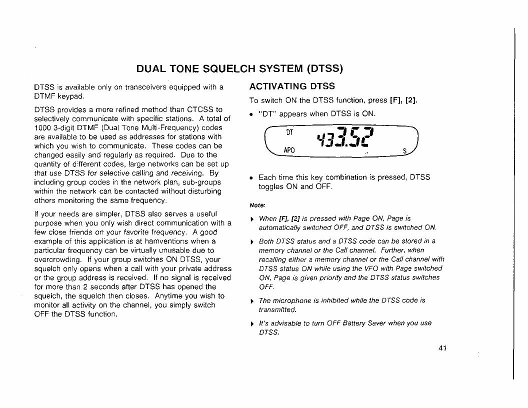
ACTIVATING DTSS . . . . . . . . . . . . . . . . . . . . . . . . . . . . . . . . . .
STORING DTSS CODES . . . . . . . . . . . . . . . . . . . . . . . . . . .
DTSS AND REPEATERS . . . . . . . . . . . . . . . . . . . . . . . . . . .
MEMORY . . . . . . . . . . . . . . . . . . . . . . . . . . . . . . . . . . . . . . . . . . . . . . 32 PAGE . . . . . . . . . . . . . . . . . . . . .. . . ... .. . . .. . . . . . . . . . . . . 43 Making DTMF Calls . . . . . . . . . . . . . . . . . . . . . . . . . . . . . . . . 32
. . . . . . . . . . . . . . . . . . . . . . . . . . . . . . . . . . . . . . . . . . . . OVERVIEW 43 Storing DTMF Numbers . . . . . . . . . . . . . . . . . . . . . . . . . . . 32 PAGE CODE MEMORY . . . . . . . . . . . . . . . . . . . . . . . . . . . . . 43 Confirming Stored DTMF Numbers . . . . . . . . . . . . . 33 STORING PAGE CODES . . . . . . . . . . . . . . . . . . . . . . . . . . 43 Transmitting Stored DTMF Numbers . . . . . . . . . . . 34
. . . . . . . . . . . . . . . . . . . . . . . . . . . . . . . . . . . . . . . . . . . . . . . CALLING 44 Activating DTMF Transmit Hold . . . . . . . . . . . . . . . . . . 34 RECEIVING . . . . . . . . . . . . . . . . . . . . . . . . . . .. . . . . . . . . . . . . . . 45
SCAN . . . . . . . . . . . . . . . . . . . . . . . . . . . . . . . . . . . . . . . . . . . . . . . . . . . 35 Receiving a Call with your Station Code . . . . . . . 45
SCAN RESUME METHODS . . . . . . . . . . . . . . . . . . . . . . .
Time-Operated Scan . . . . . . . . . . . . . . . . . . . . . . . . . . . . . . .
. . . . . . Carrier-Operated Scan . . . . . . . . . . . . . . . . . . . .. SELECTING THE SCAN RESUME METHOD .. MEMORY SCAN . . . . . . . . . . . . . . . . . . . . . . . .... ... . . .
~eceiv ing a Call with a Group Code . . . . . . . . . . . . PAGE CODE AND REPEATERS . . . . . . . . . . . . . . . . . .
LOCKING-OUT CODES . . . . . . . . . . . . . . . . . . . . . . . . . . .
AUTO PAGE CANCEL . . . . . . . . . . . . . . . . . . . . . . . . . . . . . .
OPEN PAGE . . . . . . . . . . . . . . . . . . . . ... . . . . . . . . . . . . . . . .
Locking-Out Memory Channels . . . . . . . . . . . . . . . . . . 37 TONE ALERT . . . . . . . . . . . . . . . . . . . . . . . . . . . . . . . . . . . . . . . . . . . 48 VFO SCAN . . . . . . . . . . . . . . . . . . . . . . .... . . ... . . . . . . . 38 ACTIVATING TONE ALERT . . . . . . . . . . . . . . . . . . . . . . . . 48 CALWFO SCAN . . . . . . . . . . . . . . . . . . . . . . . . . . . . . . . . . . . . 38 CALUMEMORY SCAN . . . . . . . . . . . . . . . . . . . . . . . . . . . . . . 38
REMOTE CONTROL . . . . . . . . . . . . . . . . . . . . . . . . . . . . . . . . . . 49
REMOTE CONTROL USING SMC-33 . . . . . . . . . . . . . . . . . . . . . . . . . . . . . . . . . . . . . . . . . . . OR SMC-34 49
CONNECTING EQUIPMENT FOR REMOTE CONTROL . . . . . . . . . . . . . . . . . . . . . . . . . . . . . . . . . . . . . . . . . . . . . 50
PACKET OPERATION . . . . . . . . . . . . . . . . . . . . . . . . . . . . . . . . 51
MAINTENANCE . . . . . . . . . . . . . . . . . . . . . . . . . . . . . . . . . . . . . . . . 52
GENERAL INFORMATION . . . . . . . . . . . . . . . . . . . . . . . . . 52 SERVICE . . . . . . . . . . . . . . . . . . . . . . . . . . . . . . . . . . . . . . . . . . . . . . 52
. . . . . . . . . . . . . . . . . . . . . . . . . . . . . . . . . . . . . . SERVICE NOTE 53 CLEANING . . . . . . . . . . . . . . . . . . . . . . . . . . . . . . . . . . . . . . . . . . 53
TROUBLESHOOTING . . . . . . . . . . . . . . . . . . . . . . . . . . . . . . . . 54
OPTIONAL ACCESSORIES . . . . . . . . . . . . . . . . . . . . . . . . . 58
INSTALLING OPTIONS . . . . . . . . . . . . . . . . . . . . . . . . . . . . . 60
INSTALLING THE CTCSS UNIT (TSU-8) . . . . . . . 60 INSTALLING THE SPEAKER-MIC JACK STRAIN RELIEF . . . . . . . . . . . . . . . . . . . . . . . . . . . . . . . . . . . . . . 61
. . . . . . . . CONNECTING OPTIONAL EQUIPMENT 62
SPECIFICATIONS . . . . . . . . . . . . . . . . . . . . . . . . . . . . . . . . . . . . . 63
GLOSSARY . . . . . . . . . . . . . . . . . . . . . . . . . . . . . . . . . . . . . . . . . . . . . 64
QUICK REFERENCE GUIDE . . . . . . . . . . . . . . . . . . . . . . . . 71
FEATURES ACCESSORIES
Easier to handle due to the thinner profile, smaller size, and lighter weight. Encourages a "take-it- anywhere" philosophy.
High power output produced from low input voltage means the NiCd battery pack is more compact than previous handhelds.
Innovative Menu Set-up method combines sophisticated features with simple operation; only frequently-used keys are placed on the front and side panels.
ATTENTION! Some transceiver versions are not equipped with a keypad as standard equipment; however, your dealer can install this optional accessory. Functions requiring the keypad cannot be used i f no keypad is installed.
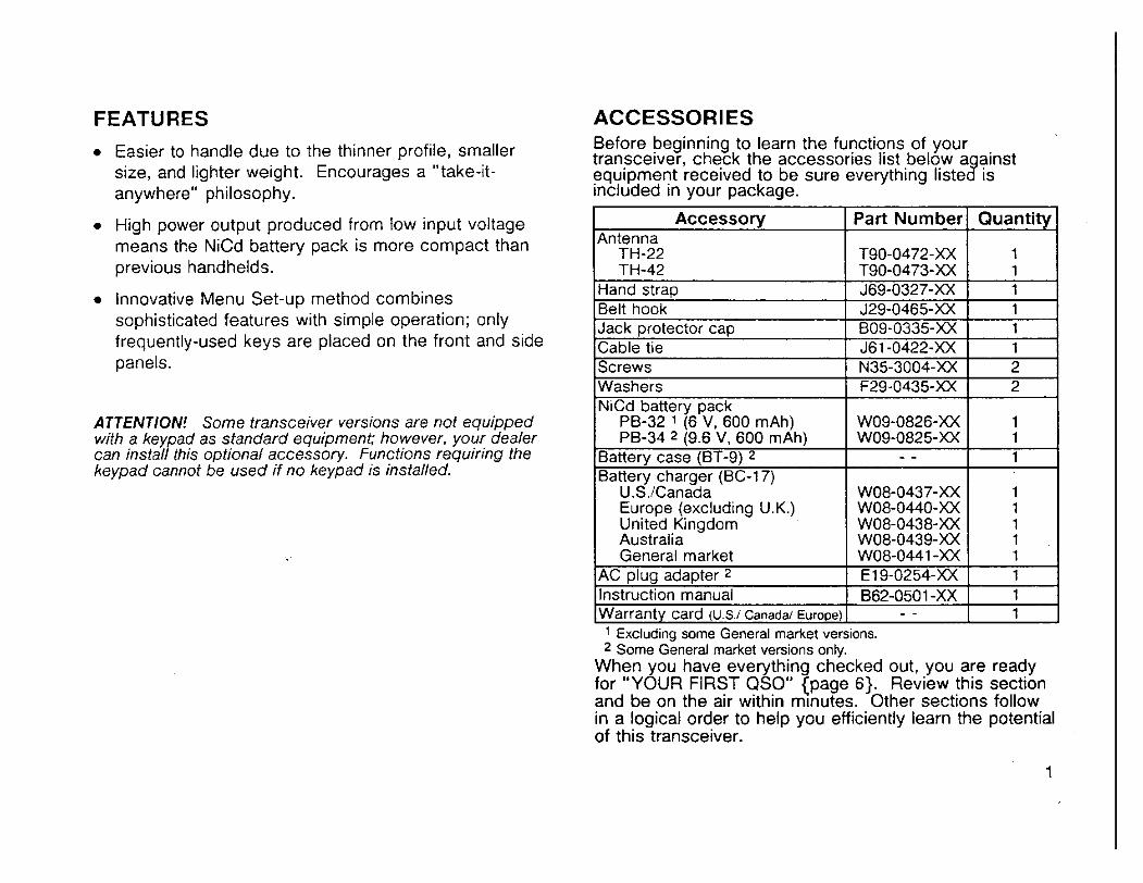
Before beginning to learn the functions of your transceiver, check the accessories list below a ainst equipment received to be sure everything liste IS lncluded In your package.
3, -
Accessory I Part ~ u m b e r l ~ u a n t i t ~ ] Antenna
TH-22 TH-42
Hand strap Belt hook Jack protector cap Cable tie Screws Washers
PB-34 2 (9.6 'v, 600 m ~ h ) I WO9-0825-XX I 1 Batterv case (BT-9) 2 I - - I 1
~~ - . ~. . - -
T90-0472-XX T90-0473-XX J69-0327-XX J29-0465-XX B09-0335-XX J61-0422-XX N35-3004-XX F29-0435-XX
NiCd battery pack PB-32 1 16 V. 600 mAhl
~~ ~ ~~
General market I W08-0441 -XX I 1 AC olua adaoter 2 I E19-0254-XX I 1
1 1 1 1 1 1 2 2
~atter; charg& (BC-I 7)
8- ~- ~
Instruction manual ( 862-0501-XX I 1 Warranty card (U.S.1 Canada/ Europe) 1 - - I 1
WO9-0826-XX
U.S.1Canada Europe (excluding U.K.) United Kingdom Australia
1 Excluding some General market versions. 2 Some General market versions only.
When you have everything checked out, you are ready for "YOUR FIRST QSO" {page 6). Review this section and be on the air within m~nutes. Other sections follow in a logical order to help you efficiently learn the potential of this transceiver.
1
WO8-0437-XX W08-0440-XX W08-0438-XX W08-0439-XX
1 1 1 1

CONVENTIONS FOLLOWED IN THIS MANUAL
The writing conventions described below have been followed to simplify key stroke instructions and avoid unnecessary repetition. This format is less confusing for the reader. Reviewing the following information now will reduce your learning period. That means less time will be spent reading this manual; more time will be available for operating.
Note:
) Basic procedures are numbered sequentially to guide you step-by-step. Additional information pertaining to a step, but not essential to complete the procedure, is provided in bulleted form following many steps for further guidance.
) Most procedures require that you enter a final key stroke that acts as a terminator for the procedure. You can, if you prefer, simply wait for approximately 70 seconds rather than enter this final key entry.
INSTRUCTION
Press [KEY11 + [KEY2].
Press [KEYl] , [KEY2].
Press [KEY] + POWER ON.
Press [Fl (1 s).
Press [KEY1 (1 s)
1 second.
MEANING
Press the keys simultaneously.
Press the keys in sequence.
Press the key while powering the transceiver.
Press the Function key for longer than 1 second.
WHAT TO DO
Press and hold K E Y l down, then press KEY2.
Press KEY1 momentarily, release KEY1, then press KEY2.
With the transceiver power OFF, press and hold KEY, then turn ON the transceiver power.
Press and hold the Function key until the " F" indicator on the display begins
BATTERY INFORMATION
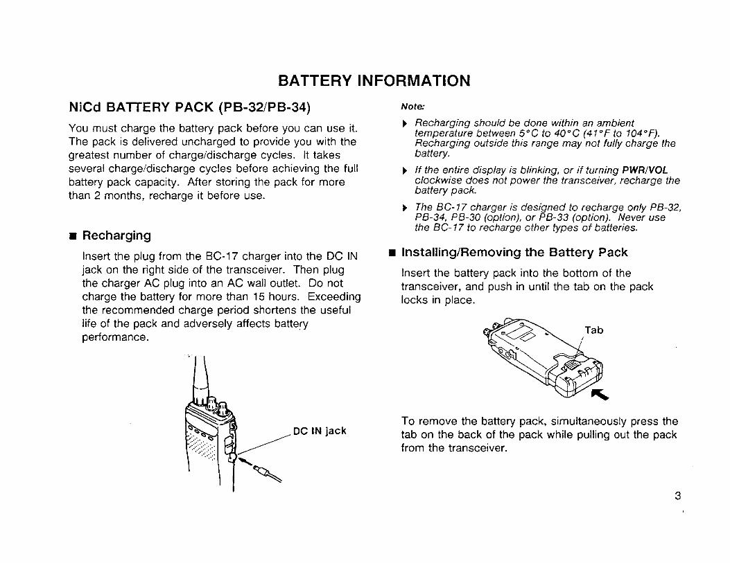
NiCd BAlTERY PACK (PB-32lPB-34)
You must charge the battery pack before you can use it. The pack is delivered uncharged to provide you with the greatest number of chargeldischarge cycles. It takes several chargeidischarge cycles before achieving the full battery pack capacity. After storing the pack for more than 2 months, recharge it before use.
Recharging
Insert the plug from the BC-17 charger into the DC IN jack on the right side of the transceiver. Then plug the charger AC plug into an AC wall outlet. Do not charge the battery for more than 15 hours. Exceeding the recommended charge period shortens the useful life of the pack and adversely affects battery performance.
Note
1 Recharging should be done within an ambient temperature between 5°C to 40°C (47°F to 704°F). Recharging outside this range may not fully charge the battery.
1 If the entire display is blinking, or if turning PWRIVOL clockwise does not power the transceiver, recharge the battery pack.
1 The BC- 77 charger is designed to recharge only PB-32, PB-34, PB-30 (option), or PB-33 (option). Never use the BC- 77 to recharge other types of batteries.
InstallingiRemoving the Battery Pack
Insert the battery pack into the bottom of the transceiver, and push in until the tab on the pack locks in place.
To remove the battery pack, simultaneously press the tab on the back of the pack while pulling out the pack from the transceiver.

INSTALLING/REMOVING MANGANESE OR ALKALINE BAlTERlES (Some General Market Versions)
A fully-charged NiCd battery pack allows optimum performance of your transceiver especially for long transmissions or extended operation. However, when a NiCd battery pack is not available, use high quality alkaline batteries. If manganese batteries are used, it is recommended that transmissions be made only with the " L" or "EL" transmitter output power.
1 To remove the battery case, simultaneously press the tab on the back of the case while pulling out the case from the transceiver.
3 Insert 4 AA manganese or alkaline batteries in the case half with metal contacts making sure the + and - end of each batterv is as shown.
If replacing batteries, remove the old batteries first by lifting up on each battery end. Never discard old batteries in fire as extremely high temperatures can cause batteries to explode.
4 Insert the two small alignment tabs on the other half of the case into their matching holes in the case half containing the batteries. Press the case halves together until the tab on the case bottom locks in place.
the locking tab on the bottom of the case while pulling the two case halves apart.
Note: b Install only alkaline or manganese batteries in the battery case
Installing NiCd batteries in the battery case w~l l cause an electrical shoa that generates heat and damages either the battery case or transceiver.
b Remove the batteries from the battery case if your transceiver will not be used for a long time.
Locking tab

5 Insert the battery case into the bottom of the transceiver, and push in until the tab on the case locks in place.
CAUTION: Do not install the battery pack or batteries in a hazardous environment where sparks could cause an explosion.
BATTERY VOLTAGE LEVEL
The horizontal bars on the Display show the relative battery voltage while transmitting using "EL" output power. Recharge or replace the batteries as necessary using the accompanying diagrams as reference.
BATTERY OPERATING TIME (HOURS)
NiCd Banery (PB-30)
NiCd Banery (PB-32/33)
NiCd Banery (PB-34)
Alkaline Battery
Transmitter Output Power Models Batteries High Low Economic Low
"L" "EL"
6 seconds Transmit, 6 seconds Receive, 48 seconds Standby (AF output 0.2 W ! 8 ohms) Battery Saver ON
New Battery
..I1
e m 1 1 1 1
..l111lll
M ~ I I ~ I
Discharged Battery
.I
M 1 1 1
WWIDIII-
W.
YOUR FIRST QSO
If you tend to discard instruction manuals along with the packaging material ....p lease don't. The 4 steps below will get you on the air in your first QSO within minutes to allow you to experience the exhilaration that comes with opening a brand new transceiver.
After spreading the word to your best buddies that you are now "handy-active", settle back in your most comfortable operating chair with this manual and your favorite drink for an hour or two. The time spent will be worthwhile.
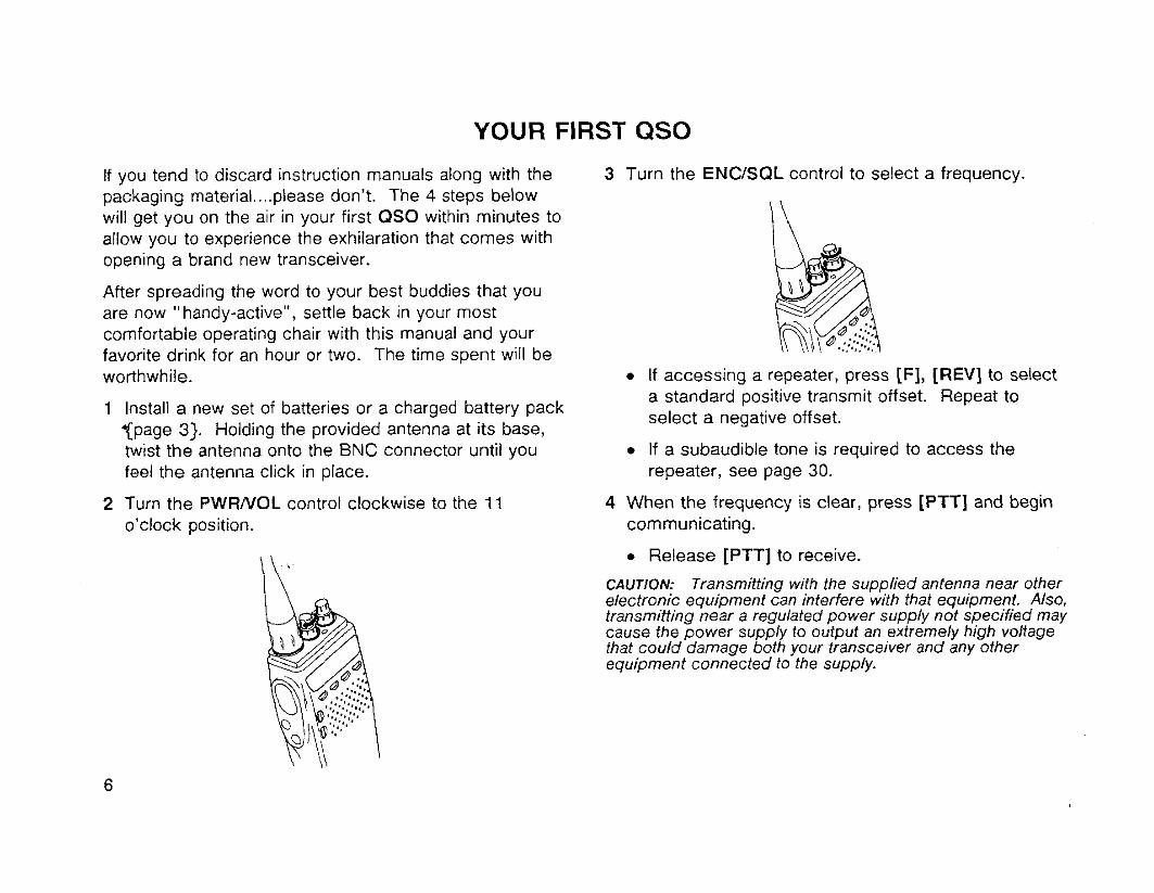
1 Install a new set of batteries or a charged battery pack %page 3). Holding the provided antenna at its base, twist the antenna onto the BNC connector until you feel the antenna click in place.
2 Turn the PWRNOL control clockwise to the 11 o'clock position.
3 Turn the ENCISQL control to select a frequency.
If accessing a repeater, press [F], [REV] to select a standard positive transmit offset. Repeat to select a negative offset.
If a subaudible tone is required to access the repeater, see page 30.
4 When the frequency is clear, press [PTT] and begin communicating.
Release [PTT] to receive.
CAUTION: Transmitting with the supplied antenna near other electronic equipment can interfere with that equipment. Also. transmitting near a regulated power supply not specified may cause the power supply to output an extremely high voltage that could damage both your transceiver and any other equipment connected to the supply.

GETTING ACQUAINTED
ORIENTATION
TH-42AT The keypad is an option for General market versions.
@ PWRNOL @ENC/SQL control control
connector indicator External LED speaker jack
External rnicrophonen iack
External DC IN jack
D TH-42A142E (Keypad optional)
The purpose of the following sections is to describe basic functions. Please refer to later sections for greater detail.
KEYS, CONTROLS, SWITCHES, INDICATORS
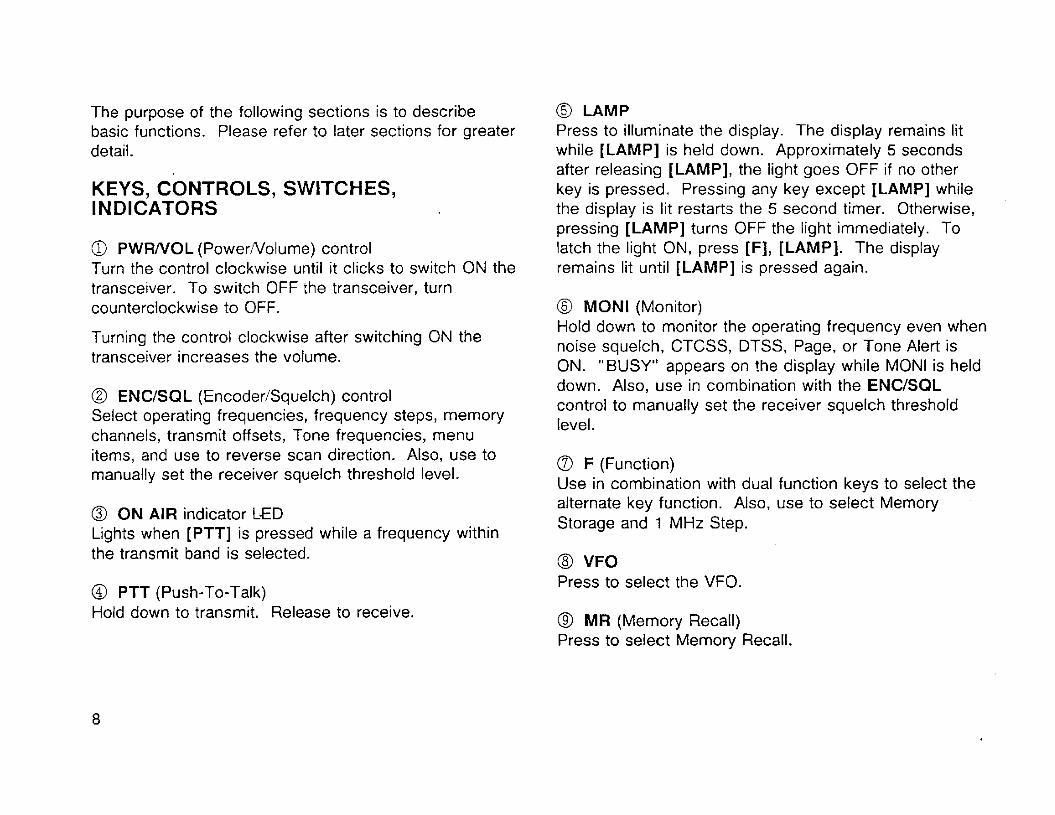
a PWRNOL (PowerNolume) control Turn the control clockwise until it clicks to switch ON the transceiver. To switch OFF the transceiver, turn counterclockwise to OFF.
Turning the control clockwise after switching ON the transceiver increases the volume.
@ ENCISQL (EncoderISquelch) control Select operating frequencies, frequency steps, memory channels, transmit offsets, Tone frequencies, menu items, and use to reverse scan direction. Also, use to manually set the receiver squelch threshold level.
@ O N AIR indicator LED Lights when [PTT] is pressed while a frequency within the transmit band is selected.
@ PTT (Push-To-Talk) Hold down to transmit. Release to receive.
@ LAMP Press to illuminate the display. The display remains lit while [LAMP] is held down. Approximately 5 seconds after releasing [LAMP], the light goes OFF if no other key is pressed. Pressing any key except [LAMP] while the display is lit restarts the 5 second timer. Otherwise, pressing [LAMP] turns OFF the light immediately. To latch the light ON, press [F], [LAMP]. The display remains lit until [LAMP] is pressed again.
@ MONl (Monitor) Hold down to monitor the operating frequency even when noise squelch, CTCSS, DTSS, Page, or Tone Alert is ON. "BUSY" appears on !he display while MONl is held down. Also, use in combination with the ENCISQL control to manually set the receiver squelch threshold level.
a F (Function) Use in combination with dual function keys to select the alternate key function. Also, use to select Memory Storage and 1 MHz Step.
@ VFO Press to select the VFO.
@ MR (Memory Recall) Press to select Memory Recall.
@ CALL Press to recall the Call channel.
@ TICT (ToneICTCSS) Press to switch between Tone and CTCSS functions.
@ REV (Reverse) Press to reverse the transmit and receive frequencies. This is particularly useful when monitoring a repeater to check the signal strength of a station on its transmit frequency.
8 Keypad Use to input numeric data such as frequencies, memory channel numbers, etc. Also, use to input numbers when sending DTMF digits and to control DTSS, Page, and DTMF memory functions.
JACKS AND CONNECTORS
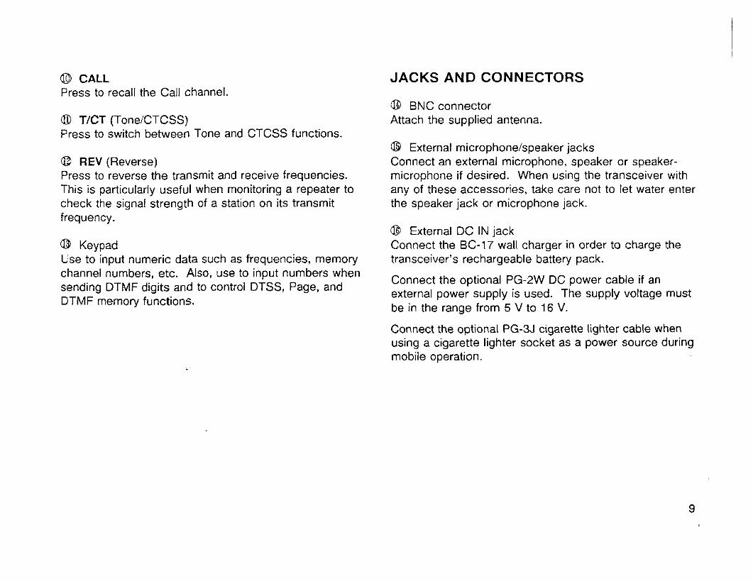
@ BNC connector Attach the supplied antenna.
@ External microphonelspeaker jacks Connect an external microphone, speaker or speaker- microphone if desired. When using the transceiver with any of these accessories, take care not to let water enter the speaker jack or microphone jack.
@ External DC IN jack Connect the BC-17 wall charger in order to charge the transceiver's rechargeable battery pack.
Connect the optional PG-2W DC power cable if an external power supply is used. The supply voltage must be in the range from 5 V to 16 V.
Connect the optional PG-3J cigarette lighter cable when using a cigarette lighter socket as a power source during mobile operation.
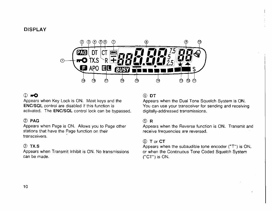
DISPLAY
a d @ DT Appears when Key Lock is ON. Most keys and the Appears when the Dual Tone Squelch System is ON. ENCISQL control are disabled if this function is You can use your transceiver for sending and receiving activated. The ENCISOL control lock can be bypassed. digitally-addressed transmissions.
@ PAG @ R Appears when Page is ON. Allows you to Page other Appears when the Reverse function is ON. Transmit and stations that have the Page function on their receive frequencies are reversed. transceivers.
@ T or CT @ TX.S Appears when the subaudible tone encoder ("T") is ON, Appears when Transmit Inhibit is ON. No transmissions or when the Continuous Tone Coded Squelch System can be made. ("CT") is ON.
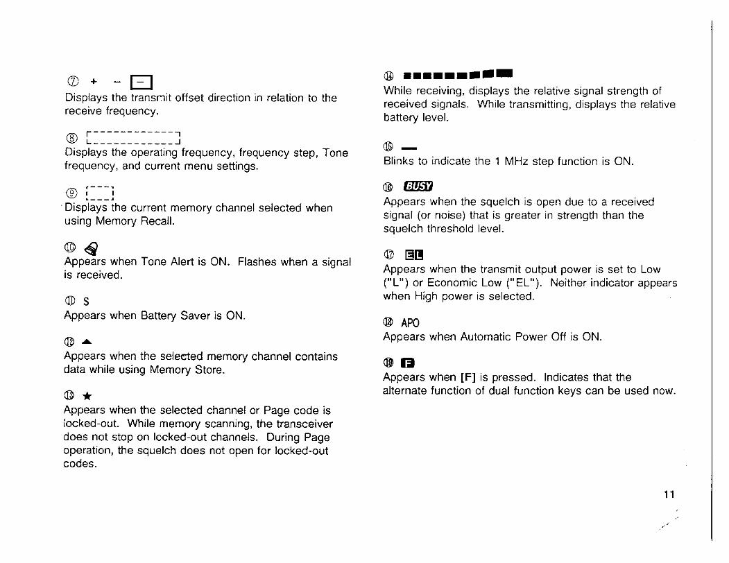
a + -a Displays the transmit offset direction in relation to the receive frequency.
r------------ 1 @ L ------------ _l
Displays the operating frequency, frequency step, Tone frequency, and current menu settings.
,---. 81 . - - - 3 I
Displays the current memory channel selected when using Memory Recall.
@ 4 Appears when Tone Alert is ON. Flashes when a signal is received.
0 s Appears when Battery Saver is ON.
@ A
Appears when the selected memory channel contains data while using Memory Store.
a3 * Appears when the selected channel or Page code is tocked-out. While memory scanning, the transceiver does not stop on locked-out channels. During Page operation, the squelch does not open for locked-out codes.
@ m 1 1 1 1 1 1 1 - While receiving, displays the relative signal strength of received signals. While transmitting, displays the relative battery level.
@ - Blinks to indicate the 1 MHz step function is ON.
@ a m Appears when the squelch is open due to a received signal (or noise) that is greater in strength than the squelch threshold level.
0 Dm Appears when the transmit output power is set to Low ("L") or Economic Low ("EL"). Neither indicator appears when High power is selected.
@ APO Appears when Automatic Power Off is ON.
Appears when [F] is pressed. Indicates that the alternate function of dual function keys can be used now.
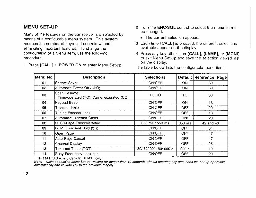
MENU SET-UP 2 Turn the ENCISQL control to select the menu item to be changed.
Many of the features on the transceiver are selected by means of a configurable menu system. This system The current selection appears.
reduces the number of keys and controls without 3 Each time [CALL] is pressed, the different selections eliminating important features. To change the available appear on the display. configuration of a Menu item, use the following 4 Press any key other than [CALL], [LAMP], or [MONI] procedure: to exit Menu Set-UD and save the selection viewed last
on the display. 1 Press [CALL] + POWER ON to enter Menu Set-up.
The table below lists the configurable menu items:
1 05 I~ransmi t Inhibit I ONIOFF I OFF 1 20 I
Menu No.
0 1 02
03
04
1 06 l ~ u n i n a Encoder Lock I ONIOFF 1 OFF I 18 1
Description Battery Saver
Automat~c Power Off (APO)
Scan Resume, Time-operated (TO), Carrrer-operated (CO)
Keypad Beep
1 12 (channel Disolav I ONIOFF I OFF 1 25 I
Selections ONIOFF
ONIOFF
TOICO
ONIOFF
07
08
09 10 11
Note While accessing Menu Set-up, waiting for longer than 10 seconds without entering any data ends the set-up operation automatically and returns you to the previous display.
ON'
350 rns OFF
OFF OFF
, ,
13 (~irne-out Timer (TOT) 1 301 601 901 1801 900 s 1 900 s 1 19
Default ON ON
TO
ON
28 42 and 46
34 47 47
Automatic Transmit Offset DTSSlPage Transmit delay DTMF Transmit Hold (2 s)
Open Page Auto Paoe Cancel
14 1 Busy Frequency Lock-out
Reference Page 39
39
36
18
ONIOFF 350 ms 1 550 ms
ONIOFF
ONIOFF
ONIOFF
ONIOFF I OFF 1 20 1 TH-22AT (U.S.A. and Canada), TH-22E only
RECEIVING
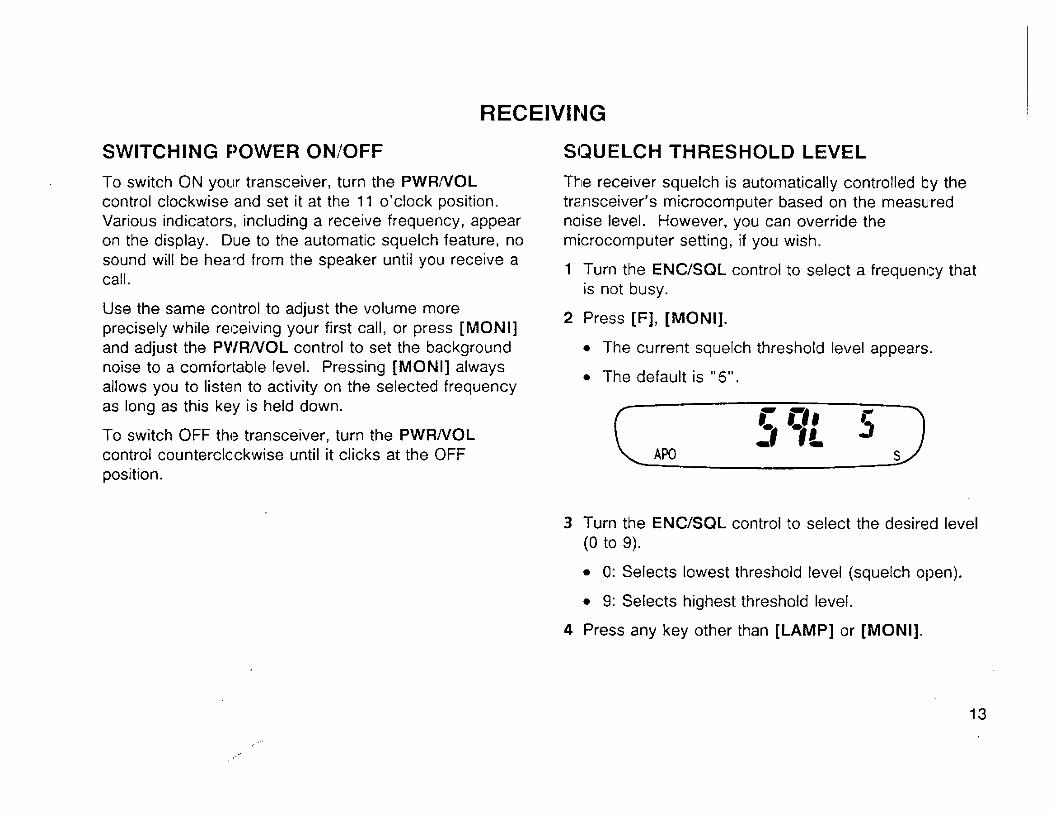
SWITCHING POWER ON/OFF SQUELCH THRESHOLD LEVEL
To switch ON your transceiver, turn the PWRNOL The receiver squelch is automatically controlled by the control clockwise and set it at the 11 o'clock position. transceiver's microcomputer based on the measured Various indicators, including a receive frequency, appear noise level. However, you can override the on the display. Due to the automatic squelch feature, no microcomputer setting, if you wish.
Use the same control to adjust the volume more precisely while receiving your first call, or press [MONI]
2 Press [F], [MONI].
and adjust the PWR/VOL control to set the background The current squelch threshold level appears. noise to a comfortable level. Pressing [MONI] always The default is "5 " . allows you to listen to activity on the sejected frequency as long as this key is held down.
To switch OFF the transceiver, turn the PWRNOL control counterclockwise until it clicks at the OFF position.
3 Turn the ENCISQL control to select the desired level (0 to 9).
0: Selects lowest threshold level (squelch open).
9: Selects highest threshold level.
4 Press any key other than [LAMP] or [MONI].
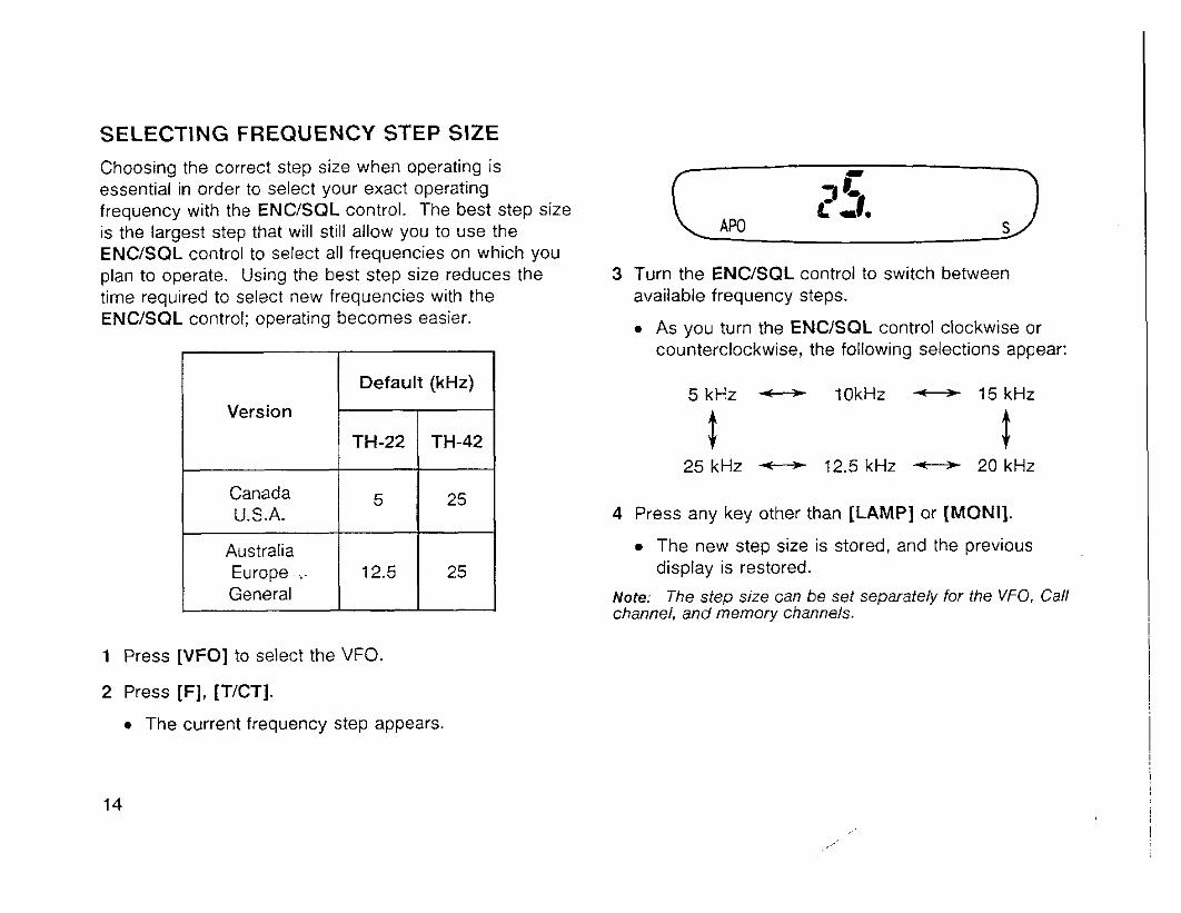
SELECTING FREQUENCY STEP SIZE
Choosing the correct step size when operating is essential in order to select your exact operating frequency with the ENCISQL control. The best step size is the largest step that will still allow you to use the ENCISQL control to select all frequencies on which you plan to operate. Using the best step size reduces the time required to select new frequencies with the ENCISQL control; operating becomes easier.
1 Press [VFO] to select the VFO.
2 Press IF], [TICT].
The current frequency step appears.
Version
Canada U.S.A.
Australia Europe .- General
3 Turn the ENCISQL control to switch between available frequency steps.
As you turn the ENCJSQL control clockwise or counterclockwise, the following selections appear:
Default (kHz) 5 k H z 10kHz - 15kHz
5 t 25 kHz 12.5 kHz 20 kHz
TH-22
5
12.5
4 Press any key other than [LAMP] or [MONI].
TH-42
25
25
The new step size is stored, and the previous display is restored.
Note: The step size can be set separately for the VFO, Call channel, and memory channels.
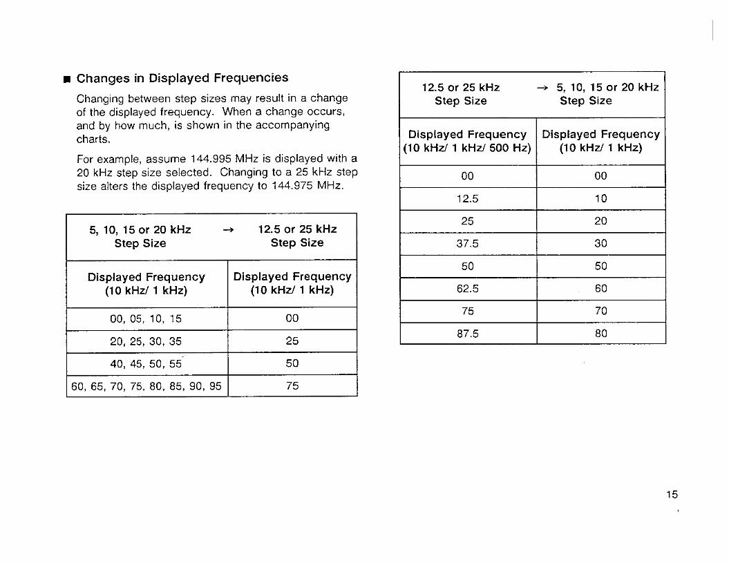
Changes in Displayed Frequencies
Changing between step sizes may result in a change of the displayed frequency. When a change occurs, and by how much, is shown in the accompanying charts.
For example, assume 144.995 MHz is displayed with a 20 kHz step size selected. Changing to a 25 kHz step size alters the displayed frequency to 144.975 MHz.
5, 10, 15 or 20 kHz + 12.5 or 25 kHz Step Size Step Size
12.5 or 25 kHz + 5, 10, 15 or 20 kHz Step Size Step Size
Displayed Frequency (1 0 kHz/ 1 kHz)
- 00, 05, 10, 15
20, 25, 30, 35
40, 45, 50, 55'
60, 65, 70, 75, 80, 85, 90, 95
Displayed Frequency (10 kHz/ 1 kHz/ 500 Hz)
00
12.5
25
37.5
50
62.5
75
87.5
Displayed Frequency (1 0 kHz/ 1 kHz)
00
25
50
75
Displayed Frequency (1 0 kHz/ 1 kHz)
00
10
20
30
50
60
70
80 -
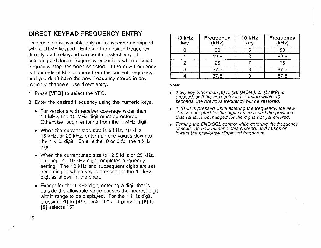
DIRECT KEYPAD FREQUENCY ENTRY
This function is available only on transceivers equipped with a DTMF keypad. Entering the desired frequency directly via the keypad can be the fastest way of selecting a different frequency especially when a small frequency step has been selected. If the new frequency is hundreds of kHz or more from the current frequency, and you don't have the new frequency stored in any memory channels, use direct entry.
1 Press [VFO] to select the VFO.
2 Enter the desired frequency using the numeric keys.
For versions with receiver coverage wider than 10 MHz, the 10 MHz digit must be entered. Otherwise, begin entering from the 1 MHz digit.
e When the current step size is 5 kHz, 10 kHz, 15 kHz, or 20 kHz, enter numeric values down to the 1 kHz digit. Enter either 0 or 5 for the 1 kHz digit.
When the current .step size is 12.5 kHz or 25 kHz, entering the 10 kHz digit completes frequency setting. The 10 kHz and subsequent digits are set according to which key is pressed for the 10 kHz digit as shown in the chart.
Except for the 1 kHz digit, entering a digit that is outside the allowable range causes the nearest digit within ranae to be dis~laved. For the 1 kHz diait.
Note:
r If any key other than 101 to 191, [MONI], or [LAMP] is pressed, or if the next entry is not made within 10 seconds, the previous frequency will be restored.
r If WFO] is pressed while entering the frequency, the new data is accepted for fhe digits entered and the previous data remains unchanged for the digifs not yet entered.
r Turning the ENCISQL control while entering the frequency cancels the new numeric data entered, and raises or lowers the previously displayed frequency.
pressing B] to [4] seiecis "0" and pressing [3 to [9] selects "5".
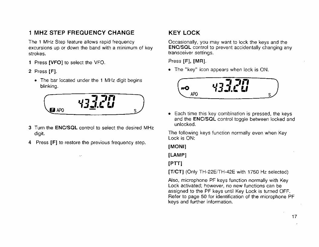
1 MHZ STEP FREQUENCY CHANGE
The 1 MHz Step feature allows rapid frequency excursions up or down the band with a minimum of key strokes.
1 Press [VFO] to select the VFO.
2 Press IF].
The bar located under the 1 MHz digit begins blinking.
3 Turn the ENCISQL control to select the desired MHz digit.
4 Press [F] to restore the previous frequency step.
KEY LOCK
Occasionally, you may want to lock the keys and the ENCISQL control to prevent accidentally changing any transceiver settings.
Press [F], [MR].
The "key" icon appears when lock is ON.
Each time this key combination is pressed, the keys and the ENCISQL control toggle between locked and unlocked.
The following keys function normally even when Key Lock is ON:
[MONI]
[LAMP]
[PTTI
[TICT] (Only TH-22ETTH-42E with 1750 Hz selected)
Also, microphone PF keys function normally with Key Lock activated; however, no new functions can be assigned to the PF keys until Key Lock is turned OFF. Refer to page 50 for identification of the microphone PF keys and further information.

UNLOCKING ENCISQL CONTROL
If you only want to lock the keys but not the ENCISQL control when Key Lock is activated, that is possible too.
1 Press [CALL] + POWER ON to select Menu Set-up.
2 Turn the ENCISQL control to select Menu No. 06.
The current status of ENCJSQL control lock appears.
The default is "OFF".
3 Press [CALL] to select "ON" or "OFF".
OFF: Locks ENCISQL control with keys.
ON : Does not lock ENCJSQL control with keys.
4 Press any key other than [CALL], [LAMP], or [MONI] to exit Menu Set-up.
BEEP TONE ON/OFF I The transceiver beeps each time you press a key on the transceiver with the exception of [MONI], [LAMP], and [PTT]. Pressing [PTT] generates a beep if your transmit frequency is outside the transmit band. Beep volume can be varied by turning the PWRNOL control. I
If you prefer, you can cancel the beep for silent operation.
1 Press [CALL] + POWER ON to enter Menu Set-up.
2 Turn the ENCJSQL control to select Menu No. 04.
The current beep status appears.
The default is "ON".
3 Press [CALL] to select "OFF" or "ON"
OFF: Disables Keypad Beep.
ON : Enables Keypad Beep.
4 Press any key other than [CALL], [LAMP], or [MONI] to exit Menu Set-up.
Note When Tone Alert is switched ON while the Beep function is OFF, an audible alarm does not sound when a signal is received.
TRANSMITTING
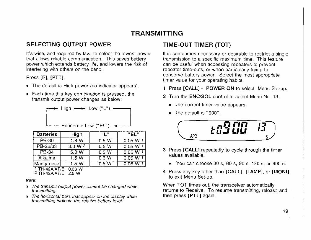
SELECTING OUTPUT POWER TIME-OUT TIMER (TOT)
It's wise, and required by law, to select the lowest power that allows reliable comrnunicatjon. This saves battery power which extends battery life, and lowers the risk of interfering with others on the band.
Press [F], [PTTJ.
The default is High power (no indicator appears).
Each time this key combination is pressed, the transmit output power changes as below:
High + Low ("L") 1 Economic Low ("EL") 1
b The transmif oufput power cannot be changed while tran srnitting.
Batteries PB-30
L
b The horizontal bars fhat appear on the display while transmitting indicate the relative battery level.
I' L"
0.5 W High 1.8 W
PB-34 Alkaline
Manganese
It is sometimes necessary or desirable to restrict a single transmission to a specific maximum time. This feature can be useful when accessing repeaters to prevent repeater time-outs, or when particularly trying to conserve battery power. Select the most appropriate timer value for your operating habits.
"EL" 0.05 W 1
PB-32/33 1 3.0 W 2 1 0.5 W
1 Press [CALL] + POWER ON to select Menu Set-up.
0.05 W 1
1 TH-42NAT/E: 0.03 W
5.0-W 1.5 W 1.5 W
2 Turn the ENC/SQL control to select Menu No. 13.
The current timer value appears.
+ The default is " 900".
0.5 W 0.5 W 0.5 W
3 Press [CALL] repeatedly to cycle through the timer values available.
0.05 W ' 0.05 W 1
0.05 W 1 You can choose 30 s, 60 s, 90 s, 180 s, or 900 s.
4 Press any key other than [CALL], [LAMP], or [MONI] to exit Menu Set-up.
When TOT times out, the transceiver automatically returns to Receive. To resume transmitting, release and then press [PTT] again.

INHIBITING THE TRANSMITTER
The transmit function can be disabled to prevent unauthorized individuals from transmitting, or to eliminate the risk of yourself accidentally transmitting.
1 Press [CALL] + POWER ON to select Menu Set-up.
2 Turn the ENC/SQL control to select Menu No. 05.
The current Transmit Inhibit status appears.
The default is "OFF".
- i i j P i nr 4, r, h ~ U 0 * 0 *
APO S
3 Press [CALL] to select "OFF" or "ON".
OFF: Enables transmitter ("TX.S" disappears).
ON : Inhibits transmitter ... ("TX.S" appears).
4 Press any key other than [CALL], [LAMP], or [MONI] to exit Menu Set-up.
If [PTT] is pressed while Transmit lnhibit is ON, your transceiver beeps and will not transmit. The PTT switch on any microphone configured for remote control with this transceiver also will be disabled. On TH-22G'TH-42E versions, the 1750 Hz tone cannot be transmitted while Transmit Inhibit is activated.
BUSY FREQUENCY LOCK-OUT
A method of inhibiting the transmitter when the current receive frequency is busy. is provided. This feature can help to eliminate "doubling" (simultaneous transmissions) with other stations.
1 Press [CALL] + POWER ON to enter Menu Set-up.
2 Turn the ENC/SQL control to select Menu No. 14.
The current Busy Frequency Lock-out status appears.
The default is "OFF".
3 Press [CALL] to select "OFF" or "ON".
OFF: Enables transmitter on a busy frequency.
ON : Inhibits transmitter on a busy frequency.
4 Press any key other than [CALL], [LAMP], or [MONI] to exit Menu Set-up.

MEMORY CHANNELS
A total of 40 memory channels (0 to 39) are available for STORING DATA IN MEMORY storing frequencies and related data. Each memory There are 2 methods of storing transmitireceive channel can be used either as a simplex channel or split frequencies and associated data in memory channels channel. Alternatively, a standard or non-standard depending on the relationship of the transmit and receive frequency offset and offset direction required for using frequencies: reoeaters can be stored. Refer to "OPERATING THROUGH REPEATERS" {page 27).
The data listed below can be stored in each memory channel:
Simplex memory channels: RX frequency = TX frequency
Split memory channels: RX frequency # TX frequency
Simplex Memory Channels
1 Select the desired frequency and associated data (Tone, CTCSS, DTSS, etc.) using the VFO, Memory Recall or the Call channel.
2 Press [F] (1 s) to select Memory Storage.
3 Select the desired memory channel using the ENCiSQL control.
YES: Can be stored in memory N/A : Not applicable

4 Press [MR]. Split Memory Channels
The selected frequency and associated data are stored in the memory channel.
If the memory channel selected in the previous step already contained data, the new data overwrites the previous data.
The previous mode is restored.
The " A " symbol under the channel number indicates the following:
Symbol ON : Channel contains data.
Symbol blinking : Channel empty.
7 4 i - 1 r 7 r 1 r 1 3 - 7 ~ J . x u7 A
APO s
1 After storing the receive frequency using "Simplex memory channels" instructions in the preceding section, select the desired transmit frequency.
2 Press IF] (1 s) to select Memory Storage.
3 Turn the ENCISQL control to select the memory channel containing the receive frequency.
4 Press [PTT] + [MR].
The selected transmit frequency is stored in the memory channel, and the previous mode is restored.
If the memory channel selected does not contain a receive frequency, your transceiver beeps and restores the previous mode.
Associated data such as Tone statuslfrequency, frequency step, and DTSS status/code are not overwritten. However, transmit shift status and Reverse status data are erased.
RECALLING MEMORY CHANNELS
Using the ENCISQL Control
1 Press [MR].
The memory channel used last is recalled.
If all memory channels are empty, your transceiver beeps and Memory Recall is not selected.
2 Turn the ENCISQL control to select the desired memory channel.
Clockwise : Increases the channel number.
Counterclockwise : Decreases the channel number.
Empty memory channels cannot be recalled.
Using the Keypad
1 Press [MR].
The memory channel used last is recalled.
2 Enter a 2-digit number (00 to 39) to select the desired memory channel.
Empty memory channels cannot be recalled.
MEMORY + VFO TRANSFERS
Transferring the contents of a memory channel or the Call channel to the VFO can be useful if you wish to search for other stations or a clear frequency near the selected memory channel or Call channel frequency. This is a quick operation that will be used frequently, especially if you enjoy exploring the band.
1 Press [MR] to select Memory Recall, or [CALL] to select the Call channel.
2 Recall the desired memory channel using the ENCfSQL control.
This step is not necessary if the Call channel was selected.
3 Press [F], [VFO].
The complete contents of the memory channel or the Call channel are copied to the VFO.
A transmit frequency from a split memory channel or split Call channel is not transferred to the VFO.
Note: When a split memory channel is recalled, "? " appears on the display to the left of the receive frequency. Press [REV] to display the transmit frequency.

ERASING MEMORY CHANNELS
Although it is possible to overwrite existing data in any of the memory channels with new data, at times you may wish to clear data from memory channels without entering new data. It's convenient to clear channels no longer used so you can identify channels that are free for memorizing new frequencies.
1 Press [MR] to select Memory Recall.
2 Select the desired memory channel using the ENClSQL control or numeric keys.
3 Switch OFF the power.
4 Press [MR] + POWER ON.
The contents of the memory channel are erased and transferred to the VFO. The VFO is selected.
CALL CHANNEL
The Call channel can be used to store any frequency within your transceiver operating range that you wish to make your main operating frequency. No matter what mode the transceiver is in, the Call channel always can be selected quickly. You may wish to dedicate the Call channel on a group-wide basis as an emergency channel only to be used for urgent communications. In this case, Call Scan {page 38) will be useful.
Recalling Call Channel
Press [CALL] to retrieve the contents of the Call channel.
If [CALL] is pressed again, the rev id us mode is restored.
The ENClSQL control does not function while the Call channel is selected.
The Call channel defaults are as follows:
Version
Canada U.S.A.
Australia Europe General
Default (MHz)
TH-22
144.000
144.000
TH-42
440.000
430.000
The contents of the Call channel cannot be deleted; however, you can overwrite old data with new data as described below.
Changing Call Channel Contents (Simplex)
1 Select the desired frequency and associated data (Tone, CTCSS, DTSS, etc.) using the VFO or Memory Recall.
2 Press [F] (1 s) to select Memory Storage.
3 Press [CALL].
The selected frequency and associated data are stored in the Call channel, and the previous mode is restored.
Changing Call Channel Contents (Split)
1 After storing the receive frequency using "Changing Call channel contents (Simplex)" instructions in the preceding section, select the desired transmit frequency.
2 Press [F] (1 s) to select Memory Storage.
3 Press [PTT] + [CALL].
The selected transmit frequency is stored in the Call channel, and the previous mode is restored.
CHANNEL DISPLAY FUNCTION 'I
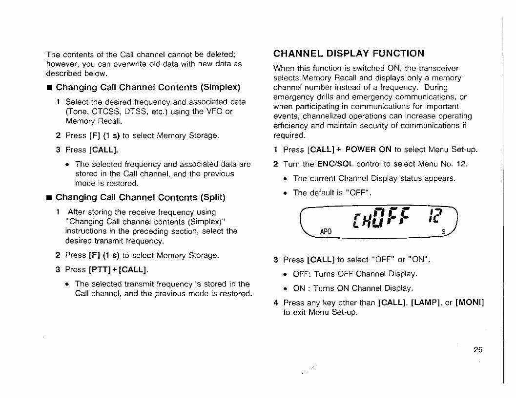
When this function is switched ON, the transceiver selects Memory Recall and displays only a memory channel number instead of a frequency. During emergency drills and emergency communications, or when participating in communications for important events, channelized operations can increase operating efficiency and maintain security of communications if required.
1 Press [CALL] + POWER ON to select Menu Set-up.
2 Turn the ENCISQL control to select Menu No. 12.
The current Channel Display status appears.
The default is "OFF".
3 Press [CALL] to select "OFF" or "ON".
OFF: Turns OFF Channel Display.
ON : Turns ON Channel Display.
4 Press any key other than [CALL], [LAMP], or [MOMI] to exit Menu Set-up.
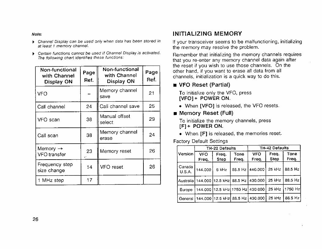
Note: INITIALIZING MEMORY ) Channel Display can be used only when data has been stored in If your transceiver seems to be malfunctioning, initializing
at least r memory channel. the memorv mav resolve the problem. ) Certain functions cannot be used if Channel Display is activated.
The follow~ng chart identifies these functions: Remember that initializing the memory channels requires that you re-enter any memory channel data again after the reset if you wish to use those channels. On the other hand, if you want to erase all data from all channels, initialization is a quick way to do this.
Frequency step size change
1 MHz step
VFO Reset (Partial) To initialize only the VFO, press [VFO] + POWER ON.
When [VFO] is released, the VFO resets.
Memory Reset (Full) To initialize the memory channels, press [F] + POWER ON.
When [F] is released, the memories reset.
Factory Default Settings
14
17
I ~144.000 1 5 kHz 1 88.5 Hz I440000 1 25 kHz 1 88.5 Hz / VFO reset
l~ustralial 144.000 112.5 k ~ z l 88.5 Hz 1430.000 1 25 kHz / 88.5 H Z I
Version
26
TH-42 Defaults TH-22iefaults
Europe
Tone Freq.
VFO Freq.
VFO Freq.
General
Freq. Step
144.000
Freq. Step
144.000
Tone Freq.
12.5 kHz
12.5 kHz
1750 Hz
88.5 Hz
430.000
430.000
25 kHz 1750 Hz
25 kHz 88.5 Hz

OPERATING THROUGH REPEATERS
TRANSMllTER OFFSETS SELECTING OFFSET DIRECTION I All Amateur Radio voice repeaters use a separate receive and transmit frequency. The transmit frequency may be higher or lower than the receive frequency but the difference in frequencies will be a standard amount, or "standard split". Most repeater configurations fall into one of the following categories:
This function sets the transmit frequency either higher ( + ) or lower ( - ) than the receive frequency by a fixed amount. Refer to "Selecting Offset Values Manually" {page 29) if you want to change the offset amount.
Offset Direction
Press [F], [REV].
The default is "simplex" (no offset). I TH-22A/AT/E
Each time this key combination is pressed, the offset changes as follows:
i
Simplex* + t - t-, Simplex-, + t - t - i
TH-4WAT
If the offset transmit frequency falls outside the transmit band, transmit is inhibited until the transmit frequency is brought within the band by one or more of the following methods:
TH-42E
Move the receive frequency further inside the band. Whether using the VFO, Memory Recall, or the Call channel, the transmit offset direction and amount can be Reduce the offset amount ("Selecting Offsets
changed. Manually" {page 29)).
Reverse the offset direction.
AUTOMATIC TRANSMIT OFFSET
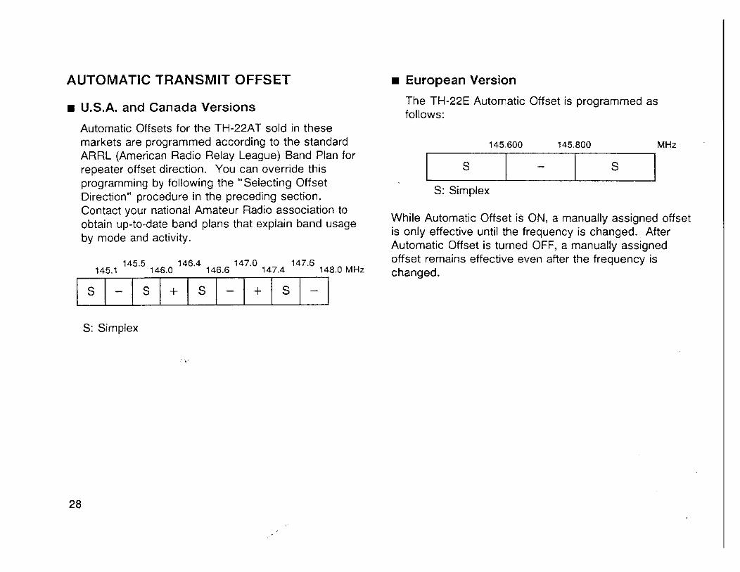
U.S.A. and Canada Versions
Automatic Offsets for the TH-22AT sold in these markets are programmed according to the standard ARRL (American Radio Relay League) Band Plan for repeater offset direction. You can override this programming by following the "Selecting Offset Direction" procedure in the preceding section. Contact your national Amateur Radio association to obtain up-to-date band plans that explain band usage by mode and activity.
145.5 146.4 147.0 147.6 145.1 146.0 146.6 147.4 148.0 MHz
S: Simplex
. -
European Version
The TH-22E Automatic Offset is programmed as follows:
145.600 145.800 MHz
S: Simplex
While Automatic Offset is ON, a manually assigned offset is only effective until the frequency is changed. After Automatic Offset is turned OFF, a manually assigned offset remains effective even after the frequency is changed.

Canceling Automatic Offset
Automatic Offset can be canceled as described below:
1 Press [CALL] + POWER ON to enter Menu Set-up.
2 Turn the ENCISQL control to select Menu No. 07.
The current Automatic Offset status appears.
The default is "ON" for TH-22 versions sold in the U.S.A., Canada and Europe.
3 Press [CALL] to select "OFF" or "ON".
OFF: Cancels Automatic Offset.
ON : Restores Automatic Offset.
4 Press any key other than [CALL], [LAMP], or [MONI] to exit Menu Set-up.
SELECTING OFFSET VALUES MANUALLY
To change the amount of offset, use the following procedure:
1 Press IF] (1 s), [REV].
2 Turn the ENCISQL control to select the desired value.
The values range from 0.00 MHz to 99.95 MHz in 50 kHz steps.
3 Press any key other than [MONI] or [LAMP] to store the selected value.
The previous mode is restored.
Remember the following points before altering the offset:
The TH-42E offset can be changed from the default 1.6 MHz value; however, the 7.6 MHz value is not configurable.
It is not possible to set different offset values for the VFO and memory channels.
The new manually selected value will be used even if Automatic Offset is switched ON.
Note After turning ON Automatic Offset again, or afler transferring memory channel contents to the VFO, the feature resumes functioning when a new frequency is selected.

REVERSE FUNCTION
Each time [REV] is pressed, the receive frequency is switched with the transmit frequency. When used while monitoring a repeater, it's possible to check the signal strength of a station accessing the repeater. If the station's signal is strong, it's best to move to a simplex frequency to continue the contact and free-up the repeater.
If reversal would place the receive frequency outside the receiver frequency range, an error beep sounds when [REV] is pressed. No reversal occurs.
If the transmit frequency would go out of the transmitter frequency range if [PTT] were pressed, then pressing [PTT] causes an error beep and Receive is selected.
Reverse cannot be activated while [PTT] is held down.
Automatic Offset cannot be used while Reverse is ON.
TONE ACCESS
Each time [TtCT] is pressed, the Tone and CTCSS functions are changed as follows:
No indicator - T - CT
No indicator : Subaudible tone not transmitted and tone squelch not functional.
T : Subaudible tone transmitted.
CT : Subaudible tone transmitted and tone squelch functional.
Note:
) "CT" will appear if [TICTI is pressed when the TSU-8 CTCSS module is not installed: however, CTCSS will not function.
TH-22EiTH-42E only
) When fl/CT] is pressed with 1750 Hz selected, 1750 Hz tones are transmitted. "T" appears during this period. Releasing [TICTI stops transmission and "T" goes OFF.
) If WCT] is pressed when any frequency other than 1750 Hz is selected, Tone will switch ON and OFF,
) When 1750 Hz is selected while Tone is OFF, pressing mCT] does not change the TonelCTCSS status. When 1750 Hz is selected while Tone or CTCSS is ON, 'T' or "CT" goes OFF.

Often a Tone frequency is required to access repeaters. For example, 88.5 Hz may be needed in the U.S.A. or Canada, and 1750 Hz is used in Europe. The Tone frequencies listed below can be selected. On the TH-22E/TH-42E. 1750 Hz also can be selected.
The following procedure allows you to select any of the available tones.
1 Press [F] (1 s), [TICT].
2 Turn the ENCISQL control to select the desired Tone frequency.
AUTOPATCH (U.S.A. and Canada Versions)
Some repeaters offer a service called Autopatch. This feature allows you to dial a telephone number from your transceiver and carry on a telephone conversation. This repeater function cannot be used for commercial transactions, but it can save lives when used appropriately during emergencies.
Autopatch requires the use of a DTMF (Dual Tone Multi- Frequency) keypad. The keypad includes the 12 keys found on your telephone plus an additional 4 keys (A, B, C, D). These additional keys are required for various control operations by some repeater systems.
Activating the Keypad
1 Press and hold [PTT].
2 Press keys in sequence to transmit tones.
To generate single-frequency tones for test purposes, press [MONI] before pressing a single key from [1 ] to [8 ] .
3 Press any key other than [MONI] or [LAMP] to store the selected value.

DTMF Tones
Single-Frequency Tones r I 11 I 1
Freq. Freq.
Note. Some repeaters'require a special key sequence to activate Autopatch. Check with the control operator.
DUAL TONE MULTI-FREQUENCY (DTMF) MEMORY
This function is available only on transceivers equipped with a DTMF keypad.
Making DTMF Calls
To make a DTMF call, hold down [PTT] and press [0] to 191, [A], [Bl, [Cl, [Dl, [*I, or [#I.
The microphone is muted and the corresponding DTMF tones are transmitted. You can monitor the tones as they are sent by listening to the speaker audio.
If two keys are pressed, only the tone combination for the key pressed first is sent.
Storing DTMF Numbers
To store a DTMF number in dedicated DTMF memory channels 1 to 5, follow the procedure below:
1 Press [F] (1 s), [3] to select DTMF Storage.
r 7 - - - r APO

2 Enter the desired DTMF digits using the keypad (15 digits maximum).
If incorrect data is entered, press [VFO] and enter the correct data from the beginning.
To abort data entry, press [CALL]. The previous mode is restored.
3 Press [MR], [ I ] to [5].
Only press a single number corresponding to the desired DTMF memory channel.
The previous mode is restored.
Confirming Stored DTMF Numbers
1 Press [F], [3].
The following display appears:
APO P-
2 Enter the DTMF memory channel (1 to 5) that contains the DTMF number.
The stored DTMF digits are displayed.
Selecting a DTMF memory channel that has no DTMF number stored causes the previous display to be restored.
1 Transmitting Stored DTMF Numbers
To transmit a stored DTMF number, use the following procedure:
1 Press [PTT] + [CALL] and continue holding [PTT] down.
The following display appears:
p- APO mmmmmm
2 Enter the DTMF memory channel (1 to 5 ) that contains the DTMF number to be transmitted.
The stored DTMF digits are displayed as they are transmitted.
Transmission continues until all digits are sent. Releasing [PTT] will not interrupt the digits being sent or stop transmission.
Selecting a DTMF memory channel that has no DTMF number stored causes the previous display to be restored.
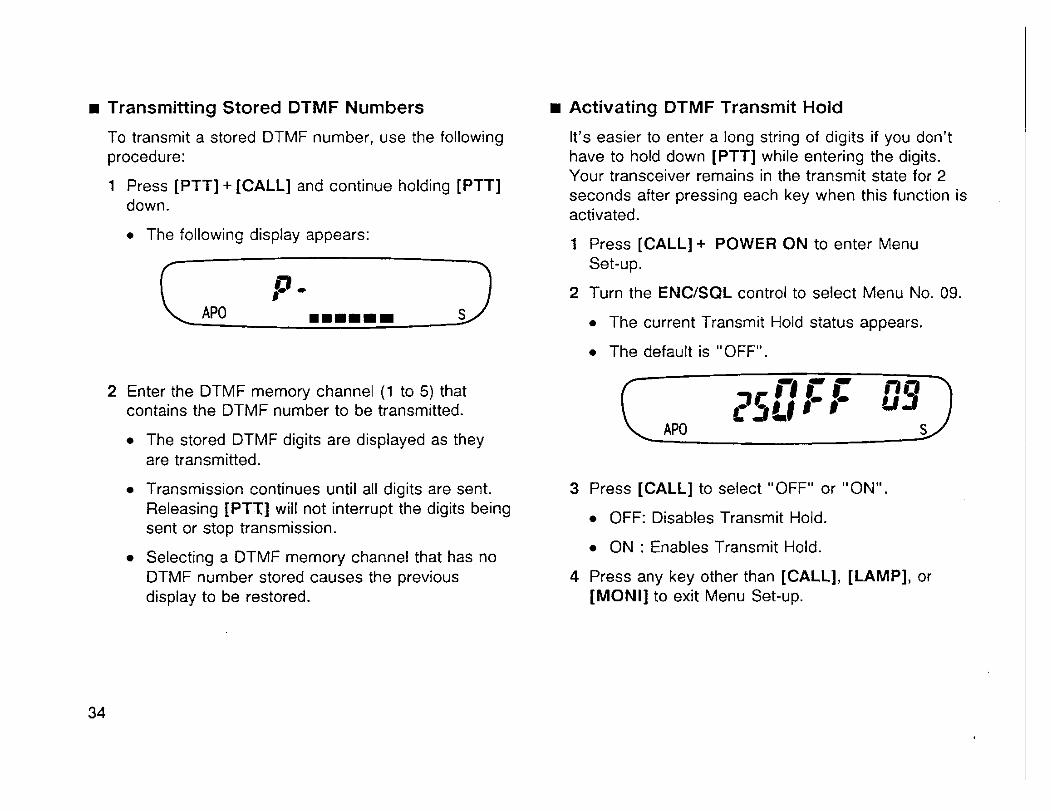
1 Activating DTMF Transmit Hold
It's easier to enter a long string of digits if you don't have to hold down [PTT] while entering the digits. Your transceiver remains in the transmit state for 2 seconds after pressing each key when this function is activated.
1 Press [CALL] + POWER ON to enter Menu Set-up.
2 Turn the ENC/SQL control to select Menu No. 09.
The current Transmit Hold status appears.
The default is "OFF".
3 Press [CALL] to select "OFF" or "ON".
OFF: Disables Transmit Hold.
ON : Enables Transmit Hold.
4 Press any key other than [CALL], [LAMP], or [MONI] to exit Menu Set-up.

Scan is a useful feature for hands-off monitor in^ of vour Notc - favorite frequencies. After becoming comfortable with > If Page or Tone Alert is ON, Scan will not function. how to use all 4 types of scan, the monitoring flexibility gained will increase your operating efficiency. > For CTCSS operation, Scan stops and the squelch opens
only for signals that contain the same CTCSS tone that is
The 4 types of scan are as follows:
If PF keys on a microphone being used for remote control of your transceiver are assigned the UPIDOWN functions, scan direction can be reversed using these PF keys. Refer to page 50 for identification of the microphone PF keys and further information.
Scan Type
Scan
VFO Scan
CallNF0 Scan
Call/Memory Scan
stored in your transceiver.
Purpose
Quick Activity update of your favorite frequencies.
General update on band activity.
Monitor the Call channel plus any VFO frequency.
Monitor the Call channel plus your favorite frequency.
> For DTSS operation, Scan stops for any signal received; however, the squelch opens only for signals that contain the same DTSS code that is stored in your transceiver.
) When both CTCSS and DTSS are ON, Scan stops for signals that contain the matching CTCSS tone. However, the squelch opens only when the matching DTSS code is received.

SCAN RESUME METHODS
When using Scan, it's necessary to decide under what condition you want your transceiver to continue scanning after detecting and stopping for a signal. You can choose Time-operated Scan or Carrier-operated Scan. The default is Time-operated Scan.
H Time-Operated Scan
Your transceiver stops scanning after detecting a signal, remains there for approximately 5 seconds, and then continues to scan even if the signal is still present.
H Carrier-Operated Scan Your transceiver stops scanning after detecting a signal and remains on the same frequency until the signal drops out. There is a 2 second delay between signal drop-out and scan resumption to allow time for any responding stations to begin transmitting.
SELECTING THE SCAN RESUME METHOD
Use the following procedure to switch your transceiver between Time-operated Scan and Carrier-operated Scan.
1 Press [CALL] + POWER ON to enter Menu Set-up.
2 Turn the ENCJSQL control to select Menu No. 03.
The current Scan Resume status appears.
The default is "TO" (time-operated scan).
3 Press [CALL] to select either "TO" or "CO"
4 Press any key other than [CALL], [LAMP], or [MONI] to exit Menu Set-up.
Note: Holding [MONI] down while scanning halts Scan regardless whether Time-operated or Carrier-operated Scan is selected. Resume scanning by releasing [MONI].
MEMORY SCAN
Memory Scan allows all memory channels containing data to be scanned.
1 Press [MR] (1 s).
Scan starts with the channel last recalled, then ascends up through the memory channels.
2 To reverse the scan direction and scan down through the memory channels, turn the ENCISQL control counterclockwise.
Upward scan : Turn ENClSQL clockwise.
Downward scan: Turn ENCISQL counterclockwise.
3 To cancel Memory Scan, press any key other than [MONI] or [LAMP].
At least 2 memory channels must contain data for Scan to function. Also, at least 2 memory channels must not be locked-out.
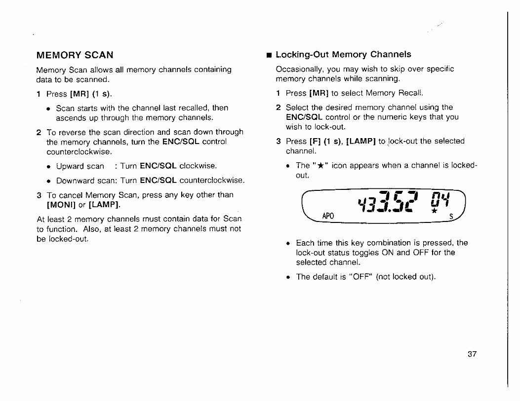
Locking-Out Memory Channels
Occasionally, you may wish to skip over specific memory channels while scanning.
1 Press [MR] to select Memory Recall.
2 Select the desired memory channel using the ENCISQL control or the numeric keys that you wish to lock-out.
3 Press [F] (1 s), [LAMP] to ~. jock-out the selected channel.
The "+" icon appears when a channel is locked- out.
APO * S
r Each time this key combination is pressed, the lock-out status toggles ON and OFF for the selected channel.
The default is "OFF" (not locked out).

VFO SCAN
VFO Scan allows you to scan all frequencies tunable with the VFO using the currently selected frequency step size.
1 Press [VFO] (1 s).
Scan starts at the frequency currently displayed, then ascends upward.
2 To reverse the scan direction and scan down in frequency, turn the ENCISQL control counterclockwise.
Upward scan : Turn ENCISQL clockwise.
Downward scan: Turn ENCISQL counterclockwise.
3 To cancel VFO scan, press any key other than [MONI] or [LAMP].
CALLNFO SCAN
Use CallNFO Scan to monitor both the Call channel and the current VFO frequency.
1 Press [VFO].
2 Press [CALL] (1 s).
CALLIMEMORY SCAN
Use CalliMemory Scan to monitor both the Call channel and the memory channel last used.
1 Press [MR].
2 Press [CALL] (1 s).
3 To cancel CalliMemory Scan, press any key other than [MONI] or [LAMP].
3 To cancel CallNFO Scan, press any key other than [MONI] or [LAMP].

SAVING POWER . BAlTERY SAVER AUTOMATIC POWER OFF (APO)
Battery Saver becomes active when the squelch is closed and no key is pressed for more than 5 seconds. This feature becomes passive whenever any key is pressed or the squelch is opened. Once the squelch closes and 5 seconds pass with no further key entries, Battery Saver becomes active again.
Battery Saver does not function while scanning.
Activate Battery Saver by using the following procedure:
1 Press [CALL] + POWER ON to enter Menu Set-up.
2 Turn the ENCISQL control to select Menu No. 01.
The current Battery Saver status appears.
The default is "ON".
After 1 hour elapses with no key entries, APO turns OFF the power; however, 1 minute before the power turns OFF, the APO indicator begins blinking and an audio tone sounds. When the power is turned OFF by APO, the frequency disappears from the display, however, "APO" remains blinking. If the receiver squelch opens or any keys are pressed during the 1 hour period while APO is ON, the -timer resets. When the squelch closes or key entry stops, the 1 hour timer begins counting again from 0. APO does not turn OFF the power if Tone Alert is ON. Activate APO by using the following procedure: 1 Press [CALL] + POWER ON to enter Menu Set-up. 2 Turn the ENCISQL control to select Menu No. 02.
The current APO status appears. The default is "ON".
3 Press [CALL] to select "OFF" or "ON". 3 Press [CALL] to select "OFF" or "ON".
OFF: Turns OFF Battery Saver ("S" disappears). OFF: Turns OFF APO ("APO" disappears).
ON : Turns ON Batterv Saver ("S" appears). ON : Turns ON APO ("APO" appears). . . 4 Press any key other than [CALL], [LAMP], or [MONI] 4 Press any key other than [CALL], [LAMP], or [MONI]
to exit Menu Set-up. to exit Menu Set-up.
To restore Dower after APO has been activated. turn the -
PWWOL control. 39
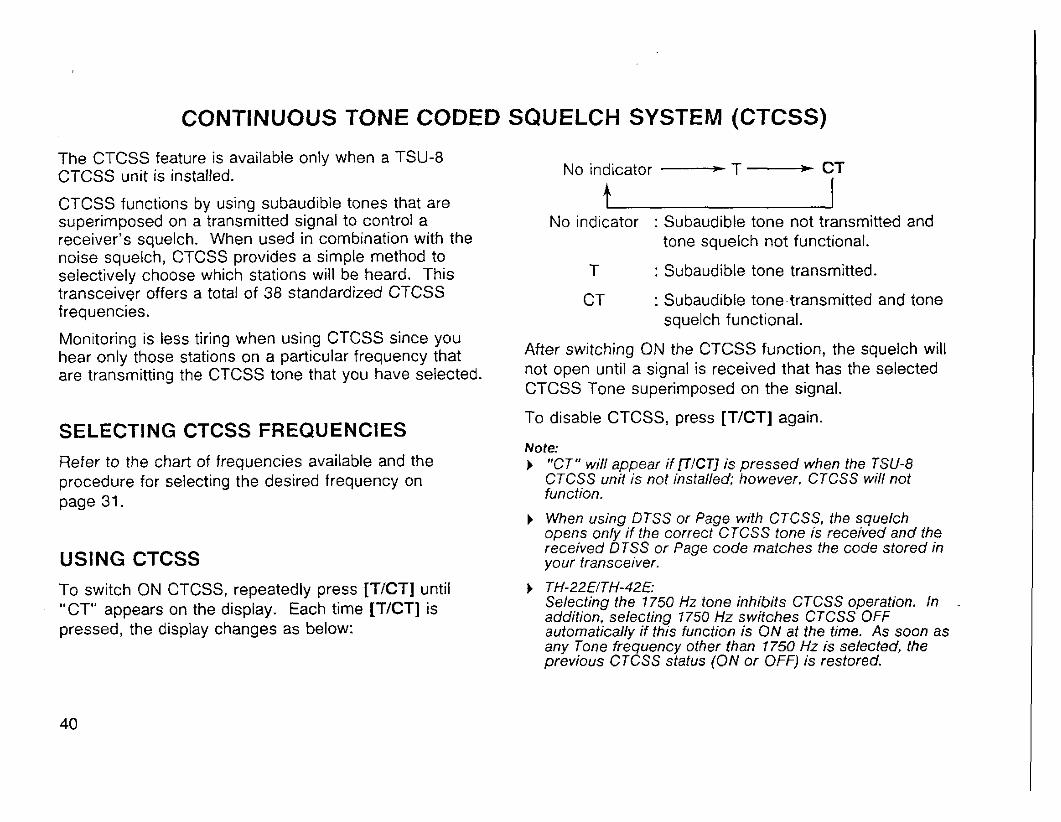
CONTINUOUS TONE CODED SQUELCH SYSTEM (CTCSS)
The CTCSS feature is available only when a TSU-8 CTCSS unit is installed.
CTCSS functions by using subaudible tones that are superimposed on a transmitted signal to control a receiver's squelch. When used in combination with the noise squelch, CTCSS provides a simple method to selectively choose which stations will be heard. This transceiver offers a total of 38 standardized CTCSS frequencies.
Monitoring is less tiring when using CTCSS since you hear only those stations on a particular frequency that are transmitting the CTCSS tone that you have selected.
SELECTING CTCSS FREQUENCIES
No indicator - T - CT
No indicator : Subaudible tone not transmitted and tone squelch not functional.
T : Subaudible tone transmitted.
CT : Subaudible tone-transmitted and tone squelch functional.
After switching ON the CTCSS function, the squelch will not open until a signal is received that has the selected CTCSS Tone superimposed on the signal.
To disable CTCSS, press [TICT] again.
Note: Refer to the chart of frequencies available and the ) "CT" will appear if NCT] is pressed when the TSU-8 procedure for selecting the desired frequency on CTCSS unit is not installed; however, CTCSS will not
page 31. function.
) When using DTSS or Page with CTCSS, the squelch oDens onlv if the correct CTCSS tone is received and the
USING CTCSS received DTSS or Page code matches the code stored in your transceiver.
To switch ON CTCSS, repeatedly press [TICTI until ) TH-22NTH-42E: "CT" appears on the display. Each time [TICT] is Selecting the 7 750 Hz tone inhibits CTCSS operation. In
addition. selectina 7750 Hz switches CTCSS OFF pressed, the display changes as below: automat;callv if thys function is ON at the time. As soon as . . -
any one friquency other than 1750 Hz is selected, the previous CTCSS status (ON or OFF) is restored.
DUAL TONE SQUELCH SYSTEM (DTSS)
DTSS is available only on transceivers equipped with a ACTlVATl N G DTSS DTMF keypad. To switch ON the DTSS function, press IF], [2]. DTSS provides a more refined method than CTCSS to "DT" appears when DTSS is ON. selectively communicate with specific stations. A total of 1000 3-digit DTMF (Dual Tone Multi-Frequency) codes are available to be used as addresses for stations with which you wish to communicate. These codes can be
937 - *- rr - changed easily and regularly as required. Due to the quantity of different codes, large networks can be set up that use DTSS for selective calling and receiving. By Each time this key combination is pressed, DTSS including group codes in the network plan, sub-groups within the network can be contacted without disturbing
toggles ON and OFF.
others monitoring the same frequency. Note:
If your needs are simpler, DTSS also serves a useful ) When [fl, 121 is pressed with Page ON, Page is purpose when you only wish direct communication with a
few close friends on your favorite frequency. A good automatically switched OFF, and DTSS is switched ON.
example of this application is at ham"'entio"s when a ) Both DTSS status and a DTSS code can be stored in a particular frequency can be virtually unusable due to memory channel or the Call channel. Further, when overcrowding. If your group switches ON DTSS, your recalling either a memory channel or the Call channel with squelch only opens when a call with your private address DTSS status ON while using the VFO with Page switched or the group address is received. If no signal is received ON, Page is given priority and the DTSS status switches for more than 2 seconds after DTSS has opened the OFF. squelch, the squelch then closes. Anytime you wish to
) The microphone is inhibited while the DTSS code is monitor all activity on the channel, you simply switch OFF the DTSS function.
transmitted.
) It's advisable to turn OFF Battery Saver when you use DTSS.
PAGE
OVERVIEW PAGE CODE MEMORY Page is available only on transceivers equipped with a The transceiver has 8 Page code memories in total. DTMF keypad. A : Stores your station code. Similar to DTSS, Page uses DTMF codes to address a single station or a group of stations. Page is useful when waiting to receive a call from a specific station. A common group Page code and individual codes should be agreed on in advance. You can select codes from the range 000 to 999 inclusive.
Unlike DTSS, Page offers the added benefit of identifying who called you. The calling station's code appears on the target transceiver's display. If called with an individual code, the individual caller code appears; if called with a group code, the group code appears. This characteristic of Page helps reduce the activity level on a frequency when operators are temporarily absent from their stations. There is no longer a need for repeated calls when your target station is not listening. On return to his or her operating position, their transceiver display will show your station code. They will know immediately that you called.
0 : Stores the calling station's code. The transceiver automatically stores this code while in Receive. You can also use the stored code to respond to the other station.
1 to 6 : Stores group codes or local station codes.
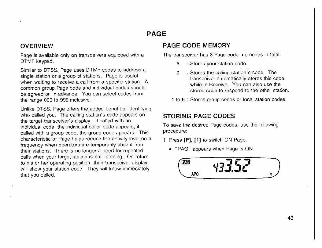
STORING PAGE CODES To save the desired Page codes, use the following procedure:
1 Press [F], [I] to switch ON Page.
r "PAG" appears when Page is ON.
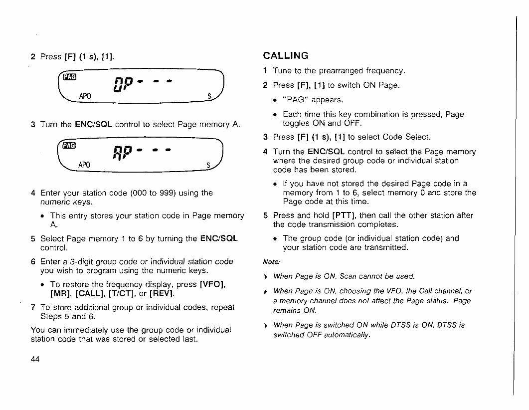
2 Press [F] (1 s), [I]. CALLING
3 Turn the ENCJSQL control to select Page memory A.
4 Enter your station code (000 to 999) using the numeric keys.
This entry stores your station code in Page memory A.
5 Select Page memory 1 to 6 by turning the ENCJSQL control.
6 Enter a 3-digit group code or individual station code you wish to program using the numeric keys.
To restore the frequency display, press [VFO], [MR], [CALL], [TICTI, or [REV].
7 To store additional group or individual codes, repeat Steps 5 and 6.
You can immediately use the group code or individual station code that was stored or selected last.
1 Tune to the prearranged frequency.
2 Press IF], [ I ] to switch ON Page.
"PAG" appears.
Each time this key combination is pressed, Page toggles ON and OFF.
3 Press [F] (1 s), [ I ] to select Code Select.
4 Turn the ENCISQL control to se'lect the Page memory where the desired group code or individual station code has been stored.
If you have not stored the desired Page code in a memory from 1 to 6, select memory 0 and store the Page code at this time.
5 Press and hold [PTT], then call the other station after the code transmission completes.
The group code (or individual station code) and your station code are transmitted.
Note:
b When Page is ON, Scan cannot be used.
I When Page is ON, choosing the VFO, the Call channel, or a memory channel does not affect the Page status. Page remains ON.
b When Page is switched ON while DTSS is ON. DTSS is switched OFF automatically.
RECEIVING 1 Tune to the prearranged frequency.
2 Press [F], [ I ] to switch ON Page.
"PAG" appears.
You are ready to receive a call addressed with your station code or a group code. If no signal is received for more than 2 seconds after a Page has opened the squelch, the squelch then closes.
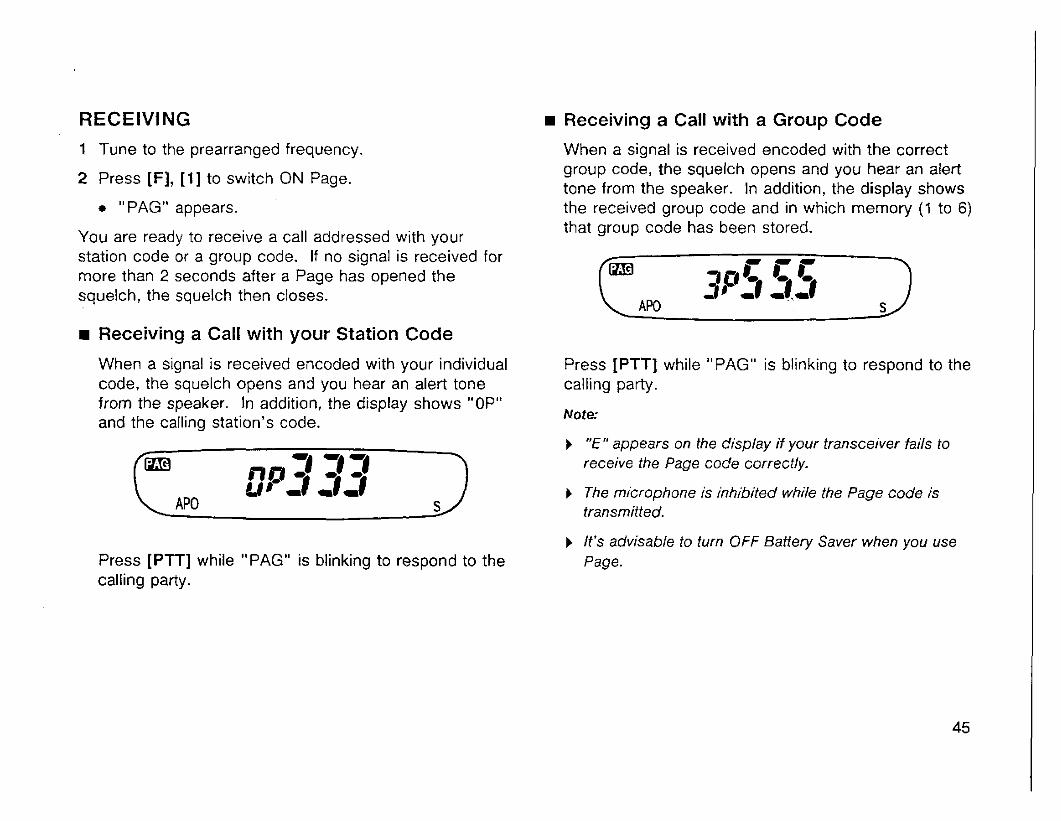
Receiving a Call with your Station Code
When a signal is received encoded with your individual code, the squelch opens and you hear an alert tone from the speaker. In addition, the display shows "OP" and the calling station's code.
Press [PTT] while "PAG" is blinking to respond to the calling party.
Receiving a Call with a Group Code
When a signal is received encoded with the correct group code, the squelch opens and you hear an alert tone from the speaker. In addition, the display shows the received group code and in which memory (1 to 6) that group code has been stored.
Press [PTT] while "PAG" is blinking to respond to the calling party.
Note:
b "E" appears on the display if your transceiver fails to receive the Page code correctly.
b The microphone is inhibited while the Page code is transmitted.
b It's advisable to turn OFF Battery Saver when you use Page.

PAGE CODE AND REPEATERS Pressing [PTT] transmits the Page code after a short delay. This delay helps avoid losing Page data when using repeaters with long response times that may miss receiving a portion of the Page code.
The delay time is 350 ms during simplex operation.
When using transmit offset or split operation, you can change 350 ms (default) to 550 ms.
1 Press [CALL] + POWER ON to enter Menu Set-up.
2 Turn the ENCISQL control to select Menu No. 08.
The current delay time is displayed.
3 Press [CALL] to select "350" or "550".
4 Press any key other than [CALL], [LAMP], or [MONI] to exit Menu Set-up.
LOCKING-OUT CODES The following explains how to inhibit the transceiver from receiving specific Page codes. Although the codes are locked-out from the receiver, the transmitter still transmits a Page on the locked out channels.
1 Press [F], [ I ] .
"PAG" appears.
2 Press [F] (1 s), [ I ] to select Code .. Select.
3 Turn the ENCISQL control to display the Page code to be locked-out.
4 Press [F] (1 s), [LAMP].
A "*" icon on the display indicates the Page code is locked-out.
Each time this key combination is pressed, the selected Page code is locked-out and unlocked alternately.
Note: You cannot lock-out memory 0 that stores the calling station's code.

AUTO PAGE CANCEL OPEN PAGE After successfully paging another station, it is useful to turn OFF Page to eliminate sending a Page code each time you transmit. Auto Page Cancel handles this situation automatically when a station you called responds using the correct Page code to open your transceiver's squelch. On your next transmission, your transceiver then switches OFF your transceiver's Page function.
1 Press [CALL] + POWER ON to enter Menu Set-up.
2 Turn the ENClSQL control to select Menu No. 11.
The current Page Cancel status appears.
The default is "OFF".
3 Press [CALL] to select "OFF" or "ON".
OFF: Does not affect Page status.
ON : Switches OFF Page after transmission.
4 Press any key other than [CALL], [LAMP], or [MONI] to exit Menu Set-up.
When both this function and Page are ON, any signal opens the squelch; however, if a correct Page code is received, the calling station's code appears on the display. This feature is beneficial when you want to generally monitor activity on a frequency but you want to be especially sure not to miss a friend's call.
1 Press [CALL] + POWER ON to enter Menu Set-up.
2 Turn the ENCISQL control to select Menu No. 10.
The current Open Page status appears.
The default is "OFF".
3 Press [CALL] to select "OFF" or "ON".
OFF: Noise squelch functions.
ON : Open Page functions.
4 Press any key other than [CALL], [LAMP], or [MONI] to exit Menu Set-up.
TONE ALERT
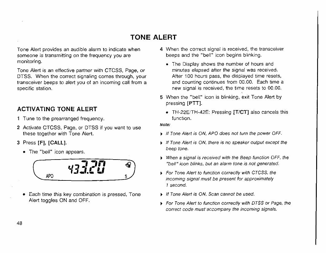
Tone Alert provides an audible alarm to indicate when 4 When the correct signal is received, the transceiver someone is transmitting on the frequency you are beeps and the "bell" icon begins blinking. monitoring. The Display shows the number of hours and Tone Alert is an effective partner with CTCSS, Page, or minutes elapsed after the signal was received. DTSS. When the correct signaling comes through, your After 100 hours pass, the displayed time resets, transceiver beeps to alert you of an incoming call from a and counting continues from 00.00. Each time a specific station. new signal is received, the time resets to 00.00.
ACTIVATING TONE ALERT 1 Tune to the prearranged frequency.
5 When the "bell" icon is blinking, exit Tone Alert by pressing [PTT].
TH-22ElTH-42E: Pressing ITJCT] also cancels this function.
Note: 2 Activate CTCSS, Page, or DTSS if you want to use
these together with Tone Alert. ) I f Tone Alert is ON. APO does not turn the power OFF.
3 Press [F], [CALL].
The "bell" icon appears.
) If Tone Alert is ON, there is no speaker output excepf the beep tone.
) When a signal is received with the Beep function OFF, the "bell" icon blinks, but an alarm tone is not generated.
) For Tone Alert to function correctly with CTCSS, the incoming signal must be present for approximately 1 second.
Each time this key combination is pressed, Tone ) If Tone Alert is ON, Scan cannot be used. Alert toggles ON and OFF.
) For Tone Alert to function correctly with DTSS or Page, the correct code must'accompany the incoming signals.

REMOTE CONTROL
REMOTE CONTROL USING SMC-33 OR SMC-34
Assignable functions are listed below:
1 Function 1 Kev Entry 1) Function I Key Entry I The optional SMC-33 or SMC-34 can be used to remotely control the transceiver for added convenience. The default assignments for the [ l ] , [2], and [3] keys on these options are the functions of the [VFO], [MR], and [CALL] keys respectively on the transceiver (1: VFO, 2: MR, 3: CALL). These keys are referred to as PF keys.
Use the default assignments without further change or, if you prefer, customize the key functions using the following procedure:
1 Make sure that Key Lock is turned OFF on the transceiver.
2 On the option, press [ I ] , [ 2 ] , or [3] + POWER ON.
Example: Press [ 1 ] + POWER ON.
Not= 3 Press the transceiver key(s) for the function that you
wish to assign to the option key pressed in Step 2. ) Turn OFF the transceiver power before connecting the option.
The assignment is completed. Repeat the same ) Locking the transceiver keys with Key Lock does not lock procedure if you wish to assign different functions to the the [ I ] , [2], and 131 keys on the options.
other keys on the option. ) Option keys [ I ] , 121, and 131 are not functional while transmitting.

CONNECTING EQUIPMENT FOR REMOTE CONTROL
Make connections as below when controlling equipment remotely.
Note 1 Note 2 1 OlF
Note 1: Voltage is developed across the 220 Q resistor in the 3 V line. (When 2 mA flows, about 2.5 V is developed.)
Note 2 A 10 pF capacitor is not required in the following cases. Make direct connections.
When the other equipment has DC blocking capacitors.
When a two-terminal condenser microphone is used.
PACKET OPERATION
One of the most exciting benefits of owning a handy FM transceiver nowadays is the ability to use it for VHF or UHF packet radio. Due to the small size of the TH-22/TH-42 series handhelds, they are particularly handy for mobile or portable packet operation. By using a small laptop computer to control any of the widely available Terminal Node Controllers (TNC), and interfacing the TNC to your transceiver via the external
Refer to "CONNECTING OPTIONAL EQUIPMENT" {page 62) for basic connection information for the external microphone and speaker jacks. Consult your TNC instruction manual for additional information about connecting a TNC to your transceiver. Much reference material is available for getting started in digital communications from any store that handles Amateur Radio equipment.
microphone and speaker jacks, you may be surprised at Note: This transceiver is not recommended for 9600 bps how compact and lightweight a digital station can be. Packet operation since using the microphone!speaker jacks Operating packet while on the road from a campsite or as an interface may not provide reliable operation at this high
hotel can be a great way to meet others with common transmission speed.
interests when in a new area or city. Newcomers to digital communications will be surprised to discover what they have been missing.
Similarly, by connecting a home computer or dumb terminal, which you may have in your shack already, to your TNCitransceiver assembly, you can become active on packet with little further monetary investment.
In either case, connecting to one of the many stations with gateways to HF or satellite links can give you national and worldwide messaging capability from your station with nothing more than your handheld for the communications link.

MAINTENANCE
GENERAL INFORMATION SERVICE Your transceiver has been factory aligned and tested to speciiication before shipment. Under normal circumstances, the transceiver will operate in accordance with these operating instructions. All adjustable trimmers, coils and resistors in the transceiver were preset at the factory. They should only be readjusted by a qualified technician who is familiar with this transceiver and has the necessary test equipment. Attempting service or alignment without factory authorization can void the transceiver warranty.
When operated properly, the transceiver will provide years of service and enjoyment without requiring further realignment. The information in this section gives some general service procedures requiring little or no test equipment.
If it is ever necessary to return the equipment to your dealer or service center for repair, pack the transceiver in its original box and packing material. Include a full description of the problems experienced. Include your telephone number along with your name and address in case the service technician needs to call for further explanation while investigating you; problem. Don't return accessory items unless you feel they are directly related to the service problem.
You may return your transceiver for service to the authorized KENWOOD Dealer from whom you purchased it or any authorized KENWOOD service center. A copy of the service report will be returned with the transceiver. Please do not send subassemblies or printed circuit boards. Send the complete transceiver.
Tag all returned items with your name and call sign for identification. Please mention the model and serial number of the transceiver in any communication regarding the problem.
SERVICE NOTE CLEANING
Dear YUOM, The keys, controls and case of the transceiver are likely If you desire to correspond on a technical or operational to become soiled after extended use. Remove the problem, please make vour note short, complete, and to controls from the transceiver and clean them with a the point.' Help us help you by providing the following: neutral detergent and warm water. Use a neutral
detergent (no strong chemicals) and a damp cloth to 1 Model and serial number of equipment
clean the case. 2 Question or problem you are having
3 Other equipment in your station pertaining to the problem
4 Meter readings
5 Other related information
CAUTION: Do not pack the equipment in crushed newspapers for shipment! Extensive damage may result during rough handling or shipping.
Note:
) Record the date of purchase, serial number and dealer from whom the transceiver was purchased.
) For your own information, retain a written record of any maintenance performed on the transceiver.
b When claiming warranty service, please include a photocopy of the bill of sale, or other proof of purchase showing the date of sale.
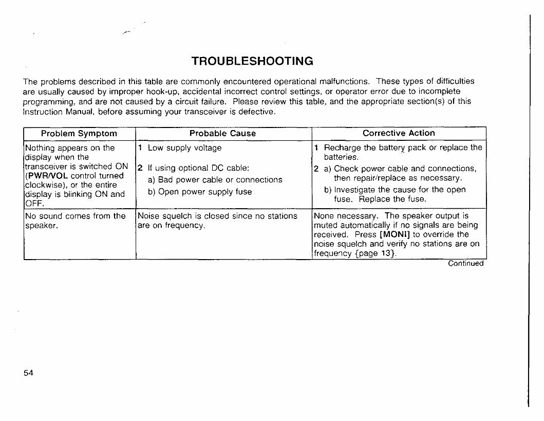
TROUBLESHOOTING
The problems described in this table are commonly encountered operational malfunctions. These types of difficulties are usually caused by improper hook-up, accidental incorrect control settings, or operator error due to incomplete programming, and are not caused by a circuit failure. Please review this table, and the appropriate section(s) of this Instruction Manual, before assuming your transceiver is defective.
Problem Symptom
Nothing appears on the display when the transceiver is switched ON (PWRNOL control turned clockwise), or the entire display is blinking ON and OFF.
No sound comes from the speaker.
Continued
Probable Cause
1 Low supply voltage
2 ~f using optional DC cable: a) Bad power cable or connections b) Open power supply fuse
Noise squelch is closed since no stations are on frequency.
Corrective Action
1 Recharge the battery pack or replace the batteries.
2 a) Check power cable and connections, then repairheplace as necessary.
b) Investigate the cause for the open fuse. Replace the fuse.
None necessary. The speaker output is muted automatically if no signals are being received. Press [MONI] to override the noise squelch and verify no stations are on frequency {page 13).
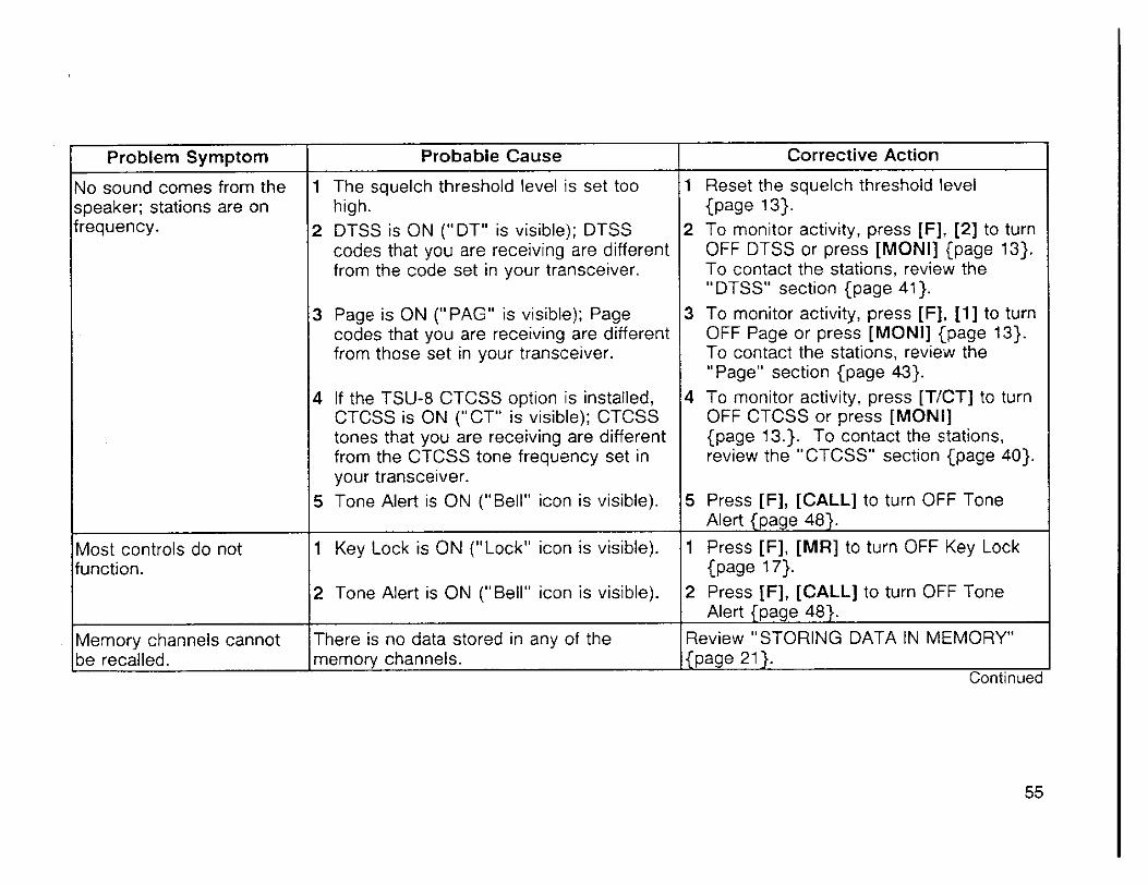
>
Corrective Action
1 Reset the squelch threshold level {page 131.
2 To monitor activity, press [F], [2] to turn OFF DTSS or press [MONI] {page 13). To contact the stations, review the " DTSS" section {page 41).
3 To monitor activity, press [F], [I] to turn OFF Page or press [MONI] {page 13). To contact the stations, review the "Page" section {page 43).
4 To monitor activity, press [TICT] to turn OFF CTCSS or press [MONI] {page 13.). To contact the stations, review the "CTCSS" section {page 40).
5 Press [F], [CALL] to turn OFF Tone Alert {page 48).
1 Press [F], [MU] to turn OFF Key Lock {page 171.
2 Press [F], [CALL] to turn OFF Tone Alert {page 48).
Review "STORING DATA IN MEMORY" {page 21 ). .-. ..
Problem Symptom
No sound comes from the speaker; stations are on frequency.
Most controls do not function.
Memory channels cannot be recalled.
Probabie Cause
1 The squelch threshold level is set too high.
2 DTSS is ON ("DT" is visible); DTSS codes that you are receiving are different from the code set in your transceiver.
3 Page is ON ("PAG" is visible); Page codes that you are receiving are different from those set in your transceiver.
4 If the TSU-8 CTCSS option is installed, CTCSS is ON ("CT" is visible); CTCSS tones that you are receiving are different from the CTCSS tone frequency set in your transceiver.
5 Tone Alert is ON ("Bell" icon is visible).
1 Key Lock is ON ("Lock" icon is visible).
2 Tone Alert is ON ("Bell" icon is visible).
There is no data stored in any of the memory channels.

Problem Svmptom Probable Cause I Corrective Action I Review "INITIALIZING MEMORY" {page 261.
The display shows indicators that are not described in this instruction manual or digits are incomplete. Or, functions do not work as described.
The ENCISQL control will not. select the exact frequency desired.
Memory Scan does not check some or any frequencies stored in your memory channels.
The transceiver will not transmit. A beep is heard each time [PTT] is oressed.
Select a new frequency step as explained in "SELECTING FREQUENCY STEP SIZE" {page 14).
Unlock the channels that you want scanned. Review "Locking-Out Memory Channels" {page 37).
The transceiver needs to be reset.
The current frequency step needs to be changed.
Some or all channels are locked-out as indicated by the " Jr" icon on the display under the channel number when these channels are selected.
A frequency outside the transmit band of the transceiver is selected.
Select a frequency inside the transmit band. Consult "SPECIFICATIONS" {page 63).
The transceiver switches The Automatic Power Off function is ON. Turn the APO function OFF {page 39). OFF for no apparent
Continued

Battery Case BT-9
Wall Charger BC-17
Rapid Chargel KSC-14
DC Cable PG-2W .
Filtered Cigarette Lighter Cable Hand Strap PG-3J HB-2
Swivel Mount BH-6
Water-resistant bag WR-2
Soft Case (for PB-30 & PB-32) Soft Case (for PB-30 & BT-9) Soft Case (for PB-33 & PB-34) Soft Case with Shoulder Belt SC-37 SC-38 SC-39 SC-40
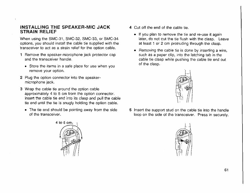
INSTALLING THE SPEAKER-MIC JACK STRAIN RELIEF When using the SMC-31, SMC-32, SMC-33, or SMC-34 options, you should install the cable tie supplied with the transceiver to act as a strain relief for the option cable.
1 Remove the speaker-microphone jack protector cap and the transceiver handle.
Store the items in a safe place for use when you remove your option.
2 Plug the option connector into the speaker- microphone jack.
3 Wrap the cable tie around the option cable approximately 4 to 5 cm from the option connector. Insert the cable tie end into its clasp and pull the cable tie end until the tie is snugly holding the option cable.
The tie end should be pointing away from the side of the transceiver.
4 Cut off the end of the cable tie.
If you plan to remove the tie and re-use it again later, do not cut the tie flush with the clasp. Leave at least 1 or 2 cm protruding through the clasp.
Removing the cable tie is done by inserting a wire, such as a paper clip, into the latching tab in the cable tie clasp while pushing the cable tie end out of the clasp.
5 Insert the support stud on the cable tie into the handle loop on the side of the transceiver. Press in securely.

CONNECTING OPTIONAL EQUIPMENT
W h e n connect ing a n external speaker, an external microphone, or other equipment such as a TNC for packet radio t o the speaker or microphone jack, refer t o the diagram below:
Speaker
Ground
MIC
m I I
Note 1 .-
Note 2 lOuF E
Note 1: Voltage is developed across the 220 resistor in the 3 V line. (When 2 mA flows, about 2.5 V is developed.)
Note 2 A 70 pF capacitor is not required in the following cases. Make direct connections.
When the other equipment has DC blocking capacitors.
CAUTION: To connect an external 24 V power source via a DC-DC converter, only use a PG-3J Cigarette Lighter cable.
r DC-DC converter
Cigarette lighter socket
,-- DC-DC converter . *
Cigarette jighter socket
CAUTION: NEVER use a PG-2W DC cable in this situation; doing so may cause a fire.
PGZW
\- ..:: :: ..: <.x, ..>:.:.
DC-DC converter '.'
When a two-terminal condenser microphone is used.
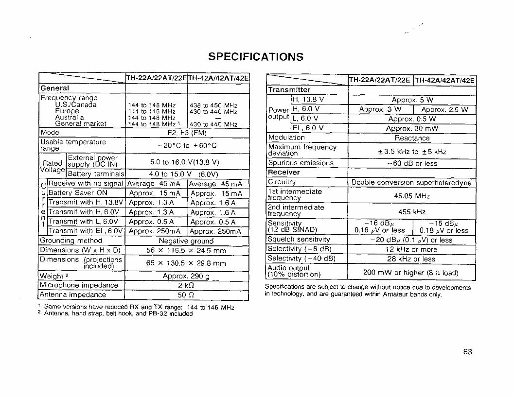
SPECIFICATIONS
144 to 148 MHz
65 X 130.5 X 29.8 mrn
Specifications are subject to change without notice due to developments in technology, and are guaranteed within Amateur bands only.
Some versions have reduced RX and TX range: 144 to 146 MHz Antenna, hand strap, belt hook, and PB-32 included
Transmit ter
power output
TH-22A122ATJ22E I T H - ~ ~ A / ~ ~ A T / ~ ~ E
Approx. 5 W Approx. 3 W I Approx. 2.5 W
Approx. 0.5 W Approx. 30 mW
Reactance -
+_ 3.5 kHz to +_ 5 kHz
-60 dB or less
Double conversion superheterodyne'
45.05 MHz
455 kHz
H, 13.8 V H. 6.0 V L, 6.0 V EL, 6.0 V
-16 dBp 0.16 ,uV or less
Modulation Maxirnurn frequency dev~at~on Spurious emissions Receiver Circuitry I st intermediate frequency 2nd intermediate frequency Sensitivit (12 d~ S ~ A D ) Squelch sensitivity Selectivity ( -6 dB) Selectivity (-40 dB) Audio output (10% distortion)
-15 dBp 0.18 pV or less
-20 dBp (0.1 ,V) or less 12 kHz or more 28 kHz or less
200 m W or higher (8 a load)
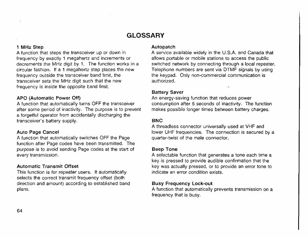
GLOSSARY
1 MHz Step A function that steps the transceiver up or down in frequency by exactly 1 megahertz and increments or decrements the MHz digit by 1. The function works in a circular fashion. If a 1 megahertz step places the new frequency outside the transceiver band limit, the transceiver sets the MHz digit such that the new frequency is inside the opposite band limit.
APO (Automatic Power Off) A function that automatically turns OFF the transceiver after some period of inactivity. The purpose is to prevent a forgetful operator from accidentally discharging the transceiver's battery supply.
Auto Page Cancel A function that automatically switches OFF the Page function after Page codes have been transmitted. The purpose is to avoid sending Page codes at the start of every transmission.
Automatic Transmit Offset This function is for repeater users. It automatically selects the correct transmit frequency offset (both direction and amount) according to established band plans.
Autopatch A service available widely in the U.S.A. and Canada that allows portable or mobile stations to access the public switched network by connecting through a local repeater. Telephone numbers are sent via DTMF signals by using the keypad. Only non-commercial communication is authorized.
Battery Saver An energy-saving function that reduces power consumption after 5 seconds of inactivity. The function makes possible longer times between battery charges.
BNC A threadless connector universally used at VHF and lower UHF frequencies. The connection is secured by a quarter-twist of the male connector.
Beep Tone A selectable function that generates a tone each time a key is pressed to provide audible confirmation that the key was actually pressed, or to provide an error tone to indicate an error condition exists.
Busy Frequency Lock-out A function that automatically prevents transmission on a frequency that is busy.
Call channel A frequency intended for establishing contact with other stations. A transceiver key is dedicated to the Call channel so the frequency can be recalled quickly.
CalllMemory Scan A scan function that allows alternate monitoring of the Call channel and the current memory channel. The current memory channel is the memory channel selected or used last. See "Scan".
CallNFO Scan A scan function that allows alternate monitoring of the Call channel and the current VFO frequency. The current VFO frequency is the frequency selected or used last while in VFO mode. See "Scan".
Channel Display A function that shows only the memory channel number on the display instead of both the frequency and the memory channel number.
CO (Carrier-operated) Scan When scanning, Scan stops at all carriers received and resumes 2 seconds after the carrier stops.
CTCSS (Continuous Tone Coded Squelch System) Also referred to as Tone Squelch. A method of receiver squelch control that uses a subaudible tone superimposed by the transmitter on the transmitted signal. Only signals received with a subaudible tone that matches the tone selected at the receiver can open the receiver squelch.
CTCSS frequency The subaudible frequencies used by CTCSS.
Default settings The values selected for VFO frequency, Call channel frequency, frequency step, etc. by the transceiver after it is reset. All transceivers are shipped from the factory with default settings.
DTMF (Dual Tone Multi-Frequency) signal A signal created by combining two discrete audio frequencies. Generally used for sending digits for repeater control or Autopatch applications.
DTMF Transmit Hold A function that keeps the transmitter keyed while DTMF signals are sent. The function eliminates the need to hold PTT while pressing individual keys to send the DTMF signals.

DTSS (Dual Tone Squelch System) A squelch control system that relies on a burst of data from the transmitter to open the receiver squelch. Only when the transmitted code matches the code programmed in the receiver will the squelch open.
DTSS Transmit Delay The delay intentionally introduced at the transmitter to delay transmission of DTSS codes after PTT is pressed. The delay can improve the reliability of DTSS when communicating with a receiver with slow response time.
Dual function keys Transceiver keys assigned with two functions. This method reduces the number of keys or controls necessary which allows greater reduction in transceiver size.
Encoder (ENCISQL control) The control that alters the transceiver VFO frequency. See "Frequency step".
Encoder Lock A function that disables the ENCISQL control.
Frequency step The size of frequency change produced when the ENCJSQL control is turned one position while in VFO mode.
Group code When using Page, a group will commonly agree on a single code that will be used for calls targeted for all members. This code is the Group code. See "Individual code".
Individual code When using Page, each station must be assigned a unique code that no other station uses. This is the Individual code. Only the squelch of the targeted station will open when a transmission with'this lndividual code is made. See "Group code".
Key Lock A function that disables almost all keys and controls on the transceiver. The purpose is to avoid accidentally changing settings on the transceiver.
Keypad The collection of keys used to send DTMF signals and select DTSS and Page codes.
Locked-out channel An electronically marked memory channel that will be skipped during Memory Scan. This is a quick way to configure your Memory Scan without actually erasing data from memory channels that you may wish to keep.

Memory channel A "storage" location where you record an operating frequency and many other associated parameters for quick recall later. Normally, all commonly used frequencies including those of local repeaters would be saved in memory channels to eliminate manually selecting frequently-used frequencies.
Menu Set-up This is a newer term introduced with the creation of a Menu system for configuring transceiver features. Menu Set-up allows functions to be turned ON or OFF, or values to be set, through software rather than physical keys or controls. Once you learn how to access the Menu, the standardized method of configuring features simplifies operation.
Memory Recall A function that fetches a previously saved operating frequency and associated data. See "Memory channel".
Memory Scan A function that monitors sequentially all programmed memory channels that are not locked-out. See "Scan".
Memory Storage A function that saves an operating frequency and associated data into a memory channel. See "Memory channel".
Memory + VFO Transfer A function that records the current memory channel data into the VFO plus selects VFO mode. This transfer action does not affect the data stored in the memory channel.
MHz Step . . See " 1 MHz S t e ~ " .
Microphone PF (Programmable Function) keys Keys located on some microphones that can have transceiver functions assigned to them. Key assignments can be changed as necessary.
Monitor A function that overrides any squelch systems being used so activity on a frequency can be heard. This is handy to quickly listen to a frequency without actually changing the squelch setting or disabling the squelch system.
NiCd Abbreviation for nickel-cadmium. This refers to the material used to make rechargeable battery packs used in modern transceivers.
Non-standard offset Refers to a transmit frequency offset used to access repeaters that is some value or direction other than that stipulated by existing band plans for a particular region. See "Transmit offset".
Open Page When used in conjunction with Page, all signals received will open the receiver squelch. However, for signals encoded with a Page code, the calling station's Page code appears on the target transceiver's display.
Page A function that allows one station to signal another by sending a transmission encoded with a Page code that only opens the squelch of a receiver with the same code selected. The calling station's code identifier appears on the target station's display after a successful Page.
Page code memory A memory channel dedicated to storing only Page codes. See "Page".
Page Transmit Delay The delay intentionally introduced at the transmitter to delay transmission of Page codes after PTT is pressed. The delay can improve the reliability of Page when communicating with a receiver with slow response time.
PTT (Push-to-talk) Refers to the non-latching switch that changes the transceiver from Receive to Transmit mode.
QSO Refers to a contact between two Amateur stations.
Repeater A station, usually installed in a central location at a high elevation, designed to receive and-re-transmit signals. The purpose of a repeater is to increase the receive and transmit range of stations able to access the repeater.
Reset (initialization) The act of restarting the transceiver microcomputer. Depending on the type of reset done, some or all memory may be erased and set to default values. A reset can be done as a last resort when the transceiver appears to be malfunctioning.
Reverse A function that switches the transmit and receive frequencies.
Scan The general term for several functions that allow a series of frequencies or memories to be monitored sequentially and automatically without intervention by the operator.

Simplex channel Refers to a communications channel where the receive and transmit frequencies are the same.
Split channel Refers to a communications channel where the receive and transmit frequencies are not the same.
Squelch A function that automatically mutes a receiver's speaker output when no receive signal is present. Functions most reliably when communicating via full carrier modes such as FM.
SWR (standing wave ratio) An antenna that is not correctly matched in impedance with a transmission line and transmitter will reflect some portion of the transmitted signal back toward the transmitter. This causes a standing wave pattern to develop. The ratio of maximum to minimum voltage (VSWR) on the transmission line when such a condition exists is commonly referred to as the SWR.
TO (Time-operated) Scan ,,,
When scanning, scan stops at all carriers received and resumes after 5 seconds.
Squelch threshold level The receive level at which a receiver's speaker output is muted. This level is usually adjustable, either manually or automatically by the transceiver microcomputer.
Tone Alert A function that alerts an operator via a visual and audible alarm when the receiver squelch opens.
Tone frequency See " Subaudible tone".
Standard offset . Refers to a transmit frequency offset used to access repeaters that is equal to the amount and direction stipulated by existing band plans for a particular region. See "Transmit offset".
Subaudible tone A low-frequency non-audible signal superimposed on a transmitted signal for the purpose of accessing some types of repeaters.
TOT (Time-out Timer) A function that automatically forces a transceiver from Transmit back to Receive after timer expiration.
Transmit Inhibit A function that stops a transceiver from transmitting. The function has no effect on the receiver or receive functions.

Transmit offset (shift) All Amateur voice repeaters operate on separate transmit and receive frequencies. Transmit offset refers to the amount that a transmit frequency is different from a receive frequency. See "Transmit offset direction".
Transmit offset (shift) direction Refers to the direction, either plus ( + ) or minus (-), that a transmit frequency is with respect to a receive frequency. Both the direction and amount of offset must be selected correctly to access a repeater. See "Transmit offset".
Tuning Encoder Lock See "Encoder Lock".
VFO (variable frequency oscillator) mode The mode that allows any individual frequency to be selected within the range of the VFO only restricted by frequency step limitations. When in VFO mode, frequencies are selected using the ENCISQL control.
VFO Scan A function that monitors sequentially all frequencies that can be selected using the ENCiSQL control while in VFO mode. See "Scan".
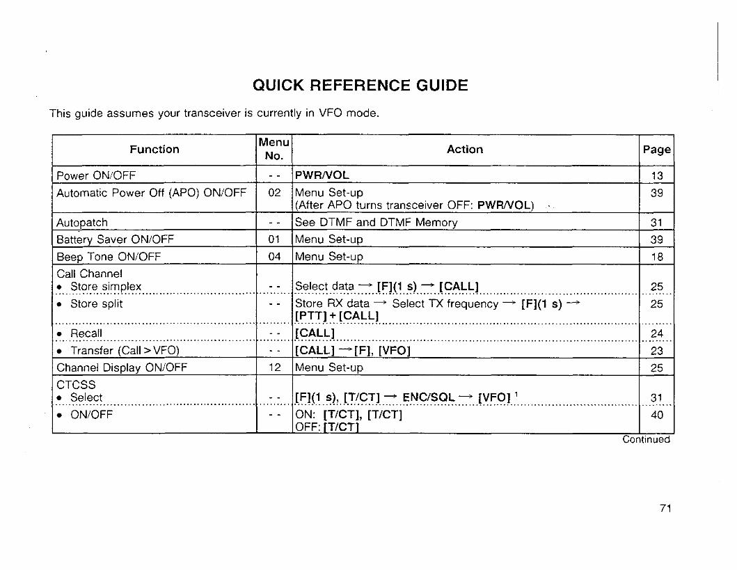
QUICK REFERENCE GUIDE
This guide assumes your transceiver is currently in VFO mode.
Function
Power ONIOFF
Automatic Power Off (APO) ONIOFF
Autopatch
8attery Saver ONIOFF
Beep Tone ONIOFF
Call Channel Store simplex
Store split
Recall
Transfer (Call > VFO)
Channel Display ONIOFF
CTCSS Select
ONIOFF
Menu No. - - 02
- - 01
04
- - - -
- - - - 12
- - - -
Action
PWRNOL
Menu Set-up (After APO turns transceiver OFF: PWFUVOL) . See DTMF and DTMF Memory
Menu Set-up
Menu Set-up
Select data -- [F](l s) - [CALL] ................................................................................................................................................................................ Store RX data - Select TX frequency - [F](1 s) -+
[PTT] + [CALL] ............................................................................................................................................................................... [CALL] ................................................................................................................................................................................ [CALL] +[F], [VFO] Menu Set-up
[F](1 s), [TICT] + ENCISQL - [VFO] ' ............................................................................................................................................................................... ON: [TtCT], [TICTI OFF: [TICTI
Page
13
3 9
31
39
18
25
25
24
23 25
31
40
Continued
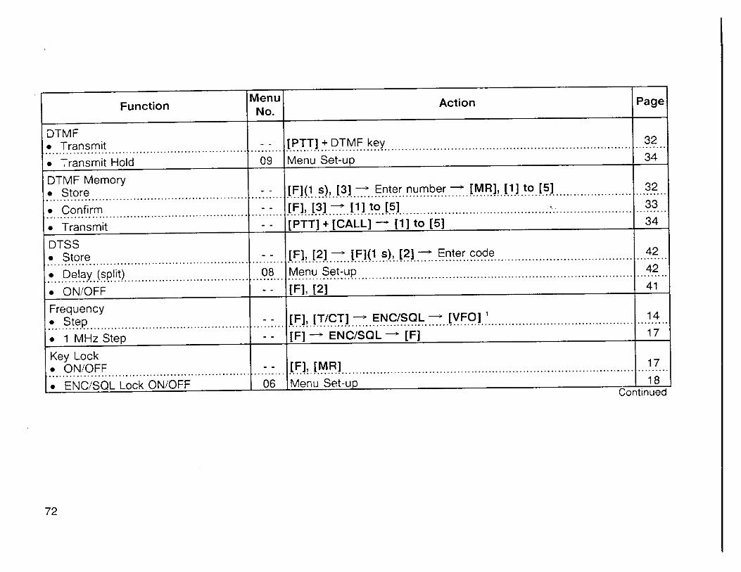
Page Function
DTMF Transmit
Transmit Hold
DTMF Memory Store ................... .................................................. Confirm
Transmit
Menu No.
- -
09
DTSS Store . Delay (split)
ONIOFF
ENCISQL Lock ONiOFF Continued
Action
- -
- -
- -
Frequency Step
1 MHz Step
[PTT] + DTMF key ................................................................................................................................................................................. Menu Set-up
- - .........
08 - -
32
34
[F](I s), [3] + Enter number - [MR], [ I ] to [5] ............................................................................................................
[Fl, [31 - 111 to 151 ............................................................................................................................................................................... [PTT] + [CALL] ' [ I ] to [5]
- - - -
32
33
34
[F], [2] -+ [F](l s), (21 -+ Enter code
................................................................................................................................................................................ Menu Set-up [Fl, (21
......... 42 42 1 4 1
[F], [TICT] -+ ENCfSQL -' [VFO] ' ................................................................................................................................................................................ [F] -+ ENCISQL + [F]
14
17
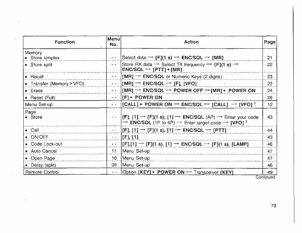
Memory Store simplex ........................................................ Store split
Function
Recall ........................................................
Menu No.
[MR] + ENCISQL or Nurner~c Keys (2 d~g~ts ) ................. ............................... I ............................................. : :..:
Select data -+ [F](l s) - ENCISQL + [MR] ........................................................................................................... Store RX data + Select TX frequency + [F](l s) -+
ENCISQL IPTTl+ IMRl
Erase
Action
21
22
Reset [Full) I - - I I F ~ + POWERON
Page
Page Store
Menu Set-up - - CALL] + POWER ON + ENCISQL -+ [CALL] --' [VFO]
................................................................... Call ................................................................... ONIOFF .................................................................... Code Lock-out ................................................................... Auto Cancel .................................................................... Open Page ................................................................... Delay (split)
Remote Control
12
[F], [ I ] - [F](1 s), [ I ] - ENCISQL (AP) - Enter your code + ENCISQL (1P to 6P) - Enter target code + [VFO] ...........................................................................................................
- -
- -
- - 11
10
08 - -
Menu Set-uo 1 46
43
[F],[ l ] + [F](l s), [ I ] - ENCISQL - [F](l s), [LAMP] ........................................................................................................... Menu Set-up ........................................................................................................... Menu Set-up ...........................................................................................................
opt ion [KEY] + POWER ON -- Transceiver [KEY] 1 49 Continued
46
47
47

Function
Repeaters TX Offset direction Auto TX Offset Cancel
TX Offset amount Reverse ON/OFF Tone ONIOFFT
Tone select Reset
VFO (Partial) Memory (Full)
Scan Scan Resume Scan PauseiContinue
Memory Scan
Memory Lock-out ONIOFF VFO Scan
CallNFO Scan
CalllMemory Scan
Menu No.
- - 07 - - - - - -
- -
- - - -
03 - -
- -
- - - -
- -
- -
Action
[Fl, [REV] ................................................................................................................................................................................ Menu Set-up ............................................................................................................................................................................... [F](1 s), [REV] -+ ENCISQL --+ [VFO] ' ................................................................................................................................................................................ [REV] ............................................................................................................................................................................... ON: [TICT] .-
OFF: [TICT], [TICT] ................................................................................................................................................................................ [F](1 s), [TICT] -+ ENCfSQL -+ [VFO] '
[VFO] + POWER ON ............................................................................................................................................................................... [F] + POWER ON
Menu Set-up ............................................................................................................................................................................... Pause: Hold [MONI] Continue: Release [MONI] ................................................................................................................................................................................ Start: [MR](l s) ' ENCISQL Stop: [VFO] ' ................................................................................................................................................................................ [MR] - ENCfSQL - [F](1 s), [LAMP] ............................................................................................................................................................................... Start: [VFO](l s) ' ENClSQL Stop: [VFO] ' ................................................................................................................................................................................ Start: [VFO] +- [CALL](l s) Stop: [VFO] ' ............................................................................................................................................................................... Start: [MR] * [CALL](l s) Stop: [VFO] '
Page
27 29
29 30 30
31
26 26
36
36
37
37 38
38
38

Function Menu I M n I Action
Squelch threshold
Tone Alert ONiOFF
- Transmitting
Busy Frequency Lock-out ONiOFF
Power output
Time-out Timer (TOT) ............................................................... TX Inhibit ONiOFF
' Any key other than [LAMP] or [MONI] Any key other than [LAMP], [MONI], or [CALL] [VFO], [MR], [CALL], pICT], or [REV]
. --. - - - -
VFO Select
Reset (Partial)
14 - - 13
05
[F], [MONI] it ENCISQL -+ [VFO] ' ON: IF], [CALL] OFF (before call): [F], [CALL] OFF (after call): [PTT] TH-22ERH-42E: Also [TICT]
- - - -
13
48
..................................................................................................................... Menu Set-up ..
IF], [PTTl ................................................................................................................................................................................ Menu Set-up
Menu Set-up
20
19
19 .I.......
20
[VFO] ............................................................................................................................................................................... [VFO] + POWER ON
14
26